


Installation and Use Instructions
TL-2015R2
Wireless Central Monitor and
Nurse Call Paging System
Optional Accessories
Pager
433-PGD
Caegiver Pocket Pager with
LCD Display
Pager
433-NC
Wireless Nurse Call Button
SMART CAREGIVER CORPORATION
Tel: (800) 650-3637 www.smartcaregivercorp.com
1

Connection Diagrams for Large Facility Central
Monitor (TL-2015R2)
Large Facility Central Monitor (TL-2015R2)
2

CONTENTS
1.0 INTRODUCTION
2.0 SETTING UP AND INSTALLING THE CARE STATION
3.0 OPTIONAL INTERFACE/EXPANSION UNIT
4.0 APPROVALS
5.0 SUMMARY OF FEATURES AND FUNCTIONS
6.0 TECHNICAL SPECIFICATIONS
7.0 USER INSTRUCTIONS
8.0 LIST OF COMPATIBLE AND ASSOCIATED EQUIPMENT
3

1.0 INTRODUCTION
The multi-purpose, TL-2015R2 central monitor can operate in small stand-alone call bell systems, or can be
the heart of an extensive Smart wireless or cabled alert system. Ease of installation, simplicity of operation and
economy are the main system features.
Systems having multiple TL-2015R2 with external field receivers can cover other areas/floors of buildings and up
to ten (10) TL-2015R2 central monitors can be employed in one area, or site.
The TL-2015R2 central monitor combines with our TL-3004SYSR1, TL-3005SYSR1 door monitoring and Bed/
Chair CordLess® monitoring systems, wristband wireless transmitters, nurse call buttons and other Smart
wireless products, to provide indication and display of alert calls. It is a “supervised” system, automatically
detecting equipment faults on various products, which are identified and displayed on the front panel LCD.
An interface unit is available for expansion of this central monitor to cover larger installations and standard, preprepared interconnection cables are supplied that simply plug in to complete the system. This interface/junction
(CMJ-01) unit can integrate one internal and up to five (5) external field data receivers (CMRX-01).
This latest version can respond to “emergency” calls from field equipment by providing different sound and
display indications.
In addition, a stand-alone wireless transponder (repeater unit: WBUM-02) is available that can substantially
increase the distance at which the TL-2015R2 can operate with our other wireless transmitter products. The
repeater does not apply to the cordless pads but these devices do have extended range of up to 200M. All other
devices will work with the repeater.
2.0 SETTING UP AND INSTALLING THE TL-2015R2
Please refer to drawings 1, 2 and 3. First adjust the controls to the required settings. Various controls will be
found in the rear panel of the unit.
With the OORC switch “off” (in the rear of the unit) the central monitor “memory” will be cleared of any previously
stored fault detection codes. Please refer to section 2.1.2 (a) Out of Range Check and 7.3.2 Field unit fault
detected (b), below.
2.1 User selectable controls
2.1.1 Reset functions
A two-way switch is provided at the rear of the unit on the left hand side as you view the back for selection of
user preferred Reset function.
If the “MAG RST” option is selected, the user needs to present the Caregiver Key (CK-01) as proximity reset
device at the point on the unit front panel (marked with a circle and labeled “Key”). If the “BUT RST” option is
selected, the user simply presses the Reset button (Acknowledge Button) mounted on the front panel of the unit.
When the “MAG RST” option is selected, the front panel Reset button is disabled.
4

2.1.2 Automatic out of range and interference check function
(A) OUT OF RANGE CHECK (OORC) AND AUTOMATIC ALERTS
A switch is provided at the rear of the unit to enable, or disable this function dependent upon user preference.
This is second from the left as you view the back of the TL-2015R2.
Provided that this “auto-checking” function is switched on, up to 200 field units (wireless transmitters) such
as door monitors, bedside monitors etc. can be automatically “logged” into the central monitor memory by
transmitting a signal from each unit.
Thereafter, the field equipment automatically transmits a checking signal to be received by the TL-2015R2 at 6
hourly intervals and should this fault checking signal be missed for 4 consecutive transmissions (24 hours) the
central monitor will give an alert and display to report the particular field unit missing. (Note: This may have to
be switched on for the particular unit In the programming routine e.g. wireless bed monitors or nurse call
buttons etc)
Other field unit faults will be reported as an alert i.e. “Low Battery”, “AC Loss” etc.
(b) Interference check
The TL-2015R2 has an interference detect circuit. When a continuous interfering signal is on the same wireless
channel, this will be indicated on the central monitor display. You must find the source of this interference or the
system may not work properly. The hand-held tester unit may help locate the source in this case.
c) Testing the wireless transmission on the site
Up to 80 metre (250ft) wireless range between devices is normal for Smart fixed devices in open space. A 50
metre (160ft) distance is recommended as maximum to the nearest receiver to ensure a reliable transmission.
Any barriers such as walls will reduce this range and therefore you must test on the each site with the
transmitters installed in their correct positions, performing several test calls. (Examples: bed monitor, door
monitor, toilet buttons, and so on)
In the case of alert Tx wristbands, perform the tests throughout the building where cover is required, for example
corners of rooms, toilets, kitchens and so on.
(Note: This may include the wristband remove feature if this is used or Caregiver Key reset function, if this is
used – caregiver uses a Caregiver Key to reset on reaching the patient.)
2.1.3 Volume Adjustment
The user may adjust the potentiometer provided in the rear of the unit for adjustment of the required alert level
(Volume). This control is turned counter-clockwise to increase the volume of sound.
2.1.4 TL-2015R2 Area/ID selection (0-7 allowed)
A rotary switch is provided in the rear of the unit, fourth from left. Position “0” sets the unit to universally decode
and indicate calls from any compatible field equipment. If a particular door monitor unit, bed monitor, or other
Smart device is required to work with a particular TL-2015R2, the Area/ID in the door monitor/bed monitor must
5

be set to match with the rotary ID switch in the Tl-20115R2 unit.
Please note that switch positions 8 and 9 are not used and should not be set.The Area ID selection is especially
useful where different wards or floors within a building are operated independently, for example, floor 1 would set
to area code 1, floor 2 set to area code 2 and so on.
2.1.5 PC and Printer Connection
The COM port socket in the rear of the TL-2015R2 can be used for connection of the system e.g. to a PC, or
printer for recording events. A database on the PC may be optionally used to display a mimic of the premises
plan showing alert positions as events occur and to analyze events history for management purposes. (Refer to
drawing 8.)
Requirements:
PC: with serial port support,
Printer: Dot matrix (eg. EPSON, LQ-300+II), with serial port support.
Serial port setup: baudrate 9600 bps, 8-bit data, 1-Stop bit and no parity bit.
And the output looks like this:
Toilet Alert ID: 010123 2011-01-26 16:27:06
2.1.6 Data In/Out
This is a spare port for future development.
2.1.7 Relay O/P
May be used for Normally Open or Normally Closed purposes depending on plug wiring. Consult with your facility
manager for more information.
2.2 Power
The unit can use a dedicated 12VDC power supply (rated at 250mA, or above). In the event of AC main power
failure, or low battery condition an alert message will be indicated on the LCD display accompanied by a “beep”
sound. Battery “back-up” power is provided in the event of AC mains supply failure by fitting a block of NI-MH 6V
rechargeable batteries (e.g. NOVACELL) in battery box on the bottom of the monitor.
Important. : When shipped these batteries are not plugged in. These must be plugged in and charged when
installed. Do not let these batteries go flat for a prolonged period of time.
2.3 Interface 1 and Interface 2
These sockets are for connecting the Optional Interface / Expansion Units for field receivers to expand range –
see section 3 below.
6

2.4 Alert and Emergency Call indications
The TL-2015R2 will respond to an “alert” call received from a field unit by displaying the information on the LCD
and emitting a “pulsing” tone and lighting the Alert LED.
It will respond to an “emergency” call received from a field unit by displaying the information and emitting a
“steady” (continuous) tone.
3.0 OPTIONAL INTERFACE/EXPANSION UNIT (SEE DRAWING 1)
For small installations, the unit has an internal wireless receiver and it will pick up various transmitter signals
directly and send to the desktop unit.
Where a larger area is to be covered using various Smart wireless products, up to 5 external receivers can be
added to increase the area of coverage and the operational range of the system connected via the expansion unit
(CMJ-01), which is plugged into Interface 1 and Interface 2 sockets at the rear of the TL-2015R2. The receivers
(CMRX-01) are supplied complete with an 8-metre cable as standard. This can easily be extended using standard
telephone style extension cables commonly available from most DIY stores. The length of such cable extension
can be up to 250 metres. Each field receiver can detect data signals from an area having a radius up to 50
metres (150ft), subject to survey and system range testing. Note that the TL-2015R2 will provide an alert if a field
unit is out of range (see item 2.1.2 above).
3.1 Out of range feature (note: This applies to all transmitters except CordLess®
bed pad transmitters. See section 7.4 for CordLess® pad operation)
• Enable this feature by setting the OORC function switch (at the rear of the
unit) to “on."
• Press the alert button of the field unit to be included in the system.
• The field unit ID will initially appear on the TL-2015R2 LCD as an alert signal
and confirms that setup range is OK.
• Reset the calling field unit.
• Following a short delay, the TL-2015R2 will display the unit ID as “added”.
If the TL-2015R2 does not receive its periodic (6 hourly) signal from that particular unit for a total period of 24
hours, the missing field unit ID will be displayed as a fault. (You must make sure the periodic checking signal is
switched on, on the field transmitter unit)
To turn “off” this out of range/equipment fault feature, set the OORC switch to “off”. This automatically removes
any stored field equipment checking codes from the TL-2015R2 memory.
7

3.2 Interface unit and interconnections
3.2.1 Power
A socket is provided at the rear of the TL-2015R2, also on the Interface unit for connection of a 12VDC power
supply, or AC main adaptor. If the Interface unit is to be used, only one power supply unit is required as power
is routed to the TL-2015R2 via the standard interconnection cable (see drawing 5). Please refer to your supplier
before connecting other non standard external devices such as indicator lights as a larger power supply may
be required.
3.2.2 Interface and Central Monitor Alert outputs
Steady volt free alert outputs are provided via the 6.3mm jack socket at the rear.
Alert outputs are also available via the ¼” jack socket in the side of the CMJ-01 interface unit that provides
the choice of “steady”, or “pulsing” outputs, according to user requirements. These outputs are for operation of
external indicators, or other “slave” equipment. Please refer to your supplier before connecting external devices
that may draw higher current from the unit. It is possible that a larger power supply will be required in these
circumstances. Note that the maximum current rating from these alert volt free contact outputs is 1 amp.
3.2.3 Interface interconnection cables
If the interface unit (CMJ-01) is to be employed and only it’s incorporated field data receiver is to be utilised, a
standard pre-prepared cable connects between the “Interface 1” socket on the Interface unit and the “Interface
1” socket on the TL-2015R2 (see drawing 1).
One field receiver is fitted inside the interface unit. If additional field receivers are to be included (up to a total of
5 external receivers, (CMRX-01), a further pre-prepared cable connects between the “Interface 2” socket on the
Interface unit and the “Interface 2” socket in the rear of the TL-2015R2.
Additional receivers can be connected to the interface unit at sockets “External Receivers 1 – 5” (see drawings
1 and 5).
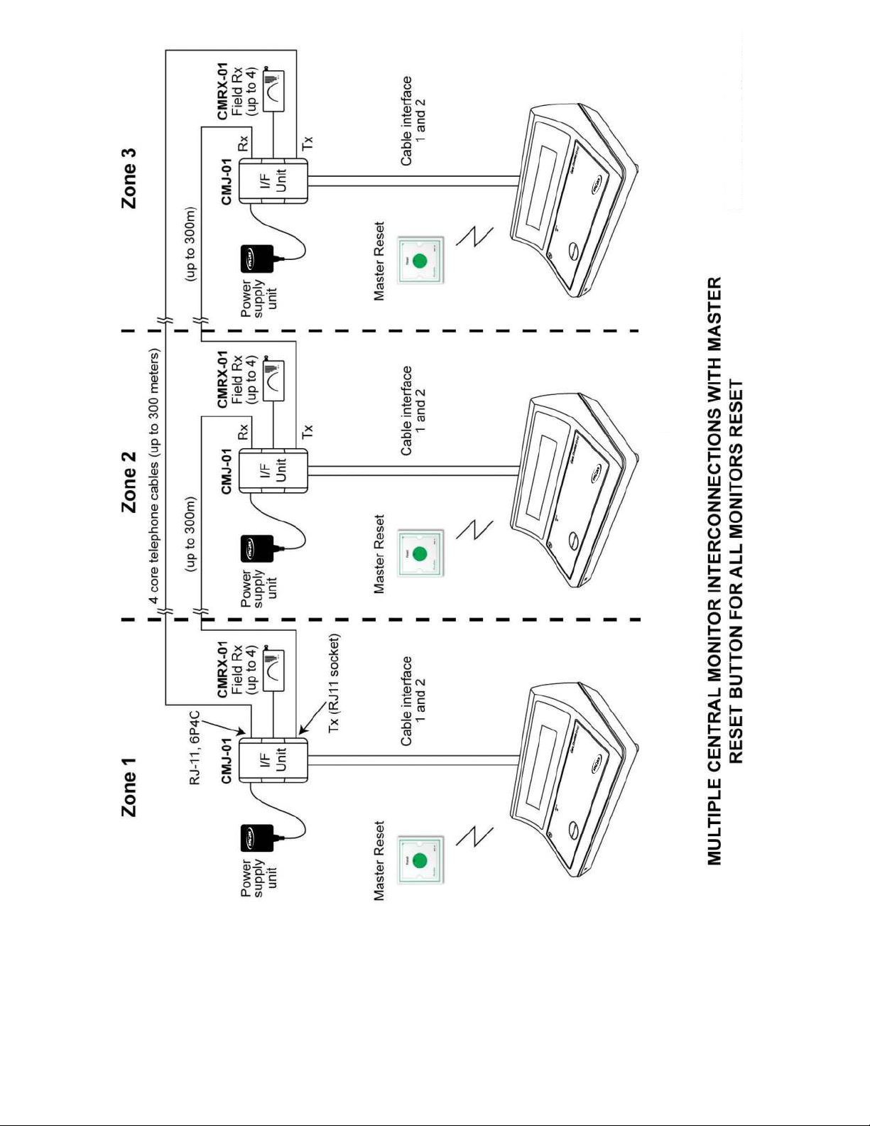
3.2.4 Connection to other TL-2015R2
The “Tx” socket in the Interface unit can transmit wired data via a bus to another TL-2015R2 through a vacant
“External Receiver” port in its (CMJ-01) interface unit (please refer to drawing 1 and 7). These can be connected
using standard four (4) core telephone cable commonly available at most DIY stores.
The TX output socket to other CM units needs a RJ-11 type telephone plug (4P4C) and the input sockets for the
receivers use a RJ-11 type telephone plug (6P4C). All cables are standard 4 core telephone cable compatible
with the above plugs. (Note: Max length tested of the connecting cable is 300 metres (1000ft) for each individual
length. Refer to drawing 7)
8

3.2.5 Alert indicator light
The CMJ-01 interface unit features a “Visual Alert” light on the front panel (see drawing 3).
3.2.6 Master Reset
For single TL-2015R2, to reset its alert, simply pressing on the “Acknowledge” button or using Caregiver key
(CK-01) (Refer to section 2.1.1), or using a wireless reset button which is programmed to “Master
Reset” function.
For multiple TL-2015R2 connected together, in order to reset all TL-2015R2, one should use “Master Reset”
button to reset all of them at the same time, otherwise reset each by pressing the “Acknowledge” button or using
Caregiver key (Refer to section 2.1.1).
On drawing 9, each TL-2015R2 is located at different zone with a master reset button nearby. Pressing on the
master reset button will reset the same zone’s TL-2015R2, and then the TL-2015R2 transfers it to the
next TL-2015R2.
3.2.7 Frequencies of Transmission and Reception
For TL-2015R2, the frequencies of transmission (TX) and reception (RX) should be different, or its transmission
may be interference by other transmitters. This is also applied to the extension’s receivers through CMJ-01.
(Please refer to the bottom of TL-2015R2 for the frequency configuration of the device.)
4.0 APPROVALS
For information, Smart digital wireless transmitters and receivers are FCC certified and comply with
Telecommunication (Low Power Devices) standards throughout the world. Our products are also CE registered
and ETL (UL equivalent). This product is manufactured to ISO9001 (year 2000) Standard.
5.0 SUMMARY OF FEATURES AND FUNCTIONS:
5.1 The TL-2015R2 unit has a large, 2-line LCD display
5.2 Selectable automatic out of range (OORC) and interference check with indication.
5.3 Automatic AC main power supply failure detection with indication
5.4 Indicates and can send on automatic fault alerts from other Smart equipment
5.5 Standard pre-prepared (plug-in) interconnection cables
5.6 Compatible with other Smart systems and monitoring equipment
5.7 Data outputs for system integration e.g. PC, printer, etc
5.8 Selectable Caregiver key , or manual button Reset function for local operation
5.9 Programming port
5.10 Adjustable volume
9

5.11 TL-2015R2 Area/ID selection (8 codes)
5.12 Data bus output for connecting multiple TL-2015R2 units
5.13 Alert outputs for external indicators, or other “slave” equipment
5.14 Output for large external display
5.15 12VDC AC mains adaptor/power supply connection
5.16 Internal rechargeable battery back up with “low battery” detection
6.0 TECHNICAL SPECIFICATIONS
1) Operating Frequency: 315MHz (FCC approved), or 433.92MHz (CE)
2) Operating Power
(a) AC mains adaptor (for regional ac voltage input): Regulated 12VDC output (UL/CE approved), or
Batteries: 6V (block of NI-MH batteries)
(b) Current rating for TL-2015R2 (no door lock, or flash light) = 250mA
3) Battery life: In “standby” (ac mains fail) mode, assured 10 hours - dependent upon alert activity
4) Relay contact output: Normally open volt-free contact.
5) Maximum rating for relay output contacts: 1 amp (e.g. for door lock)
6) Display: Simultaneous alphanumeric text for several detected patient transmitter units. These alerts
“rotate” in the display window.
7) User selectable “Reset” function
8) Adjustable volume (potentiometer)
9) Low battery and ac power loss detection with alert
10) Automatic “Out Of Range” and “Interference” detection with alert.
11) Dimensions of housing: 242mm x 168mm x 116mm.
7.0 USER INSTRUCTIONS
The Large Facility Central Monitor is designed to be easy to fit and simple to use, requiring the press of a single
button in its simplest user operation. The three operator functions are: adding new units, resetting alerts and
clearing fault indications.
7.1 Adding field units into the central monitoring system
Each TL-2015R2 unit has a memory capacity for up to 200 field units for a supervised system. When an alert is
activated in your area, the field unit is automatically added into the TL-2015R2 memory. No action is required by
the user.
10

7.2 Acceptance and reset of an alert
When the TL-2015R2 receives an alert signal, it is automatically displayed in the LCD showing type of alert with
field unit identity number. A pulsing sounder alerts the user that there is an alert.
To reset an active alert at the TL-2015R2, press the manual reset button on the front panel and then attend to the
patient calling.
When the reset button is pressed the system will rotate any alerts on the display for approximately 10 seconds
before the display is cleared as a reminder of alerts on the system.
A bed monitor return signal will remain on the display to remind you that a patient is moving and will issue
two beeps.
Some alert units such as a bed head alert, door monitor and bed monitor, will remain in an alert state until reset
at the source so resetting at the TL-2015R2 central monitor will only be temporary and you must reset at the unit
to clear the alert.
In the case where it is desired to have greater security on the TL-2015R2, the reset button may be disabled
during installation. In this case only the Caregiver key can be used by the caregiver to reset the alert, and the
reset button is disabled.
7.3 The central monitor OORC system auto checking function (if enabled)
Used to detect if a field unit becomes faulty, or wireless interference is sensed. This is reported and indicated at
the TL-2015R2.
7.3.1 Wireless interference detected
The TL-2015R2 will display “Interference Detected” and emit a “beep-beep” sound. This will continue until the
interference is removed.
7.3.2 Field unit fault detected
Field units automatically send a “report” signal to the TL-2015R2 approximately every 6 hours.
With the OORC switch on, if a field unit does not report by transmitting 4 consecutive signals (in a period of 24
hours) the central monitor will display (for example) “Bed Head Fault” together with the particular field unit 4
digit identity number. This will be displayed until the TL-2015R is reset (see 2.1.1 above).
If this field unit continues to be faulty, or “out of range” (no report signal), the central monitor will again display
and indicate a fault after a further 6 hours.
In the case of a field unit being removed from the system, it needs to be removed from the TL-2015R2 memory.
This is simply done by turning “off” the OORC switch, and then switching back “on” (if continued auto fault
checking required).
With the OORC switch turned “on”, any new field unit/identity being added to the system will automatically be
added to the central monitor fault checking memory with its first alert transmission.
11

Turning “off” this OORC switch will automatically clear the fault checking memory of the central monitor and it
will cease to respond to any periodic fault checking signals from field equipment.
(note: You should check that each unit on the system is working correctly after the OORC has been turned off
and you should do a routine check of the system).
The next section is the new section added to allow the new CordLess® pad function to work
with The TL-2015R.
7.4 CordLess® PAD operation
The cordless PAD function is implemented in “menu” style. It uses Caregiver key and “Acknowledge” button
(A-Key) to operate this function.
7.4.1 Register the CordLess® PAD
To use a cordless PAD, you must first is to register its ID in to TL-2015R2. So it needs the following functions to
operate the registration.
Wireless
TL-2015R2
- Enter into setup mode (You must use the caregiver key for this)
Press the A-Key and also put C-Key on the “Key” position at the same time, wait about 6 seconds, TL-2015R2 will
beep 2 sounds and then release both C-Key and A-Key, it will enter into the setup mode.
SETUP V1.6
:> Cordless Pad
There are two options in the setup menu, “Cordless PAD” or “Clock Time”, the first item is the “Cordless PAD”.
On this menu, press A-Key to show next item, and C-Key to confirm the selection.
Select “Cordless PAD” for cordless PAD registration.
- Record cordless PAD (The maximum number of cordless pads is 30 = nn below)
Under “Cordless PAD” menu, 3 options for selection, “Add Rec.”, “List Rec. [nn]” and “Erase ALL “. The first is the
“Add Rec.”.
Cordless Pad
:> Add Rec.
12

Use C-Key to let it waiting for RF input.
Waiting RF...
TL-2015R2 accepts all TM-04 devices in “Learn-Code”. Make the cordless PAD outputs “Learn-Code” by repower-up it, or pressing the PAD for very short time period, says 1-second, and then release.
When TL-2015R2 cannot get a correct learn code, it will wait forever until pressing the A-Key again. Depress the
A-Key at this moment will return it back to the original menu.
When TL-2015R2 got the correct “Learn-Code”, it will show the following display.
Record: nn-<XXXX>
:> Room: 00
Where “nn” is the record number within TL-2015R2, “XXXX” is the S/N number (ID) of TM-04, and “00” is the first
number (room) assigned for this ID.
Use A-Key to increate the room-number, its range is from “00” to “25”. Once confirm the number, use C-Key to
enter to next display.
Record: nn-<XXXX>
:> Room: 01
Same as room-number setup, the bed-number is from “0” to “9” for the room-number from “00” to “24”. For
room-number 25, it is from “0” to “5”. (This is limited by the pager display)
Confirm the bed-number using the C-Key. It then shows you the following for confirmation
Record: nn-<XXXX>
Room/Bed:RR/B ?
Use C-Key to cancel this ID’s assignment, or use A-Key to confirm and store the record.
Storing...
After stored, it will beep 2 sounds, and then return to original menu.
Cordless PAD
:> Add Rec.
13
Cordless PAD
:> Add Rec. [nn]

Repeat these steps to add all other devices.
- Show record
Move to “List Rec. [nn]”.
Cordless PAD
:> Add Rec. [nn]
Where, “nn” is the number of record that stored within the system.
And select it with C-Key, it shows below.
## Room Bed S/N
* nn RR B XXXX
Where : “*”, valid record, if no character at this position, it means no record at that position.
“nn”, record-number, its range is from “01” to “30”.
“RR”, room-number, its range is from “00” to “25”.
“B”, bed-number, its range is from “0” to “9”
“XXXX”, serial-number (ID) of the recorded TM-04.
Use A-Key to show next record. When it show “:> <QUIT>”, applying Caregiver key can then quit the
list function.
Or when it is showing a empty position (No record position), applying Caregiver key, it shows,
<Quit>
Uses A-Key then to confirm to quit, or use Caregiver key again to cancel it.
- Delete record
There are two ways to delete records.
To delete a record, go to the list rec. function first, and then use Caregiver key when displaying a
valid record,
Delete a record:
14

Eg.
## Room Bed S/N
* 01 01 1 1234
Then, use Caregiver key to cancel the “Delete” operation, or use A-Key to confirm the “Delete” operation. After
confirmed the “Delete”, it shows “Erasing…” and then back to the record showing.
Delete all records:
To delete all records, move it to “Erase All” under the “Cordless PAD” menu. Use Caregiver Key to confirm the
erase operation. It shows “Erasing…” also and then quit to show “Add Rec. “.
- Quit Cordless PAD setup mode
Move it to show “<Quit>”, use Caregiver key to quit this function, and go up to main menu selection.
7.4.2 Normal User Operation
“C-Key”
## Room Bed S/N
* 01 ?1 ? ????
Delete ?
The first time a new pad is used (after being programmed in as above) the TL-2015R2 will show that this pad has
been added to the working list memory. The TL-2015R2 is now checking this pad continuously looking for the
handshake signal every 30 seconds. If it does not see this signal for 10 minutes it will show the pad lost signal
and the user should check this pad.
- Make “Add”
Pressing on the PAD, the TM-04 will then output “PAD-ON” message. The TL-2015R2 then shows
“Added” message and add it into the PAD’s working list.
- Make “Alarm”
After added into the TL-2015R2 working list, TL-2015R2 will monitor its state. When the PAD released,
TL-2015R2 will output alert.
- Make “Return”
Re-press the PAD again, TL-2015R2 gets the “Return” message and shows it out on the display.
- Make “Lost”
When TL-2015R2 cannot receive the RF message from the specific TM-04, for about 10 minutes, it
then shows “Lost” message.
Reset PAD-Lost
15

When any TM-04 in lost state, pressing Reset-Key (refer to section 2.1.1) will remove all TM-04
(in lost state) from the working list within TL-2015R2. It then will never track it any more until another
“Add” message received. (To totally delete it from the storage, please refer to section 7.4.1.)
Once the TL-2015R2 power-down, all the operation states will be reset. TL-2015R2 will re-add the TM-04
devices automatically after re-power-up. At this state, the TL-2015R2 will just add the PAD that is pressed.
7.5 Real Time Clock setup
Real time clock setup function is under the “SETUP” menu, use section 7.4 to go into setup mode. And then
select “Clock Time”.
SETUP
:> Date: nn/nn/nn
7.5.1 Change Date
Use Caregiver key entering into the clock setup. It shows the ”Date” first.
Clock Time
:> Date: nn/nn/nn
Where, “nn/nn/nn” means the current date.
Use Caregiver key again to change the date. It shows,
Date: nn/nn/nn
And the cursor is now under the “YY” position. Use A-Key to increase the year.
Once confirmed the year, use Caregiver key to make it go to “MM” position for month setting. Operations are
same as that of setting year, and then “DD”, the day.
At the position of “DD”, use Caregiver key, it then asks for confirmation of date.
Date: nn/nn/nn
Acceptet ?
16

To confirm the date, press A-Key, it shows “Storing….”, and beep a sound. Or cancel it by applying
Caregiver key.
7.5.2 Change Time
To change time, the procedures are same as changing date. It just needs to select it for time.
Clock Time
:> Time:nn:nn
Where, “nn:nn” is the current time.
The others are same.
Alert examples
All codes shown below are examples only. All units are completely programmable to suit user requirements.
Important:
For TL-2015R2, it shows the last 3 digits only on the LCD display, and the room and bed number is now in other
digits.
Eg. BTX-02, original user programming,
Room Num digit: 12
Bed Num digit : 03
If using for TL-2015R2, it shows “203” only, that TL-2015R2 interprets the room number as “20 “ and the bed
number is “3”.
So, in order to make it display correctly in TL-2015R2, for BTX-02 programming, that at the Room Num digit
positions, input “01”, and at the Bed Num digit positions, input “23” .
That is, the room number digits have to be shifted 1 position to right, and bed number has 1 digit only.
This is applied to all other transmitters.
1) Door monitor alert. (Must be reset at door monitor)
Door “2” user “021” = door monitor at door number”2” and user with wristband “021”.
LCD Display: “Door Alarm 02”
“User ID: 021”
2) Bed transmitter multi function unit. (Must be reset at bed transmitter)
These units have 3 functions with different displays
Bed head “103” = usually means patient call from room “10” bed “3”.
17

LCD Display: “BedHead Alarm”
“User ID: 103”
Bed pad “103” = patient has left pad at room 11 bed 3. (or bed 103)
LCD Display: “BedPad Alarm”
“User ID: 103”
Sensor “103” = patient has stepped on floor mat or broken beam sensor.
LCD Display: “Sensor Alarm”
“User ID 103”
3) Toilet button with pull cord or panic button. (Can be reset at the central monitor)
Panic button “ 201” = panic button number at room “20” position “1”
LCD Display: “Panic Alarm”
“Area No.: 201”
Toilet button “007” = Toilet button at position “007”.
LCD Display: “Toilet Alarm”
“Area No.: 007”
4) Wristband transmitter/s:
Calls can be reset at the central monitor.
Note: Due to the mobility of these units there is no OORC (out of range/faulty) feature with wristbands, however
“Low Battery” alert is included.
Pendant “123” = Wristband, Pendant, or Key-fob transmitter number “123”.
LCD Display: “Pendant Alarm”
“User ID: 123”
Other information that is indicated
Extension cord alarm button has been removed on bed transmitter:
LCD Display “Bedhead Remove”
“User ID: 301”
(Must reset at bed transmitter unit)
Patient sits back down onto a bedpad on a bed transmitter:
18

LCD Display “Bedpad Return” (2 beeps only)
“User ID 301”
This is for information only to show a restless patient and is not an alert. The display
will remain showing this information until another alert or reset button is pressed.
Fault detect examples (TL-2015R2 OORC switch “on”)
Example a bed transmitter unit is not being received (for example battery needs changing):
Fault Bedhead 0203 - bed transmitter fault at “203”
LCD Display: “BedHead Lost”
“User ID: 203”
Or door monitor:
Fault door 02 - door monitor fault at door number.
LCD Display: “Door Fault 02”
Other faults that are indicated:
a) Power loss on units (with batteries)
Bed mon AC loss “203” - power is lost on this unit. (Only sent once since can be used battery only)
LCD Display: “BedPad AC.Fail”
“User ID: 203”
Door mon “02” AC loss - power is lost on door monitor. (Display type only)
LCD Display: “Door AC.Fail”
“Unit No.: 02”
b) Battery low on units.
Bat low bedpad “203” - battery needs changing on this bed transmitter unit.
LCD Display: “BedPad Bat.Low”
“User ID: 203”
Bat low doormon ”02” - battery needs changing on this door monitor.
LCD Display: “Door Bat.Low”
“Unit No.: 02”
What to do in case of a fault being indicated:
1) Find the unit displayed and change the battery if this is a battery operated device.
19

If not, check the AC power (display is on or power LED on for door monitor)
2) Test unit by initiating an alert (press alert button etc) If alarm accepted at TL-2015R2, clear the fault and
see if it reappears in 24 hrs. It may be that this unit is just on the edge of its range and the receivers or
transponders need adjusting.
3) If unit does not work when tested after batteries replaced or power restored you will have to replace or call
your supplier for assistance.
8.0 LIST OF COMPATIBLE AND ASSOCIATED EQUIPMENT (FIELD UNITS)
a) TL-3004SYS, TL-3005SYS Door monitor with LCD display and external “strip” receiver
b) TL-3004SYS, TL-3005SYS Easy-installed door “strip” monitor with no display (display available on
Central Monitor
c) TL-2012SREV Wristband or pendant emergency alert transmitter
d) BTX-02 and BTX-02(M) Wireless bedside transmitter with nurse call and bed/chair pad sensor monitoring
function with optional floor mat.
e) WCP-03 Wireless waterproof button with pull cord
f) ILB-03 Wireless area indicator light
g) Wireless area sounder/chime
h) WBUM-02 Wireless bumper (range extender)
i) CK-01 Caregiver key (Optional reset)
j) ILB-01 Wired indicator light – fit to door monitor or TL-2015R2.
k) Electric or Magnetic door lock to work with door monitor or separate key pad.
20

TL-2015R2
Inter-connections to TL-2015R2
TL-2015R2
21

TL-2015R2 Back View
TL-2015R2
22

TL-2015R2 & Interface Unit
TL-2015R2
23

TL-3005
TL-2012SREV
TL-2015R2
24

TL-3005
TL-2012SREV
TL-3005
TL-2015R2 Back View
25
TL-2015R2

TL-2012SREV
TL-3005
26
TL-2015R2

Multi-TL-2015R2 Application
TL-2015R2 3
TL-2015R2 2
27
TL-2015R2 1

TL-2015R2
TL-2015R2
28
Multi-TL-2015R2 Application
TL-2015R2 3
TL-2015R2 2
29
TL-2015R2 1
 Loading...