

Page 1
Speakers Tracking Camera
SmartCam A12VT
Quick Start Guide
User Manual V1.0
Page 2

Page 3

SAFETY NOTES -IMPORTANT
The following important notes must be followed carefully to run the camera and
respective accessories in total safety. The camera and relative accessories are called
video system in this section.
Before installing the camera, please read this manual carefully. Please follow installation
instructions indicated in this manual during installation. Please keep this manual for future use.
The installation should be performed by qualified service personnel or system
installers in accordance with all local rules.
Before powering on the camera, please check the power voltage carefully. Make sure that you
are using the correct power source.
Please put the power cable, video cable and control cable in safe place.
Do not operate the camera beyond the specified temperature and humidity. Working
temperature range of the camera is between 0℃ and +40℃. The ambient humidity range is less
than 90﹪.
During transporting, avoid violent shake or force to the camera.
To prevent electric shock, do not remove screws or housing of the camera. There are no
self-serviceable parts inside. Refer to qualified service personnel for servicing.
Video cable and RS232 cable should be kept far away from other cables. Shielded and
independent wiring is necessary for video and control cables.
Never aim the lens of the camera at the sun or other extremely bright objects. Otherwise, it may
cause damage.
When cleaning the camera, please use soft cloth. If the camera is very dirty, wipe it off gently
with a soft cloth moistened with a weak solution of water and a neutral kitchen detergent. Wring
all liquid from the cloth before wiping the camera, then wipe off all remaining dirt with a soft, dry
cloth. Use lens cleaning paper to clean the lens.
Page 4

Do not move the camera head manually. In doing so would result in malfunction of the camera.
Do not hold the camera head when carrying the video camera.
This camera is for indoor use only. It is not designed for outdoor use.
Make sure the camera is not directly exposed to rain and water.
Make sure the camera is far away from area where radiation, X-rays, strong electric waves, or
magnetism is generated.
Warnings
If you need to extend the power cable, please extend the power cable from the part on
1.
above below picture (220V/110V), do not extend from part 1 on above picture (DC12V),
otherwise it will cause unexpected damage to the device.
To prevent infringement of the rights of others, please confirm that it is installed and used
2.
within the scope permitted by local law!
Page 5

CONTENTS
ABOUT THE PRODUCT -----------------------------------------------------------------1
QUICK GUIDE ----------------------------------------------------------------------------------------1
FEATURES ------------------------------------------------------------------------------2
CHARACTERISTICS & FUNCTIONS ---------------------------------------------------------------------2
APPLICATION SCENARIOS -----------------------------------------------------------------------------3
MAIN PARTS & INTERFACES --------------------------------------------------------------------------3
LIST OF PARTS & ACCESSORIES -----------------------------------------------------------------------5
INSTALLATION -----------------------------------------------------------------------5
DESKTOP MOUNT INSTALLATION ---------------------------------------------------------------------5
WALL MOUNT INSTALLATION -------------------------------------------------------------------------6
DIP SWITCHES SETTINGS -----------------------------------------------------------------------------7
REMOTE CONTROLLER --------------------------------------------------------------------------------7
SETTING --------------------------------------------------------------------------------9
SOFTWARE CONNECTION -----------------------------------------------------------------------------9
PARAMETERS SETTING -----------------------------------------------------------10
SETTING PROCESS------------------------------------------------------------------------------------10
PARAMETER SETTING --------------------------------------------------------------------------------10
CMS APPLICATION SOFTWARE GUIDE ---------------------------------------14
NETWORK CONNECTION -----------------------------------------------------------------------------14
CLIENT SOFTWARE INSTRUCTION -------------------------------------------------------------------17
MENU SETTINGS --------------------------------------------------------------------29
MENU CONFIGURATION ------------------------------------------------------------------------------29
MENU EXPLANATION --------------------------------------------------------------------------------32
VIDEO ------------------------------------------------------------------------------------------------33
EXPOSURE ------------------------------------------------------------------------------- ------------33
COLOR ------------------------------------------------------------------------------------------------34
PAN/TILT/ZOOM --------------------------------------------------------------------------------------34
SYSTEM -----------------------------------------------------------------------------------------------35
STATUS -----------------------------------------------------------------------------------------------35
RESTORE DEFAULTS ---------------------------------------------------------------------------------35
LIST OF SPECIAL PRESET COMMANDS --------------------------------------------------------------36
ANNEX 1 TECHNICAL SPECIFICATIONS ---------------------------------------37
Page 6

ANNEX 2 SIZE AND DIMENSION TROUBLESHOOTING ---------------------------------------------------------------40
----------------------------------------------39
Page 7

1
ABOUT THE PRODUCT
Quick Guide
The camera can be accessed and
controlled via the following ways:
Client software iSmartCMS: tracking setting,
camera search and control, network setting.
VLC: watch the camera four streams;
IE: camera image preview, camera control,
network setting;
SDK: provide secondary development kits
for the connecting and controlling of
camera;
Onvif: version 2.1 supported
Name: admin
Initial password: 123456
Network pass-through: recommended
connection mode with recording or
streaming device.
CMS
Refer to detailed instructions in page 14 of this
user manual.
2 Three channel stream url: rtsp://IP/chx, x=1,
2, 3. 1 & 3 stream tracking camera image, 2
stream full view camera image.
3 IP address is acquirable through
CMS, default rtsp port is 554.
IE
1 Make sure PC and the camera are in the same
LAN.
2 Input IP address+ port number 88 (port
numbers fixed to 88) in the IE address bar:
http://IP:88, such as
http://192.168.18.229:88
3 Install plug-in;
4 Name: admin Initial password: Null;
5 Support Windows 7 or above operation
system, whereas Windows XP is not
supported.
SDK
Disk comes with camera includes:
SDK_Demo: SDK development sequence;
SDK_Doc: instruction of SDK connection;
SDK_Lib: SDK Library. SDK only provides
image acquiring, PTZ controlling and etc,
tracking configuration is not included.
Rtsp
1 Make sure PC and the camera are in the
same LAN.
Network Pass-Through
On the tracking parameters setting page,
the IP address, port and connection protocol
(TCP/UDP) of the recording or streaming
Page 8

device can be configured. After connected,
the camera can be controlled by the standard
VISCA protocol. Recording or streaming
device can achieve audio & video of the
camera through rtsp or rtmp.
FEATURES
The speakers tracking camera helps to
achieve intelligent meeting experience,
implemented with both audio positioning
and intelligent video analysis technologies. It
can automatically switch between tracking
view and full-view view to frame the
speaker(s). It frees of camera operation during
a meeting and enables meeting attendees to
focus more on discussion.
Built-in image switch rules according to actual
meeting scenes.
Characteristics & Functions
1/2.8”Exmor CMOS,2MP;
12x optical zoom, up to 72.5° Fov;
Simultaneously output 3G-SDI,HDMI,
Ethernet, Up to 1080p60 resolution;
Support H.264/H.265 video compression;
Implemented with both audio positioning,
body detection and recognition technologies.
It can precisely frame the speakers;
Automatically switch between close-up image
for speaker(s) and wide-angle image for all
attendees;
2
Page 9

3
Application Scenarios
Main Parts & Interfaces
Camera
Front View
Page 10

1 Camera 1 (Default Address 1) 2
Camera 2 (Default Address 2) 3
IR Indicator
4 Power Indicator
5 Full View Camera 1
6 Full View Camera 2
Rear View
7 DIP Switch
8 Ethernet
9 Ref Audio
10 Line In
11 USB (Reserved) 12
HDMI
13 HD-SDI
14 RS-232
15 Power(DC12V) 16
On/Off
4
Page 11
5
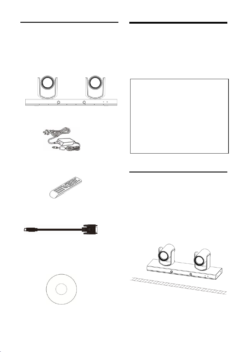
List Of Parts & Accessories
When you open the box, check all accessories
according to the packing list.
Camera (1)
Power Adapter (1)
Remote Controller (1)
RS-232 Control Cable (1)
INSTALLATION
The camera has 2 installation types: desktop,
wall (optional) installations.
Note
- Before installing, make sure there is
enough space to install the camera and
its parts.
- Make sure the installed place is strong
and safe enough to hold the camera and
relative parts, it is suggested that the
installed place can withstand 4 times the
weight of the camera and its relative
parts.
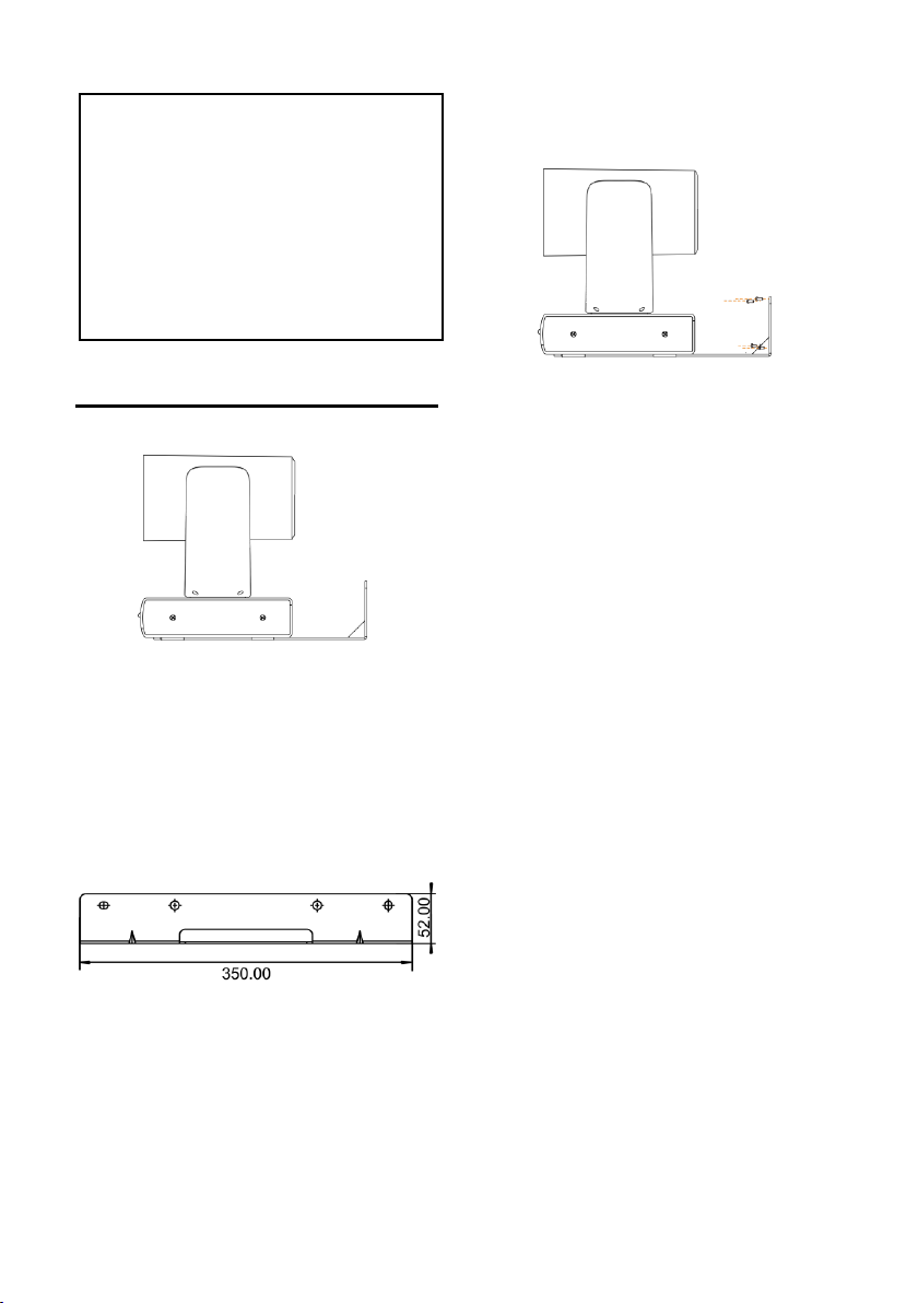
Desktop Mount Installation
Put the camera on a flat surface. In case
1.
the camera has to be placed on an
inclined surface, make sure the cline
angle is less than 15 degrees to ensure
proper pan /tilt operation.
Software Disc (1)
Page 12
Note
Take effective measures to avoid camera
from dropping.
Do not grab the camera head when
carrying.
Do not rotate the camera head with
hand. It may cause malfunction to
the camera.
Wall Mount Installation
According to diameter and position of the
1.
4 installation holes (As shown below) on
the bracket, drill 4 holes on the wall and fix
the bracket onto the wall by using 4
screws which should be prepared by you.
camera is tightly fixed onto the
bracket before your hands leave the
camera.
Before fixing the camera, set the DIP
2.
switches of the camera correctly.
Use inch screws to fix the camera on the
3.
bracket, fix the limit screw according to
actual requirement, and make sure the
6
Page 13
DIP Switches Settings
SW
DIP No.
1 2 3
4
Video
Format
OFF
OFF
OFF
OFF
1080p60
ON
OFF
OFF
OFF
1080pP5
OFF
ON
OFF
OFF
1080i60
ON
ON
OFF
OFF
1080i50
OFF
OFF
ON
OFF
720p60
ON
OFF
ON
OFF
720p50
OFF
ON
ON
OFF
1080p30
ON
ON
ON
OFF
1080p25
Before installing and operating the camera,
set the camera video output format
through DIP switches.
When No.1~4 is all ON, camera video format
can be programmed by OSD menu. Please
refer to page37.
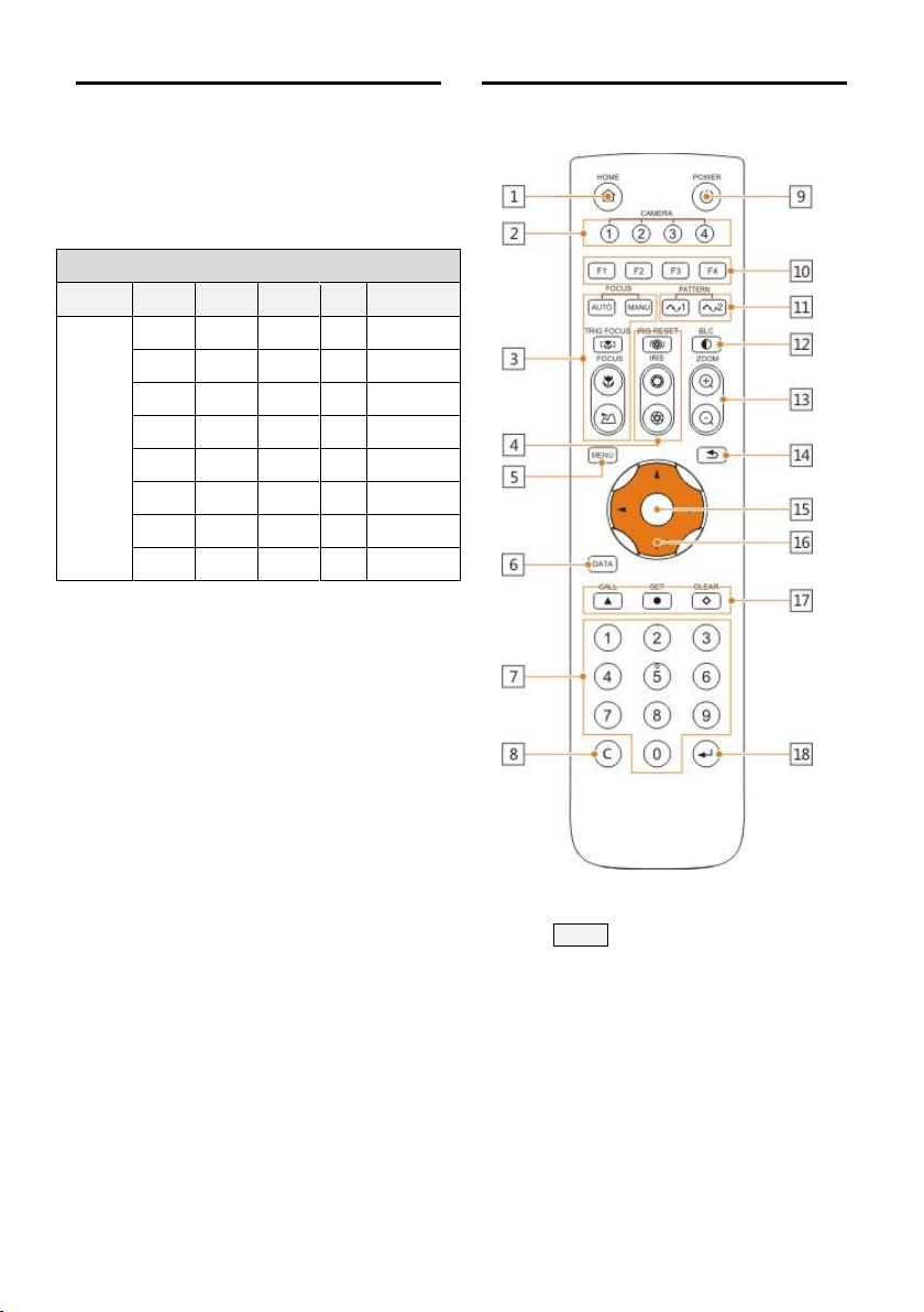
Remote Controller
1 HOME
Press HOME button, camera moves to
initial position where both pan and tilt
angle is zero.
2 Camera Selection Button
Used to switch among 4 cameras, press 1-4
number buttons to control cameras with 1-4
addresses respectively. For example, press
7
Page 14
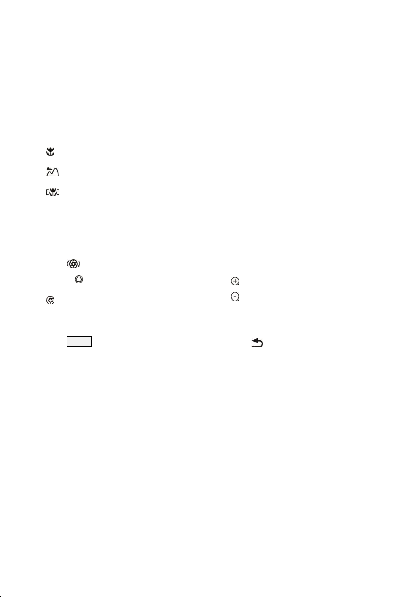
button 1 to control the camera with address 1.
3 Focus
Press “AUTO” button to switch to Auto
Focus, press “MANU” button to switch to
Manual Focus mode.
10 Reserved buttons(F1, F2, F3, F4)
Press the "F1" button, start the trace, press
the "F2" button, stop tracking, press the
"F3" button, SDI/HDMI output scene switch,
"F4" button for the retention button, no
function.
“ ”button to Focus Near
“
”button to Focus Far
“
”button to Auto Focus once every time
it is pressed, then switch back to Manual
Focus mode.
4 Iris
Press“ ”button to reset iris value to
default. “ ”button to Iris Open
“ ”button to Iris Close.
5 Menu
Press MENU button to enter / exit menu.
6 Data
The button is reserved for future use.
7 Number Keys
Used to input numbers, for example, preset
number.
8 Cancel
The button is reserved for future use.
9 Power
After the camera has been connected to
power source, in none-menu status, press
this button to turn on / off the camera.
11 Pattern
The button is reserved for future use.
12 BLC
Used to open / close back light
compensation.
13 Zoom
Used to adjust zooming times.
“ ”button to zoom in
“ ”button to zoom out.
14 Back
Press “ ” button to go back to previous
menu.
15 OK
In None-menu status: press this button
to switch among pan / tilt control speeds.
In Menu status: get into relative
menu option after it has been
selected.
16 Direction / Menu Operation
In None-menu status, press these four
buttons to pan left/right and tilt up/
down.
8
Page 15
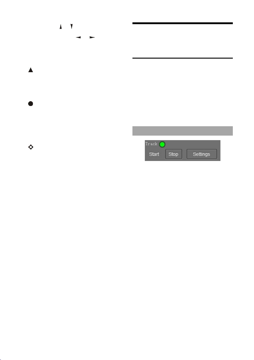
In Menu status: or button to select
among menu options, or to change
option / value.
SETTING
17 Preset Setting
“ ” button to call a preset.
Input number key(s), and then press this
button to call a preset.
“ ”button to set a preset.
Move the camera to a specific position,
adjust focus value and etc, and then press
this button to set a preset.
“ ”button to clear a preset.
Input number key(s), and then press this
button to clear a preset.
18 Enter
The button is reserved for future use.
Software Connection
Take out Disc from the camera package,
install “iSmart CMS” from the disc on your PC,
turn on “iSmart CMS” , connect and add
camera to the management device list, and
enter into the main interface. Select one of a
camera to do the following settings:
Tracking Settings
Start: Turn on tracking, use controller or
software to call preset 80 can also turn on
tracking.
Stop: Turn off tracking, use controller or
software to call preset 81 can also turn off
tracking.
Settings: Click this button to get into
detailed tracking parameters for
configuration.
Once this button is clicked, main stream will
automatically switch from tracking camera to
full view camera. Once configuration is
completed, main stream will return to
tracking camera again.
9
Page 16
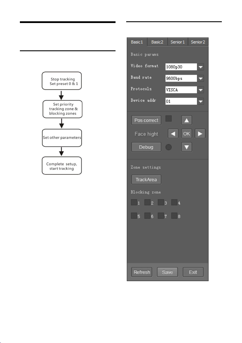
10
PARAMETERS SETTING
Setting Process
Preset 0 and Preset 1 are set as presets of full
view image, or as presets of any zoom or
position. When there is no target, camera will
return to preset 0 or preset 1. Please refer to
Basic Setting.
Parameter Setting
Page 17

11
Page 18

Basic Parameters Setting
The factory default setting of the camera is 1
(address), 9600bps, VISCA protocol, 1080p30
resolution for tracking camera and full view
camera.
Position Calibration
Adjust object’s position in the video when he/
she is not in the center of image.
Note: The position has been adjusted to the
best value before leaving the factory, do not
change it until it is necessary.
Debug
Enable and disable the rectangles of full view
camera, showing been detected targets.
Zone Settings
Track Area: The area that meeting attendees
will move within.
Blocking zones: There are 8 blocking zones
shown in green rectangle, they can be
configured independently. The moving
objects inside the blocking zones of the full
view camera will not be detected and tracked
while the tracking camera still tracks the
lecturer.
Tracking Params
Tracking Sens: Set sensitivity of tracking
enable to detect and track. High sensitivity
easily, and not lose the object.
Zoom Sens: It defines how big the movement
range will trigger camera to PTZ to frame
after object is tracked.
Zoom Limit: Higher value enables higher
zoom times of the object in the image.
The tracking zone and blocking zones (up,
bottom, left and right limits) have to be set.
The tracking zone is an area where the
targets are.
12
Page 19

13
Target Lost Action: Used to define the action
to be performed if the camera loses the
tracked object for a period of time.
Power On State: The action to be performed
when the camera is powered on.
(Co
de Send) Mode: Choose to send codes via
network or serial port;
onnect Protocol: Once “Network” is chosen
C
as “Mode”, choose TCP or UDP as
communication protocol.
(Tracking Camera) As: Once “Network” is
chosen as “Mode”, choose “Client” to actively
communicate with recorder, choose “Server”
to await to be communicated from recorder.
Director IP and Port: Once “Network” is
chosen as “Mode”, configure recorder’s IP
address and Port at these two frames.
Page 20
CMS Application Software Guide
Network Connection
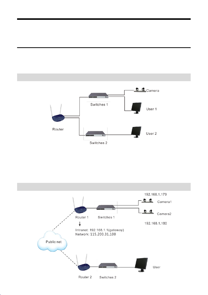
Connect the camera to network with an Ethernet cable, power on the camera.
LAN Connection
Please refer to the above diagram, user1 and user 2 are in the same router, they are considered as in
the same LAN, connect the camera to the same LAN as where the PC is, and refer to below
instructions as how to use the application software, then the camera can be found and connected
from the online device list.
WAN Connection
14
Page 21

15
Please refer to the above diagram, user and the camera are in different routers, they are
considered as in a WAN; in this condition, application software iSmartCMS can not search and find
the camera automatically. User can still connect after below conditions are satisfied: (1) Set
camera’s IP address as static IP address (2) Router of the LAN where camera is connected supports
Port Mapping. (3) Router of the LAN where camera is connected has fixed public IP address. Follow
below steps to connect:
1.
Set camera’s IP address in LAN: Connect user PC to the LAN (Router 1) where the camera is
connected according to LAN connection instructions, use application software iSmartCMS to
search and find the camera, then add it to manage; then set camera’s IP address in the same
network segment as the router 1. Camera’s gateway is usually set at Router 1’s LAN IP address, for
example, 192.168.1.1, then camera’s IP address can be set as for example 192.168.1.179 or 192.168.1.180
as long as they are in the same network segment.
2.
Route Mapping: User PC logs into router configuration menu, gets into “Port Mapping” (router
management authorization may be required); refer to below picture, DO NOT tick “Do not apply this
rule”, from first frame under “External port”, input any number from 1~65535, but preferred to be set
at more than 10000 like 10200 so there will be less port conflict possibility. From “Internal IP”, input
the camera1’s IP address 192.168.1.179, from first frame of “Internal Port”, input 3478, (all cameras use
this same port number). “Protocol” and “Mapping Line” can be default, from “Note”, input “Camera
1’s mapping port” or something to understand.
Page 22

3. Access from external network: Router 1's public IP address is 115.200.31.100, for example, go
through the above steps one and two, WAN users under router 2 can access camera 1 through IP
address 115.200.31.100 + port 10200. Then, in WAN, the mapping of camera 1 and (IP 115.200.31.100 +
port 10200) is established. Camera 2 can use another external port such as 10320, so mapping of
camera 2 with (IP 115.200.31.100 + port 10320) is established. In the
"Managed Device" of the client software iSmart CMS, click "+ Add", enter the IP address
115.200.31.100 and port 10200 and other information, then the camera 1 can be accessed and
controlled.
16
Page 23
17
Client Software Instruction
Search And List The Camera
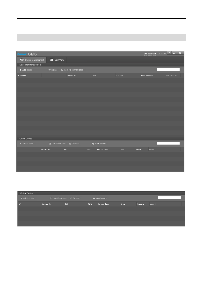
Install and open the client software in PC, enter the main interface:
If the camera and PC are in the same LAN, click “Start Search”, then searching starts and all online
devices will be listed, as the picture shown below:
o modify the device IP address, input the IP address, mask, gateway in the “Modify Network”
T
column.
Page 24

To control and preview a camera, first choose the device, modify its IP address as the IP address of
the same LAN, then click “Add to Client” as the picture shown below.
Please check that all IP addresses are in the same LAN.
Remote Configuration
Choose the camera in the device list, click “Remote Configuration” in the column to upgrade or
config the camera.
18
Page 25

Streaming
Stream type: Set the parameters of main stream, sub stream, third stream, fourth stream.
Resolution: Set among 1080P (1920*1080), HD720P (1280*720), D1 & QVGA (320*240), choose
resolutions based on actual requirements and capability of device. The higher the
resolution is, the better network requirements will be needed.
Max rate: Configure max stream rate or adjustable stream rate.
Frame rate: Choose from different frame per second.
Key frame interval: Configure the number of frames between the two key frames. The larger the
key frame interval is, the smaller the fluctuation of the byte will be, but the image quality is
relatively poor. Vice versa, the larger the fluctuation of the byte will be, the higher the image
quality will be.
Video coding type: Choose H.264 or H.265.
Encode level: Choose from Base, Main and High.
19
Page 26
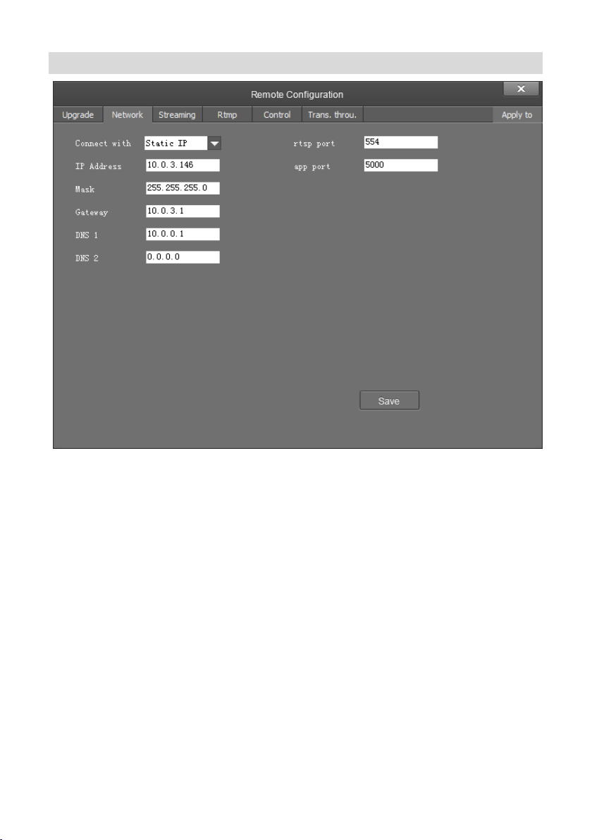
Network
Connect with: Please choose from Static IP or dynamic IP address.
IP address: Input IP address for the camera.
Mask: Input mask address for the camera.
Gateway: Input gateway IP address.
DNS 1: Server-prior, input DNS address for the device.
DNS 2: It will be used in case DNS1 server is not working.
Port: Streaming port (RTSP) and application port (SDK connection) can be configured. The
range of stream ports is 3479~7999 and 554, default is 554. The range of application ports is
3479~7999, default is 5002.
Click the “Save” button after setting is completed.
Camera will connect to ethernet after above-mentioned operations.
20
Page 27

21
RTMP
In RTMP1 and RTMP2, main stream, sub stream can be chosen to stream.
Page 28
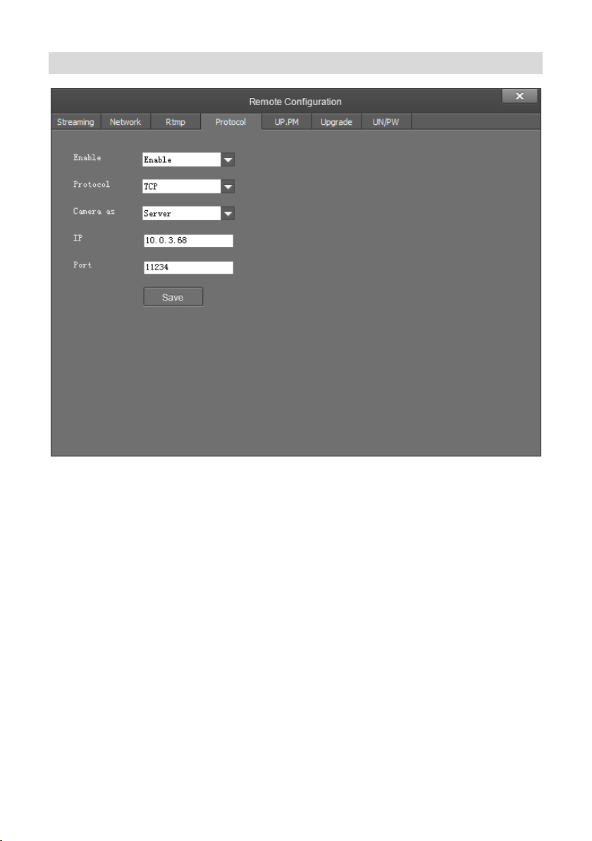
Protocol
●
Enable / Disable: Enable / disable transparent transmission.
●
Protocol: Choose TCP or UDP protocols.
●
Camera as: Choose Client or Server.
IP: When the camera is set as client, the IP address of the transmitted camera is needed. When
●
the camera is set as server, the IP address can be left as black.
●
Port: Choose from 1-65535 as transparent transmission port.
22
Page 29
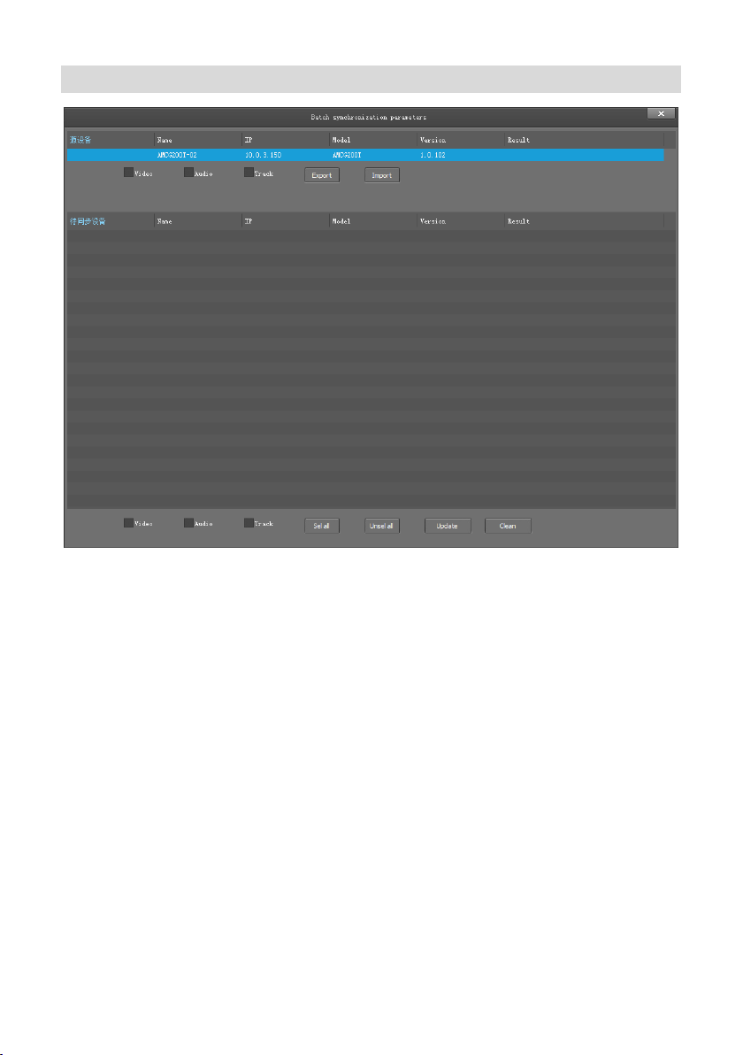
UP PM
After selecting the same model of the device to be synchronized that is currently managed and
unchecked, tick any or more of the video parameters, audio parameters, and trace parameters,
and when you click the sync parameters, the device that you are currently synchronizing will
synchronize with the source device parameters.
Parameter import, parameter export: Only for source device operations, you can export camera
parameters to a file, or you can import parameters from a file into the camera.
Bulk synchronization: Only for synchronous device operations.
23
Page 30
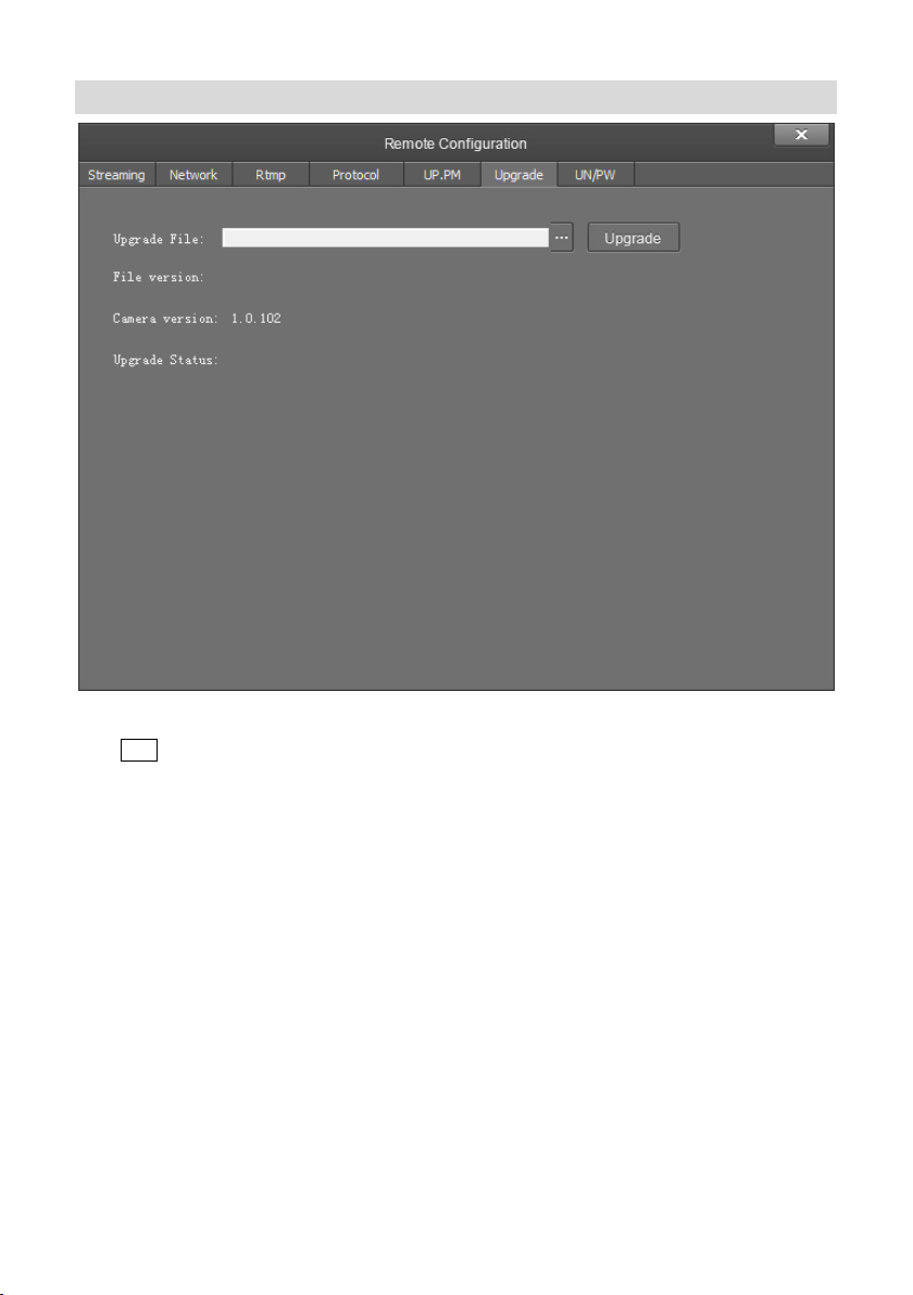
Upgrade
Click “Upgrade” menu to enter the main interface, as the picture shown above.
to search and load the updating firmware, then click “Upgrade” to start upgrading. Do
Click …
not power off the camera during upgrading. After upgrading is completed, camera will reboot.
24
Page 31
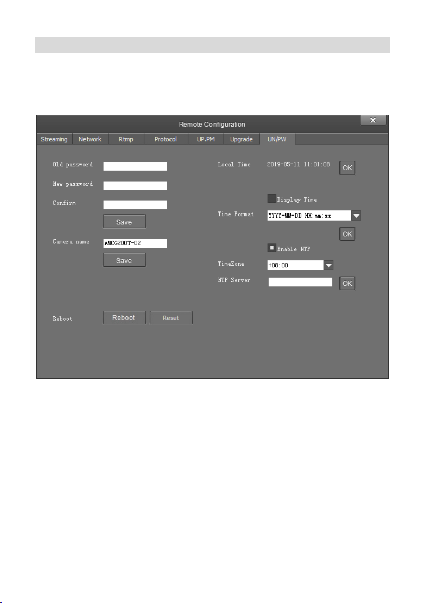
UP/PW
Password setting: When a password is required, the camera can be accessed only after a
●
correct password is input.
Reboot: Reboot the camera.
25
Page 32

Preview
Click “Main View” to get into camera control and preview part as below.
This interface includes three main parts: Device List, Device Control, Video Preview
●
Device: It displays all online cameras added to “Device Management”.
26
Page 33
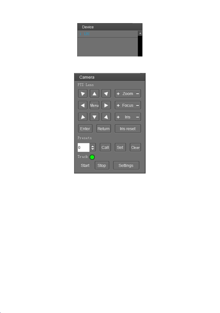
Device Control: Get control of the selected camera (camera name in blue).
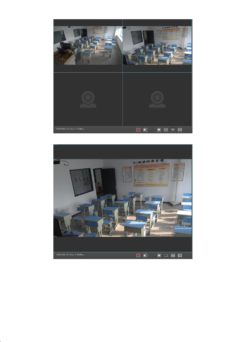
Video Preview: Double click the camera in the list, main camera stream will be displayed in the
preview window; or right click the selected camera from the left column to get its main or
substream video. Video preview mode can be single video or four video’s, when in four video’s
mode, select one of the four video’s then choose the bottom right icon to enlarge this selected
video to a big single window.
27
Page 34
28
Page 35
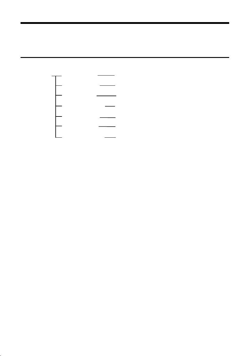
MENU SETTINGS
Menu Configuration
<VIDEO> SHARPNESS
Refer
Page33
BRIGHTNESS
CONTRAST
GAMMA MODE
2DNR LEVEL
3DNR LEVEL
FV LDC LEVEL
1, 2, 3, 4, 5, 6, 7, 8, 9, 10, 11, 12, 13, 14, 15 1, 2,
3, 4, 5, 6, 7, 8, 9, 10, 11, 12, 13, 14
1, 2, 3, 4, 5, 6, 7, 8, 9, 10, 11, 12, 13, 14
0, 1, 2, 3, 4,
1, 2, 3, 4, 5, 6, 7 OFF
1, 2, 3, 4, 5, 6, 7 OFF
1, 2, 3, 4, 5 OFF
29
Page 36

<EXPOSURE>
Refer to Page
33
MODE
FULL AUTO
MANUAL
GAIN
0, +2, +4, +6, +8, +10,
+12, +14, +16, +18,
+20, +22, +24, +26,
+28,+30
SPEED
1/1, 1/2, 1/3, 1/6, 1/12, 1/25,
1/50, 1/75, 1/100, 1/120,
1/150, 1/215, 1/300, 1/425,
1/600, 1/1000,1/1250,
1/1750, 1/2500, 1/3500,
1/6000, 1/10000
IRIS
F14, F11, F9.6, F8, F6.8,
F5.6, F4.8, F4, F3.4, F2.8,
F2.4, F2, F1.6, CLOSE
SHUTTER PRI
SPEED
1/1, 1/2, 1/3, 1/6, 1/12, 1/25,
1/50, 1/75, 1/100, 1/120,
1/150, 1/215, 1/300, 1/425,
1/600, 1/1000,1/1250,
1/1750, 1/2500, 1/3500,
1/6000, 1/10000
IRIS PRI
IRIS
F14, F11, F9.6, F8, F6.8,
F5.6, F4.8, F4, F3.4, F2.8,
F2.4, F2, F1.6, CLOSE
BRIGHT PRI
BRIGHT
1, 2, 3, 4, 5, 6, 7
、
EX-COMP
ON
OFF
LEVEL
7, -6, -5, -4, -3, -2, -1, 0, +1,
+2, +3, +4, +5, +6, +7
BLC
ON
OFF
ANTI –FLICKER OFF, 50HZ, 60HZ
< COLOR >
Refer to Page 34
WB MODE
AUTO, ATW, ONE PUSH, INDOOR, OUTDOOR,
MANUAL, SODIUM LAMP, FLUO LAMP, COLOR
TEMP
SATURATION
1, 2, 3, 4, 5, 6, 7, 8, 9, 10, 11, 12, 13, 14
HUE
1, 2, 3, 4, 5, 6, 7, 8, 9, 10, 11, 12, 13, 14
30
Page 37

<PAN TILT ZOOM>
Refer to Page 34
PAN/TILT SPEED
1, 2, 3, 4, 5, 6, 7, 8
PTZ TRIG AF
ON, OFF
RATIO SPEED
ON, OFF
<SYSTEM>
Refer to Page
35
ADDRESS 1, 2, 3, 4, 5, 6
PROTOCOL VISCA
BAUD RATE 9600
VIDEO FORMAT 1080p60, 1080p50, 1080i60,
1080i50, 1080p30, 1080p25,
720p60, 720p50
<STATUS>
Refer to Page
35
ADDRESS 1
PROTOCOL VISCA
BAUD RATE 9600
VIDEO FORMAT 1080p30
FIRMWARE VER.F 1.0.1016BETA
FIRMWARE VER.P 1.0.2016BETA
FIRMWARE VER.A 1.1.3000
<RESTORE DEFAULTS>
Refer to Page 35
31
Page 38
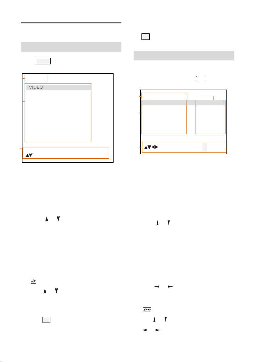
Menu Explanation
<EXPOSURE>
MODE FULL AUTO
EXP-COM ON
BLC ON
ANTI -FLICKER OFF
[ ]SELECT []BACK
❶
❷
❸
❶ ❸
❷
❹
Main Menu
MENU
Press
<MENU>
VIDEO
EXPOSURE
COLOR
PAN TILT ZOOM
SYSTEM
STATUS
RESTORE DEFAULTS
[ ]SELECT [OK] NEXT []EXIT
button to enter / exit menu.
“[OK] EXIT” indicates it is possible to press
OK button to exit menu.
Submenus
From main menu, navigate to select
<EXPOSURE> menu, press OK to enter
❶ Menu Hint
It displays currently selected menu option.
❷ Menu Options
It displays options under current menu
hint. Press or button to select among
menu options, once font of options turned
from white color to yellow color, it indicates
the menu has been elected, press OK
button to get
❸ Prompt Message
“
press
options.
“[OK]NEXT” indicates it is possible to
press OK button to enter next level menu.
into this menu.
SELECT” indicates it is possible to
or
button to select menu
32
❶ Menu Hint
It displays currently selected menu option.
❷ Menu Options
It displays options under current menu
hint.
Press or button to select among
menu options, once font of options turned
from white color to yellow color, it
indicates the menu has been elected,
press OK button to get into this menu.
❸
Manual Exposure
Press
button to change value.
or
❹ Prompt Message
“ SELECT” indicates it is possible to
press or to select menu options, press
or to change value
Page 39
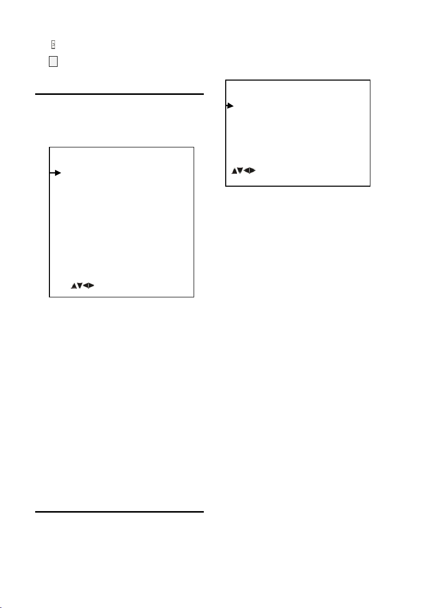
“ BACK” indicates it is possible to press
<VIDEO>
SHARPNESS 8
BRIGHTNESS 7
CONTRAST 2
GAMMA MODE 0
2DNR LEVEL OFF
3DNR LEVEL OFF
WIDE DYNAMIC OFF
[ ]SELECT []BACK
<EXPOSURE>
MODE FULL AUTO
EXP-COMP ON
BLC ON
ANTI-FLICKER OFF
[ ]SELECT []BACK
to return to previous menu.
Video
VIDEO menu is used to change video value.
SHARPNESS: 1, 2, 3, 4, 5, 6, 7, 8, 9, 10, 11, 12, 13,
14, 15.
BRIGHTNESS: 1, 2, 3, 4, 5, 6, 7, 8, 9, 10, 11, 12, 13,
14.
CONTRAST: 1, 2, 3, 4, 5, 6, 7, 8, 9, 10, 11, 12, 13, 14.
GAMMA MODE: 0, 1, 2, 3, 4.
2DNR LEVEL: 1, 2, 3, 4, 5, 6, 7 OFF.
3DNR LEVEL 1, 2, 3, 4, 5, 6, 7 OFF.
WIDE DYNAMIC: 1, 2, 3, 4, 5, OFF.
Exposure
EXPOSURE menu is used to adjust exposure
value.
MODE:
FULL AUTO: Gain, Shutter Speed and Iris
value are adjusted automatically accordingly
to working environment.
MANUAL: Manually adjust Gain, Shutter
Speed and Iris.
GAIN: 0, +2, +4, +6, +8, +10, +12, +14, +16, +18,
+20, +22, +24, +26, +28, +29, +30.
SPEED: 1/1, 1/2, 1/3, 1/6, 1/12, 1/25, 1/50, 1/75,
1/100, 1/120, 1/150, 1/215, 1/300, 1/425, 1/600,
1/1000, 1/1250, 1/1750,
1/2500, 1/3500, 1/6000, 1/10000s.
IRIS: F14, F11, F9.6, F8, F6.8, F5.6, F4.8, F4,
F3.4, F2.8, F2.4, F2, F1.6, CLOSE.
SHUTTER PRI: Gain and Iris value are
adjusted automatically according to
working environment; shutter speed value
is adjustable manually.
SPEED: 1/1, 1/2, 1/3, 1/6, 1/12, 1/25, 1/50, 1/75,
1/100, 1/120, 1/150, 1/215, 1/300, 1/425, 1/600,
1/1000, 1/1250, 1/1750, 1/2500, 1/3500, 1/6000,
1/10000s.
33
Page 40

IRIS PRI: Gain and shutter speed value are
< COLOR >
WB MODE MANUAL
R . GAIN 7
B . GAIN 7
SATURATION 7
HUE 7
[ ]SELECT []BACK
adjusted automatically according to
working environment; Iris value is adjustable
manually.
IRIS: F14, F11, F9.6, F8, F6.8, F5.6, F4.8, F4, F3.4,
F2.8, F2.4, F2, F1.6, CLOSE.
BRIGHT PRI: Manually adjust the video
brightness.
BRIGHT: 1, 2, 3, 4, 5, 6, 7.
EXP-COMP: Once EXP-COMP is set as On,
below level options become available -7, -6,
-5, -4, -3, -2, -1, 0, +1, +2, +3, +4, +5, +6, +7
+7 is the maximum compensation value for
bright, -7 is the maximum compensation
value for dark.
BLC: ON, OFF.
Backlight compensation (BLC) is video gain
done automatically to correct the exposure
of subjects that are in front of a bright light
source.
ANTI-FLICKER (OFF, 50Hz, 60Hz): To avoid
video flicker at power systems of different
frequency.
WB MODE: AUTO, ATW (auto tracking), ONE
PUSH, INDOOR, OUTDOOR, MANUAL,
SODIUM LAMP, FLUO LAMP, COLOR TEMP.
“ONE PUSH”: In “ONE PUSH TRIGGER”
mode, aim the camera at a pure white object
(say a white paper), then press OK button.
“AUTO” mode: R.GAIN, G.GAIN and B.Gain
can be chosen from -7~+7.
“MANUAL” mode: R.GAIN and B. GAIN value
can be chosen from 0~255.
SATURATION: 1, 2, 3, 4, 5, 6, 7, 8, 9, 10, 11, 12, 13,
14.
Color
COLOR menu is used to adjust color related
values. Available options:
34
HUE: 1, 2, 3, 4, 5, 6, 7, 8, 9, 10, 11, 12, 13, 14.
Pan/Tilt/Zoom
PAN/TILT/ZOOM is used to change
pan/tilt/zoom value, available options:
Page 41

PAN/TILT SPEED: 1, 2, 3, 4, 5, 6, 7, 8 the
< RESTORE DEFAULTS>
PRESS CONFIRM
PRESS CANCEL
< STATUS>
ADDRESS 1
PROTOCOL VISCA
BAUD RATE 9600
FIRMWARE VER.F 1.0.1016BETA
FIRMWARE VER. P 1.0.2016BETA
FIRMWARE VER.PA 1.1.3000
[]BACK
<SYSTEM>
ADDRESS 1
PROTOCOL VISCA
BAUD RATE 9600
VIDEO FORMAT 1080p30
[ ]SELECT []BACK
<PAN TILT ZOOM>
PAN/TILT SPEED 8
PTZ TRIG AF OFF
RATIO SPEED ON
[ ]SELECT []BACK
bigger the number is, the faster the speed is.
PTZ TRIG AF: Turn ON / OFF the auto focus
when the camera pans / tilts / zooms.
RATIO SPEED (ON, OFF): Set the relation of
PT speed as per zoom time. When it’s on, PTZ
speed will be faster when zoom time is
bigger.
Status
Display information (address, protocol, baud
rate, IR address, video format, mount mode,
image and firmware version) of the current
camera.
System
ADDRESS: 1, 2, 3, 4, 5, 6.
PROTOCOL: VISCA.
BAUD RATE: 9600.
VIDEO FORMAT: 1080p60, 1080p50,
1080p30, 1080p25, 1080i60, 1080i50,
720p60, 720p50.
Restore Defaults
RESTORE DEFAULTS option is used to reset
all menus to default value.
Press OK to confirm or press
and return to previous menu.
to cancel
35
Page 42
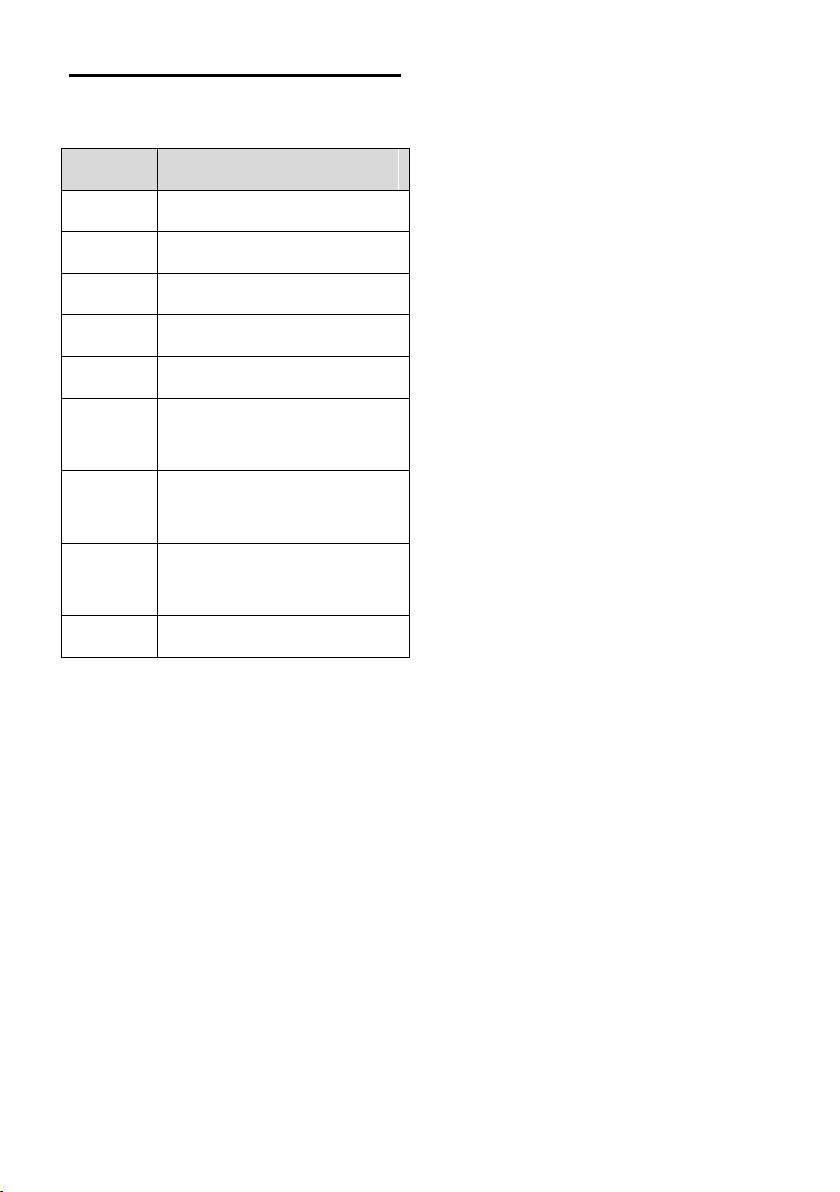
List Of Special Preset Commands
Preset No Function
80
81
95
96
99
121
122
123
125 Camera calibration
Turn on tracking
Turn off tracking
Turn on/off OSD
Clear all presets(0-64)
Reboot system
SDI or HDMI output
tracking view 1
SDI or HDMI output
tracking view 2
SDI or HDMI output
tracking dual screen
36
Page 43
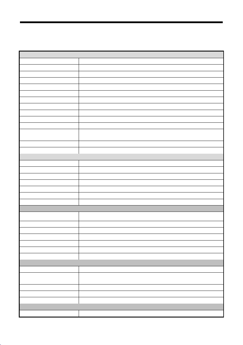
ANNEX 1 TECHNICAL SPECIFICATIONS
Tracking Camera
Image Sensor 1/2.8" CMOS, 2.14 megapixel
Focal Lens f=3.9mm-46.8mm
Iris F1.6-F2.8
Optical Zoom 12x
Digital Zoom 12x
Horizontal Viewing Angle 72.5°-6.3°
Focus System Auto, Manual, PTZ Trigger, One Push Trigger
Exposure Control Auto, Manual, Shutter Priority, Iris Priority
Min. Illumination 1.0Lux @ (F1.8, AGC ON)
Shutter Speed 1/1 to 1/10,000s
Gain Auto /Manual
White Balance
S/N ≥50dB
Menu English
Full-View Camera
Image Sensor 1/2.8" CMOS
Effective Pixels 2.14MP
Focus Manual
Exposure Control Auto
White Balance Auto
Focal distance 2.4mm
Viewing Angle Horizontal: 86°, Vertical: 52°
PTZ
Pan Angle
Tilt Angle -30°~+90°
Pan Speed 0.1°~120°/S
Tilt Speed 0.1°~90°/S
Preset Number 256
Protocol VISCA
Network RJ45 (100M, self-adaptive)
HD Video
Video Output 3G-SDI, HDMI
Video Format
Audio Input 2 x LINE IN, including one channel with EC
Audio Output 1 x LINE OUT
Control Interface RS-232
NETWORK
Resolution Max Support 1920*1080@60fps
Auto, Indoor, Outdoor, One Push, Manual, Auto Tracking, Color
Temp
-90°~+90°
1080p60, 1080i60, 1080p30, 720p60
1080p50, 1080i50, 1080p25, 720p50
37
Page 44

Image Compression H.264/H.265
Audio Compression AAC
Protocols ONVIF, RTSP, RTMP, HTTP, TCP, UDP, RTP
Dual Stream Support
General
Address 1-6
Power DC12V
Power Consumption <24W
Operating Temperature 0°C~+40°C
Storage Temperature -20°C~+60°C
Dimensions (W×H×D)
Body color Grey
500mm×137mm×164mm
38
Page 45
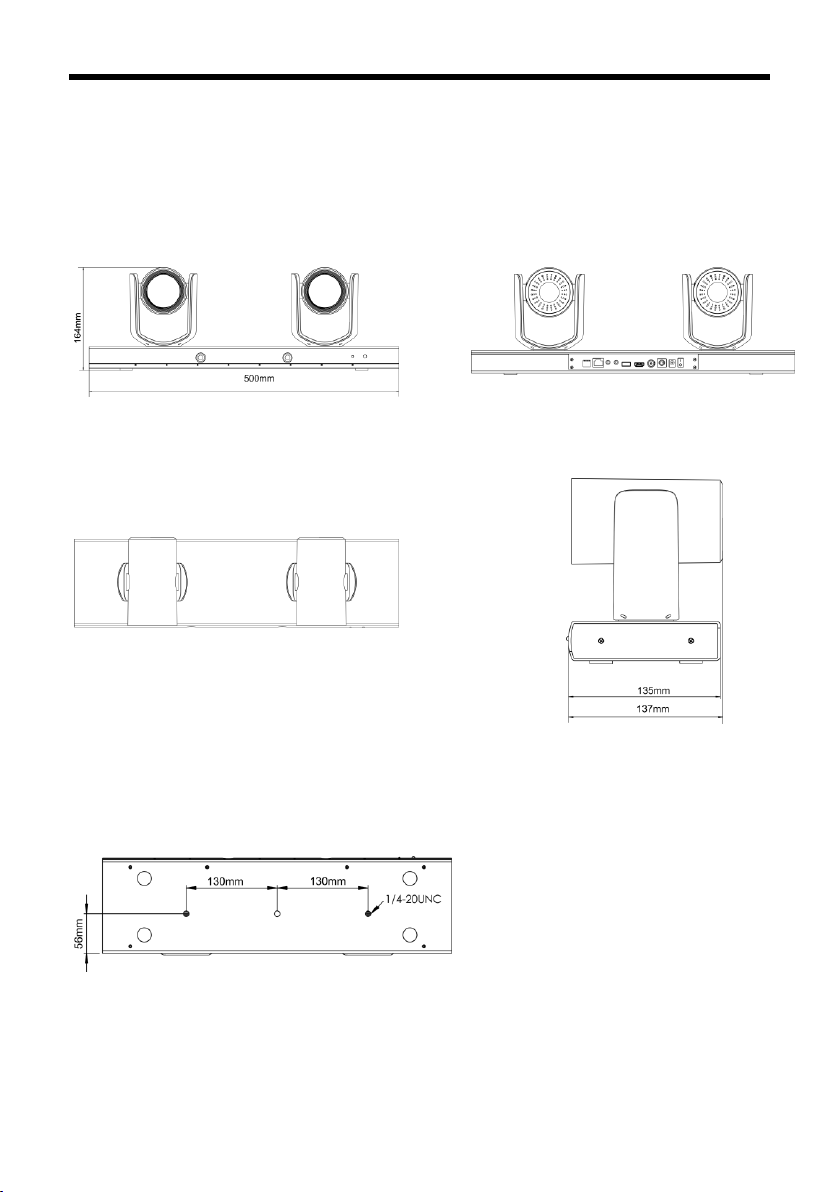
ANNEX 2 SIZE AND DIMENSION
Front
Top
Bottom
Rear
Side
39
Page 46

TROUBLESHOOTING
Problem Possible Cause Solution
Power supply failure Check power supply
No action or image
after powered on
No self-testing after
powered on, or
with motor noise
Power adapter damaged Replace power adapter
Power cable connection got loosen Check & reconnect
Power cable is too long Use a shorter cable
Power adapter damaged Replace power adapter
Mechanical failure Repair
Not controllable
from remote
controller
After power on, selftest successfully,
but not controllable
Video loss when
pans / tilts / zooms
Video captured after
connected to digital
video interface of a
capture device is not
good as the video
captured after
connected directly
analog video
interface of the
capture device
Low battery of remote controller Change battery for remote controller
Exceed remote control distance Control within distance of 8M
Wrong address / protocol / baud rate Check & set again
Wrong connection or open circuit
of RS-232 cable
Power cable is too long Use a shorter cable
Power adapter damaged Replace power adapter
Video cable not properly connected Replace with a good video cable
Different video capture devices have
different video capturing
performance, image quality maybe
worse after it has been converted
from analog to digital
Check & reconnect
Consult video capture device
supplier for more information
40
Page 47

Page 48

The user manual is only for a reference, if there are
any changes or differences, please ask for the latest
version from your supplier
 Loading...