


Installation and
Configuration Guide
SMART Board™ 600i Series
Interactive Whiteboard System

Product Registration
If you register your SMART product, we’ll notify you of new features and
software upgrades.
Register online at
www.smarttech.com/registration.
Keep the following information available, in case you need to contact
Technical Support:
Serial Number ____________________________________________
Date of Purchase _________________________________________
FCC Warning
This equipment has been tested and found to comply with the limits for a Class A digital device, pur suant to Part 15 of the FCC
Rules. These limits are designed to provide reasonable protection against harmful interference when the equipment is operated
in a commercial environment. This equipment generates, uses and can radiate radio frequency energy and, if not installed and
used in accordance with the manufac turer ’s ins truc tions., may cause harmful interference to radio communications. Operation of
this equipment in a residential area is likely to cause harmful interference in which case the user will be required to correct the
interference at his own expense.
Trademark Notice
SMART Board, smart tech, Notebook, Unifi and the SMART logo are trademarks or registered trademarks of SMART Technologies ULC
in the U.S. and/or other countries. Microsof t and Windows are either trademarks or registered trademarks of Microsoft Corporation in
the U.S. and/or other countries. DLP and DMD are registered trademarks of Texas Instruments. Vikuiti is a trademark of 3M company.
All other third-party product and company names may be the trademarks of their respective owners.
Copyright Notice
© 200 6–2007 SMART Technologies ULC. All rights reserved. No par t of this publication may be reproduced, transmitted, transcribed,
stored in a retrieval system or translated into any language in any form by any means without the prior written consent of
SMART Technologies ULC. Information in this manual is subject to change without notice and does not repre sent a commitment on
the part of SMART.
Patent No. US5 448263; US6141000; US6326954; US6337681; US6741267; US6747636; US7151533; and CA 2058219. Other patents
pending.
11/2007

Important Information
NOTE: If you own a SMART product other than a SMART Board™ 600i series interactive
whiteboard system, refer to the installation manual that came with your product for relevant
warnings and maintenance instructions.
Before you install and use the 600i SMART Board interactive whiteboard system, please read
and understand the safety warnings and precautions in this guide. These safety warnings and
precautions describe the safe and correct operation of the 600i interactive whiteboard system
and its accessories, helping you prevent injuries and equipment damage. You must always
ensure that the system is being used correctly.
In this document, “600i series interactive whiteboard system” refers to the interactive
whiteboard and its Unifi™ 35 projector, accessories and options. Please also read the safety
warnings and precautions that came with the peripheral products, such as the computer.
The Unifi 35 projector included with your new 600i interactive whiteboard system is designed
to work only with SMART Board Model 660 or 680 interactive whiteboards.
Safety Warnings
WARNING
Do not stare into the beam of light created by the projector. Instruct children not
to look in the direction of, or stare at, this beam of light.
WARNING
WARNING
WARNING
WARNING
Failure to follow the installation instructions included with the 600i series
interactive whiteboard system (and found in this guide) could result in personal
injury or damage to the product.
To reduce the risk of fire or electric shock, do not expose any component of the
600i series interactive whiteboard system to rain or moisture.
Two people are required to mount the projector or the interactive whiteboard on
a wall because they may be too heavy for one person to maneuver onto their
wall-mounting brackets.
Do not climb (or allow children to climb) on any
part of the wall-mounted SMART Board 600i
series interactive whiteboard system.
Do not climb on, hang from, or suspend objects
from the Unifi 35 projector’s arm.
Climbing on the interactive whiteboard or projector
arm could result in personal injury or product
damage.
99-00737-25 Rev A0 Important Information i

WARNING
Do not attempt to service the projector other than performing routine lamp
replacement. Service should only be performed by an authorized service
provider. Aside from the lamp module, there are no user serviceable parts
inside the unit.
Do not remove any screws other than those specified in the lamp replacement
instructions.
Other Precautions
To ensure operating safety and to avoid product damage, observe the following precautions.
• Do not set up or use the interactive whiteboard in an area with excessive levels of dust,
humidity and smoke.
• Do not leave cables on the floor. If you must run a cable over the floor, lay the cable in a
flat, straight line, and secure it to the floor with tape or a cable management strip in a
contrasting color. Handle cables carefully and don’t bend them excessively.
• Do not add extra weight or apply pressure to the Unifi 35 projector arm, the wall-mounted
interactive whiteboard or its pen tray. SMART designed the brackets to support only the
weight of the components during normal use.
• To reduce the risk associated with leaking batteries:
– use only AA type batteries
– do not mix used and new batteries
– orient the battery’s plus (+) and minus (-) terminals according to the markings found on
the remote control
– do not leave the batteries in the remote control for an extended period
– do not heat, disassemble, short or recharge the batteries, or expose them to fire or
high temperature
– avoid eye and skin contact if batteries have leaked
– dispose of exhausted batteries and product components in accordance with applicable
regulations
• If the interactive whiteboard system requires replacement parts, make sure the service
technician uses replacement parts specified by SMART Technologies, or parts with the
same characteristics as the original.
Transporting the 600i Interactive Whiteboard System
If you need to ship any part of your interactive whiteboard system, repack it with the original
packaging. If the original packaging is no longer available, you may purchase replacement
packaging from SMART Technical Support (see page 73 for contact information).
If you prefer to use your own packaging materials, make sure you adequately protect the unit.
Ship the interactive whiteboard in an upright position to deter shippers from placing heavy
objects on it.
If you ship your interactive whiteboard frequently, consider purchasing a more durable, hard
shipping case from SMART Technologies. With its foam-lined interior, aluminum edges and
valances, and steel-reinforced corners, this shipping case protects your SMART Board
interactive whiteboard. The case has dual tilt wheels for ease of transport. To purchase these
items, contact the SMART reseller from whom you purchased your 600i interactive whiteboard
system.
ii Important Information 99-00737-25 Rev A0

Table of Contents
Important Information i
Safety Warnings .................................................................................................................... i
Other Precautions ..................................................................................................................... ii
Transporting the 600i Interactive Whiteboard System .............................................................. ii
About 600i Interactive Whiteboard Systems 1
600i Interactive Whiteboard System Features .......................................................................... 1
Standard Accessories ............................................................................................................... 3
Optional Accessories ................................................................................................................ 4
Installing 600i Series Interactive Whiteboard Systems 5
Environmental Requirements.................................................................................................... 6
Before Installing Your 600i Interactive Whiteboard System ...................................................... 7
Installing the 600i Interactive Whiteboard System .................................................................... 8
Adjusting Keystone Alignment Errors...................................................................................... 20
Securing the Pen Tray and Interactive Whiteboard ................................................................ 24
Upgrading a 600 Series Interactive Whiteboard to a 600i System.......................................... 25
Preparing for the Upgrade.......................................................................................................26
Updating 600i System Firmware ............................................................................................. 30
Connecting the 600i System to a Computer 33
Operating Safety and Precautions .......................................................................................... 33
Connecting with a USB Cable................................................................................................. 34
Connecting With a Serial (RS-232) Cable............................................................................... 36
Connecting a Guest Laptop .................................................................................................... 39
Orienting the SMART Board 600i Series Interactive Whiteboard ........................................... 40
Configuring the Room Control Feature ................................................................................... 42
Command Summary ............................................................................................................... 43
Finding More Information ........................................................................................................44
Using a 600i Series Interactive Whiteboard System 45
The 600i System’s Indicators and Controls............................................................................. 46
Working with Your 600i Series Interactive Whiteboard System .............................................. 50
Using a Stand-Alone 600i Series Interactive Whiteboard System .......................................... 50
Using a 600i Series Interactive Whiteboard System with a Video Source .............................. 52
Using a 600i Series Interactive Whiteboard System with a Computer.................................... 53
Configuring the 600i System Input Options 55
Unifi 35 Projector Configuration .............................................................................................. 55
Customizing the Input Configuration ....................................................................................... 56
Maintaining 600i Interactive Whiteboard Systems 57
Tips for Trouble-Free Performance ......................................................................................... 57
The Pen Tray .......................................................................................................................... 59
Servicing the Pen Tray............................................................................................................ 59
Maintaining the Unifi Projector ................................................................................................ 61
Replacing the Projector Lamp................................................................................................. 62
99-00737-25 Rev A0 Table of Contents iii

Troubleshooting 600i Interactive Whiteboard Systems 65
Resetting the 600i Interactive Whiteboard System ................................................................. 65
General 600i System Troubleshooting.................................................................................... 67
Troubleshooting the Unifi Projector......................................................................................... 68
Isolating the Interactive Whiteboard from the Unifi Projector .................................................. 70
Regulatory Compliance 71
Waste Electrical and Electronic Equipment Regulations ........................................................ 71
Restriction of Certain Hazardous Substances (RoHS) Directives........................................... 71
Contacting SMART Technologies 73
Online Support ........................................................................................................................ 73
Training ................................................................................................................................... 73
Contacting SMART Technical Support .................................................................................... 73
General Inquiries..................................................................................................................... 73
Registration ............................................................................................................................. 73
Index 75
iv Table of Contents 99-00737-25 Rev A0

About 600i Interactive Whiteboard Systems
In this Chapter
The SMART Board™ 600i interactive whiteboard systems combine the SMART Unifi 35 wallmounted short-throw projector with the 660 and 680 model interactive whiteboards. These
topics describe the features of the 600i system components and some of the accessories and
options you can use with your 600i.
• 600i Interactive Whiteboard System Features (this page)
– Interactive Whiteboard Features (page 2)
– Unifi 35 Projector System Features (page 2)
– Unifi Software Features (page 3)
• Standard Accessories (page 3)
– Standard SMART USB Cable (page 3)
– Extended Connection Panel and Cable (page 3)
– Remote Control (page 3)
– Computer Connection Cables (page 3)
– SMART Board 600 Series Pens (page 4)
– SMART Board 600 Series Eraser (page 4)
• Optional Accessories (page 4)
– Active USB Extension Cables (page 4)
– Cat 5 to USB Extender (page 4)
– GoWire™ SMART Board Software Auto-Launch USB Cable (page 4)
600i Interactive Whiteboard System Features
The SMART Board 600i interactive
whiteboard systems use the Unifi 35 shortthrow, high-offset projector. This projector
supports video, audio and data connections
from a variety of devices, including DVD
players, VCRs, digital cameras and TV
tuners. When the Unifi 35 projects an image
from one of these sources onto the touchsensitive interactive whiteboard, you can
draw over the image in digital ink using a
pen tray pen or your finger, and then save
the image to a USB storage device, without
using a computer.
When you use the system with a computer,
you can do everything you can do at a
computer workstation—open files,
conference with others, work on
documents, visit websites, play video clips
and more—simply by touching the screen.
You can also write over any application in digital ink using a pen tray pen or your finger, and
then save these notes to a Notebook™ file for future reference and distribution.
99-00737-25 Rev A0 About 600i Interactive Whiteboard Systems 1

Interactive Whiteboard Features
The 600i system interactive whiteboards include many features of other SMART Board
interactive whiteboards, such as analog resistive touch screens and pen trays. Although the
basic operation is the same, SMART has made many improvements to make the 600i system
look more up-to-date and easier to use, service and install. The two available models, the 660
and 680, are 64" and 77" respectively, measured diagonally.
Other features of the interactive whiteboard systems include:
• a SMART Pen Tray that automatically detects when you’ve selected a pen tray pen or the
eraser.
• pen tray buttons that activate Help functions, and, when used with a computer, activate the
on-screen keyboard and right-click functions.
• a durable hard-coated polyester surface that is tear proof, optimized for projection,
compatible with dry-erase markers and easily cleaned with whiteboard cleaner.
• a standard USB interface to connect the SMART Board interactive whiteboard to the Unifi
35 projector.
• a security device to prevent theft of the pen tray or the interactive whiteboard.
Unifi 35 Projector System Features
The Unifi 35 projector system includes:
• a wall-mounted, high-offset projector that uses Vikuiti™ Super Close Projection
technology from 3M.
• an integrated 2 × 20 W stereo sound system, with two speakers in the base of the
projector assembly.
• VGA/SVGA/XGA/SXGA/MAC (UXGA) computer compatibility.
• native XGA resolution of 1024 × 768
• NTSC, PAL, SECAM, composite, S-video, component (YPbPr / YCbCr), SDTV (480i,
576i), EDTV (480p, 576p) and HDTV (720p and 1080i) video compatibility.
• serial RS-232 interface for connecting a second computer or a room control system.
• 16.7 million colors (24-bit) display.
• automatic image synchronization (auto-tracking/frequency/position adjustment/phase
detection).
• automatic saving of user settings.
• self-protection timer for hot re-strike of compact P-VIP lamp.
• a control panel expansion module located in the interactive whiteboard’s pen tray,
including a connection cable.
• an accessible extended connection panel, including:
– USB, VGA, S-video, composite video, RCA and 3.5 mm stereo audio inputs.
– a USB storage device adapter.
• a secure mounting and installation system that includes:
– a template that positions both the interactive whiteboard and the projector.
– mounting hardware for framed wall, with metal or wood studs, and concrete wall
installations.
– a security device to prevent projector theft or fall.
• cable routing behind the interactive whiteboard, including a cable cover to hide the cables
in the space between the projector and top of the interactive whiteboard.
2 About 600i Interactive Whiteboard Systems 99-00737-25 Rev A0

Unifi Software Features
The projector’s firmware has additional features that you can use when the 600i is operating in
Stand-alone mode, with a video source or with an attached computer. These features include:
• interactive whiteboard capability with a simplified interface.
• on-screen menu with five languages (English, French, German, Spanish and Italian).
• drawing over projected images from all video sources, including RGB, S-video and
composite. You can capture the video images with your notes or drawings as ScratchPad
pages, and save them to a USB storage device as PDF, JPEG or Notebook files.
• a built-in online Help menu
• a 9-point orientation tool for aligning the touch screen with the projected image
When you use the 600i with a computer, you can also use all of the features of SMART Board
software.
Standard Accessories
SMART provides the following accessories with each 600i interactive whiteboard system. If
you need to purchase replacements, contact your authorized SMART reseller.
Standard SMART USB Cable
Your 600i interactive whiteboard comes with a 16' (5 m)
USB cable. Use this cable to connect the SMART Board 660
or 680 interactive whiteboard to the Unifi projector’s USB
receptacle.
Extended Connection Panel and Cable
The extended connection panel cables provides convenient
access to the audio, video and USB inputs to your 600i
system. The extended connection panel includes VGA-HD,
S-video and composite video inputs, 3.5 mm stereo and
RCA audio jacks, a USB-B receptacle to connect your
computer and a USB-A receptacle to connect a USB
storage device.
Remote Control
The remote control that accompanies the 600i provides an
alternate way to control the system and set up your Unifi
projector. All of the functions of the remote control are
duplicated in the Unifi projector’s on-screen menus.
Computer Connection Cables
SMART provides a set of computer connection cables with
your 600i system. The set includes a 6' (1.8 m) VGA-HD
cable, a 6' (1.8 m) 3.5 mm stereo phone cable, and a
6' (1.8 m) USB cable.
99-00737-25 Rev A0 About 600i Interactive Whiteboard Systems 3

SMART Board 600 Series Pens
The pens have a rubberized grip area, colored to match the
four colors of electronic ink: black, green, red and blue.
You can use dry-erase markers instead of the supplied
pens, as long as they are a similar shape, do not scratch or
mark the surface of the interactive whiteboard and are
reflective to infrared light. If the pens you provide don’t reflect infrared light, the pen tray sensor
might not detect the presence of the pen. EXPO® markers make excellent substitutes.
Pens from earlier interactive whiteboards weren’t designed to reflect infrared light, so the
sensors may not detect them reliably. You can wrap light colored tape around the pen to
improve the reflection of infrared light, helping with tool detection.
SMART Board 600 Series Eraser
The eraser resembles a rectangular chalkboard eraser. You
can use a substitute eraser, provided it has a similar shape,
does not scratch or mark the surface of the interactive
whiteboard and reflects infrared light.
Optional Accessories
You can purchase these optional accessories when you order your interactive whiteboard, or
you can purchase them later from your authorized SMART reseller.
Active USB Extension Cables
You can connect up to three 16' (5 m) USB active extension
cables (Part No. USB-XT) to extend the USB connection to
a maximum of 64' (20 m). See page 35 for more information.
Cat 5 to USB Extender
You can use the SMART Cat 5 to USB extender (Part No.
CAT5-XT) shown to extend the USB connection up to 120'
(36.6 m) using RJ45 Cat 5 cable (purchased separately).
The extender includes two 6' (1.8 m) USB cables to connect
your computer and the Unifi projector to the extender units.
Don’t connect the Cat 5 to USB extender to the extended
connection panel (ECP). For more information, see
page 35.
GoWire™ SMART Board Software Auto-Launch USB Cable
The GoWire cable contains SMART Board software and
launches it automatically, providing full access to all
software tools without installing SMART Board software on
your computer.
4 About 600i Interactive Whiteboard Systems 99-00737-25 Rev A0

Installing 600i Series Interactive Whiteboard Systems
In this Chapter
Before installing your 600i interactive whiteboard system, review the topics below. In addition
to installation instructions, this chapter contains environmental and safety information.
• Environmental Requirements (page 6)
– Temperature (page 6)
– Humidity (page 6)
– Water and Fluid Resistance (page 6)
– Dust and Scratching (page 6)
– Electrostatic Discharge (ESD) (page 6)
– Conducted and Radiated Emissions (page 6)
• Before Installing Your 600i Interactive Whiteboard System (page 7)
– Recommended Heights for Mounting (page 7)
– Tools required (page 7)
– Preparing the Installation Template (page 8)
• Installing the 600i Interactive Whiteboard System (page 8)
To mount the SMART Board 600i projector bracket on a framed wall
To mount the SMART Board 600i projector bracket on a concrete wall
To mount the projector on the bracket
To connect the extended connection panel and cables
To prepare for mounting the interactive whiteboard
To mount the interactive whiteboard and align the image
To install the control module
To install the pen tray
To install the wire cover
To complete the installation
• Adjusting Keystone Alignment Errors (page 20)
– About Correcting Keystone Errors (page 20)
– Aligning the Interactive Whiteboard (page 20)
To prepare to align the interactive whiteboard
To adjust the projected image if it is wider at the bottom
To adjust the projected image if it is wider at the top
– Aligning the Unifi 35 Projector Boom (page 22)
To adjust the Unifi 35 projector boom alignment
• Securing the Pen Tray and Interactive Whiteboard (page 24)
To lock the pen tray to the interactive whiteboard
To secure the pen tray to the pen tray brackets
• Upgrading a 600 Series Interactive Whiteboard to a 600i System (page 25)
– Upgrade Checklist (page 25)
99-00737-25 Rev A0 Installing 600i Series Interactive Whiteboard Systems 5

• Preparing for the Upgrade (page 26)
To remove the existing interactive whiteboard (page 26)
To position the projector above the interactive whiteboard — framed wall
To position the projector above the interactive whiteboard — concrete wall
• Updating 600i System Firmware (page 30)
– Updating the Unifi Projector Firmware (page 30)
– Updating the Interactive Whiteboard’s SC9 Firmware (page 30)
To update the SC9 firmware
Environmental Requirements
Before installing your SMART Board 600i series interactive whiteboard system, review the
following environmental requirements.
Temperature
SMART Board 600i series interactive whiteboard systems can operate in a temperature range
of 50°F to 95°F (10°C to 35°C). The product can withstand storage temperatures from -22°F to
120°F (-30°C to 50°C) with 90% humidity, non-condensing.
Humidity
SMART Board 600i series interactive whiteboard systems can operate between 5% and 80%
(20–80% humidity, non-condensing) relative humidity non-condensing. Humidity above 80%
might cause slight wrinkling in the sheet. The wrinkles disappear once the humidity lowers.
Water and Fluid Resistance
SMART Board 600i series interactive whiteboard systems are for indoor use only and do not
meet any salt-spray or water ingress requirements. Do not pour or spray any liquids directly
onto the interactive whiteboard, the Unifi projector or any of its sub-components. These liquids
might get into areas where they could damage sensitive electronic components. Refer to (page
58) for detailed instructions on cleaning your system’s components.
Dust and Scratching
SMART Board 600i series interactive whiteboard systems are for use in office and classroom
environments and are not for industrial use, where heavy dust and pollutants can cause
malfunctions or impaired operation. The design is for pollution degree 1 (P1) as per
EN61558-1, which is defined as “No pollution or only dry non-conductive pollution.”
Electrostatic Discharge (ESD)
SMART Board 600i series interactive whiteboard systems meet the requirements of EN610004-2 severity level 4 for direct and indirect ESD. No malfunction or damage up to 15kV (both
polarities) with a 330 ohm, 150 pF probe (air discharge). Un-mated connectors meet 8kV for
direct (contact) discharge.
Conducted and Radiated Emissions
The narrowband radiated electric field from SMART Board 600i series interactive whiteboard
systems meets the limits for Class B performance as defined in EN55022/CISPR 22.
6 Installing 600i Series Interactive Whiteboard Systems 99-00737-25 Rev A0
Before Installing Your 600i Interactive Whiteboard System
Choose a location for your SMART Board 600i interactive whiteboard system that’s far from a
bright light source, such as windows or overhead lighting. Bright light sources can cause
distracting shadows on the interactive whiteboard and reduce the contrast of the projected
image.
Recommended Heights for Mounting
SMART includes a mounting template with each of its 600i interactive whiteboard systems.
Using this template ensures that you:
• mount the Unifi projector at a safe height, while maintaining enough space for airflow
above the unit.
• position the projector at the correct height above the interactive whiteboard to make sure
that the projected image aligns with the touch screen.
Dimensions on the template recommend a distance from the floor that is suitable for adults of
average height. Although you should consider the general height of your user community when
you choose a position for your 600i interactive whiteboard, consult your local regulations
before mounting the unit lower.
IMPORTANT
You must follow the instructions in this guide carefully to safely install the 600i
interactive whiteboard system. Failure to follow these instructions may result in
product damage and personal injury.
Tools required
• Phillips® No. 1 and No. 2 screwdrivers
• a ruler or tape measure
• a carpenter’s level
• a pencil or other marking device
• an electric drill with a variety of drill bits, including:
– 1/8" (3 mm) drill bit for pilot holes
– 5/16" (8 mm) drill bit for wooden stud drywall mounting
– 7/16" (11 mm) drill bits for metal stud and concrete wall mounting
• a stud finder, if mounting on a framed wall
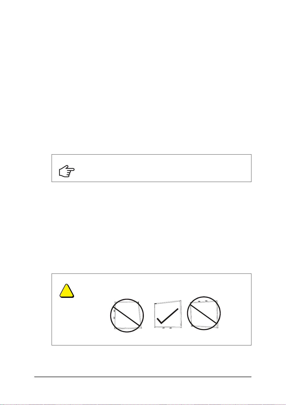
CAUTION
If you need to lean the interactive whiteboard against a wall before you mount
it, make sure it remains in an upright position, resting on the pen tray brackets,
which can sustain the weight of the interactive whiteboard.
Do not rest the interactive whiteboard on its side or on the top of the frame.
99-00737-25 Rev A0 Installing 600i Series Interactive Whiteboard Systems 7
Preparing the Installation Template
You must position and install the Unifi projector before you mount and adjust the position of the
interactive whiteboard. SMART provides the installation template to help you mount the
projector and the interactive whiteboard correctly.
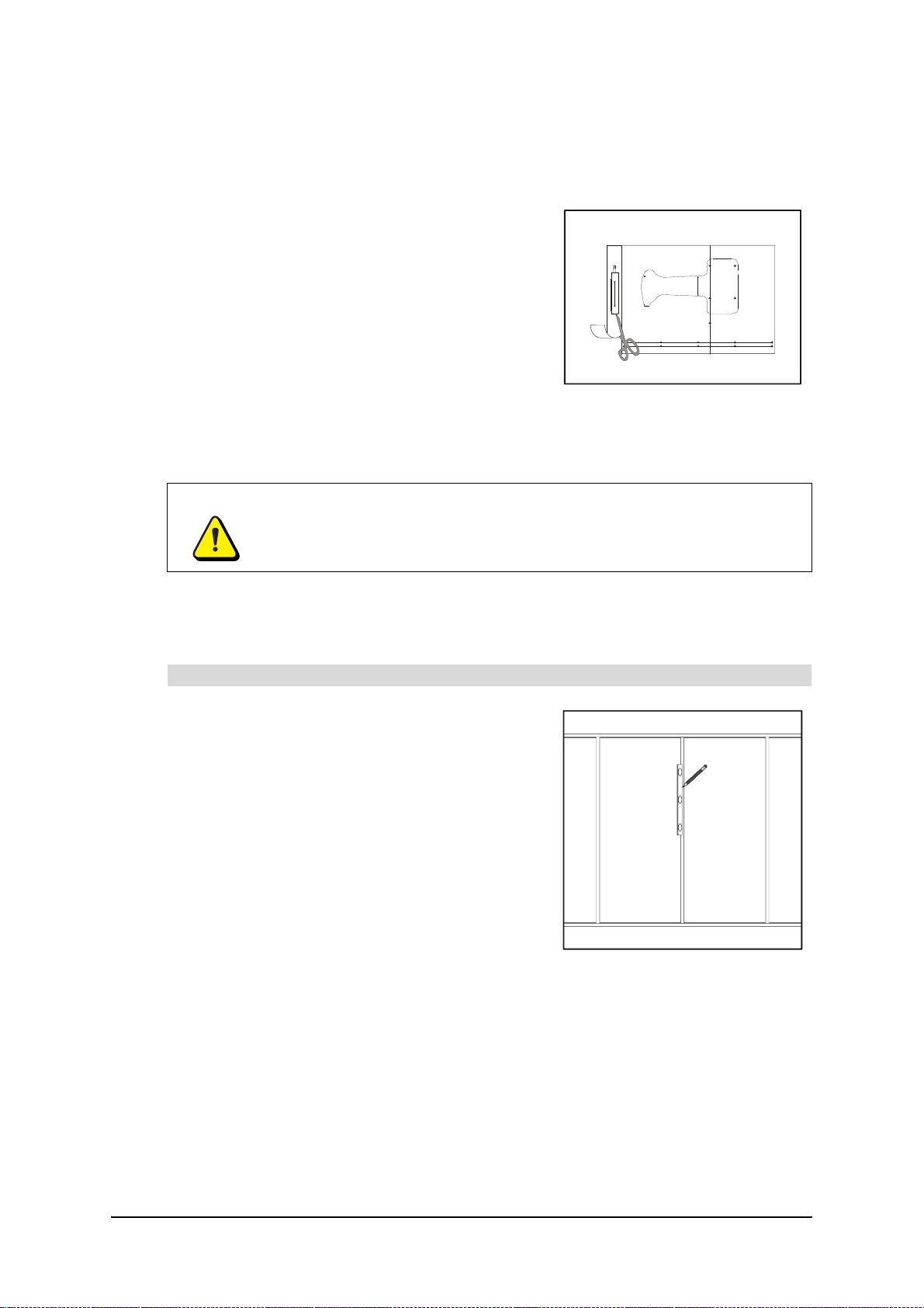
Before starting the installation, cut the extended
connection panel part from the included installation
template and reserve it for a later step. If you are
installing the projector close to the ceiling, cut along the
template’s top line.
The first procedure in the following section illustrates
the mounting of the 600i interactive whiteboard system
onto a framed wall surfaced with gypsum or drywall. If
you are mounting your 600i system on a concrete wall,
go to the To mount the SMART Board 600i projector
bracket on a concrete wall procedure page 10.
Installing the 600i Interactive Whiteboard System
WARNING
Two people are required to safely mount the 600i interactive whiteboard system
on a wall.
NOTE: To mount the Unifi projector safely on a framed wall, you must attach the mounting
plate to a stud. If the wall doesn’t have a stud in a suitable location, you can secure a sheet of
1/2 " (13 mm) or thicker plywood to the wall, and then mount the projector on it.
To mount the SMART Board 600i projector bracket on a framed wall
1. Locate a stud near the center of the area where
you want to mount the 600i interactive whiteboard
system using a stud finder.
2. Draw a vertical line on the wall marking the
centerline of the stud using a pencil and a
carpenter’s level.
8 Installing 600i Series Interactive Whiteboard Systems 99-00737-25 Rev A0

3. Position the installation template on the wall with
the three indicated holes centered on the stud.
4. Slide the template up or down the wall until it is at
the desired height as recommended by the line at
the bottom of the template using a measuring tape
or ruler. Use a carpenter’s level to ensure that the
template is level.
NOTE: Be sure to position the projector bracket at
least 5" (12.7 cm) from the ceiling to provide
adequate airflow around the projector.
Center
Holes on
Stud
IMPORTANT
When mounting the projector on a framed wall, you must attach the
mounting bracket to a stud to safely support the projector’s weight. If you
use drywall anchors only, the anchors or the drywall can fail, resulting in
product damage and possible personal injury.
5. Pin or tape the template to the wall.
6. Locate the row of marks on the template that
identify the location of the bracket mounting holes
for your model of interactive whiteboard. Mark the
wall at each anchor location using a pencil.
99-00737-25 Rev A0 Installing 600i Series Interactive Whiteboard Systems 9

7. Mark the six holes for the projector mounting plate
anchors and the security cable anchor, and then
remove the template from the wall.
8. For a wooden stud wall, drill a 1/8" (3 mm) pilot
hole at the center three marks, and then screw in
one of the included pan-head wood screws with a
washer into each of the top two holes in the center
column, leaving the heads about 1/4" (6 mm) from
the wall surface. Don’t screw in the security cable
screw at this time.
For a metal stud wall, drill 7/16" (11 mm) holes
through the drywall and the stud at each of the two
center marks and the security cable mark.
Drill 5/16" (8 mm) holes at the remaining three marks.
9. Insert the included drywall anchors into all of the
drilled holes, and screw them in until they are flush
with the drywall surface. Do not use a hammer to
insert the anchors.
Wood
Screws
Drywall Anchor
and Bolt
10. Screw the anchor bolts with washers into the
bracket anchors, leaving the heads about 1/4"
(6 mm) from the wall surface. Don’t screw in the
bolt for the security cable at this time.
11. Hang the projector bracket on the five screws and
anchor bolts, use a carpenter’s level to ensure that
the bracket is level, and then tighten the screws
and bolts securely.
To mount the SMART Board 600i projector bracket on a concrete wall
1. Draw a vertical line on the wall about 2" (5 cm) to
the right of the center of the interactive
whiteboard’s planned position using a pencil and a
carpenter’s level.
Center of
lnteractive
Whiteboard
10 Installing 600i Series Interactive Whiteboard Systems 99-00737-25 Rev A0

2. Position the installation template on the wall with
the three indicated holes centered on the line.
3. Slide the template up or down the wall until it is at
the desired height as recommended by the line at
the bottom of the template using a measuring tape
or ruler. Use a carpenter’s level to ensure that the
template is level.
NOTE: Position the projector bracket at least 5"
(12.7 cm) from the ceiling in order to ensure
adequate airflow around the projector.
4. Locate the row of marks on the template that
identify the location of the bracket mounting holes
for your model of interactive whiteboard. Use a
pencil to mark the wall at each anchor location.
Center
Holes on
Line
5. Mark the six holes for the projector mounting plate
anchors and the security cable anchor, and then
remove the template from the wall.
6. At each of the marks (including the security cable
mark) drill 5/16" (8 mm) holes into the concrete
wall.
7. Insert the included concrete anchors into all of the
drilled holes, pushing them in until the sleeve is
flush with the wall surface. Tighten the nuts to
secure the anchor in the wall, and then remove the
nuts.
Concrete
Anchor Bolt
99-00737-25 Rev A0 Installing 600i Series Interactive Whiteboard Systems 11

8. Place a washer on each bolt, and then replace the
nuts, leaving them about 1/4" (6 mm) from the wall
surface. Don’t screw in the bolt for the security
cable at this time.
9. Hang the projector bracket on the five anchor bolts,
use a carpenter’s level to ensure that the bracket is
level, and then tighten the nuts securely.
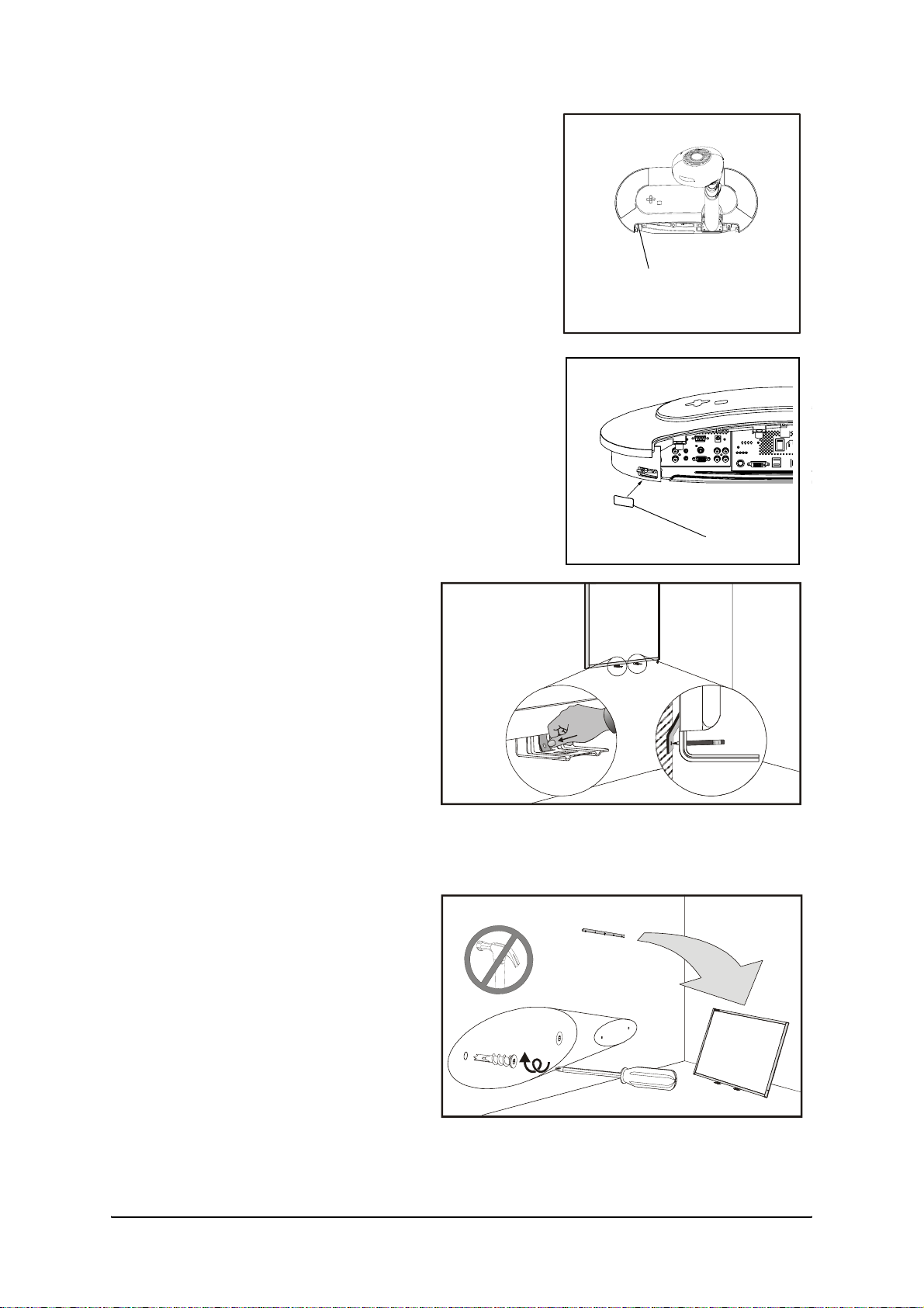
To mount the projector on the bracket
1. Remove the two screws from the lower corners of
the projector base using a Phillips No. 1
screwdriver, and then remove the connection panel
cover.
2. Mount the Unifi projector on the projector bracket,
ensuring that both hooks are fully engaged.
WARNING
Make sure that both mounting hooks are fully engaged before releasing the
projector. Failure to do so can result in product damage and personal
injury.
3. Tighten the locking screw through the access hole
located on the right side of the projector base using
a Phillips No. 2 screwdriver.
Cover Screw
Cover Screw
Projector Base
Mounting Hooks
Locking Screw
Access Hole
WARNING
The locking screw contributes to the structural integrity of the projector’s
mounting system. You must use it. It prevents the removal of the projector
from the mounting bracket. Make sure that the locking screw is fully
inserted and tightened. Failure to do so can result in image alignment
problems, product damage, personal injury or theft.
12 Installing 600i Series Interactive Whiteboard Systems 99-00737-25 Rev A0

4. Attach the security cable to the wall using the
included large washer and the remaining screw (for
a wooden stud) or anchor bolt (for a metal stud or
concrete wall).
Security Cable
WARNING
Make sure that the security cable is securely attached to the wall. If
excessive force placed on the boom causes the projector to break away
from the wall, the cable prevents the projector from falling and causing
injury.
To connect the extended connection panel and cables
1. Plug all the extended connection panel (ECP) cable connectors into their receptacles on
the projector base’s connection panel, as shown. Don’t mount the ECP at this time.
To ECP
2 × RCA
Audio
Jacks
To ECP
Mini
Stereo
Jack
To ECP
HD-DB15
Video
Connector
To ECP
Reset
Button
To ECP
RCA
Video
Jack
To EC P
S-video
Connector
To E C P
USB A
Storage
Device
Connector
USB Cable
to USB B
SC9
Module
Connector
To ECP
USB B
Computer
Connector
Power
Cable to
Outlet
2. Connect the Type A connector of the 16' (5 m) USB cable (included with the interactive
whiteboard) to the unused Type A USB receptacle on the projector’s connection panel.
IMPORTANT
Do not use the shorter 6' (1.8 m) USB cable included with your projector to
connect the projector to the interactive whiteboard. Reserve this cable to
connect the projector’s extended connection panel to your computer.
3. Connect the power cable to the power connector on the connection panel, and then turn
on the master power switch. Don’t connect the cable to a power source at this time.
99-00737-25 Rev A0 Installing 600i Series Interactive Whiteboard Systems 13

To prepare for mounting the interactive whiteboard
1. NOTE: If you’re upgrading an existing 600 series
interactive whiteboard to a 600i system, go to step
3 below (see page 25).
For a framed wall, screw in one of the included selftapping wall anchors at each mark. Do not use a
hammer to tap these anchors into the wall.
For a concrete wall, drill holes at the marks, and
insert concrete anchors (not included) into the
holes.
2. Attach the wall mount bracket using the screws
included with the anchors.
4
3. Temporarily hang the interactive whiteboard on the
wall mount bracket.
To mount the interactive whiteboard and align the image
IMPORTANT
1. Plug the projector’s power cable into a wall outlet,
and then use the remote control to turn on the
projector.
2. Unlatch the projector boom clamp closest to the
base, extend the first section completely, and then
latch the clamp.
Leave a 3/8" (1.0 cm) margin between the projected image and each outer
edge of the screen’s surface. Don’t extend the image to the edge of the
screen’s surface.
Boom Clamps Focus Knob
3. To adjust the image size, unlatch the other clamp
and extend or contract the last section of the
boom.
4. Adjust the projector focus using the knob on the
side of the projector head before latching the boom
clamp, as focusing the image changes the size
slightly.
5. Slide the interactive whiteboard sideways on its
bracket to align it with the projected image.
14 Installing 600i Series Interactive Whiteboard Systems 99-00737-25 Rev A0
6. If the image isn’t level, adjust the projector leveling
screws to the left of the projector’s connection
panel.
7. Repeat steps 3 through 6 until the system is
properly aligned.
NOTES
– If the image is wider at the top or the bottom,
see page 20 for keystone alignment
instructions.
– Do not adjust the projector alignment screws
inside the projector head.
8. Install the leveling screw cover in the lower-left of
the projector base.
Leveling Screws
leveling
Screw
Cover
9. Locate the two L-shaped metal
brackets below the interactive
whiteboard’s bottom frame, and
push the metal tab in the center of
each bracket back until it contacts
the wall, and then mark the
location of the mounting holes.
NOTE: If you are upgrading an
existing 600 series interactive
whiteboard to a 600i system, (see
page 25) your pencil marks
probably won’t line up with the
existing mounting holes. You
must install new anchors (not
included) to align the interactive
whiteboard correctly.
10. Remove the interactive
whiteboard from the wall.
11. If you’re mounting the system on
a framed wall, screw in one of the
included self-tapping wall anchors
at each mark.
If you’re mounting the system on
a concrete wall, drill holes at the
marks, and insert concrete
anchors (not included) into the
holes.
6
99-00737-25 Rev A0 Installing 600i Series Interactive Whiteboard Systems 15

12. Place the included control module cable into the
track on the back of the interactive whiteboard,
leaving the ends hanging near each end of the
bottom frame.
13. Put the interactive whiteboard back on the wall
mount bracket.
14. Screw the L-shaped metal brackets to the wall
anchors using the screws included with the
anchors.
NOTE: If you want to lock your interactive
whiteboard with a security cable, see To lock the
pen tray to the interactive whiteboard (page 24)
before you secure the brackets.
To install the control module
1. From the bottom of the pen tray, bend the expansion
slot cover’s two plastic tabs toward the front of the
pen tray, and then push it up to remove it.
2. Place the 600i control module into the pen tray’s
expansion slot and gently push down until it snaps
into place.
7
To install the pen tray
1. Position the pen tray in line with the two L-shaped
metal brackets, and slide it toward the wall until it is
seated firmly.
16 Installing 600i Series Interactive Whiteboard Systems 99-00737-25 Rev A0
8

2. Route the modular I²C cable from the interactive
whiteboard’s SC9 controller module (under the
9
lower-right end of the pen tray) and insert it into
connector number 1 on the bottom of the pen tray.
Press the cable into the strain relief channel on the
bottom of the tray to protect the modular cable’s
RJ11 connector from damage if the pen tray is
removed without first disconnecting the cable.
Connector 1
3. Insert the control module cable (see step 12 on page 16) into connectors 2 and 3 on the
bottom of the pen tray, and then press the cable into the strain-relief channels.
Connector 3
Control Module Cable
Connector 2
4. Move all the pen tray cables out of sight behind the interactive whiteboard.
To install the wire cover
In the accessory kit included with your 600i interactive whiteboard system are two sizes of wire
cover; use the narrower cover with 660i systems, and the wider cover with 680i systems.
1. Remove the backing from the adhesive on the
included foam strip, and then press the foam strip
onto the lower edge of the wire cover.
Foam Strip
2. Attach the wire cover to the lower cover using the
two included metal clips as shown.
Wire Cover
Metal
Clips
Wire Cover
Lower Cover
99-00737-25 Rev A0 Installing 600i Series Interactive Whiteboard Systems 17

3. Install the connection panel cover with the attached
wire cover onto the base of the Unifi projector, and
then replace the screws at each end of the cover
(see step 1 on page 12).
NOTE: Verify that the power switch is in the ON
position before you install the cover.
To complete the installation
1. Identify a suitable location for the extended
connection panel near the bottom left corner of the
interactive whiteboard. Be sure that the connectors
are easily accessible.
NOTE: The drawing to the right shows only one of
several possible locations for the extended
connection panel.
2. Using the extended connection panel part of the
installation template (page 8), mark the locations of
the mounting anchors.
3. If you’re mounting the connection panel on a
framed wall, push in one of the included wall
anchors at each mark.
If you’re mounting the connection panel on a
concrete wall, drill holes at the marks, and then
insert concrete anchors (not included) into the
holes.
Connection
Panel Cover
Wire Cover
4. Screw in the anchor screws or bolts leaving the
heads about 1/8" (3 mm) from the wall surface.
5. Position the keyholes on the back of the extended
connection panel over the anchor screw heads and
slide the panel to lock it into position. You may have
to adjust the screw depth slightly for a secure fit.
Move the cable neatly out of sight behind the
interactive whiteboard.
18 Installing 600i Series Interactive Whiteboard Systems 99-00737-25 Rev A0

6. Connect the USB cable from the projector base to
the captive USB cable’s connector at the lowerright corner of the interactive whiteboard. Hide the
excess cable behind the interactive whiteboard.
7. Place the four pens and the eraser into their
respective recesses in the pen tray.
11
99-00737-25 Rev A0 Installing 600i Series Interactive Whiteboard Systems 19

Adjusting Keystone Alignment Errors
During the manufacturing process, SMART precisely aligns the Unifi 35 projector. When you
install the system on a flat wall using the procedures starting on page 8, you don’t need to
perform keystone adjustment. If you’ve followed the installation procedures carefully and the
projected image isn’t aligned, your projector may have been damaged during shipping.
Contact your SMART service representative.
When you use standard projectors, keystone errors occur when the projected image isn’t
perpendicular to the screen. The image appears wider at the bottom when the distance from
the projector lens to the bottom of the screen is greater than the distance to the top of the
screen. The image appears wider at the top when the distance from the projector lens to the
top of the screen is greater than the distance to the bottom of the screen.
Bottom of Interactive Whiteboard
is Too Far from the Projector Lens
Top of Interactive Whiteboard
is Too Far from the Projector Lens
Keystone errors can occur when you mount the Unifi™ 35 short-throw, high-offset projector
and the interactive whiteboard used in SMART Board 600i interactive whiteboard systems on
an uneven surface, or on a wall that has obstructions such as a whiteboard or aluminum rails.
About Correcting Keystone Errors
When possible, position the interactive whiteboard so that it aligns with the projected image.
This eliminates keystone errors. If your installation prevents you from moving the interactive
whiteboard, you may be able to adjust the Unifi 35 projector boom alignment to correct image
distortion.
NOTE: Do not adjust the projector boom alignment unless necessary.
• If you move the projector to a new location you must return its alignment to factory
settings.
• If your projector requires service, you must adjust the replacement projector.
WARNING
It takes two people to safely lift the interactive whiteboard on or off its wall
mount bracket.
NOTE: Do not attempt the following procedures unless you are familiar with the installation
procedures starting on page 8.
20 Installing 600i Series Interactive Whiteboard Systems 99-00737-25 Rev A0

Aligning the Interactive Whiteboard
To prepare to align the interactive whiteboard
1. If your 600i system is fully installed, remove the pen
tray from the interactive whiteboard. See page 16.
2. Remove the screws from the pen tray brackets, and
put them aside.
The bottom of the interactive whiteboard is free from
the wall. Don’t lift the interactive whiteboard off the
wall mount bracket.
3. Connect the projector’s power cable to a wall outlet,
and then turn on the projector using the remote
control.
X
To adjust the projected image if it is wider at the bottom
1. While holding the interactive whiteboard against the wall, measure the space between the
bottom frame and the wall.
2. Gently pull the bottom of the interactive whiteboard away from the wall until the sides of
the image are parallel, and then measure how far you moved the bottom of the interactive
whiteboard.
NOTE: You may have to adjust the projector boom length and focus slightly during this
step.
3. Make two spacers of the correct thickness to put behind the bottom corners of the
interactive whiteboard.
4. Lift the interactive whiteboard from the wall mount bracket, and then place it face down on
a flat surface.
5. Tape one of the spacers to the back of the SC9 controller module, and the other to the
round pad on the back of the left frame.
6. Return the interactive whiteboard to the wall mount bracket.
7. Replace the two pen tray bracket screws, and then replace the pen tray.
To adjust the projected image if it is wider at the top
1. While holding the interactive whiteboard against the wall, measure the space between the
top frame and the wall.
2. Lift the interactive whiteboard off its mounting bracket, and then hold the interactive
whiteboard against the wall at the same height as when it was mounted.
3. Pull the top of the interactive whiteboard away from the wall until the sides of the image
are parallel, and then measure how far you moved the top of the interactive whiteboard.
NOTE: You may have to adjust the projector boom and focus slightly during this step.
4. Put the interactive whiteboard aside.
5. Make a spacer of the correct thickness to fit behind the wall mount bracket.
6. Remove the wall mount bracket screws using a Phillips® No. 2 screwdriver, and then
remove the bracket.
7. Place the spacer behind the wall mount bracket, and then replace the bracket.
8. Return the interactive whiteboard to the wall mount bracket.
9. Replace the two pen tray bracket screws, and then replace the pen tray.
99-00737-25 Rev A0 Installing 600i Series Interactive Whiteboard Systems 21

Aligning the Unifi 35 Projector Boom
CAUTION
Read the following procedure carefully before adjusting the boom alignment.
Improper adjustment can damage the projector severely, potentially voiding the
projector’s warranty.
To adjust the Unifi 35 projector boom alignment
1. Remove the screws from the connection panel
cover using a Phillips No. 1 screwdriver, and then
remove the connection panel cover and the wire
cover from the base of the projector.
Screw
Connection
Panel Cover
2. Completely remove the two locking screws from the projector boom mounting plate and
set them aside.
Alignment Adjustment
Screws
Screw
Wire Cover
Plate
IMPORTANT
Projector Boom
Mounting Plate
Locking Screws
(shown removed)
You can damage the projector boom mounting plate or the projector base
Projector BoomProjector Base
plate if you do not remove the locking screws before adjusting the boom
alignment.
3. Adjust both adjustment screws at the same time, and don’t turn the screws more than a
quarter turn (90°) at a time.
– If the image is wider at the bottom, turn the adjustment screws counter-clockwise to
lower the boom.
– If the image is wider at the top, turn the adjustment screws clockwise to raise the
boom.
NOTE: You may have to adjust the projector boom length and focus slightly during this
step.
22 Installing 600i Series Interactive Whiteboard Systems 99-00737-25 Rev A0

4. After adjusting the screws, check the projected image for keystone error.
5. Repeat steps 3 and 4 until the keystone error is eliminated.
NOTE: When you raise the boom, do not allow more than 0.5" (13 mm) space between the
bottom of the mounting plate and the projector base plate. If you can’t eliminate the
keystone error, contact your SMART technical support representative.
Projector
Boom
Projector Base
Plate
Alignment
Adjustment
Screws
Locking
Screws
Maximum 0.5"
(13 mm) Space
6. Replace the locking screws, and then tighten them to prevent the adjustments from
changing.
7. Replace the connection panel cover and wire cover onto the base of the projector.
99-00737-25 Rev A0 Installing 600i Series Interactive Whiteboard Systems 23

Securing the Pen Tray and Interactive Whiteboard
Because the pen tray that comes with your SMART Board interactive whiteboard is
detachable, you may want to safeguard it—and the interactive whiteboard at the same time—
by anchoring it with a security cable.
IMPORTANT
Securing the pen tray can provide theft deterrence for the interactive
whiteboard as well. The screws that secure the interactive whiteboard to the
wall are located directly behind the pen tray. The pen tray must be removed
before you can remove the interactive whiteboard. In effect, when you secure
the pen tray, you’re also securing the interactive whiteboard, if the security
cable is tight.
To lock the pen tray to the interactive whiteboard
Underneath the pen tray, you’ll find a lock slot that accommodates a security cable, such as a
Kensington® lock.
Lock Slot
Loop the security cable behind the pen tray brackets before you screw them to the wall (as
shown in step 1 on page 16) and then thread the lock end of the cable through the loop end of
the cable. Verify that the cable is tight enough to prevent you from removing the pen tray while
the lock is in place. Install the pen tray. Insert the prong-end of the security cable into the lock
slot and then complete the pen tray installation.
To secure the pen tray to the pen tray brackets
Because you can remove the pen tray without tools, you may want to securely attach it to its
brackets. To do this, you can insert two No. 8/M4 screws (not included) into the holes shown in
the illustration below. Note that older pen trays do not have this feature.
Screw Location
24 Installing 600i Series Interactive Whiteboard Systems 99-00737-25 Rev A0

Upgrading a 600 Series Interactive Whiteboard to a 600i System
Read this section carefully before upgrading your 600 series interactive whiteboard to a 600i
system. Use this checklist to determine whether you can upgrade your 600 series interactive
whiteboard to a 600i interactive whiteboard system.
Upgrade Checklist
Item Question Yes No
1 Is your interactive whiteboard a model 660 or 680?
You can’t use the Unifi projector with model 640 or 690
interactive whiteboards.
2 Measured from the floor to the top of the interactive whiteboard’s
frame, is the top currently 81" (206 cm) or higher above the floor?
If the floor to top frame measurement is less than 81" (206 cm),
then you may be unable to mount Unifi projector at a safe
height, or meet local regulations.
3 Measured from the top of the frame and the ceiling, is there 16 3/4"
(42.5 cm) or more space between the top frame of model 660
interactive whiteboard, or 17 1/4" (42 cm) or more space for the
model 680 interactive whiteboard?
If the clearance is too small, the Unifi projector won’t receive
adequate cooling airflow.
4 If your interactive whiteboard is mounted on a framed wall, can you
slide it sideways, up to 10" (25 cm), if required?
Because the Unifi projector mounting plate must be attached to
a stud that can safely support the projector’s weight, you may
not be able to center the projector over the interactive
whiteboard’s current position. You must be able to move the
interactive whiteboard sideways to align it with the projector’s
image.
5 If your interactive whiteboard is mounted on a concrete wall, can
you slide it sideways, up to 3" (7.5 cm), if required?
You must be able to adjust the interactive whiteboard sideways
to align it with the projector’s image.
6 Are you using a USB cable to connect the computer to the
interactive whiteboard?
You must use a USB cable to connect a computer to the 600i
system. You can’t use the serial or wireless Bluetooth®
connection options.
If you checked No for any of the previous questions, you may not be able to upgrade your
existing interactive whiteboard to a 600i system in its current location.
99-00737-25 Rev A0 Installing 600i Series Interactive Whiteboard Systems 25

Preparing for the Upgrade
Before you can install the Unifi 35 projector above your 600 series interactive whiteboard, you
must remove the interactive whiteboard from the wall.
To remove the existing interactive whiteboard
1. Remove the pens and the eraser from the pen tray.
2. Disconnect the USB cable from the captive USB
cable’s connector at the lower right corner of the
interactive whiteboard.
11
3. Pull the modular I²C cable out of the strain-relief
channel on the bottom of the pen tray, and then
9
disconnect it from connector 1.
4. If you secured the pen tray to its brackets using two
screws (page 24), remove these screws.
5. If you secured the pen tray using a Kensington lock
or similar device, unlock and remove the lock.
Connector 1
6. Reach underneath the pen tray, and then pull down
on the two large plastic clips on the bottom of the
pen tray. The ends of these clips project
downwards slightly, so they’re easy to find.
The Pen Tray Viewed from Below
Plastic Clips
7. Continue to apply downward pressure to the clips and gently slide the pen tray toward you
until it’s free of the two L-shaped metal brackets, and then set the pen tray aside.
8. Remove the screws from both pen tray brackets,
and, with the assistance of another person, lift the
interactive whiteboard from the wall bracket and set
it aside.
NOTE: When you reinstall the interactive
whiteboard, you will probably have to mount it to the
left or right of its current position. You will require
replacement anchors and screws.
26 Installing 600i Series Interactive Whiteboard Systems 99-00737-25 Rev A0

To position the projector above the interactive whiteboard — framed wall
1. Using a stud finder, locate the stud closest to the
center of the 600 series interactive whiteboard wall
bracket.
2. Using a pencil and a carpenter’s level, draw a
vertical line on the wall, marking the stud’s
centerline.
3. Position the installation template on the wall with
the three holes indicated in the diagram centered
on the stud.
4. Slide the template up or down the wall until the row
of marks for your size of interactive whiteboard
aligns with the row of screws in the mounting
bracket. Use a carpenter’s level to ensure that the
template is level. Tape the template to the wall.
NOTES
– The markings on the template probably won’t
line up with the mounting bracket screws.
Mounting
Bracket
Align With
Bracket
Holes
Center
Holes on
Stud
– Be sure to position the projector bracket at
least 5" (12.7 cm) from the ceiling in order to
provide adequate airflow around the projector.
WARNING
When mounting the projector on a framed wall, you must attach the
mounting bracket to a stud that can support the projector’s weight. If you
use drywall anchors only, the anchors or the drywall may not be able to
support the projector, resulting in product damage and possible personal
injury.
5. Mark the six holes for the projector mounting plate
anchors and the security cable anchor, and then
remove the template from the wall.
6. For a wooden stud wall, drill a 1/8" (3 mm) pilot
hole at the three center marks, and then screw in
one of the included pan-head wood screws with a
washer into each of the top two holes, leaving the
heads about 1/4" (6 mm) from the wall surface.
Don’t screw in the security cable screw at this time.
For a metal stud wall, drill 7/16" (11 mm) holes
through the drywall and the stud at each of the two
center marks and the security cable mark.
7. Drill 5/16" (8 mm) holes at the remaining three
marks.
99-00737-25 Rev A0 Installing 600i Series Interactive Whiteboard Systems 27

8. Insert the anchors (included) into all of the drilled
holes, and then screw them in until they are flush
with the drywall surface. See page 10 for an
illustration of the anchor. Do not use a hammer to
insert the anchors.
9. Screw the anchor bolts with washers into the
bracket anchors, leaving the heads about 1/4"
(6 mm) from the wall surface. Don’t screw in the
bolt for the security cable at this time.
10. Hang the projector bracket on the five screws and
anchor bolts, use a carpenter’s level to ensure that
the bracket is level, and then tighten the screws
and bolts securely.
11. Go to To mount the projector on the bracket on page 12 to complete the upgrade.
To position the projector above the interactive whiteboard — concrete wall
1. Using a pencil and a carpenter’s level, draw a
vertical line on the wall about 2" (5 cm) to the right
of the center of the interactive whiteboard’s wall
bracket.
2. Position the installation template on the wall with
the three holes indicated in the diagram centered
on the vertical line.
3. Slide the template up or down the wall until the row
of marks for your interactive whiteboard model
aligns with the row of screws in the mounting
bracket. Use a carpenter’s level to ensure that the
template is level. Tape the template to the wall.
NOTES
– The markings on the template may not align
with the mounting bracket screws.
– Be sure to position the projector bracket at
least 5" (12.7 cm) from the ceiling, in order to
provide adequate airflow around the projector.
Wall Mount
Bracket
Centerline
of Bracket
Holes
Align With
Bracket
Holes
Center of
Wall Bracket
Center
Holes on
Line
28 Installing 600i Series Interactive Whiteboard Systems 99-00737-25 Rev A0

4. Mark the six holes for the projector mounting plate
anchors and the security cable anchor, and then
remove the template from the wall.
5. At each of the marks (including the security cable
mark) drill 5/16" (8 mm) holes into the concrete
wall.
6. Insert the included concrete anchors into all of the
drilled holes, pushing them in until the sleeve is
flush with the wall surface. Tighten the nuts to
secure the anchor in the wall, and then remove the
nuts. See page 11 for an illustration of the anchor.
7. Place a washer on each bolt, and then replace the
nuts, leaving them about 1/4" (6 mm) from the wall
surface. Don’t screw in the bolt for the security
cable at this time.
8. Hang the projector bracket on the five screws and
anchor bolts, use a carpenter’s level to ensure that
the bracket is level, and then tighten the nuts
securely.
9. Go to To mount the projector on the bracket on
page 12 to complete the upgrade.
99-00737-25 Rev A0 Installing 600i Series Interactive Whiteboard Systems 29

Updating 600i System Firmware
The 600i interactive whiteboard system has firmware in both the Unifi projector and the 600
series interactive whiteboard’s SC9 controller module.
Updating the Unifi Projector Firmware
To determine your Unifi 35 projector’s firmware version using the Unifi on-screen display, press
Settings > System Information. The version is located to the right of SMART FW VER.
To take advantage of the latest firmware enhancements for your Unifi 35 projector, check for
updates at www.smarttech.com/600ifirmware. You can download a wizard that leads you
through the steps to install the update.
NOTE: You can use software developed by SMART Technologies on SMART products only.
The use of software developed by SMART Technologies is subject to the terms and conditions
of the Software End User License Agreement.
Updating the Interactive Whiteboard’s SC9 Firmware
Early versions of SC9 controller firmware don’t work with the Unifi projector. You must update
the SC9 firmware to version 4.1.2.0 or later before it will work with 600i systems.
To see your interactive whiteboard’s SC9 firmware version using the Unifi on-screen display,
press Settings > System Information, and read the value to the right of SC9 FW VER.
When you install SMART Board software, the installation program copies SC9 firmware files
onto your hard drive. If you don’t have SMART Board software installed, install the SC9
firmware files using the CD included with 600i systems.
If the files on your computer are earlier than version 4.1.2.0, or if you want to see if an update
is available, visit www.smarttech.com/support/software/index.asp.
To update the SC9 firmware
1. Disconnect the USB cable from the interactive
whiteboard’s SC9 controller to the Unifi projector.
2. Connect the SC9 controller directly to your computer
with a standard USB cable.
3. On Windows based computers, browse to the
SMART Board Software folder, and then double-click
the SB-W.X.Y.Z Flash.exe file (W.X.Y.Z represents
the version number of the firmware).
On Mac computers, click Go > Applications >
SMART Board Software, and then double-click
SC9-W_X_Y_ZFlash (W_X_Y_Z represents the
version number of the firmware).
The SMART Firmware Upgrade wizard appears.
4. Click Next to start a search for connected interactive whiteboards.
11
5. When the wizard locates your connected interactive whiteboard, click Next to continue.
The wizard displays the current firmware version and the latest update version available
on the computer.
If the update version is earlier than or the same as the current version, or if the wizard is
unable to locate your interactive whiteboard because it isn't correctly connected to the
computer, click Finish or Cancel to exit the wizard.
30 Installing 600i Series Interactive Whiteboard Systems 99-00737-25 Rev A0

6. Select the Yes option, and then click Next to begin the SC9 firmware update.
The Ready light flashes amber during the update.
7. When the update is complete, click Next, and then click Finish.
The interactive whiteboard restarts automatically, and the Ready light is solid green.
8. Reconnect the USB cable between the interactive whiteboard’s SC9 controller and the
Unifi projector.
NOTE: If the firmware update is unsuccessful, repeat the procedure. If the update is
unsuccessful after a second attempt, contact your support representative.
99-00737-25 Rev A0 Installing 600i Series Interactive Whiteboard Systems 31

32 Installing 600i Series Interactive Whiteboard Systems 99-00737-25 Rev A0

Connecting the 600i System to a Computer
In this Chapter
Refer to these topics for information about connecting the 600i system to a computer and
adjusting the orientation of the 600i system.
• Operating Safety and Precautions (this page)
• Connecting with a USB Cable (page 34)
To connect to the extended connection panel (ECP)
To install the USB driver (Windows only)
To install SMART Board software
• Connecting With a Serial (RS-232) Cable (page 36)
– Connecting a Resident Serial Computer (page 36)
To configure the serial, video and audio inputs for the resident computer
To disable Room Control mode using the Unifi software on-screen menus
To connect the resident computer
• Connecting a Guest Laptop (page 39)
– Using Multiple SMART Products (page 39)
• Orienting the SMART Board 600i Series Interactive Whiteboard (page 40)
– Default Manufacturing Orientation (page 40)
– Orienting with the Unifi Projector Interface (page 40)
– Orienting with a Computer (page 40)
To orient the interactive whiteboard
To set the orientation precision
• Configuring the Room Control Feature (page 42)
To enable room control using Unifi software’s on-screen menu
To configure your serial interface settings
To verify that the serial interface is in Room Control mode
• Command Summary (page 43)
– SET Commands (page 43)
– Power Control Commands (page 43)
– Configuration Commands (page 43)
– Query Commands (page 44)
• Finding More Information (page 44)
Operating Safety and Precautions
IMPORTANT
To ensure safe operation and to avoid damage to the SMART Board 600i
series interactive whiteboard system, connect the USB connector of the Unifi
35 projector only to a computer that has a USB compliant interface and that
bears the USB logo. In addition, the USB source computer must be compliant
with CSA/UL/EN 60950 and bear the CE mark and CSA and/or UL mark(s) for
CSA/UL 60950.
99-00737-25 Rev A0 Connecting the 600i System to a Computer 33

Connecting with a USB Cable
You can connect all 600i interactive whiteboards systems to a computer using the USB
interface on the extended connection panel. SMART provides a 6' (1.8 m) USB cable, or you
can purchase cables locally. The systems have a high-power USB 2.0 full-speed peripheral
interface that runs at speeds of up to 12 Mbps. The units work with USB 2.0- and USB 1.1compliant USB interfaces.
To connect to the extended connection panel (ECP)
1. Connect the included 6' (1.8 m) USB cable to the USB
Type B receptacle on the ECP.
2. Plug the other end of the USB cable into a USB
receptacle on your computer.
IMPORTANT
3. Connect the included 6' (1.8 m) VGA-HD cable to the ECP’s DB15 VGA connector.
4. Plug the other end of the VGA-HD cable into a DB-15 VGA receptacle on your computer.
5. If you use the audio output from your computer, connect the included 6' (1.8 m) 3.5 mm
stereo phone cable to the ECP’s 3.5 mm phone jack.
6. Plug the other end of the audio cable into a 3.5 mm phone jack on your computer.
If you are using a Mac computer (with the OS X operating system), or if you already have
the appropriate USB driver installed on your computer, you can install SMART Board
software.
To install the USB driver (Windows only)
The computer sees the 600i system as a USB Human Interface Device (HID). If an appropriate
driver isn’t installed on the computer, a Found New Hardware wizard helps you locate a driver.
1. Click the Next button to direct the wizard to search for an appropriate driver.
2. Click Next again to make the Windows operating system search the driver database on
the computer’s hard drive for an appropriate driver.
NOTE: If the Windows operating system can’t find a driver, insert the Windows 2000/XP
CD in your CD drive and install a USB HID driver. USB HID is a subclass of USB devices,
and the drivers are not always included in a default installation. Computers must have
these drivers before a USB connection to the 600i system will work correctly.
Do not use a USB cable longer than 6' 5" (2 m) to connect your computer to
the extended connection panel. If you use a longer cable, its length, when
combined with that of the extended connection panel cable, exceeds USB
specifications, resulting in communication failure.
3. Click the Finish button after the driver search and installation is complete.
NOTE: If you have a Mac computer or a Windows computer with a USB driver installed, you
can now connect the 600i in HID (Mouse) mode. USB drivers are not currently available for
Linux computers, so you must install SMART Board software before you can connect to the
600i.
34 Connecting the 600i System to a Computer 99-00737-25 Rev A0

To install SMART Board software
1. Put the SMART Board software CD, version 9.5 or later, in your CD drive and follow the
on-screen instructions.
NOTE: If SMART Board software is already installed on your computer, you can use this
opportunity to upgrade the software to ensure compatibility. SMART Board software
upgrades are available at www.smarttech.com/support/software/index.asp.You can’t use
SMART Board software versions earlier than 9.5 with the 600i system.
2. If the SMART Board tools do not open automatically, select Start > Programs > SMART
Board Software > SMART Board Tools, or double-click the SMART Board Tools icon
on your desktop.
You can now pick up a pen tray pen and write on the interactive screen in digital ink, and
capture your notes into any Ink Aware application. Refer to the SMART Board software online
Help for a list of Ink Aware applications.
USB Extender Cables and Hubs
The 16' (5 m) USB cable included with the interactive whiteboard is within the limit defined by
the USB 2.0 standard for maximum length. If the included USB cable isn’t long enough, you
can use active USB extender cables, USB extenders or hubs.
When used with a 600i series interactive whiteboard system,
the SMART active USB extension cable shown here (Part No.
USB-XT) extends standard USB cables by 16' (5 m). You can
connect up to three active USB extenders to increase the total
cable length to about 64' (20 m). Note that passive USB
extension cables are not supported. Don’t use cables longer
than 6' (1.8 m) to connect these extenders to the extended
connection panel (ECP).
Alternately, USB extenders that use Cat 5 cables can extend
the range to approximately 325' (100 m), at a much higher
cost. The more economical SMART Cat 5 to USB extender
(Part No. CAT5-XT) shown here can extend the USB
connection up to 120' (36.6 m) using an RJ45 Cat 5 cable.
NOTE: Two 6' (1.8 m) USB cables are included with the Cat 5
extenders, and you must use them to connect the computer
and the interactive whiteboard. Don’t use cables longer than 6'
(1.8 m), and don’t connect these extenders through the
extended connection panel used with 600i systems. Connect
them directly to the Unifi projector base.
You can also use USB hubs with interactive whiteboards. If you also pass streaming audio
through the USB hub, ensure that the computer’s USB drivers are up-to-date, or the interactive
whiteboard’s performance might become choppy, intermittent or otherwise unacceptable.
NOTES
• Some computers use internal active hubs to provide more USB receptacles. A computer’s
operating system may interpret these internal hubs as external devices, which limits the
number of USB extenders that you can use.
• Cables and connectors must meet the specifications of the extenders and hubs.
Impedance mismatches and poor connections can cause signal degradation and
performance problems with the interactive whiteboard.
• USB extenders and hubs must be USB 1.1 or USB 2.0 compliant.
99-00737-25 Rev A0 Connecting the 600i System to a Computer 35

Connecting With a Serial (RS-232) Cable
You can connect a computer to the Unifi 35 projector’s serial (RS-232) interface. If you connect
the resident computer to the Unifi 35 projector’s RS-232 interface, you can also connect a
guest computer to the USB interface, and you can switch between the computers using the
Unifi on-screen menus.
NOTE: Your Unifi 35 projector must be running firmware version 1.2.13 or later to enable its
RS-232 interface. See (page 30).
Connecting a Resident Serial Computer
To serially connect a computer to the SMART Board 600i interactive whiteboard system you
must:
• configure the Unifi 35 projector’s serial, video and audio inputs for the resident computer
connections using the Unifi software on-screen menus.
• disable Room Control mode using the Unifi software on-screen menus.
• connect your computer’s serial, video and audio outputs to the Unifi 35 projector.
To configure the serial, video and audio inputs for the resident computer
NOTE: You must use either the DVI-A or the DVI-D video input with the Unifi 35 projector’s
serial connection.
1. Turn on the SMART Board 600i interactive whiteboard system.
The Unifi software splash screen appears.
2. Select any input, or select ScratchPad.
The Unifi software menu appears in the lower-left of the touch screen.
3. Press Settings.
4. Press Configure inputs.
The Configure Inputs dialog box appears, displaying the current configuration of the
projector’s inputs.
5. Select the check box on the left of the DVI-A or the DVI-D input to enable the input.
6. Select the Serial option on the same row. You can select the Serial option for one input
only.
The Properties column displays the input names as they appear in the Unifi software onscreen menus. Typically, the USB computer input is labeled Computer 1 and the serial
computer input is labeled Computer 2.
7. Press Computer 2 in the Properties column.
The Audio Properties dialog box appears.
8. Select the audio input that you want to use with the serial computer connection.
NOTE: If you select an audio input that is used with another input, you can use a “Y”
adapter cable to connect both inputs.
9. Press Close in all dialog boxes to save your changes.
36 Connecting the 600i System to a Computer 99-00737-25 Rev A0

To disable Room Control mode using the Unifi software on-screen menus
You must disable the Unifi 35 projector’s Room Control mode to use its RS-232 interface to
communicate with your computer.
1. Turn on the SMART Board 600i interactive whiteboard system.
The Unifi software splash screen appears.
2. Select any input source from the Unifi on-screen menu.
3. Press Settings.
4. Press Advanced Settings.
5. Press the wrench icon.
The Setup window appears.
6. Press Room Control Mode.
7. Use the on-screen navigation buttons to select Disable, and then press Enter.
8. Press Close in all dialog boxes to save your changes.
To connect the resident computer
You must install SMART Board software on the resident computer to communicate serially with
the Unifi 35 projector. SMART Board software is available at www.smarttech.com/support/
software/index.asp.
NOTE: You only have to perform this procedure the first time you connect your resident
computer. Unifi software and SMART Board software save the settings so that you can simply
start SMART Board software the next time you work with the system, and then select the
computer input from the Unifi software menu.
1. Connect the female connector of a straight-through DB9M-to-DB9F RS-232 cable to your
computer’s serial connector.
If your computer doesn’t have a serial (RS-232) interface, you can use a USB-to-serial
adapter to connect the computer’s USB port to the Unifi 35 projector’s serial connector.
See Serial Interface Settings on the next page.
2. Connect the male connector of the cable to the Unifi 35 projector’s DB9 connector.
NOTE: Unifi 35 projectors manufactured before February 2007 have a male DB9
connector. Therefore, you need a straight-through DB9F-to-DB9F RS-232 cable to
connect these projectors to a computer.
3. Connect video and audio cables from the computer to the Unifi 35 projector base
connection panel connectors.
– If your computer has a VGA (DB15-HD) analog video output, use the 10' (3 m) DVI-A
to VGA adapter cable included in the Unifi 35 projector’s accessory kit.
– If your computer has a DVI-D output, use as short a cable as possible (not included) to
reduce interference.
NOTE: We recommend that you make all resident computer connections to the projector
base connection panel. This leaves the ECP connectors available for a guest computer
connection.
4. Turn on the SMART Board 600i interactive whiteboard system, but don’t select an
input yet.
The Unifi software splash screen appears.
5. Turn on your computer, if it’s not already on.
99-00737-25 Rev A0 Connecting the 600i System to a Computer 37

6. Click the SMART Board icon in the Windows notification area or Mac Dock, and then
select Control Panel.
The SMART Board Control Panel appears.
7. Click the SMART Board Connection Wizard button.
8. When the SMART Interactive Product Connection Wizard finds the SMART Board 600i
system, click Finish.
9. Select the Computer 2 serial input from the Unifi on-screen menu.
The computer’s video output appears on the interactive whiteboard screen. If necessary,
perform an orientation procedure to align the pointer with your pen tray pen or finger
movements. For more information, see SMART Board software on-line Help.
Serial Interface Settings
You can’t configure the Unifi 35 projector’s serial interface settings. When configured for serial
computer connection, the serial interface has the following settings:
Data rate 19,200 bps
Data bits 8
Parity None
Stop bits 1
Flow control None
If you’re connecting a computer that doesn’t have a serial (RS-232) interface, you can use a
USB-to-serial adapter that operates at these settings, such as the SMART USB-to-serial
adaptor (Part No. 93-00481) included in USB-FRU.
38 Connecting the 600i System to a Computer 99-00737-25 Rev A0

Connecting a Guest Laptop
You can connect a guest laptop to the 600i system even if the laptop doesn’t have SMART
Board software installed. Simply disconnect the USB, video and audio cables from a currently
connected computer and connect them to the laptop. If the laptop has suitable USB drivers
installed, you’ll immediately have touch control of the interactive whiteboard.
NOTE: With this setup, the interactive whiteboard’s Ready light flashes green, indicating that
the projector and interactive whiteboard are communicating normally. See page 48 for more
information about Ready light states.
Using Multiple SMART Products
If you’re stretching your computer’s desktop across more than one interactive screen while
using an older operating system, you must tell SMART Board software how the interactive
products are arranged. Open the SMART Board Control Panel, press SMART Board
Settings and select Arrange Video Output from the list. Some setups may require you to
change the computer’s display settings. For more information, read the documentation for your
computer’s video card.
You must orient each interactive product separately so that the pointer is properly aligned
when you touch the product. Open the SMART Board Control Panel and select Align/Orient
the SMART Board. Refer to the Help Center for the specific procedure to orient each display.
After you set up your multiple displays, each display has touch control. However, some
applications can’t accept cursor commands or mouse input from more than one source at a
time. To enable the multiple touch setting, read the Help Center’s How To > Changing the
SMART Board Software Settings > Mouse Settings topic for instructions.
For more information on setting up multiple SMART products, read the Technical Bulletin
Connecting Multiple Interactive Whiteboards to One Computer that’s available at
www.smarttech.com/support.
99-00737-25 Rev A0 Connecting the 600i System to a Computer 39

Orienting the SMART Board 600i Series Interactive Whiteboard
At the factory, the interactive whiteboard’s controller module receives a default manufacturing
orientation data set. The interactive whiteboard uses this data if you haven’t oriented the
interactive whiteboard with Unifi projector software or with SMART Board software. The term
User Orientation describes a manual orientation performed with SMART Board software or the
Unifi projector interface.
Default Manufacturing Orientation
When the interactive whiteboard uses the default manufacturing orientation data, the touch
point on the screen corresponds fairly well to the projected computer desktop image, provided
the projected image fills the entire interactive screen. The default orientation is a simple 2-point
orientation, and the projected touch point might be offset from the actual contact point. You can
resolve this problem by performing a more accurate orientation.
NOTE: You can restore the default orientation by holding the Reset button on the controller
module for more than three seconds.
Orienting with the Unifi Projector Interface
When you use the 600i interactive whiteboard system without a computer, you can perform a
9-point orientation using the Unifi projector’s on-screen interface. The Unifi projector’s
software saves the orientation data in the flash memory of the interactive whiteboard’s
controller module. If you switch to another video source or attach a computer that uses
SMART Board software, the orientation data for the 600i system remains unchanged.
Orienting with a Computer
4- and 9-Point User Orientation
When you use SMART Board software to perform a quick 4-point or standard 9-point
orientation, the software saves the orientation data in the flash memory of the interactive
whiteboard’s controller module (i.e., the orientation data stays with the 600i system). If you
attach a different computer, the orientation data remains unchanged.
12- and 20-Point User Orientation
You can also perform higher resolution 12- or 20-point user orientations. Unlike the 4- and
9-point orientations, the software saves the 12- and 20-point orientation data on the computer,
and the data stays with the computer and not the 600i system. Resetting the controller module
doesn’t clear the computer’s 12- or 20-point orientation data.
If you attach a different computer (that hasn’t performed a 12- or 20-point orientation), the
interactive whiteboard uses the most precise level of orientation data that’s stored in the
controller’s memory.
NOTES
• When used without a computer, the 600i interactive whiteboard system uses the
2-, 4- or 9-point orientation data that is stored in the controller module’s memory.
• If a user performs a 2-, 4- or 9-point orientation procedure on a computer, any 9-point
orientation data that was saved using the Unify projector’s interface is lost.
40 Connecting the 600i System to a Computer 99-00737-25 Rev A0

To orient the interactive whiteboard
To orient the unit, follow on-screen instructions for
touching specific points on the interactive
whiteboard’s screen.
• You can use the Unifi projector’s interface to
perform a 9-point orientation.
• If you are using a computer with SMART
Board software, you can perform a 4-, 9-, 12or 20-point orientation, depending on your
Alignment/Orientation Precision setting. The
next procedure shows how to change the
precision setting.
The picture to the right shows SMART Board software’s 9-point orientation screen. The Unifi
software orientation screen is similar.
To access the orientation screen, press and hold the two large pen tray buttons at the same
time. If your 600i is connected to a computer with SMART Board software, the SMART Board
software orientation screen opens. Otherwise, the Unifi interface’s orientation screen opens. If
you are using a computer, you can also press the Help button on the pen tray and select
Align/Orient the SMART Board.
NOTE: Use a fine-point tool, such as a pen tray pen, instead of your finger for greater precision
when touching the targets.
To set the orientation precision
NOTE: You can perform this procedure only if a computer with SMART Board software is
connected to the 600i system.
1. Press the SMART Board icon.
2. Press Control Panel.
3. Press the SMART Board Settings button.
4. If more than one SMART product is connected to the computer, select the appropriate
interactive whiteboard.
5. Select Orientation/Alignment Settings from the list.
6. Select the desired orientation setting, and press OK.
NOTES
• The changes to the orientation precision takes effect the next time you orient the system.
• Changing the orientation precision has no effect when you perform an orientation
procedure using the Unifi projector’s interface.
99-00737-25 Rev A0 Connecting the 600i System to a Computer 41

Configuring the Room Control Feature
You can connect a computer or room control system to the Unifi 35 projector’s serial (RS-232)
interface to externally manage the SMART Board 600i interactive whiteboard system. Using a
connected computer or room control system, you can select video inputs, control audio volume
and turn off the system. You can also request information such as projector lamp usage,
current settings and network addresses.
This article describes how to configure your Unifi 35 projector for external control using a
computer or room control system, and includes the commands you can use to change and
view the projector settings.
NOTE: Your Unifi 35 projector must be running firmware version 1.2.13 or later to enable its
RS-232 interface and to enable external control. See (page 30).
To enable and use the Unifi 35 projector’s room control feature, you must:
• enable the Unifi projector’s room control mode.
• configure the connected computer or room control system’s serial interface.
• program your room control system to use the Unifi projector’s room control commands.
IMPORTANT
When the Unifi 35 projector is in Room Control mode, you can only use its
RS-232 interface for command inputs and responses. You must connect your
computer to the extended connection panel’s USB interface to work
interactively with the SMART Board 660i series interactive whiteboard system.
To enable room control using Unifi software’s on-screen menu
1. Turn on the SMART Board 600i interactive whiteboard system.
2. Select any input source in Unifi software’s on-screen menu.
3. Press Settings.
4. Press Advanced Settings.
The Advanced Settings dialog box appears.
5. Press the wrench icon.
The Setup window appears.
6. Select Room Control Mode option.
7. Use the on-screen navigation buttons to select Enable, and then press Enter.
8. Press Close.
To configure your serial interface settings
The Unifi 35 projector’s serial interface settings aren’t configurable. Therefore, you must
configure your computer’s serial communication program, such as Microsoft HyperTerminal, or
your room control system’s serial communication settings to the following values.
Data rate 9600 bps
Data bits 8
Parity None
Stop bits 1
Flow control None
42 Connecting the 600i System to a Computer 99-00737-25 Rev A0

To verify that the serial interface is in Room Control mode
1. Turn on your computer and start your serial communications program.
2. Connect the computer to the Unifi projector's serial connector using a straight-through
DB9M-to-DB9F cable.
NOTE: Unifi 35 projectors manufactured before February 2007 have a male DB9
connector. You need a straight-through DB9F-to-DB9F RS-232 cable to connect the
projector to the computer.
3. Configure the serial communication parameters as listed previously.
4. Press Enter.
If your configuration is correct and the Unifi projector is in room control mode, the >
character appears.
5. To see a list of available commands, type ?, and then press Enter.
Command Summary
The Unifi 35 projector responds to the following commands:
SET Commands
Command Description
set input vga Selects the VGA projector input
set input dvi-d Selects the DVI-D projector input
set input dvi-a Selects the DVI-A projector input
set input component Selects the component projector input
set input composite Selects the composite projector input
set input s-video Selects the S-video projector input
set input scratchpad Selects ScratchPad mode
set brightness=(+ or -)
or (range 0 to 100)
set contrast=(+ or -) or
(range 0 to 100)
set volume=(+ or -) or
(range 0 to 30)
Increases or decreases the brightness in increments using +(value)
or -(value), or sets the brightness to an absolute value from 0 (off) to
100 (full brightness)
Increases or decreases the contrast in increments using +(value) or
-(value), or sets the contrast to an absolute value from 0 (minimum
contrast) to 100 (maximum contrast)
Increases or decreases the volume in increments using +(value) or (value), or sets the volume to an absolute value from 0 (off) to 30
(full volume)
Power Control Commands
Command Description
off Turns off the Unifi 35 projector after a 30 second delay, unless a
user cancels the command from the on-screen interface
off now Turns off the Unifi 35 projector immediately
Configuration Commands
Command Description
factory reset Sets all configuration settings to default values
99-00737-25 Rev A0 Connecting the 600i System to a Computer 43

Query Commands
The Unifi 35 projector provides these responses to the following query commands:
Command Description Response
get brightness Requests the projector’s current brightness
setting
get contrast Requests the projector’s current contrast
setting
get volume Requests the projector’s current volume setting volume=
get fwver Requests the projector’s firmware version FW version=
get macaddr Requests the projector’s MAC (Ethernet)
address
get ipaddr Requests the projector’s IP (network) address IP address=
get lamphrs Requests the number of hours that the
projector lamp has been in use
get syshrs Requests the number of hours that the
projector has been in use
get powerstate Requests the current projector state i.e., on, off
or cooldown
get input Requests the projector’s current input input=
brightness=
contrast=
MAC address=
lamp hours=
system hours=
powerstate=
NOTES
• You must press Enter after each command.
• Commands aren’t case-sensitive.
Finding More Information
SMART Board software’s Help Center contains links to a wide range of information about
procedures, concepts, troubleshooting hints, and more. To access the Help Center press the
pen tray’s Help button. The Help button also provides access to the orientation screen and
contact information for SMART Technologies.
You should also visit www.smarttech.com
each product, including setup instructions and specifications. The website’s Training Center
has learning resources, free hands-on lessons and information about getting more training.
You’ll find up-to-date, product-specific information in the Support area, including frequently
asked questions (FAQs), technical bulletins and resource centers.
for more resources. There you’ll find information on
44 Connecting the 600i System to a Computer 99-00737-25 Rev A0

Using a 600i Series Interactive Whiteboard System
In this Chapter
Refer to these topics for information about the 600i system’s indicators and controls and
modes.
• The 600i System’s Indicators and Controls (page 46)
– The Control Module (page 46)
The Control Module Power Button
The Control Module Status Indicator
The Menu Show/Hide Button
The Volume Control
– The Unifi Projector External Indicators and Controls (page 47)
The Unifi Projector Power Button
The Unifi Projector Status Indicator
The Unifi Projector Keypad
– The Extended Connection Panel Power Button (page 47)
– Internal Indicators and Controls (page 48)
– Interactive Whiteboard Indicators and Controls (page 48)
The Ready Light
• Working with Your 600i Series Interactive Whiteboard System (page 50)
– The Startup Menu (page 50)
• Using a Stand-Alone 600i Series Interactive Whiteboard System (page 50)
– Using Unifi ScratchPad (page 50)
To Draw with Digital Ink
To Erase Notes
To Reduce the Toolbar
To Add ScratchPad Pages
To Delete ScratchPad Pages
To Reduce the Toolbar
– Saving ScratchPad Pages (page 51)
– Exiting the Unifi Software (page 51)
• Using a 600i Series Interactive Whiteboard System with a Video Source (page 52)
– Capturing Video Images as ScratchPad Pages (page 52)
To Clear a Page
To Freeze the Image
To Capture an Image
• Using a 600i Series Interactive Whiteboard System with a Computer (page 53)
– Using SMART Board Software (page 53)
Projected Mode
Non-Projected Mode
99-00737-25 Rev A0 Using a 600i Series Interactive Whiteboard System 45

The 600i System’s Indicators and Controls
The Control Module
The pen tray control module on the 600i is the main
Power
Button
Indicator
Ring
user interface for the system. The module has the
following indicators and controls:
• the Power button and indicator ring
• the Menu Show/Hide button
• the Volume control and mute button
Menu
Show/Hide
Button
Volume/
Mute Control
The Control Module Power Button
Press the control module button to turn the 600i system on or off. When you press this button,
the status indicator ring around the button flashes green to indicate that the lamp is starting.
After several seconds the projected image becomes visible and the indicator ring turns solid
green to indicate the normal On state.
To turn off the 600i system, press the Power button again. An on-screen dialog box opens,
showing that you have thirty seconds to cancel, save your ScratchPad to a USB storage
device or turn off the system immediately. (For more information about saving the ScratchPad,
see page 51) When you close the dialog or the timer expires, the projector lamp goes off, the
cooling fans continue and the indicator ring blinks red for two minutes. During these two
minutes, you can’t restart the projector. After the two minutes, the second stage of cooling
begins: the indicator ring then turns white and the fans run for 3 minutes. During this second
cooling stage, you can restart the projector. At the end of the cycle, the indicator remains white
and the fans stop, indicating that the system is in full standby.
The Control Module Status Indicator
This table summarizes the status indicator’s possible states and their meaning.
When the indicator ring is... it indicates that...
flashing green the projector lamp is starting up
solid green the projector is in the normal On state
flashing red the projector is in a two-minute cool down period, and
lamp restart is locked out
solid white (fans running) the projector is in a three-minute cool down period, and
the lamp can be restarted
solid white the projector is in Standby mode
The Menu Show/Hide Button
While the 600i system displays the computer or external video, you can use the Menu Show/
Hide button to show or hide the Unifi software interface. While in ScratchPad mode, you can
use the button to reduce the Unifi interface to a floating toolbar (page 51).
The Volume Control
Use the Volume control to adjust the output of the Unifi projector’s built-in audio amplifier.
When you turn the control, an on-screen display shows the volume setting. To mute the audio,
push down on the control.
46 Using a 600i Series Interactive Whiteboard System 99-00737-25 Rev A0

The Unifi Projector External Indicators and Controls
The Unifi 35 projector has the following indicators and
controls on its base:
Status LED
Power Button
• a Power button
• a status LED
• a keypad to control the on-screen display
The remote control’s infrared sensor is located behind
the transparent red window below the Power button.
Keypad
Remote
Control
Sensor
Window
The Unifi Projector Power Button
You can use the external Power button on the projector base as another way of turning the
600i system on or off. Normally, you would use the control module or remote control’s Power
button to turn the unit on and off.
NOTE: If you press this Power button to turn off the system, the projector lamp turns off
immediately, and your ScratchPad pages are cleared without warning.
The Unifi Projector Status Indicator
The status indicator LED beside the Power button provides more detailed information about
the projector’s state. This table shows possible indications and their meaning.
When the status LED is... it indicates that...
flashing green the projector lamp is starting up
solid green the projector is in the normal On state
flashing red the projector is in a two-minute cool down period, and
lamp restart is locked out
flashing amber the projector is in a three-minute cool down period, and
the lamp can be restarted
solid amber the projector is in Standby mode
solid red the projector is in an error state
fast flashing amber the projector’s firmware is being updated
The Unifi Projector Keypad
You can use the keypad on the projector base as another way to adjust the projector’s display
and audio settings. Normally, you would use the projector’s on-screen interface or the remote
control to adjust these settings.
The Extended Connection Panel Power Button
You can use the Power button on the extended
connection panel (ECP) as yet another way to turn the
600i system on or off. Normally, you would use the control
module or remote control’s Power button to turn the
system on and off.
NOTE: If you press this Power button to turn the system
off, the projector lamp turns off immediately, and your
ScratchPad pages are cleared without warning.
ECP
Power
Button
99-00737-25 Rev A0 Using a 600i Series Interactive Whiteboard System 47

Internal Indicators and Controls
The following indicators and controls are beneath the projector base cover:
• four status indicator LEDs
Software developers can use these indicators as they develop applications for the 600i.
• the Master Power switch
Use this switch to completely remove power from the 600i system for servicing, or when it
won’t be used for extended periods.
CAUTION
Wait for the Unifi projector to cool completely before turning it off with the
master power switch. Failure to do so can cause premature lamp failure.
Interactive Whiteboard Indicators and Controls
600 series interactive whiteboards have the following indicators and controls:
• the Ready light
• the pen tray buttons, sensors and LEDs (page 59)
• the controller module’s Reset button (page 66)
The Ready Light
The Ready light LED is in the
Ready Light
lower-right part of the interactive
whiteboard’s frame. The frame
has a light-pipe that carries the
light from the controller module’s
LED to the surface of the frame.
The Ready light indicates the
operational states of the controller
module.
NOTE: The following table shows the normal states of the Ready light. If the indicator’s
behavior doesn’t match a state listed here, contact your service representative.
If the Ready light is... it indicates that...
solid red the interactive whiteboard is receiving power from the projector
through the USB cable, but it’s not communicating with the Unifi
software.
solid green the interactive whiteboard is receiving power and successfully
communicating with Unifi software or it’s communicating through
the Unifi projector to a computer that is running the SMART
Board software service.
48 Using a 600i Series Interactive Whiteboard System 99-00737-25 Rev A0

If the Ready light is... it indicates that...
flashing green the interactive whiteboard is receiving power and is successfully
communicating with the USB HID driver of a connected device.
This state can also indicate that the user selected a computer
input from the Unifi software’s on-screen display and the
computer isn’t running SMART Board software.
NOTE: In HID mode, however, the SMART Board tools (such as
the pens and the eraser) won’t work. You can move the mouse
pointer and perform mouse functions with simple touch
anywhere on the interactive screen. The Right-Click button on
the pen tray may work (on some versions of Windows operating
system), but neither the Keyboard nor the Help button will work.
flashing or solid amber the controller module is in a Service mode, such as during a
firmware update (page 30), or it has detected a software error.
Reset the interactive whiteboard. If condition persists, contact
your service representative.
99-00737-25 Rev A0 Using a 600i Series Interactive Whiteboard System 49

Working with Your 600i Series Interactive Whiteboard System
This section shows how to use your 600i as a stand-alone interactive whiteboard system, with
a video device such as a VCR or TV tuner or when attached to a computer.
The Startup Menu
When you turn on the 600i, the Unifi
software opens a Startup menu similar to
this example. The number of computer and
video options may change based on the
system’s configuration.
Using a Stand-Alone 600i Series Interactive Whiteboard System
You can use the ScratchPad feature of Unifi software when the system isn’t connected to a
computer or other video source. When you touch the interactive whiteboard's surface, the
interactive whiteboard detects the contact’s horizontal and vertical (or x,y) coordinates. The
Unifi software interprets these coordinates and moves the pointer to the corresponding point
on the projected image.
• When all the pens and the eraser are in their pen tray recesses, Unifi software interprets
touches as mouse clicks and movements.
• When you remove a pen or the eraser from the pen tray, sensors detect which tool you are
using. The Unifi software changes the pointer into a colored pen or eraser, allowing you to
draw or remove digital ink from the projected image.
Using Unifi ScratchPad
When you select the ScratchPad option from the Startup menu, this toolbar opens across the
bottom of the touch screen:
You can use ScratchPad and the pen tray tools to draw and erase notes on the interactive
whiteboard's screen and capture them as ScratchPad pages. You can then save the pages to
a USB storage device.
To Draw with Digital Ink
When you pick up a pen tray pen, the toolbar’s pen option palette activates.
You can use this palette to select the shade and thickness of the lines you
draw on the interactive whiteboard.
To Erase Notes
When you pick up the pen tray eraser and place it on the screen, a projected circle identifies
the eraser’s location. Simply move the eraser over your notes to remove them from the
ScratchPad page.
50 Using a 600i Series Interactive Whiteboard System 99-00737-25 Rev A0

To Add ScratchPad Pages
Press the Add Page button on the Unifi toolbar. The new page appears in the page
sorter to the right of the currently selected page.
To Delete ScratchPad Pages
In the page sorter, select the page you’d like to delete, and then press the Delete
Page button. If there is only one page, pressing the button clears the page.
To delete all the pages, press the All Pages button.
To Reduce the Toolbar
Press this button to reduce the ScratchPad toolbar to a floating
toolbar. The floating toolbar has buttons to scroll forward and back
through your ScratchPad pages and a button to add new pages.
To restore the full toolbar, simply press the in the corner of the floating
toolbar.
Saving ScratchPad Pages
Save your ScratchPad pages at any time by pressing this button. You can save the
ScratchPad pages to a USB storage device as PDF, JPEG or SMART Notebook
files. When you press this button, the Save to USB Storage Device dialog opens,
providing three options:
Press the Save all pages as a PDF document button to save all ScratchPad pages
as a single .pdf file, with each page saved as a separate document page.
Press the Save each page as a JPEG image button to save each ScratchPad page
as a seperate .jpg file.
Press the Save all pages as a SMART Notebook file button to save all ScratchPad
pages as a single .xbk file, with each page saved as a separate Notebook page.
NOTE: Saving ScratchPad pages to a USB storage device does not delete the pages.
Exiting the Unifi Software
To exit from ScratchPad or a video input and return to the Startup menu, press Menu and
select Exit. If the page sorter contains ScratchPad pages, a dialog box appears asking you to
save the pages, exit without saving or cancel.
NOTE: Exiting the Unifi software interface deletes all of the ScratchPad pages.
99-00737-25 Rev A0 Using a 600i Series Interactive Whiteboard System 51

Using a 600i Series Interactive Whiteboard System with a Video Source
You can connect the video and audio outputs of a VCR or DVD player, a document camera or
a TV tuner directly to the Unifi projector’s extended connection panel. When you select the
video input, the projector displays the video content on the screen, and the 40-watt stereo
amplifier and speakers play the audio.
Capturing Video Images as ScratchPad Pages
When you select one of the video inputs from the Startup menu, this toolbar opens at the
bottom-left of the touch screen:
You can use the pen tray pens to draw in digital ink over the projected images and then
capture the images with your notes as ScratchPad pages.
To Clear a Page
Press the Clear button to remove all the notes from the ScratchPad page.
To Freeze the Image
Press the Freeze button to see a still image of a video. Note that the Freeze button does not
pause the video source’s play back. Press the Resume button to restore normal video.
To Capture an Image
Press the Capture button to create a new ScratchPad page that contains a snapshot of the
displayed video image, together with your notes. You do not have to freeze the video before
capturing.
52 Using a 600i Series Interactive Whiteboard System 99-00737-25 Rev A0

Using a 600i Series Interactive Whiteboard System with a Computer
When you select a computer input for the 600i system, you can display the video and play the
audio (if available) from an attached computer. You can also use the interactive whiteboard to
control the computer. The computer’s configuration determines how you use the 600i system.
If you connect a computer that doesn’t have SMART Board software installed, you can still use
Unifi software and the pen tray tools to draw and erase notes over the projected images. You
can then capture the images with your notes as ScratchPad pages. (See page 50 for
information about using ScratchPad.) You can also use your finger as a mouse to control
applications on your computer.
Using SMART Board Software
If SMART Board software is installed on the connected computer, you can use the full
capabilities of the software, including SMART Board tools and Notebook software.
When you touch the interactive whiteboard's writing surface, the interactive whiteboard detects
the contact’s vertical and horizontal (or x,y) coordinates. The computer interprets the
coordinates and moves the pointer to the corresponding point on the computer’s screen.
• When all the pens and the eraser are in their pen tray recesses, SMART Board software
interprets touches as mouse clicks and movements.
• When you remove a pen or the eraser from the pen tray, sensors detect which tool you are
using. SMART Board software then interacts with the computer's mouse driver to change
the pointer into a colored pen or eraser, allowing you to create or remove colored digital ink
on the computer’s display.
Projected Mode
When you use the SMART Board 600i
interactive whiteboard system with a computer or
laptop with SMART Board software running in
Projected mode, the components work together
as follows:
• The computer runs an application, and then
sends the image to the Unifi projector, which
casts the image onto the interactive
whiteboard.
• The interactive whiteboard acts as the
computer’s monitor and its input devices
(mouse and keyboard), allowing you to
control the application simply by touching
the screen.
• You can use a pen tray pen to write over any
open application, and then save the notes in
a SMART Notebook file or directly into any
Ink Aware application.
Non-Projected Mode
SMART Board software’s Non-Projected mode (also known as Whiteboard mode), doesn’t
offer control of the interactive whiteboard. Instead, you can use Notebook software to capture,
save or print anything you write on the interactive whiteboard.
Refer to the SMART Board software online Help for more information. All the notes and
images you save using SMART Board software are stored on the computer’s disk drives.
99-00737-25 Rev A0 Using a 600i Series Interactive Whiteboard System 53

54 Using a 600i Series Interactive Whiteboard System 99-00737-25 Rev A0

Configuring the 600i System Input Options
In this Chapter
Refer to these topics to configure the video, audio and computer connection options available
on the 600i system.
• Unifi 35 Projector Configuration (this page)
– To access the on-screen configuration dialog box (this page)
Factory Configuration
• Customizing the Input Configuration (page 56)
Unifi 35 Projector Configuration
The Unifi projector supports a variety of video input types, including VGA, S-video, DVI-A and
DVI-D, component and composite. The projector also has two 3.5 mm stereo phone jacks and
a set of RCA jacks for audio input. For computer connections, the projector has a USB B
connector.
You can configure many different combinations of these input options using the Unifi software’s
on-screen menus.
To access the on-screen configuration dialog box
1. If the Unifi software interface isn’t visible at the bottom of the display, press the Menu
Show/Hide button on the Control Module or the Menu button on the remote control.
2. Press the on-screen Menu button to show the available options.
3. Select any input, or ScratchPad.
4. Press the Settings button.
5. Press the Configure inputs button.
The Configure Inputs dialog opens, displaying the current configuration of the projector’s
inputs.
Factory Configuration
The 600i system is configured to address the most commonly used audio, video and computer
connection types. To make these connections more accessible, SMART provides an extended
connection panel, or ECP, that you can mount on a wall near the computer or video device that
you want to attach. This diagram shows the connections available on the ECP.
99-00737-25 Rev A0 Configuring the 600i System Input Options 55

When you first receive your 600i system, the
600i inputs are configured as shown in this
image from the Unifi software’s configuration
dialog box.
The three enabled inputs, as indicated by the
check marks in the left column, are VGA,
Composite and S-video. These inputs, labeled
Computer 1, Video 1 and Video 2 respectively, in
the Properties column, are available on the ECP.
• The Computer 1 input uses the VGA INPUT
DB15-HD receptacle, the 3.5 mm AUDIO
INPUT phone jack and the USB B
receptacle.
• The Video 1 Composite input uses the RCA jacks labeled AUDIO INPUT L, R and VIDEO.
• The Video 2 S-video input uses the S-VIDEO connector and also uses the RCA jacks
labeled AUDIO INPUT L and R.
Customizing the Input Configuration
1. To enable an input, select the check box at the left of the row for that input.
When enabled, the dialog box’s Properties column shows the input name as it appears in
the Unifi interface.
2. To define an input as a Computer input, select the USB or the Serial option. You can
select the USB or the Serial option for one input only.
3. Press the input’s button in the Properties
column.
The Audio Properties dialog appears.
4. Select the audio input you want to use with the
video source.
5. Press Close to save the changes.
NOTES
• The AUDIO INPUT R/L (RCA) and the STEREO MINI 1 (3.5 mm) inputs are typically
connected to the extended connection panel.
• You can connect all video and audio inputs through the projector base connection panel if
you disconnect the extended connection panel cable.
• You can connect to the Serial, DVI-A, DVI-D and Component inputs on the projector base
connection panel only.
• The STEREO MINI 2 (3.5 mm) input is on the projector base connection panel.
• The DVI-A and DVI-D inputs use the same DVI-I connector on the projector base. To
connect them at the same time, use a Y-adapter cable (not included).
• You must use the DVI inputs with the serial (RS-232) computer connection.
• When you select the same audio properties for multiple inputs, you can use a Y-adapter
cable (not included) to connect the inputs at the same time.
56 Configuring the 600i System Input Options 99-00737-25 Rev A0

Maintaining 600i Interactive Whiteboard Systems
In this Chapter
In this chapter you’ll find the following information and procedures to keep your 600i system
operating reliably.
• Tips for Trouble-Free Performance (this page)
– Preventing Damage to the Interactive Whiteboard (page 58)
– Keeping the Writing Surface Clean (page 58)
– Removing Permanent Marker Ink Stains (page 58)
• The Pen Tray (page 59)
– Pen Tray Buttons (page 59)
– Pen Tray LEDs and Sensors (page 59)
Servicing the Pen Tray
To remove the pen tray
• Maintaining the Unifi Projector (page 61)
– Keeping the Unifi Projector Clean (page 61)
– Adjusting the Projected Image (page 61)
• Replacing the Projector Lamp (page 62)
– To replace the projector lamp (page 62)
– To reset the lamp usage timer (page 63)
Tips for Trouble-Free Performance
• When using the 600i with a computer, ensure that it’s connected to an interface that’s
recognized by the operating system and that’s not being used by another application.
• If you want to use your finger to touch the interactive screen, make sure all the pens and
the eraser are placed securely in the pen tray. If you lose a pen, place another object in its
pen tray slot. Otherwise, the interactive whiteboard senses the tool missing from the pen
tray and the software assumes that the missing tool is the one you’re currently using on
the interactive surface.
WARNING
Safety Tips for Teachers
• Tell students not to look directly at the light beam from the projector.
Instead, encourage them to keep their back to the projector when working
at the interactive whiteboard. Before they turn to face the class, they should
step sideways, out of the projector’s beam.
• Make sure you don’t look directly into the light beam from the projector.
Keep your back to the class when you write over a projected image. Step to
the side of the interactive whiteboard before you turn and face the class.
• Tell your students not to touch the head of the projector, as it can become
extremely hot during normal operation.
99-00737-25 Rev A0 Maintaining 600i Interactive Whiteboard Systems 57

Preventing Damage to the Interactive Whiteboard
Although the SMART Board interactive whiteboard surface is very durable, take these
precautions to prevent damage to the interactive screen and to other components.
• Don’t use sharp or pointed objects, such as ballpoint pens or pointers, as writing tools.
• Never use abrasive erasers or harsh chemicals when cleaning.
• Never leave adhesive tape on the writing surface for extended periods. Lifting the tape
may remove the coating that provides the interactive whiteboard’s dry-erase capability.
• Avoid setting up and using your interactive whiteboard in an area with excessive levels of
dust, humidity or smoke.
Keeping the Writing Surface Clean
IMPORTANT
With proper care, your SMART Board interactive whiteboard will provide years of trouble-free
service. Follow these tips to keep the screen surface clean:
• Do not use low-odor dry-erase markers such as EXPO2®, because they can be very
difficult to remove. Use standard dry-erase (high-odor) markers that include a warning to
use them only in well-ventilated areas.
• Erase dry-erase ink as soon as possible after use. The longer dry-erase ink is on the
surface, the more difficult it is to remove.
• Remove excess dry-erase dust with a damp cloth before using a cleaner.
• If erasing doesn't completely remove dry-erase ink, clean the writing surface with a
household glass cleaner (such as Windex®) daily, weekly or as required.
• Use dry-erase marker cleaner, such as EXPO Cleaner, if ink remains after erasing.
• Don’t allow excess glass cleaner to flow into the crack between the lower frame and the
writing surface, or into the pen tray recesses.
• Use isopropyl alcohol for stubborn stains and ghosting.
• Before you clean your interactive whiteboard, shut down the Unifi projector.
Otherwise, you may inadvertently activate applications or scramble an
attached computer’s desktop icons when you clean the screen.
• To view dirt or streaks more easily, put the Unifi projector on Standby mode
(lamp off).
Removing Permanent Marker Ink Stains
To remove marks made with a permanent marker, you can use a cleaner such as the Sanford
EXPO Dry Erase Board Doctor. Just write directly over the permanent ink stain with the Board
Doctor pen, allow the solution to dry completely, and then wipe clean.
You can also use a high-odor dry-erase marker to remove marks from a permanent marker
because dry-erase ink contains solvents that can remove permanent ink. Cover the permanent
ink with the dry-erase ink and wipe with a soft cloth while the ink is still wet. If any trace of the
ink remains, spray a cloth with a glass or whiteboard cleaner and wipe the area clean.
TIP
When removing permanent marker ink, don’t use low-odor or non-scented dryerase markers. They don’t contain the appropriate solvents.
58 Maintaining 600i Interactive Whiteboard Systems 99-00737-25 Rev A0

The Pen Tray
In addition to providing a convenient place to store the pens and the eraser, the pen tray has
several controls, sensors and indicators.
Pen Tray Buttons
In the center of the pen tray, there are
three buttons. Simultaneously press
and hold the two larger buttons to
start the orientation process. When
the 600i is connected to a computer
operating in Projected mode, the two
large rectangular buttons default to
Keyboard (the left button) and RightClick (the right button) functions. In
Non-Projected mode, the buttons are
assigned Print Page and New Page
functions respectively. In either mode,
you can use SMART Board software
to customize the buttons to provide
several other functions, such as printing, changing pages, launching applications and
capturing the screen. The third button (the small round one) launches the online Help, where
you’ll also find an alignment icon for orienting the interactive whiteboard.
Keyboard
button
Right-Click
button
Help
button
NOTE: The Help button doesn’t work when using the 600i without a computer, and the right
and left pen tray buttons only open the orientation display (page 40).
Pen Tray LEDs and Sensors
When you turn on or reset the 600i or the interactive whiteboard, the indicator lights on the pen
tray cycle twice. When the system is working correctly, the lights come on individually to
indicate the last tool removed from the pen tray. The pen tray detects the removal of the pens
and the eraser using reflective infrared sensors similar to the ones that detect the presence of
paper in photocopiers.
NOTE: Because the pen tray uses infrared sensors, the pen tray tools must reflect infrared
light. Old-style black SMART Pen Tray pens (as used with the 500 Series interactive
whiteboards) may not reflect infrared light reliably.
Servicing the Pen Tray
Cleaning the Pen Tray’s Sensors
If the infrared sensors in the bottom of
the pen tray’s recesses are
obstructed, the sensors can’t reliably
detect when the pen or the eraser is
removed or replaced. The recess LED
may remain lit or won’t light, and the
lifted tool won’t work.
Infrared Sensors
To clean a sensor, moisten a cotton swab with a household glass cleaner, such as Windex,
and carefully clean the infrared transmitter and receiver.
NOTE: There are no user serviceable parts inside the pen tray. Only qualified personnel
should disassemble the pen tray. If dust or a small object prevents you from pressing a button,
or causes a button to stick, remove the object carefully.
99-00737-25 Rev A0 Maintaining 600i Interactive Whiteboard Systems 59

To remove the pen tray
NOTE: Electrostatic discharge protection is not required for this operation.
1. Turn off the interactive whiteboard by disconnecting the USB cable connected to the Unifi
projector or turn off the 600i interactive whiteboard system and wait until the indicator ring
on the control module is solid white and the fans have stopped running.
2. Remove the pens and the eraser from the pen tray.
3. Reach underneath the pen tray, and disconnect the modular I²C cables from connectors 1,
2 and 3. See page 16 for connector locations.
4. If you have secured the pen tray to its brackets using two screws (page 24), remove these
screws.
5. If you have secured the pen tray using a Kensington lock or similar device, unlock and
remove the lock.
6. Reach underneath the pen tray and pull down on the two large plastic clips on the bottom
of the pen tray. The ends of these clips project downwards slightly, so they’re easy to find.
The Pen Tray as Seen from Below
Plastic Clips
7. While continuing to apply downward pressure to the clips, gently slide the pen tray toward
you until it’s free of the two L-shaped metal brackets.
NOTE: To reinstall the pen tray, simply reverse these steps.
60 Maintaining 600i Interactive Whiteboard Systems 99-00737-25 Rev A0

Maintaining the Unifi Projector
Keeping the Unifi Projector Clean
WARNING
• Use a dry or damp cleaning cloth, for general cleaning of the exterior of the Unifi projector.
• Do not use spray cleaners or solvents on any part of the Unifi projector base or head.
• Do not allow liquids of any kind to flow into either the Unifi projector base or head.
Before you clean the Unifi projector, turn it off and wait for it to cool completely
before unplugging it. Failure to do so can cause the lamp to fail prematurely or
burst.
Adjusting the Projected Image
You can fix many image problems by adjusting the projector’s focus or boom length. Optimally,
you should have a margin of approximately 3/8" (1.0 cm) on all sides of the screen. See page
14 for image adjustment procedures.
NOTE: Do not adjust the factory preset boom alignment screws or the projector alignment
screws inside the projector head. If you can’t achieve a satisfactory alignment, contact your
support representative (page 73).
When using an external video input source, you should ensure that the source’s resolution
settings match those of the Unifi projector. The native resolution of the Unifi projector is XGA
(1024 × 768). If the resolutions don’t match, the image output may not completely fill the
interactive screen, may shimmer or be distorted. You can change a computer’s resolution in
the Windows Control Panel or in the Mac System Preferences. For more information about
setting the computer resolution, see the operating system’s Help.
99-00737-25 Rev A0 Maintaining 600i Interactive Whiteboard Systems 61

Replacing the Projector Lamp
After 2,000 hours of operation (3,000 hours in Eco mode), the Unifi projector turns off and goes
into Standby mode. If this happens, replace the lamp assembly.
WARNING
• If you continue to use the projector after 2,000 hours (3,000 hours in Eco
mode) the lamp may shatter or burst, scattering glass throughout the
projector head.
• If the lamp has shattered or burst, call a SMART authorized service
representative for instructions. Do not attempt to replace the lamp.
• If the lamp has shattered or burst, do not touch the glass fragments as they
may cause injury. Wash your hands thoroughly if you have contacted lamp
debris. Ventilate the area where the lamp rupture occurs.
• Before replacing the lamp, turn the projector off and wait for it to cool
completely before removing the lamp assembly. Failure to do so can cause
severe burns.
• Wear protective eyewear while changing the lamp. Failure to do so can
cause injury or loss of eyesight if the lamp ruptures.
• Do not remove any screws other than the ones specified in the following
lamp replacement instructions.
• Use only the SMART replacement lamp, Part No. 01-00228.
• To prevent premature lamp failure or exposure to mercury, always handle the
fragile lamp assembly with care. Don’t touch the lamp with your fingers.
• Never replace the lamp assembly with a previously used lamp assembly.
• The lamp used in the Unifi projector contains mercury. Don't put it in the
garbage. Recycle or dispose of it as hazardous waste, in accordance with
local regulations.
To replace the projector lamp
1. Turn off the projector, disconnect it from the
power outlet, and then wait at least one hour
for the lamp assembly to cool.
2. Use a Phillips No. 2 screwdriver to loosen the
captive screw from the lamp cover on the right
side of the projector head, and then remove
the cover.
3. Remove the lamp retention screw (circled in
the diagram).
NOTE: Do not remove any other screws.
4. Gently pull the lamp assembly out of the
projector head.
CAUTION
Do not touch any part of the replacement lamp assembly’s bulb with either
your fingers or tools. Fingerprints and other contamination can cause
premature bulb failure.
62 Maintaining 600i Interactive Whiteboard Systems 99-00737-25 Rev A0

5. Push the replacement lamp assembly into
position in the projector head, and then firmly
press it into place to fully seat the power
connector.
6. Replace the lamp retention screw.
7. Replace the lamp cover and screw.
8. Dispose of the lamp assembly in an
environmentally friendly manner, in
accordance with local regulations.
NOTE: If the bulb failed within the warranty period, your support representative may ask
you to record the lamp hours, and return the faulty lamp assembly to SMART
Technologies. If you’re asked to return the lamp assembly, please use the replacement
lamp’s packaging.
To reset the lamp usage timer
After replacing the projector lamp assembly, reset the lamp usage timer. Use the Unifi software
on-screen menu or the remote control to access the projector’s on-screen display.
1. Press the Settings button on the Unifi onscreen interface, and then select Advanced
settings.
OR
Press remote control’s Info button.
2. Select the Setup menu (wrench icon).
3. Select the Reset Lamp HRS option.
4. Press Yes to confirm.
99-00737-25 Rev A0 Maintaining 600i Interactive Whiteboard Systems 63

64 Maintaining 600i Interactive Whiteboard Systems 99-00737-25 Rev A0

Troubleshooting 600i Interactive Whiteboard Systems
In this Chapter
In this chapter you’ll find the following information and procedures to help you troubleshoot and
resolve problems with your 600i system.
• Resetting the 600i Interactive Whiteboard System (this page)
– Resetting the 600i System (this page)
– Shutting down the Unifi Projector Immediately (this page)
– Resetting the Interactive Whiteboard (page 66)
• General 600i System Troubleshooting (page 67)
– The Pen Tray or Control Module Isn’t Working Correctly (page 67)
– The 600i System Indicators Appear Normal, But You Have Problems (page 67)
• Troubleshooting the Unifi Projector (page 68)
– Common Problems and Solutions (page 68)
– Onscreen Messages (page 69)
• Isolating the Interactive Whiteboard from the Unifi Projector (page 70)
– To isolate the interactive whiteboard from the Unifi projector (page 70)
Resetting the 600i Interactive Whiteboard System
If your 600i system behaves erratically (possibly because of a static discharge or power a
interruption) you may be able to restore normal operation simply by resetting the system.
Resetting the 600i System
You can reset the 600i interactive whiteboard system completely by removing and replacing
the power plug to the Unifi projector or by turning the Master Power switch (inside the projector
base) off and on. This turns the power off and back on, resetting all components of the SMART
Board 600i interactive whiteboard system.
WARNING
Wait for the Unifi projector to cool down completely before turning off the
power. Failure to do so can cause the lamp to fail prematurely or burst.
Shutting down the Unifi Projector Immediately
You can press the Power button on the extended
connection panel (ECP) to immediately put the projector
into a two-minute cool down cycle and then into Standby
mode. After the cool down period, you can press the ECP
Power button for three seconds to turn the system back on.
You can also press the Power button on the projector base
to put the system into standby. After the cool down period,
press the button again to turn the system back on.
Base Power
Button
ECP
Power
Button
99-00737-25 Rev A0 Troubleshooting 600i Interactive Whiteboard Systems 65

NOTES
• To reset the projector completely, you must unplug the system or turn the Master Power
switch (inside the projector base) off. Turning the projector off with any external power
button, including the remote control, doesn’t reset the projector’s circuitry or power
supplies.
• Turning the Unifi projector off also removes power from the interactive whiteboard.
• Save your ScratchPad before you press either Power button or remove power from the
system. All captured images and notes are cleared immediately when you turn the power
off.
Resetting the Interactive Whiteboard
When the 600i system is turned off and on, the interactive whiteboard power is also turned off
and on, resetting it completely.
To reset the interactive whiteboard by itself,
disconnect and reconnect the USB cable that links
it to the Unifi projector. This turns the power off
Interactive
Reset Button
Whiteboard
Reset Button
and back on, resetting all components of the
interactive whiteboard.
You can also use the Reset button on the edge of
the interactive whiteboard’s controller module to
perform a soft reset of the controller easily. You
Captive USB
Cable
can’t accidentally trigger the recessed Reset
button. Use the tip of a pen tray pen or other
pointed object (such as a ball-point pen) to press
the button.
Press the Reset button if the controller module stops responding or is in the wrong mode. For
example, the interactive whiteboard might be unresponsive because of an electrostatic
discharge, a power interruption or some other event. After you press the Reset button, the
controller module resets and operates normally.
NOTE: If you press and hold the Reset button for longer than three seconds, any saved 4- or
9-point orientation data is cleared from the controller module’s memory, and the alignment
defaults to factory settings. However, if you are using a computer with SMART Board software
and have performed a 12- or 20-point orientation, that data is retained after a reset because it
is stored on the computer (page 40).
66 Troubleshooting 600i Interactive Whiteboard Systems 99-00737-25 Rev A0

General 600i System Troubleshooting
The Pen Tray or Control Module Isn’t Working Correctly
The interactive whiteboard’s SC9 firmware must be version 4.1.2.0 or later to operate correctly
with the Unifi projector. Refer to the procedures for upgrading the firmware on page 30.
If the Unifi projector appears to operate normally, but the pen tray indicators and tools are not
working correctly, or the control module isn’t working correctly, verify that the modular I²C cable
from the SC9 controller module is securely plugged into connector 1 on the bottom of the pen
tray. Also verify that the control module cable is securely plugged into connectors 2 and 3. See
page 16 for detailed instructions.
The 600i System Indicators Appear Normal, But You Have Problems
If the indicators on the projector, control module and interactive whiteboard indicate that the
system is operating normally, but you are still experiencing problems, use this table to help
troubleshoot the issue.
Symptom/Observation Action/Remedy
The projected image is
blurry or is too large or too
small.
Touch is not accurate. The
pointer does not appear
directly below your finger.
When you write on the
screen, your writing appears
at a slight distance from the
pen.
No pointer is visible on the
screen, and when you touch
the screen, a colored line
appears.
Adjust the projector boom’s length and focus. See page 14 for
adjustment procedures.
The video source’s resolution settings may not match your
projector’s native resolution.
If you’re using a computer, check that it’s settings match the
Unifi projector’s XGA (1024 × 768) resolution by going to the
Windows Control Panel or the Mac System Preferences.
Orient the interactive
whiteboard.
To start the orientation, press
and hold both the Keyboard
and Right-click buttons on
the pen tray at the same
time. If you’re using a computer, you can also open the
SMART Board control panel and press Orient/Align the
SMART Board.
A pen is missing or not positioned correctly in the pen tray.
Some pens, dry erase markers, or the old style (black) SMART
pens aren’t reflective to infrared light, so pen tray sensors can’t
detect them. Put light-colored tape on the pens to make them
more reflective.
The pointer snaps back to
one location when you lift
the pen or your finger from
the screen.
The pointer moves
erratically or gaps appear
when you draw with the pen.
99-00737-25 Rev A0 Troubleshooting 600i Interactive Whiteboard Systems 67
The analog resistive surfaces are in constant contact at the
location to which the pointer returns. An object hitting or
pressing on the front sheet can cause this, if it leaves a
permanent depression.
Gently pull the front sheet away from the back sheet using a
piece of tape or a small suction cup. If the problem goes away
while you pull but returns when you release the tape or suction
cup, you may have to return the interactive whiteboard for
repair.
The USB power may be too low to power the interactive
whiteboard reliably. Check the USB power output from the
projector or USB extender.

Troubleshooting the Unifi Projector
Common Problems and Solutions
Symptom Cause Solution
You can’t turn on the power. The power cord is
disconnected.
The Master power switch isn’t
turned on.
The interlock microswitch in
the projector head is open.
No picture or sound. The desired input source isn’t
selected.
The cables from the input
source are not connected.
The input source is not turned
on or displaying an image.
(e.g., the external monitor
port on a notebook computer
is not enabled)
The lamp won’t light or has
turned off.
You can hear sound but can’t
see an image.
You can see an image but
can’t hear sound.
The image is dark or dim. The brightness setting is too
The internal temperature is
too high.
The lamp has reached its
maximum life or has
prematurely failed.
The VGA/video cables aren’t
connected.
The VGA/video cables are
connected to the wrong input.
The audio cables are
connected to the wrong input
or to the audio output jack.
The audio/video inputs are
configured incorrectly.
The volume is set to
minimum.
Mute is on. Press the Volume control to
low.
The lamp needs to be
replaced.
Plug the power cord into an
AC socket.
Turn on the Master power
switch.
Remove and replace the lamp
cover ensuring that the cover
closes the microswitch.
Select the correct input
source.
Connect the cables to the
correct input source.
Turn on the input source.
Clean the cooling fan screen.
Replace the lamp.
Connect the cables to the
correct input source.
Connect the cables to the
correct input source.
Ensure proper configuration
through the menu.
Turn up the volume.
turn off Mute.
Adjust the brightness.
Replace the lamp.
68 Troubleshooting 600i Interactive Whiteboard Systems 99-00737-25 Rev A0

Symptom Cause Solution
The projector can’t detect the
desired input source.
The remote control doesn’t
work.
The input source is not active.
A signal must be present
before you can select the
input source.
The cables from the input
source aren’t correctly
connected or are faulty.
The input configuration was
changed by another user.
The input device (e.g., a
computer, DVD player, etc.) is
not turned on.
The remote control isn’t
facing the remote control
sensor.
The remote control is too far
from the sensor in the
projector base.
There’s an obstruction
between the remote control
and the projector base.
The remote control’s batteries
are exhausted or inserted
incorrectly.
Connect an active input
source to system.
Securely connect the cables
from the input sources, or
replace the cables.
Reconfigure the inputs.
Turn on the input source.
Point the remote control
toward the remote control
sensor in the projector base.
Operate the remote control
within five meters of the
projector base.
Remove the obstacle.
Insert fresh batteries or make
sure the batteries are inserted
correctly.
Onscreen Messages
During normal operation, the following messages may appear on-screen.
Message Meaning
No input is detected. The projector isn’t receiving a signal from an
external source. Check the cable connections and
verify that the external source is on and working.
Please change the lamp. The lamp has had 1800–1899 hours of use and
needs to be changed.
There are (x) hours of lamp life remaining.
The unit will shut off in 40 minutes.
There are (x) hours of lamp life remaining.
The unit will shut off in 5 minutes.
The lamp has had 1900–1999 hours of use and
needs to be changed.
When the lamp has had 2,000 hours of use or
more, the message flashes, and the system turns
off after 5 minutes.
99-00737-25 Rev A0 Troubleshooting 600i Interactive Whiteboard Systems 69

Isolating the Interactive Whiteboard from the Unifi Projector
If you suspect that there is a problem with your interactive whiteboard, isolate it from the Unifi
projector so that you can test it separately.
To isolate the interactive whiteboard from the Unifi projector
1. Disconnect the USB cable from the interactive
whiteboard’s captive USB connector behind the
lower-right corner of the interactive whiteboard.
2. Connect a USB cable from the interactive
whiteboard to an unused USB receptacle on a
computer that has SMART Board software
installed.
3. Turn on the computer.
You can now troubleshoot the interactive whiteboard
using the Ready Light, in conjunction with other
observable symptoms and behaviors. Before you start
troubleshooting, (page 48) locate the Ready Light, and
familiarize yourself with its states during normal operation. If you suspect that your interactive
whiteboard is not operating correctly, refer to the SMART Board 600 Series Interactive
Whiteboard Installation and User’s Guide, available from http://www.smarttech.com/support
contact your support representative.
, or
70 Troubleshooting 600i Interactive Whiteboard Systems 99-00737-25 Rev A0

Regulatory Compliance
Waste Electrical and Electronic Equipment Regulations
Waste Electrical and Electronic Equipment regulations apply to all electrical and electronic
equipment sold within the European Union.
When you dispose of any electrical or electronic equipment, including SMART products, we
strongly encourage you to contact your local WEEE recycling agency for recycling and
disposal advice.
Your SMART product required the extraction and use of natural resources for its production. It
may contain hazardous substances. By disposing of electrical and electronic equipment
appropriately, you lower the impact of these substances upon health and the environment and
reduce the pressure on natural resources. Recycling agencies can reuse or recycle most of
the materials from your product.
Please think about how you intend to dispose of any product that has a WEEE symbol or
accompanying WEEE guidelines.
If you need more information on the collection, reuse and recycling of electrical and electronic
equipment, please contact your local WEEE recycling agency.
Alternatively, contact your local reseller or SMART Technologies for information on the
environmental performance of our products.
Restriction of Certain Hazardous Substances (RoHS) Directives
SMART Technologies supports global efforts to ensure that electronic equipment is
manufactured, sold and disposed of in a safe and environmentally friendly manner.
This product meets the requirements of the European Union's Restriction of Certain
Hazardous Substances (RoHS) Directive 2002/95/EC, as well as the People's Republic of
China's Control of Pollution Caused by Electronic Information Products (China RoHS).
Subsequently, this product also complies with other, less stringent directives that have arisen
in various geographical areas, and that incorporate the European Union's RoHS directive as a
basis.
For more information, refer to your local regulations or visit www.smarttech.com
.
99-00737-25 Rev A0 Regulatory Compliance 71

72 Regulatory Compliance 99-00737-25 Rev A0

Contacting SMART Technologies
Online Support
Visit www.smarttech.com/support to view and download user’s guides, “how-to” and
troubleshooting articles, software and more.
Training
Visit www.smarttech.com/trainingcenter for free training materials and information about our
training services.
Contacting SMART Technical Support
SMART Technical Support welcomes your call. However, if you experience difficulty with your
SMART product, you may want to contact your local reseller first. Your local reseller may be
able to resolve the issue without delay.
All SMART products include free online, telephone, fax and e-mail support:
Online: www.smarttech.com/contactsupport
Telephone: +1.403.228.5940 or
Toll Free 1.866.518.6791 (Canada/U.S.)
(Monday to Friday, 5 a.m. – 6 p.m. Mountain Time)
Fax: +1.403.806.1256
E-mail: support@smarttech.com
General Inquiries
Address: SMART Technologies
1207 – 11 Ave SW, Suite 300
Calgary, AB T3C 0M5
CANADA
Main Switchboard: +1.403.245.0333 or
Toll Free 1.888.42.SMART (Canada/U.S.)
Fax: +1.403.228.2500
E-mail: info@smarttech.com
Warranty
Product warranty is governed by the terms and conditions of SMART’s “Limited Equipment
Warranty” that shipped with the SMART product at the time of purchase.
Registration
To help us serve you, register online at www.smarttech.com/registration.
99-00737-25 Rev A0 Contacting SMART Technologies 73

74 Contacting SMART Technologies 99-00737-25 Rev A0

Index
#
600i Interactive Whiteboard Features, 1
A
Accessories
Active USB Extension Cables, 4
Cat 5 USB Extender, 4
GoWire, 4
Pen Tray Eraser, 4
Pen Tray Pens, 4
Pens, 4
USB Cable, 3
Active USB Extension Cables, 4
B
Buttons
Control Module Menu Show/Hide, 46
Control Module Power, 46
Control Module Volume Control, 46
ECP Power, 47
Help, 44
Keyboard, 59
New Page, 59
Pen Tray, 59
Print Page, 59
Projector Power, 47
Reset Orientation, 40
Right-Click, 59
Pen Tray, 17
USB Standard Compliant, 33
Control Module
Menu Show/Hide Button, 46
Power Button, 46
Status Indicator, 46
Volume Control, 46
Controller Module
Manufacturing Orientation, 40
Ready Light, 48
Reset Button, 66
D
Damage Prevention, 58
Dust and Scratching, 6
E
ECP
Available Connections, 55
Connecting, 13
Power Button, 47
Electrostatic Discharge, 6
Emissions, 6
Environmental Requirements, 6
Eraser, 4
ESD, 6
F
C
Cables
Accessories, 3
Security, 24
USB Extenders, 35
Cat 5 USB Extender, 4
Cleaning
Infrared Sensors, 59
Removing Permanent Marker Ink Stains, 58
The Unifi Projector, 61
Writing Surface, 58
Connecting
Resident Serial Computer, 36
With a Serial (RS-232) Cable, 36
With USB, 34
Connecting a Laptop Computer, 39
Connections
ECP, 55
Unifi Projector, 55
Connector
Electrostatic Discharge, 6
Features
600i Interactive Whiteboard System, 1
SMART Board 600 series, 2
Unifi 35 Projector System, 2
Unifi Software Features, 3
G
GoWire, 4
H
Height, Wall-Mounting, 7
Help Button, 44
Humidity, 6
I
Indicators and Controls
Controller Reset, 66
Pen Tray Buttons, 59
Projector Keypad, 47
99-00737-25 Rev A0 Index 75

Projector Power Button, 47
Projector Status LED, 47
Ready Light, 48
Unifi Projector, 47
Installation and Connection
Concrete Wall Mounting, 10, 27, 28
Conducted and Radiated Emissions, 6
Connecting to a Computer, 33
Dust and Scratching, 6
ECP Connections, 13
Electrostatic Discharge, 6
Environmental Requirements, 6
ESD, 6
Framed Wall Mounting, 8
Humidity Environments, 6
Install the Control Module, 16
Install the ECP, 18
Install the Pen Tray, 16
Install the Wire Cover, 17
Mount the Projector, 12
Mounting the Interactive Whiteboard, 14
Operating Safety and Precautions, 33
Securing the Interactive Whiteboard, 24
Temperature Environments, 6
Water and Fluid Resistance, 6
K
Keyboard Button, 59
Keystone
Aligning the Interactive Whiteboard, 21
Aligning the Unifi 35 Projector Boom, 22
Keystone Alignment, 20
Manufacturing, 40
Orientation Precision, 41
Orientation Procedure, 41
P
Pen Tray
Accessories, 4
Buttons, 59
Pens, 4
Pen Tray Pens, 4
Permanent Marker Ink Stains, Removing, 58
Preventing Damage, 58
Print Page Button, 59
Procedure
Concrete Wall-Mounting, 10, 27, 28
ECP Connections, 13
Framed Wall-Mounting, 8
Install the Control Module, 16
Install the ECP, 18
Install the Pen Tray, 16
Install the Wire Cover, 17
Mount the Projector, 12
Mounting the Interactive Whiteboard, 14
Projector
Available Connections, 55
Keypad, 47
Power Button, 47
Replacing the Lamp, 62
Reset the Lamp Usage Timer, 63
R
L
LEDs
Control Module, 46
Interactive Whiteboard Ready Light, 48
Internal Status, 48
Projector Status, 47
M
Model 660, Basic Features, 2
Model 680, Basic Features, 2
N
New Page Button, 59
O
Orientation and Alignment
12- and 20-Point, 40
4- and 9-Point, 40
Factory Default, 40
Ready Light, 48
Regulatory Compliance
RoHS Directives, 71
WEEE Equipment Regulations, 71
Replacing the Projector Lamp, 62
Reset button, 66
Reset Projector Lamp Timer, 63
Resetting the Interactive Whiteboard, 65
Right-Click Button, 59
Room Control
Command Summary, 43
Disable, 37
Enable, 42
Room Control Feature, 42
S
Safety and Precautions, 33
Safety Information, i
ScratchPad
Add Pages, 51
Capturing Video Images, 52
76 Index 99-00737-25 Rev A0

Delete Pages, 51
Saving Pages, 51
To Capture an Image, 52
To Clear a Page, 52
Using the Unifi Interface, 50
Securing the Interactive Whiteboard, 24
Servicing
Cleaning the Unifi Projector, 61
Cleaning the Writing Surface, 58
Infrared Sensors, 59
Preventing Damage, 58
Removing Permanent Marker Ink Stains, 58
SMART Board Software
Non-Projected Mode, 53
Projected Mode, 53
Use with 600i, 53
T
Teachers Safety Tips, 57
Temperature, 6
Troubleshooting
General, 67
Isolating the Interactive Whiteboard from the
Projector, 70
Resetting the Interactive Whiteboard, 65
the Unifi Projector, 68
Using the Ready Light, 70
U
Unifi Projector
Available Connections, 55
External Indicators and Controls, 47
Features, 2
Four Internal LEDs, 48
Internal Indicators and Controls, 48
Keypad, 47
Master Power Switch, 48
Power Button, 47
Status LED, 47
Unifi Software Features, 3
USB Extender Cables and Hubs, 35
W
Wall-Mounting
Recommended Heights, 7
Tools Required, 7
Waste Electrical and Electronic Equipment
Regulations, WEEE, 71
Water and Fluid Resistance, 6
Wire Cover, 17
99-00737-25 Rev A0 Index 77

78 Index 99-00737-25 Rev A0


SMART Technologies
1207 – 11 Avenue SW, Suite 300
Calgary, AB T3C 0M5
CANADA
www.smarttech.com/support
www.smarttech.com/contactsupport
Support +1.403.228.5940 or Toll Free 1.866.518.6791
99-00737-25 REV A0
 Loading...