

Page 1
© Copyright 2008 Smart-AVI, All Rights Reserved
Notice
The information contained in this document is
subject to change without notice. Smart-AVI makes
no warranty of any kind with regard to this material,
including but not limited to, implied warranties
of merchantability and fitness for any particular
purpose.
Smart-AVI will not be liable for errors contained
herein or for incidental or consequential damages
in connection with the furnishing, performance or
use of this material.
No part of this document may be photocopied,
reproduced or translated into another language
with
out prior written consent from Smart-AVI.
For the complete manual, visit www.smartavi.com.
Use a single CAT5 to broadcast high
resolution SXGA and Stereo Audio up
to 1000ft away.
XT-AV
www.smartavi.com
User Manual
2840 N. Naomi Ave.
Burbank, California 91504
Phone: (818) 565-0011
Facsimile: (818) 565-0020
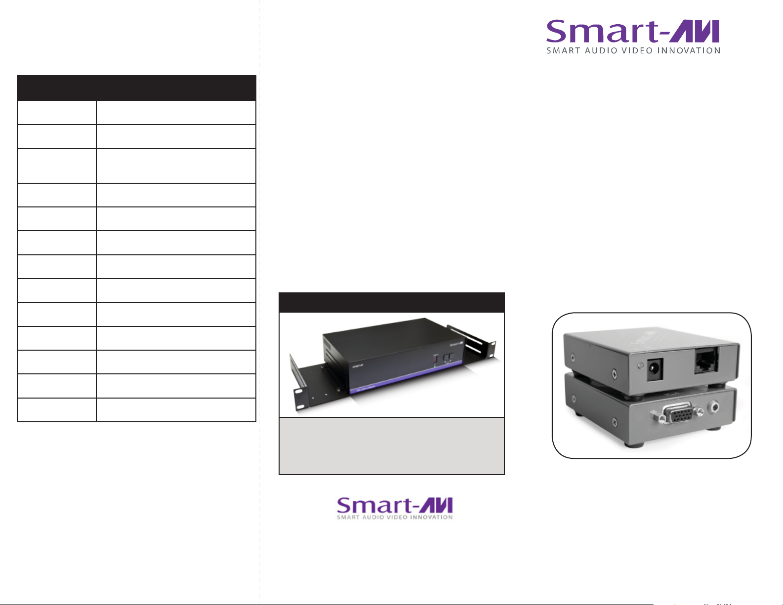
Technical Specifications
XP-AV SPECIFICATIONS
VGA Data
Format RGBHV, RGsB, YUV, Y/C, CVBS
Resolution
Connector type HD 15 socket
Audio
Signal Type Stereo unbalanced
Connector 3.5mm jack socket
Power
Requirements 5VDC @.5A
Up to 1900 x 1200
VGA, SVGA, XGA, SXGA)
© Copyright 2011 Smart-AVI, All Rights Reserved
NOTICE
The information contained in this document
is subject to change without notice. Smart-AVI makes
no warranty of any kind with regard to this material,
including but not limited to, implied warranties of
merchantability and fitness for any particular purpose.
Smart-AVI will not be liable for errors contained herein or for
incidental or consequential damages in connection with the
furnishing, performance or use of this material.
No part of this document may be photocopied, reproduced or
translated into another language without prior written consent
from Smart-AVI.
For more information, visit www.smartavi.com.
Rack Mountable Option
User Manual
XT-AV
Connector 2.1mm DC jack (center +ve)
Physical
Dimensions 135 x 90 x 23mm (26 with pegs)
Weight .8 lbs or .36 kg
Our SmartRack is the perfect solution to allow
virtually all SmartAVI devices to be custom mounted
in a standard 19” server rack. The SmartRack is fully
adjustable and can secure/organize several devices.
SmartAVI, Inc. / Twitter: smartavi
11651 Vanowen St. North Hollywood, CA 91605
Tel: (818) 503-6200 Fax: (818) 503-6208
http://www.SmartAVI.com
Use a single CAT5 to broadcast high
resolution SXGA and Stereo Audio up
to 1000ft away.
www.smartavi.com
Page 2
Introduction
Preparing & Connecting System CAT5 Cable
Following is the wiring standard for terminating CAT 5 cable
using RJ-45 connector:
Pair 1 Pins 1 & 2
Pair 2 Pins 3 & 6
Pair 3 Pins 4 & 5
Pair 4 Pins 7 & 8
Connectors: RJ-45
Capacitance: 14 pf/ft (46.2 pf/m)
Conductor Gauge: 24 AWG
Impedance: 100 +/- 15 ohms
4 - Pair
Connecting The Transmitter
1. Connect the output of the computer video card to the
video input of the transmitter using the included male
to male video cable.
2. Connect the output of the computer audio card to the
audio input of the transmitter using 3.5mm audio
male to male audio cable.
3. Connect external speakers to the transmitter’s audio
out (Standard 3.5mm stereo miniplug).
4. In the back of the unit connect the CAT5 cable that
will connect to the receiver (XTAV-RX).
Connecting The Receiver
Connect CAT5 cable (coming from the transmitter) 1.
to the back of the receiver.
Connect display monitors to the VGA out connec-2.
tor on the front of the receiver.
Connect external speakers to the audio 3.
output connections on the front of the unit.
(Standard 3.5mm stereo Miniplug)
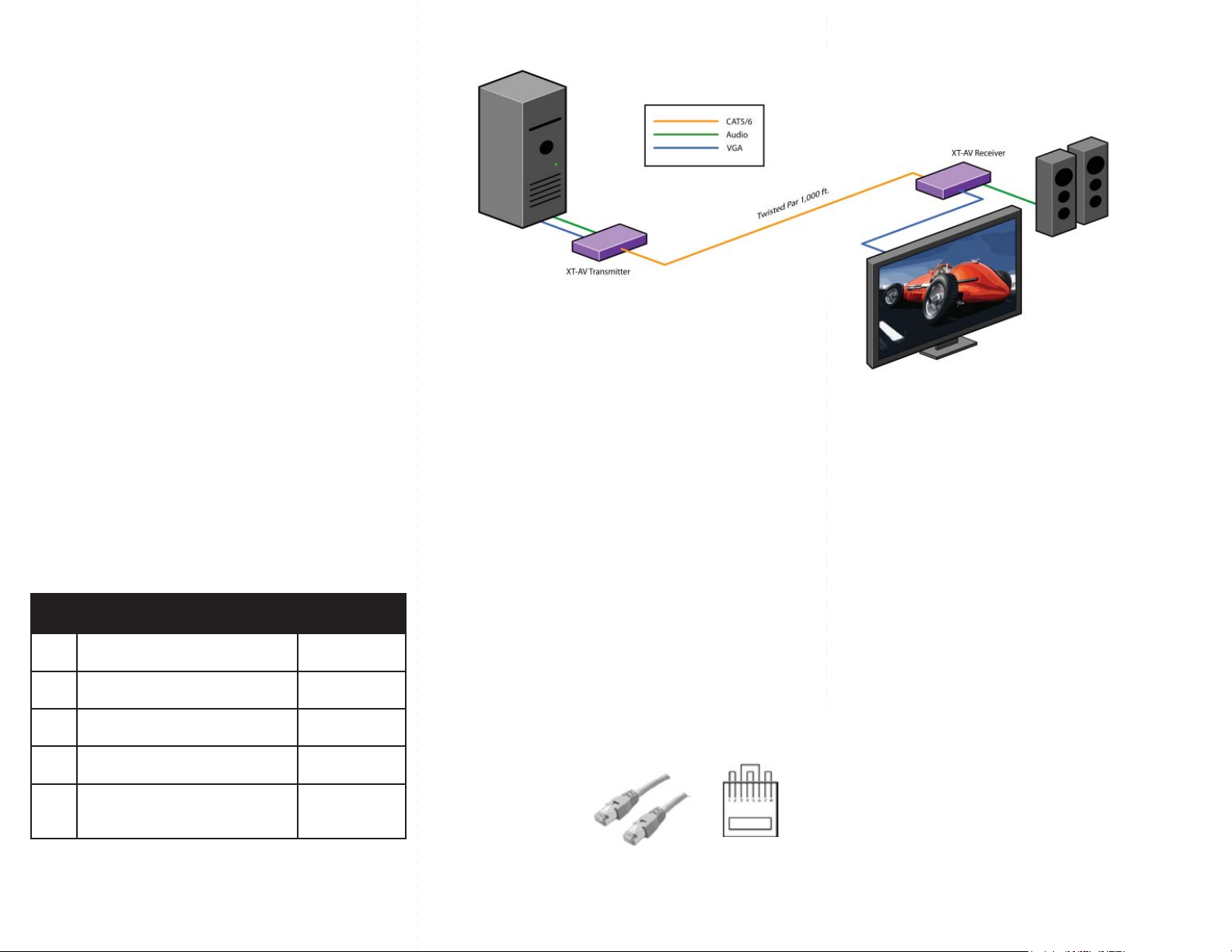
Installation Diagram
Preparing & Connecting System CAT5 Cable
Following is the wiring standard for terminating CAT 5 cable
using RJ-45 connector:
Pair 1 Pins 1 & 2
Pair 2 Pins 3 & 6
Pair 3 Pins 4 & 5
Pair 4 Pins 7 & 8
Connectors: RJ-45
Capacitance: 14 pf/ft (46.2 pf/m)
Conductor Gauge: 24 AWG
Impedance: 100 +/- 15 ohms
4 - Pair
Installation Diagram
DVD Player
IR
HDX-PRO Transmitter Unit
Cat 5
Audio
Video
The XT-av range of products allows the extension of
a wide range of video and audio formats via a single
Category 5 Unshielded Twisted Pair (UTP) cable.
Features
Uses easy to install, inexpensive CAT-5/5e/6/7/8.
Output reaches up to 1,000 feet (300 m).
Resolutions up to 1900x1200.
300 MHz Bandwidth.
Sends high-resolution UXGA, Stereo Audio and
Compatible with VGA, XGA, Sun, MAC and SGI
Sync Format / Polarity Preservation.
Compatible with Line Level Stereo Audio Signals.
High ground loop immunity.
Built-in lightning, power surge and transient
protection.
Designated trimmer in the remote unit to
compensate for cable length.
Compact Metal Case Enclosure.
What’s in the box?
XT-AV
Please check the contents of the package before
beginning installation.
XT-AV Package Content
Qty Items Part No.
1 XT-AV Transmitter unit XTAV-TX
1 XT-AV Receiver unit XTAV-RX
2 5 volt dc power supply PS-5D1A-US
HDD 15 male to male VGA cable
1
(6ft)
CC-VGAMM-06
Installation Diagram
Connecting The Transmitter
1. Connect the output of the computer video card to the
video input of the transmitter using the included male
to male video cable.
2. Connect the output of the computer audio card to the
audio input of the transmitter using 3.5mm audio
male to male audio cable.
3. Connect external speakers to the transmitter’s audio
out (Standard 3.5mm stereo miniplug).
4. In the back of the unit connect the CAT5 cable that
will connect to the receiver (XTAV-RX).
Connecting The Receiver
Connect CAT5 cable (coming from the transmitter) 1.
to the back of the receiver.
Connect display monitors to the VGA out connec-2.
tor on the front of the receiver.
Connect external speakers to the audio 3.
output connections on the front of the unit.
(Standard 3.5mm stereo Miniplug)
Preparing & Connecting System CAT5 Cable
Following is the wiring standard for terminating CAT 5 cable
using RJ-45 connector:
Pair 1 Pins 1 & 2
Pair 2 Pins 3 & 6
Pair 3 Pins 4 & 5
Pair 4 Pins 7 & 8
Connectors: RJ-45
Capacitance: 14 pf/ft (46.2 pf/m)
Conductor Gauge: 24 AWG
Impedance: 100 +/- 15 ohms
4 - Pair
Adjusting and Tuning the SignalAdjusting and Tuning the Signal
Adjusting and Tuning the Signal
Adjusting and Tuning the SignalAdjusting and Tuning the Signal
In order to fine tune the signal, adjust the individual
dials one at a time starting with GREEN, then BLUE,
and lastly RED. As you turn the dials you will notice
the colors slightly change as you increase or decrease
the strength. All dials should be around the same
distance.
 Loading...