

Page 1
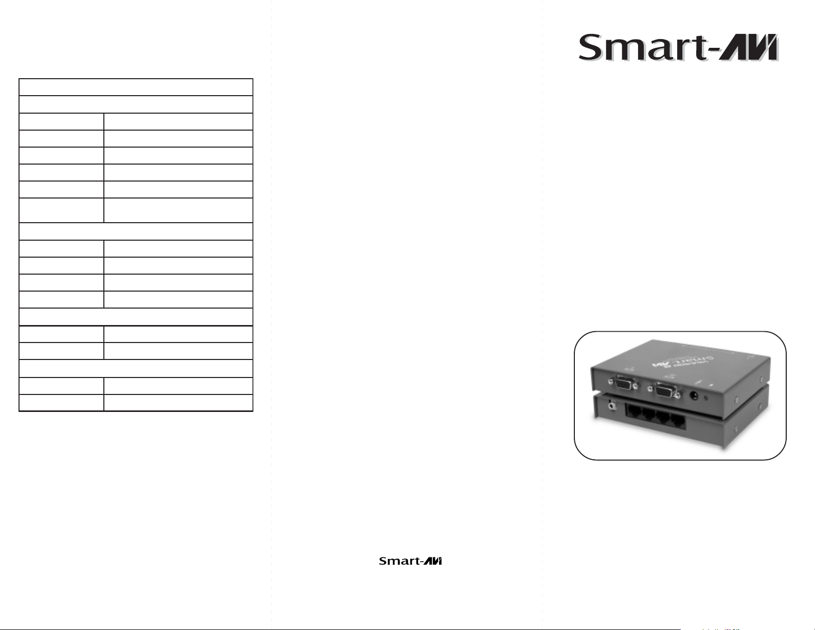
Technical Specifications
3MART!UDIO6IDEO)NTEGRATION
3MART!UDIO6IDEO)NTEGRATION
© Copyright 2007 Smart-AVI, All Rights Reserved
oediVoediV
oediVoediV
oediV
htdiwdnaBzHM004
leveLlangisgolanAtlov1
ecnadepmIsmho57
rotcennoC51DHytisnedhgiH
tamroFBsGR/HBGR/AGXU/AGX/AGVS/
cnyS
oiduAoiduA
oiduAoiduA
oiduA
htdiwdnaBzHK02
levellangiSBdO
ecnadepmIsmhoK01
rotcennoCtekcoskcajmm5.3
elbaCmetsySelbaCmetsyS
elbaCmetsySelbaCmetsyS
elbaCmetsyS
epyTA865AIEPTU5taC
rotcennoC54JR
rewoPrewoP
rewoPrewoP
rewoP
stnemeriuqeRAm005@CDV5
rotcennoCkcaJCD1.2x5
reviecerdnarettimsnarTreviecerdnarettimsnarT
reviecerdnarettimsnarTreviecerdnarettimsnarT
reviecerdnarettimsnarT
AGV
zHK031ot51:egnaRcnySlatnozirohLTT
zH021ot03egnaRcnySlacitreV
Notice
The information contained in this document is
subject to change without notice. Smart-AVI makes
no warranty of any kind with regard to this material,
including but not limited to, implied warranties of
merchantability and fitness for any particular
purpose.
Smart-AVI will not be liable for errors contained herein
or for incidental or consequential damages in
connection with the furnishing, performance or use
of this material.
No part of this document may be photocopied,
reproduced or translated into another language with
out prior written consent from Smart-AVI.
For the complete manual, visit www.smartavi.com.
User Manual
VCA400
3111 Winona Ave., Suite 101
Burbank, California 91504
Phone: (818) 565-0011
Facsimile: (818) 565-0020
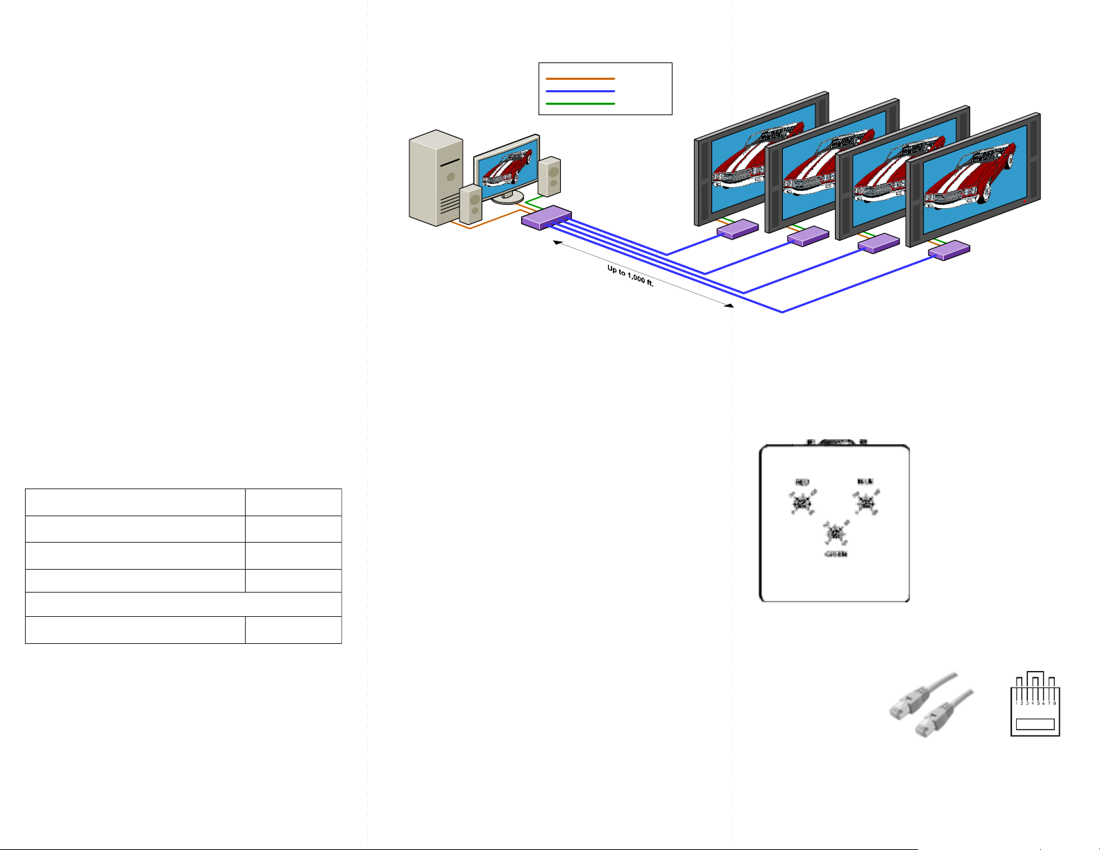
Use a single CAT5 to broadcast high
resolution UXGA and stereo audio to 4
locations1000ft away
www.smartavi.com
Page 2
Introduction
The VCA400 allows transmission of high definition
video and stereo audio signals over a standard CAT5 UTP cable over distances of up to 1000 ft.
Features
Uses easy to install, inexpensive CAT5.
Output reaches up to 1,000 feet.
Resolutions up to 1900x1200.
300 MHz Bandwidth.
Sends high-resolution VGA and stereo audio
signals from one source to up to 4 devices.
Compatible with VGA, XGA, Sun, MAC and SGI
signals.
Sync Format / Polarity Preservation.
High ground loop immunity.
Built-in lightning, power surge and transient
protection.
Designated trimmer in the remote unit to
compensate for cable length.
Compact Metal Case Enclosure.
Remote Units come with Buffered Outputs.
External power supply.
Installation Diagram
VCAT Transmitter Installation Diagram
XVGA
Cat 5
Audio
VCAT Receiver Installation Diagram
What’s in the box?
noitpircseDrebmuNtraP
ylppuSrewoPA1CDV5SU-A1D5-SP
GV60-MMAGV-CC
tinUrevieceRXR-TACV001XR-ACV
Connecting The TransmitterConnecting The Transmitter
Connecting The Transmitter
Connecting The TransmitterConnecting The Transmitter
1. Connect the output of the computer video card to the
video input of the transmitter using the included male
to male video cable.
2. Connect local monitor to the VGA out of the
transmitter.
rettimsnarToiduA/AGXUACVtrop4004XT-ACV
elameFotelaMelbacA
tnempiuqElanoitpOtnempiuqElanoitpO
tnempiuqElanoitpOtnempiuqElanoitpO
tnempiuqElanoitpO
3. Connect the audio output cable from the computer
to the transmitter
4. In the back of the unit connect the CAT5 cable that
will connect to the receiver unit.
5. Connect the power supply.
*NOTE: You can not use RS232 and IR at the same time.
Connecting The ReceiverConnecting The Receiver
Connecting The Receiver
Connecting The ReceiverConnecting The Receiver
1. Connect CAT5 cable (coming from the transmitter) to
the back of the receiver.
2. Connect monitors to the VGA out connectors on the
front of the receiver.
3. Connect the speakers to the audio out connectors on
the front of the receiver unit.
4. Connect the power supply.
Adjusting and Fine Tuning the SignalAdjusting and Fine Tuning the Signal
Adjusting and Fine Tuning the Signal
Adjusting and Fine Tuning the SignalAdjusting and Fine Tuning the Signal
In order to fine tune the
signal, adjust the individual
dials one at a time starting
with GREEN, then BLUE,
and lastly RED. As you turn
the dials you will notice the
colors slightly change as
you increase or decrease
the strength.
Preparing & Connecting System CAT5 CablePreparing & Connecting System CAT5 Cable
Preparing & Connecting System CAT5 Cable
Preparing & Connecting System CAT5 CablePreparing & Connecting System CAT5 Cable
Following is the wiring standard for terminating CAT 5
cable using RJ-45 connector:
Pair 1 Pins 1 & 2
Pair 2 Pins 3 & 6
Pair 3 Pins 4 & 5
Pair 4 Pins 7 & 8
Connectors:Connectors:
Connectors: RJ-45
Connectors:Connectors:
Capacitance:Capacitance:
Capacitance: 14 pf/ft (46.2 pf/m)
Capacitance:Capacitance:
Conductor Gauge:Conductor Gauge:
Conductor Gauge: 24 AWG
Conductor Gauge:Conductor Gauge:
Impedance:Impedance:
Impedance: 100 +/- 15 ohms
Impedance:Impedance:
4 - Pair
 Loading...