

Page 1
Mosaic Manual
SmartAVI
3111 Winona Ave., Suite 101 Burbank, California 91504
Tel: (818) 565-0011 • Fax: (818) 565-0020 • Email: info@smartavi.com
Page 2

2
Page 3

Contents
Contents................................................................................................... 3
Introduction .............................................................................................. 4
Specification............................................................................................. 5
Unpacking ................................................................................................ 6
Installing the Mosaic Card ........................................................................ 7
Installing the Mosaic with the Horizon and iH Card .................................. 8
Enabled outputs .................................................................................. 11
How To Connect Video Inputs ........................................................... 13
Connection Table............................................................................... 14
How To Get The Best Quality Video Windows From the Mosaic............ 16
Using more than 1 Mosaic Card......................................................... 19
Further Improvements ...................................................................... 21
Recommended products for this example: ....................................... 22
Software: .......................................................................................... 22
Software Installation ............................................................................... 23
From the CD .................................................................... 23
Accessories............................................................................................ 24
Mosaic Buffer Module (MBM)............................................................. 24
SmartAVI................................................................................................ 26
Technical Support .............................................................................. 26
Copyright Statement .......................................................................... 26
Index ...................................................................................................... 28
3
Page 4

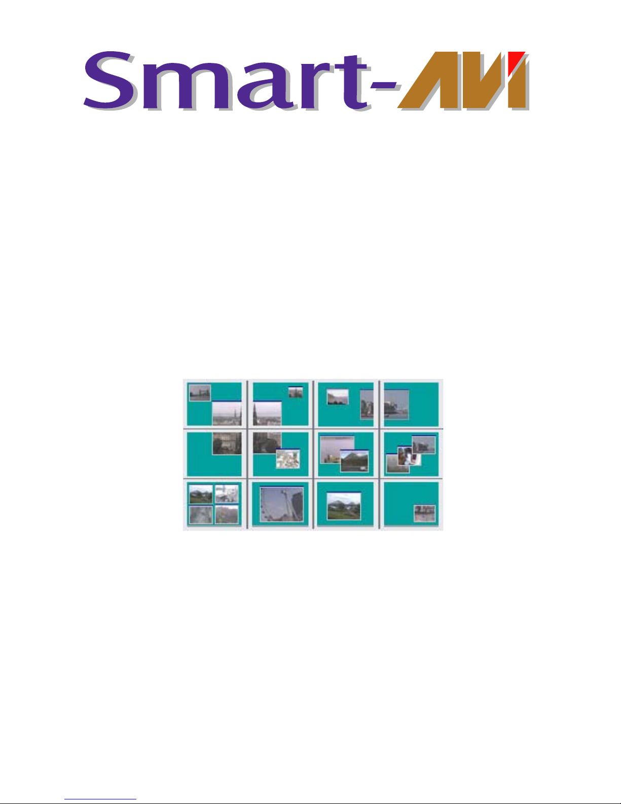
Introduction
The Mosaic is a PCI plug-in card which has been designed to operate in
conjunction with the Horizon 4VW-DIG and the iH4-DIG
graphics card. The Mosaic card, when combined with the Horizon 4VWDIG and iH4, provides up to 9 separate video overlay windows.
For systems that require more than 9 overlay windows a second Mosaic
card may be installed providing up to 18 windows.
The Mosaic is supplied with driver software for Windows® 2000 and XP.
The Wall Control application program is provided enabling users to
control the video overlay windows or, for users who wish to control the
Mosaic card from their own software, an SDK is also provided.
4
Page 5

Specification
Card Type PCI 2.2 compliant adapter
Card Size 100 x 260 (mm)
Max Number of Video Windows 9
Supported Video Formats PAL, NTSC, SECAM, S-Video
Power consumption 12 watts
Power Requirements +5V at 2.2Amps, +12V at 100mA
Inputs per overlay window 2 x Composite or
1 x Composite and 1 x S-Video
Max capture resolution per
channel
768 x 288
5
Page 6

Unpacking
Your packing box should contain the following items:
• The Mosaic PCI plug-in card.
• 2 x multi-way splitter cables. (BNC 16 - Cable)
• 2 x M-cable-4s. (40 way Ribbon Cables)
Notes:
All plug-in cards are static sensitive and are packed in anti-static
materials. Please keep the card in its packaging until you are ready
to install.
We recommend that you do not discard the packing box until you
are completely satisfied with the Mosaic, and it is fully installed and
working correctly. We also recommend that you make note of the
serial number of the card in a prominent place before you plug the
card into the computer. This should hasten any query should you
need to contact our Technical Support Department. The serial
number is displayed on the card and the box label.
6
Page 7

Installing the Mosaic Card
Note:
You are likely to need a flat blade and a Phillips head screwdriver
for the installation so please ensure you have these to hand before
you begin.
• Power down your complete system (including peripherals) at the
PC and the main power supply.
• Disconnect all the cables connected to the PC, noting the positions
for correct reconnection after the Mosaic card is installed.
Carefully remove the cover from your PC.
• Locate an available PCI slot to install your Mosaic card preferably
next to your Horizon 4VW-DIG or iH4-DIG. You may need to
remove the expansion slot cover and screw, please retain these
for future use.
• Holding the card firmly by its top edge at each end of the card’s
length, slide it into the slot.
• Using the retaining screw, secure the bracket to the back panel.
• Replace the cover on your PC
7
Page 8

Installing the Mosaic with the Horizon and iH
Card
The Mosaic is connected to the Horizon 4VW-DIG or iH4-DIG
cards via inter-card ribbon cables, enabling the video overlays to select
upto 9 possible video sources. The Mosaic supports up to 8 Horizon
4VW-DIG or 8 iH4-DIG cards
• Install and configure all the required Horizon 4VW-DIG or iH4-DIG
cards in the system, carefully following the installation instructions.
Ensure that your multi-screen system is working correctly before
installing the Mosaic card.
• Install the Mosaic card as described in Installing The Mosaic Card
• Once the Mosaic is installed it can be connected to the Horizon
4VW-DIG or iH4-DIG cards in the system.
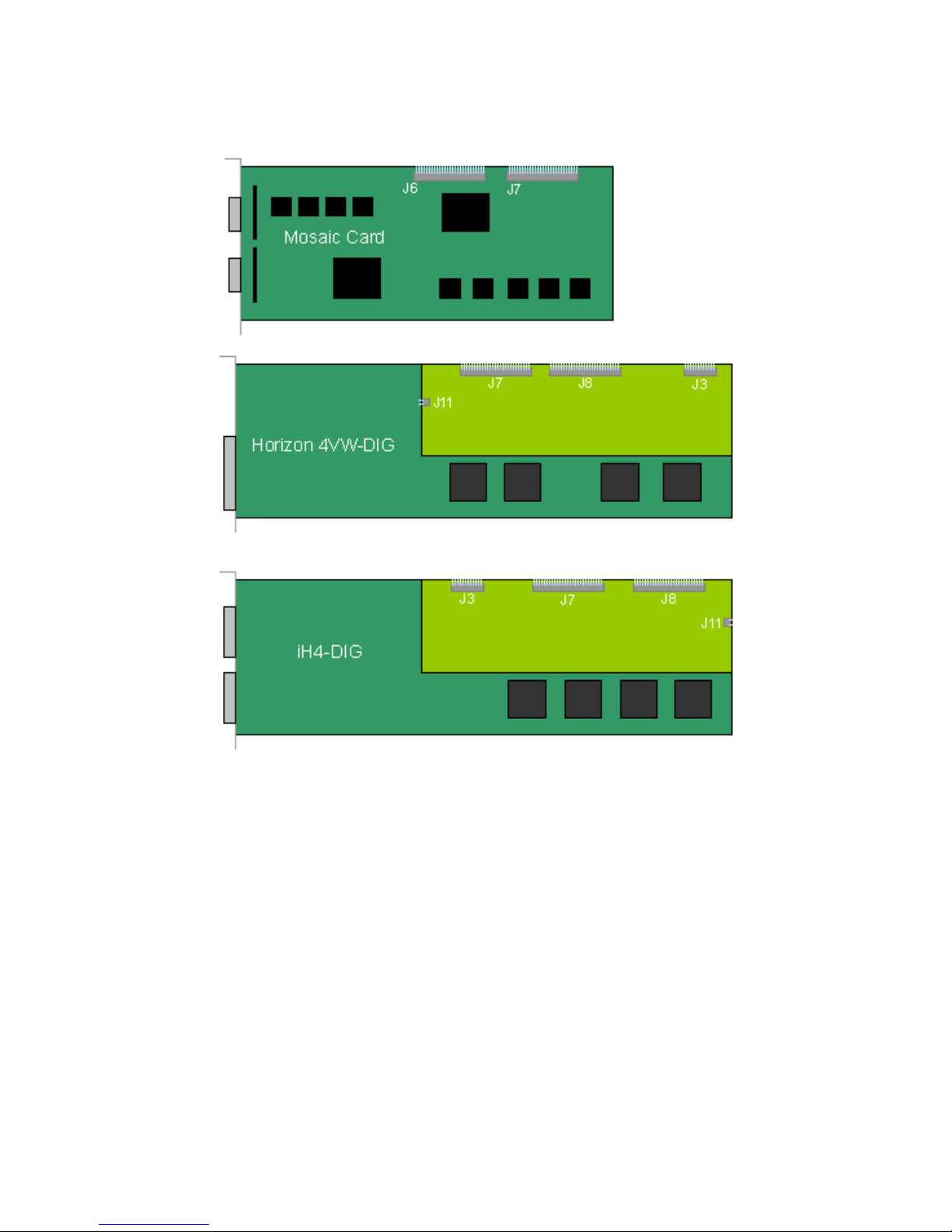
Connect the 2 x 40 way ribbon cables from the Mosaic card to the
Horizon 4VW-DIG or iH4-DIG cards. The Mosaic card should be
connected to one end of the ribbon cable. The headers on the Mosaic
cards are marked J6 and J7 and should be connected to the graphics
cards as follows:
Connect the J6 header on the Mosaic to the J7 headers on the graphics
card.
Connect the J7 header on the Mosaic to the J8 headers on the graphics
cards.
The illustration on the next page details the location of the headers on
each of the cards:
8
Page 9
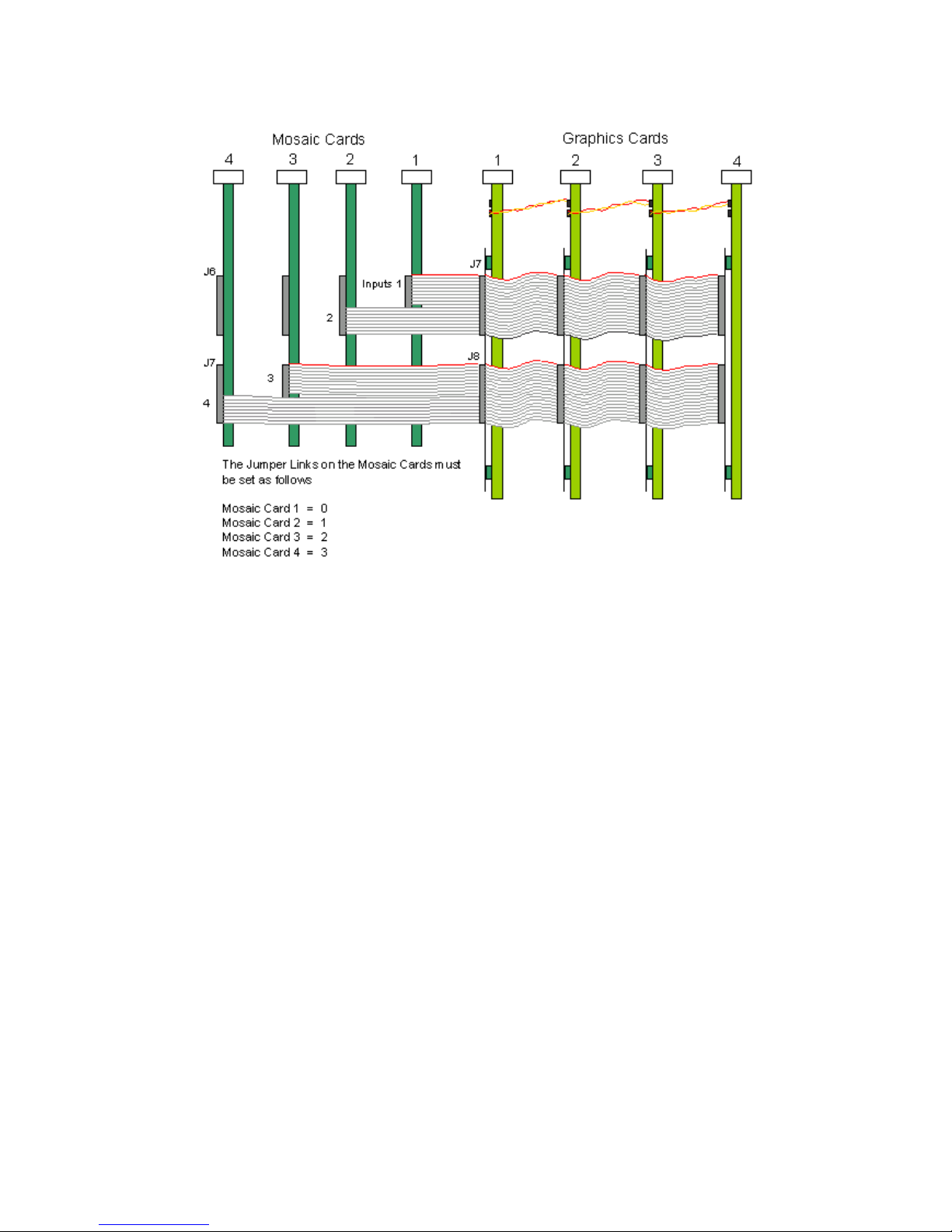
Note:
It is imperative that the Jumper Link (J11) on the Graphics card is
removed from all the cards except the last one, the last one being
the card located furthest away from the Mosaic card. This provides
the clock termination for digital video bus supplied by the Mosaic
card.
The header J5 located on the Mosaic card is for factory use only.
Do not connect to this header.
There are numerous ways in which the Mosaic Card can be connected to
the graphics card, the basic rules are:
• The Mosaic will connect upto a maximun of 8 cards. The Mosaic
video window will only display on the screens driven by the
graphics cards it is connected to.
9
Page 10

The illustrations on the next page demonstrate the simple and most
common arrangements made with the Mosaic.
There are many variations with many options to display the Mosaic video
windows. The maximum possible would be 8 graphics cards and 32
Mosaic cards, this would provide a total of 288 Mosaic video windows
and 32 displays. Each graphics card would be connected to 4 Mosaic
cards offering 36 video windows for each group of 4 displays.
This configuration would give the following display option:
• 9 Mosaic overlay displayed anywhere across 12 screens.
10
Page 11

This configuration would offer the following display option:
• 18 Mosaic overlays displayed anywhere across 12 screens.
Note: Overlay windows from different Mosaic cards cannot be
displayed on the same screen.
Enabled outputs
Each Mosaic card has 4 outputs, up to 9 Mosaic windows can be
displayed through each card. When connecting more than one Mosaic
card, each output has to be connected separately otherwise the Mosaic
video windows will not be displayed.
If the system has 4 Mosaic cards connected to 4 graphics cards only one
output from each Mosaic card header can be connected. The illustration
below shows how this configuration is connected.
11
Page 12
Connected this way the outputs from each Mosaic card are as follows:
• Mosaic Card 1 - Output 1
• Mosaic Card 2 - Output 2
• Mosaic Card 3 - Output 3
• Mosaic Card 4 - Output 4
12
Page 13

How To Connect Video Inputs
Each video input is channeled to a specific window, each video window is
displayed by selecting a specific window from the application software,
therefore it is important that the video inputs are connected correctly.
The windows each have three inputs that can be utilised as follows:
• Composite A / Luma
• Composite B
• Chroma
If you wanted to connect a specific composite input to window 9 then you
would connect the input to the BNC cable, number 1 on the bottom
splitter cable.
If you wanted to connect an S-Video input to window 4, then you would
connect the 2 S-Video inputs into the BNC number 7 and 8 (Chroma and
Luma) on the top splitter cable.
The following table describes how to connect the video inputs to the
specific Mosaic video windows and which jumper link on the Mosaic card
provides the 75ohm termination for each input. The links should be fitted
to apply termination. (All links are fitted as standard.)
13
Page 14

Connection Table
Mosaic
Window
Input Cable BNC N0
Terminating Link
(75 ohm)
1 Composite A/Luma Top 1 LK 1
1 Chroma Top 2 LK 2
1 Composite B Bottom 3 LK 17
2 Composite A/Luma Top 3 LK 3
2 Chroma Top 4 LK 4
2 Composite B Bottom 4 LK 18
3 Composite A/Luma Top 5 LK 5
3 Chroma Top 6 LK 6
3 Composite B Bottom 5 LK 18
4 Composite A/Luma Top 7 LK 7
4 Chroma Top 8 LK 8
4 Composite B Bottom 6 LK 19
5 Composite A/Luma Top 9 LK 9
5 Chroma Top 10 LK 10
5 Composite B Bottom 7 LK 20
6 Composite A/Luma Top 11 LK 11
6 Chroma Top 12 LK12
6 Composite B Bottom 8 LK 21
7 Composite A/Luma Top 13 LK 13
7 Chroma Top 14 LK 14
7 Composite B Bottom 9 LK 23
8 Composite A/Luma Top 15 LK 15
8 Chroma Top 16 LK 16
8 Composite B Bottom 10 LK24
14
Page 15

9 Composite A/Luma Bottom 1 LK 25
9 Chroma Bottom 2 LK 26
9 Composite B Bottom 11 LK 27
When installing multiple Mosaic cards in your machine it is
important that the jumper links LK28, LK29, LK30 and LK31 located
on the Mosaic cards are configured correctly for the number of
Mosaic cards in use.
The following table shows how to configure the jumper settings for
multiple Mosaic cards
LK 31 LK 30 LK 29 LK 28 Mosaic Card
0 0 0 0 1st Mosaic
0 0 0 1 2nd Mosaic
0 0 1 0 3rd Mosaic
0 0 1 1 4th Mosaic
0 1 0 0 5th Mosaic
0 1 0 1 6th Mosaic
0 1 1 0 7th Mosaic
0 1 1 1 8th Mosaic
1 0 0 0 9th Mosaic
1 0 0 1 10th Mosaic
1 0 1 0 11th Mosaic
1 0 1 1 12th Mosaic
0 = Link Fitted
1 = Link Removed
15
Page 16

How To Get The Best Quality Video Windows
From the Mosaic
Example 1 shows a single screen with 3 Mosaic windows, shown in
yellow.
The software analyses the position and size of the Mosaic Window and
allocates each window to an overlay. Mosaic supports up to 4 overlays
but there can be only one overlay covering any particular screen.
In this example a single overlay would be generated that bounds the 3
Mosaic windows. The overlay size and position is shown as a broken line
(-----). In the following examples any window shown in YELLOW
indicates GOOD QUALITY.
Windows shown in Red indicates POOR QUALITY. The trick for best
quality is to position the windows such that the bounding overlay is as
small as possible.
Note: You cannot display 2 or more overlays on the same screen
and there is a maximum of 4 overlay’s available.
Example 1
Example 2
In this example a 4th Mosaic window is now opened on a 2 x 2 wall. The
new window is large and touches the same screen as the 3 small
windows. This creates poor quality overlays.
Mosaic can only use one overlay to produce this layout because 2
overlays cannot cover the same screen. The overlay has to bound all 4
windows and then be up-scaled to cover the screen area. The video
quality for the large window shown in yellow will be good. The 3 smaller
16
Page 17

windows have to be down-scaled because they occupy a small part of the
overlay and so quality will degrade.
To improve the quality of the 3 small Mosaic windows, reposition the
large window so that it does not have any contact with the same screen
as the 3 small Mosaic windows.
The illustration below shows that by repositioning the large yellow window
Mosaic is allowed to use 2 overlay outputs and maximise the quality of
the 3 small windows and maximises a second overlay for the large
window.
17
Page 18

Example 3
(4 x 3 wall with 1 Mosaic card and 9 windows)
Poor layout - Only 1 overlay can be used because the large window
touches all screens
By repositioning the large window so that it touches fewer screens,
Mosaic can allocate more overlays and quality will improve.
All 4 overlays can be used here dramatically improving the quality of the
small windows on the left of the wall. However, although the small
windows on the right are improved, they are still not ideal
18
Page 19

If the large window is now repositioned such that it touches even fewer
screens then the quality will improve further. Also, move the window on
screen 5 nearer to the window on screen 1.
The 4 overlays are all used making best use of each overlay. All
windows should be of good quality.
This layout is almost the same as the starting layout but the video quality
has greatly improved.
Always try and make the Mosaic window as large as possible
relative to the size of the overlay that bounds the window(s).
The resolution of each Mosaic window is the ratio of it’s horizontal
and vertical size when compared to the size of the overlay that
bounds the window. The resolution of the overlay is always 768 x
567 so if the Mosaic window is tiny in proportion to the overlay, the
resolution of the Mosaic window will be small and of low quality.
Using more than 1 Mosaic Card.
The same rules apply when you use more than 1 Mosaic card, however,
the number of overlays for each card reduces, so this means that greater
care is required with window positioning to obtain optimum quality. Also,
video windows from different Mosaic cards cannot be placed on the same
screen.
• 2 Mosaic Cards = 2 overlays per card.
• 4 Mosaic cards = 1 overlay per card.
Example showing 2 Mosaic cards on a 4 x 3 wall
A = Window from Mosaic card A
19
Page 20

B = Window from Mosaic card B
The layout is not possible because the overlay bounding areas overlap.
The windows shown in purple will not display any video. Also, because
the large windows touch the same screen as the smaller windows, quality
will be bad. With this layout each Mosaic cards would generate only 1
overlay.
In order to be able to display all the windows first change the
window order as follows:
Now each Mosaic card will generate a single overlay containing all the
windows. Quality is still bad because the large windows touch the top
row of screens. This stops the Mosaic cards from being able to use their
second overlay.
20
Page 21

In order to be able to display all the windows first change the
window order as follows:
Now each Mosaic card will generate a single overlay containing all the
windows. Quality is still bad because the large windows touch the top
row of screens. This stops the Mosaic cards from being able to use their
second overlay
Further Improvements
One problem when using multiple Mosaic cards is that it is difficult to
display a particular video source in any window position without upsetting
the quality.
21
Page 22

A solution for this issue is to input all video sources into the VisionSwitch
card and then connect the Mosaic card inputs to the output on the
VisionSwitch.
With this configuration any video source can now be routed to any of the
Mosaic windows without disturbing the layout. Also, it is possible to
display any input multiple times.
In the example shown the small window could be pre-views of 16 video
sources with larger windows being able to select any of the pre-view
windows for display at higher resolution.
Recommended products for this example:
Hardware requirements:
• 3 x Horizon 4VW-DIG or iH4-DIG cards (12 screen wall).
• 2 x Mosaic cards with M2H4 cable set (18 video windows)
• 1 x VisionSwitch32-SA (Video switch with 32 inputs and 32
outputs).
VisionSwitch32-SA connection details:
• Connect up to 32 video sources to the inputs of the
VisionSwitch32 card.
• Connect outputs 1 to 9 to the 9 inputs of Mosaic card A.
• Connect outputs 10 to 18 to the 9 inputs of Mosaic card B.
Note: VisionSwitch32 outputs 19 to 32 are not used. You could use
these outputs if you wanted to add another Mosaic card to the
system.
Software:
Use the Wall Control application to select which video source goes to
each Mosaic window.
22
Page 23

Software Installation
The Mosaic drivers and application software can be installed on your
system using one of the following methods:
• The CD supplied with the Mosaic Card.
From The CD
Insert the CD into your CD ROM drive, the CD will autorun,
select install Mosaic driver. Or from either the Run menu option or using
Explore to browse the CD, locate the setup program, e.g.
d:/Mosaic/setup.exe.
Follow the Installation Wizard instructions as prompted.
Select the Save this file to disk option, click on OK and follow the
download instructions.
Once the download is complete, unzip the file, locate and double click on
the Mosaic setup.exe file and the installation process will commence.
Follow the Installation Wizard instructions as prompted.
Once the installation is complete, reboot the system.
23
Page 24

Accessories
Mosaic Buffer Module (MBM)
The Mosaic Buffer Module (MBM) is a small PCB that is attached to the
J3, J7 and J8 headers on the iH4-DIG enabling up to 8 iH4 cards to be
attached to your Mosaic cards.
The MBM is available in two models
MBM-H2 - Connects up to 4 Mosaic cards to up to 6 iH4-DIG cards.
24
Page 25

MBM-H4 - Connects up to 4 Mosaic cards to up to 8 iH4-DIG cards.
Below is an illustration showing how to connect 2 Mosaic cards to 6
iH4-DIG cards using the MBM-H2.
25
Page 26

SmartAVI
SmartAVI has a long and very successful history in the computer graphics
industry. SmartAVI has been designing and supplying high performance,
high quality graphics display systems to the worlds largest and most
demanding companies and institutions. SmartAVI was one of
the founding companies of multi screen Windows acceleration using
single and multi board solutions. Now, using the very latest display
technology SmartAVI offers some of the world's leading multi screen
graphics accelerators for the most demanding applications.
As new technology advances, so we at SmartAVI improve the
performance and functionality of both our hardware and software to give
our customers more. Following a continuous development program, we
pride ourselves on our support and responsive nature towards all our
customers and their changing needs. As more sophisticated equipment
and techniques become readily available, so we are there to exploit the
power and potential that this technology presents.
Technical Support
You can access our technical support staff by email or by using the
Problem Report form on the support page on the SmartAVI Web Site,
usually with a response within 24 hours (excluding weekends).
Via Email: Send an email to info@smartavi.com with
as much
information about your system as possible. To enable a swift response
we need to know the following details:
• Specification of the PC - including processor speed
• Operating System
• Application Software
• Hardware / Software
• The exact nature of the problem - and please be as specific as
possible.
Please quote version and revision numbers of hardware and software in
use wherever possible.
Copyright Statement
SmartAVI claims copyright on this documentation. No part of this
documentation may be reproduced, released, disclosed, stored in any
electronic format, or used in whole or in part for any purpose other than
stated herein without the express permission of SmartAVI.
Whilst every effort is made to ensure that the information contained in this
on-line help is correct, SmartAVI Limited make no representations or
warranties with respect to the contents thereof, and do not accept liability
for any errors or omissions. SmartAVI reserves the right to change
specification without prior notice and cannot assume responsibility for the
26
Page 27

use made of the information supplied. All registered trademarks used
within this documentation are acknowledged by SmartAVI.
© SmartAVI, 2006
SmartAVI
3111 Winona Ave., Suite 101
Burbank, California 91504
Tel: (818) 565-0011
Fax: (818) 565-0020
Email: info@smartavi.com
URL: http://smartavi.com
27
Page 28

Index
A
All links, 11
B
basic rules, 8
best quality, 14
Best Quality, 14
C
Card Size, 4
Card Type, 4
Chroma, 11
Composite A, 11
Composite A / Luma, 11
Composite B, 11
connect video inputs, 11
Connect Video Inputs, 11
Connection Table, 11
Copyright Statement, 21
D
E
Email, 21
Enabled output, 10
Enabled outputs, 10
F
French Office, 22
G
German Office, 22
H
headers, 7
Horizon 4VW-DIG, 7
I
iH4-DIG, 7
Installing the Mosaic Card, 6
28
Page 29

J
J5 Header, 8
Jumper Link (LK11), 8
jumper links, 12
jumper settings, 12
L
Luma, 11
M
Main Sales, 21
O
outputs, 10
P
packing box, 5
Power consumption, 4
Power Requirements, 4
R
Recommended products, 19
S
Supported Video Formats, 4
T
Technical Support, 21
U
UK Headquarters, 21
Using The Mosaic, 10
V
video window, 8
VisionSwitch32-SA connection, 19
W
Wall Control, 3
Wall Control application, 19
Wall Control Manual, 10
29
 Loading...