

Page 1
Technical Specifications
3MART!UDIO6IDEO)NTEGRATION
3MART!UDIO6IDEO)NTEGRATION
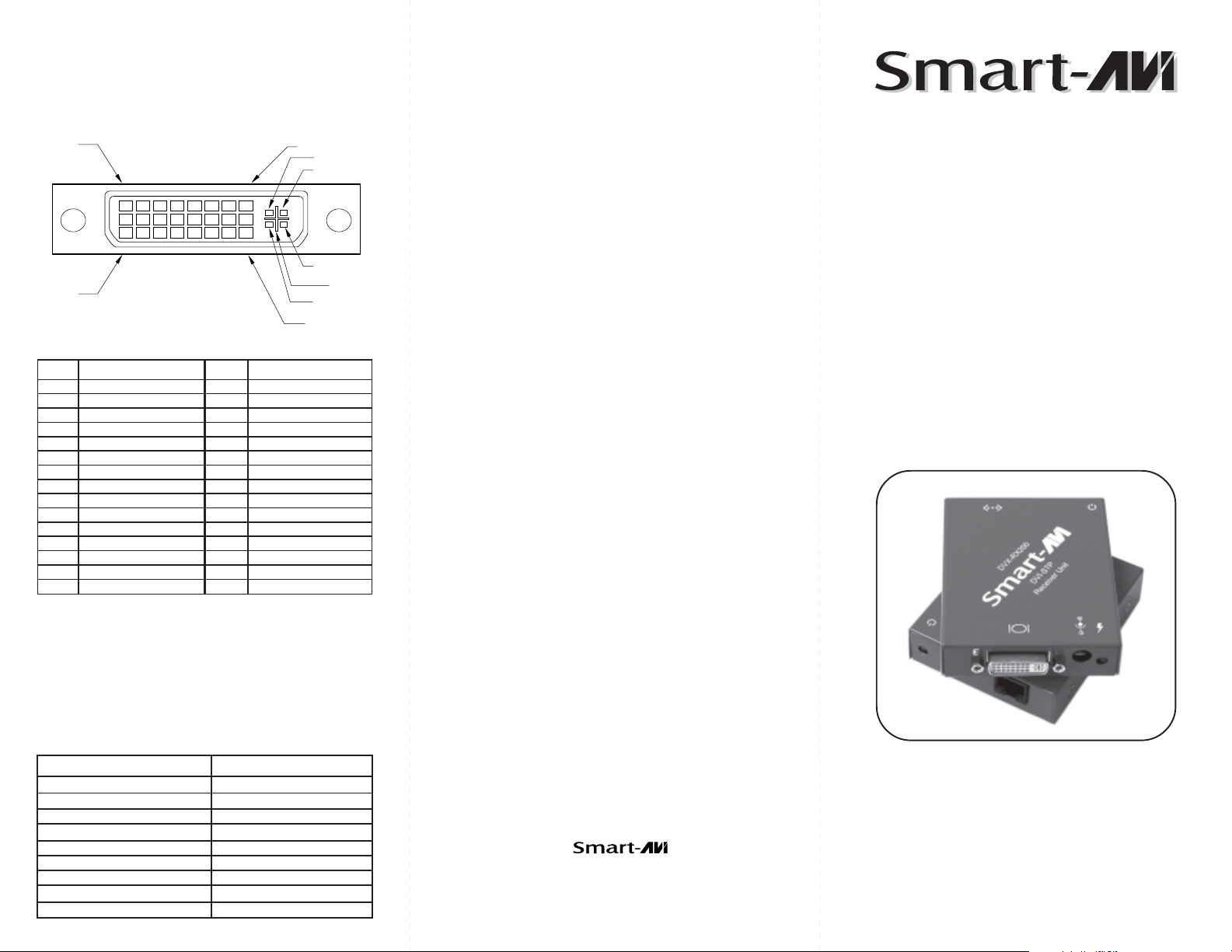
Input/Output Signal
© Copyright 2004 Smart-AVI, All Rights Reserved
Notice
PIN 1
PIN 17
PIN 8
PIN 24
C 1
C 2
C 4
C 3
C 5
#niPlangiS#niPlangiS
1-2ataDS.D.M.T61tceteDgulPtoH
2+2ataDS.D.M.T71-0ataDS.D.M.T
3dleihS4/2ataDS.D.M.T81+0ataDS.D.M.T
4-4ataDS.D.M.T91dle
5+4ataDS.D.M.T02-5ataDS.D.M.T
6kcolCCDD12+5ataDS.D.M.T
7ataDCDD22dleihSkcolCS.D.M.T
8cnyS.treVgol
anA32+kcolCS.D.M.T
9-1ataDS.D.M.T42-kcolCS.D.M.T
01+1ataDS.D.M.T
11dleihS3/1ataDS.D.M.T1CdeRgolanA
21-3ataDS.D.M.T2Cn
31+3ataDS.D.M.T3CeulBgolanA
5VDC 1.6A
41rewoPV5+4CcnySzroHgolanA
51DNG5CdnuorGgolanA
ihS5/0ataDS.D.M.T
eerGgolanA
The information contained in this document is
subject to change without notice. Smart-AVI makes
no warranty of any kind with regard to this material,
including but not limited to, implied warranties of
merchantability and fitness for any particular
purpose.
Smart-AVI will not be liable for errors contained herein
or for incidental or consequential damages in
connection with the furnishing, performance or use
of this material.
No part of this document may be photocopied,
reproduced or translated into another language with
out prior written consent from Smart-AVI.
User Manual
DVX-200
Resolutions
Supported by the internal EDID configuration
Resolution Refresh Rate
640 x 480 85 Hz
800 x 600 85 Hz
1024 x 768 85 Hz
1152 x 870 75 Hz
1280 x 768 75 Hz
1280 x 960 60 Hz
1280 x 1024 60 Hz
1600 x 1200 60 Hz
1920 x 1080 60 Hz
3111 Winona Ave., Suite 101
Burbank, California 91504
Phone: (818) 765-6000
Facsimile: (818) 765-6066
The DVX-200 extends any single-link
DVI-D signal up to 220 feet using
Cat 5e or Cat 6 shielded cable.
www.smartavi.com
Page 2
Introduction
The DVX-200 extends the distance between any
computer supporting single-link DVI-D and a
monitor or projector with a compatible DVI input.
Features
Supports Mac and PC DVI-D
Resolutions up to 1920 x 1080
No degradation of video quality
LEDs indicate power and loss of clock signal
External power supplies
Silent fanless operation
Applications
Perfect Image Quality at all Resolutions.
Call Centers (co-locate user’s computers).
Industrial (protection against pollution).
Information Terminals & Kiosks.
Airports (air traffic control, passenger
information systems).
Medical - using computer tomographs generates
strong magnetic fields, which make it impossible
to use monitors.
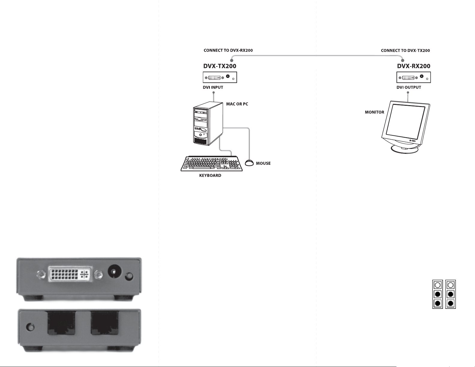
Front and Rear View
Installation Diagram
Installation
1. Turn off computer and monitor.
2. Connect DVI male to male cable between the
computer and the transmitter.
3. Connect monitor or projector to the DVI port
on the receiver.
4. Connect a shielded Cat 5e or Cat 6 cable
between port 1 on the transmitter and port 1
on the receiver.
5. Plug in the power transformers and connect
them to the transmitter and receiver.
6. Turn on the monitor and computer.
CAT5
UP TO 500FT
Optional DDC Pass-Through
If you would like the computer to read EDID
information directly from your monitor instead of
the internal EEPROM in the DVX-200, perform the
following steps.
1. Turn off computer and monitor.
2. Disconnect power adapters from transmitter
and receiver.
3. Remove screws on the sides of the transmitter.
4. Lift the top off of the chassis
5. Locate headers labeled J12 and J13.
J13 J12
6. Reconfigure the jumpers as shown.
7. Replace chassis top and screws.
8. Connect a second shielded Cat 5e or Cat 6 cable
between port 2 on the transmitter and port 2 on
the receiver.
 Loading...