

Page 1
Technical Specifications
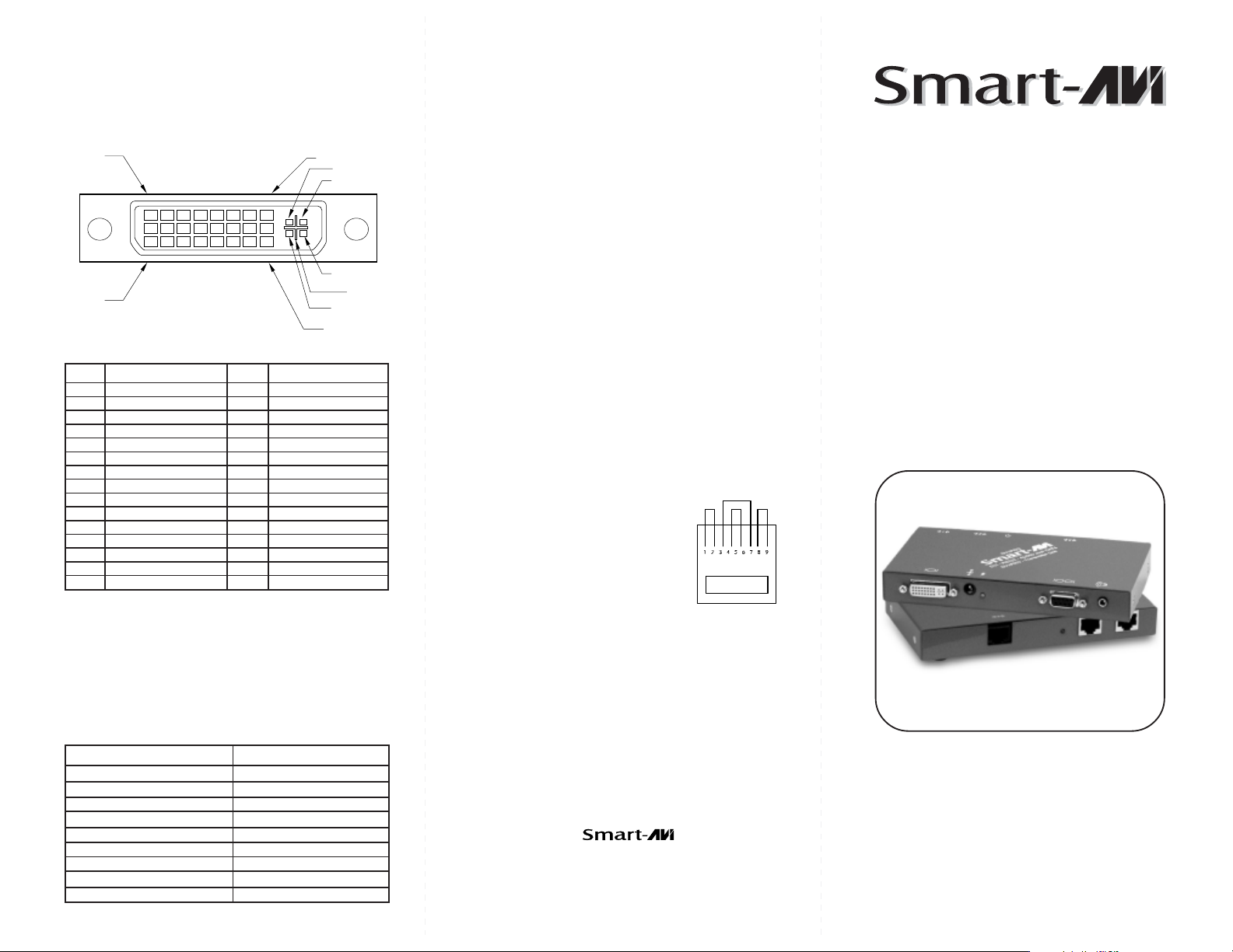
Input/Output Signal
PIN 1
PIN 17
#niPlangiS#niPlangiS
1-2ataDS.D.M.T61tceteDgulPtoH
2+2ataDS.D.M.T71-0ataDS.D.M.T
3dleihS4/2ataDS.D.M.T81+0ataDS.D.M.T
4-4ataDS.D.M.T91dleihS5/0ataDS.D.M.T
5+4ataDS.D.M.T02-5ataDS.D.M.T
6kcolCCDD12+5ataDS.D.M.T
7ataDCDD22dleihSkcolCS.D.M.T
8cnyS.treVgolanA32+kcolCS.D.M.T
9-1ataDS.D.M.T42-kcolCS.D.M.T
01+1ataDS.D.M.T
11dleihS3/1ataDS.D.M.T1CdeRgolanA
21-3ataDS.D.M.T2CneerGgolanA
31+3ataDS.D.M.T3CeulBgolanA
5VDC 1.6A
41rewoPV5+4CcnySzroHgolanA
51DNG5CdnuorGgolanA
PIN 8
PIN 24
C 1
C 2
C 4
C 3
C 5
© Copyright 2007 Smart-AVI, All Rights Reserved
Notice
The information contained in this document is
subject to change without notice. Smart-AVI makes
no warranty of any kind with regard to this material,
including but not limited to, implied warranties of
merchantability and fitness for any particular
purpose.
Smart-AVI will not be liable for errors contained herein
or for incidental or consequential damages in
connection with the furnishing, performance or use
of this material.
No part of this document may be photocopied,
reproduced or translated into another language with
out prior written consent from Smart-AVI.
Prepairing System CAT6 CablePrepairing System CAT6 Cable
Prepairing System CAT6 Cable
Prepairing System CAT6 CablePrepairing System CAT6 Cable
Pair 1 Pins 1 & 2
Pair 2 Pins 3 & 6
Pair 3 Pins 4 & 5
Pair 4 Pins 7 & 8
Connectors: RJ-45
Capacitance: 14 pf/ft (46.2 pf/m)
Conductor Gauge: 24 AWG
Impedance: 100 +/- 15 ohms
4 - Pair, (stranded) Foil Shielded
3MART!UDIO6IDEO)NTEGRATION
3MART!UDIO6IDEO)NTEGRATION
User Manual
DVX-PRO
Resolutions
Supported by the internal EDID configuration
Resolution Refresh Rate
640 x 480 85 Hz
800 x 600 85 Hz
1024 x 768 85 Hz
1152 x 870 75 Hz
1280 x 768 75 Hz
1280 x 960 60 Hz
1280 x 1024 60 Hz
1600 x 1200 60 Hz
1920 x 1200 60 Hz
3111 Winona Ave., Suite 101
Burbank, California 91504
Phone: (818) 565-0011
Facsimile: (818) 565-0020
The DVX-PRO extends any DVI-D signal,
full duplex RS232 and stereo sound up
to 250ft with Cat6 STP cable
www.smartavi.com
Page 2
Introduction
The DVXPRO extends the distance between any
computer supporting single-link DVI-D and a
monitor or projector with a compatible DVI input.
Features
Top Image Quality at all Resolutions.
Video Resolutions up to 1920 x 1200 @ 60Hz
(1280 x 1024 @ 75Hz). on all distances up to
the maximum distance.
User selectable: DCC-Information used from
the remotely located monitor, from the locally
located Monitor or from an internal DDC
Table.
Basic device to remotely locate Touch Screen
and Sound.
Full duplex RS232 up to 150kbps.
Maximum Screen Resolution on all distances:
250 ft w/ STP Cat5e.
Compatible with all operating systems.
Compatible with all major Touch Screen and
Tablet.
Rack Mount options (19”): Mount up to 4 de-
vices in a 19”/1U rack mount kit.
Supports Stereo Sound.
Applications
Perfect Image Quality at all Resolutions.
Call Centers (co-locate user’s computers).
Installation Diagram
Installation
1. Turn off computer and monitor.
2. Connect DVI male to male cable between the
computer and the transmitter.
3. Connect monitor or projector to the DVI port
on the receiver.
4. Connect RS232 port
5. Connect audio cable
6. Connect a shielded Cat 6 STP cable
between port 1 on the transmitter and port 1
on the receiver.
7. Plug in the power transformers and connect
them to the transmitter and receiver.
8. Turn on the monitor and computer.
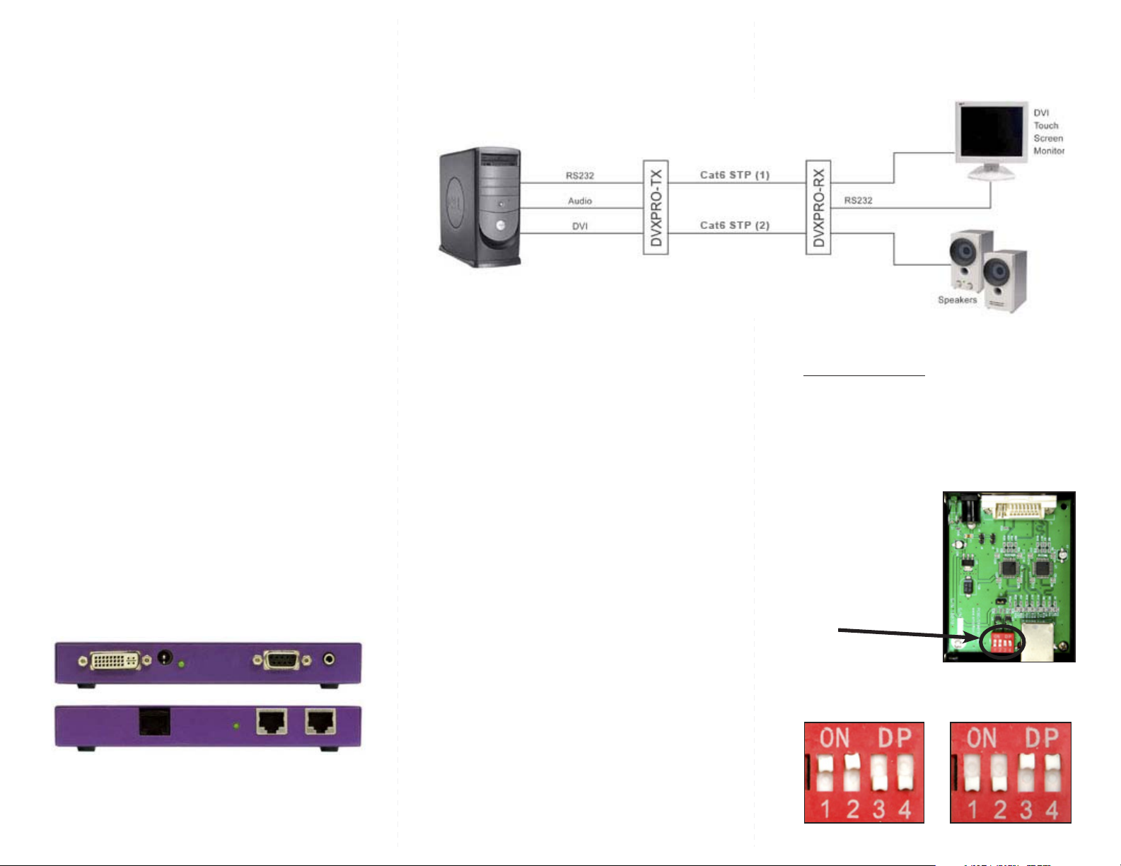
Setting the DDC
Optional DDC Pass-Through
DDC provides plug-and-play capability to your
If you would like the computer to read EDID
displays. When you plug a display into your computer,
the DDC table in the display tells the computer the
information directly from your monitor instead of
optimal resolution to use. This device is capable of
the internal EEPROM in the DVXPRO, perform the
supporting two primary types of displays: PC and Mac.
following steps.
The default setting is PC.
1. Turn off computer and monitor.
To change this setting,
rst remove the top cover
2. Disconnect power adapters from transmitter
from the TRANSMITTER
and receiver.
by removing the four side
3. Remove screws on the sides of the transmitter.
screws. Next, locate the
4. Lift the top off of the chassis
DIP switches near the rear
5. Locate headers labeled J12 and J13.
of the device next to the
Data Port (RJ45 Ethernet
Port).
J13 J12
6. Reconfigure the jumpers as shown.
For PC, congure the
7. Replace chassis top and screws.
switches as shown below:
8. Connect a second shielded Cat 6 STP cable
between port 2 on the transmitter and port 2 on
the receiver.
1&2 ON, 3&4 OFF 1&2 OFF, 3&4 ON
For Mac, congure the
switches as shown below:
 Loading...