

Page 1
Technical Specifications
© Copyright 2008 Smart-AVI, All Rights Reserved
DVX PLUS SPECIFICATIONS
Video Interface Single Link Range
Video Data Rate 1.65 Gbps
1920 x 1200 @ 60 Hz, Reso
Resolution
Power Supply
Input Interface DVI-D
USB Data
USB max data rate 12Mbps
USB compatibility 1.0 and 1.1
Connector Type
lution up to 1280 x 1024
min. 75H
Universal Switch mode PSU
(90-240V Input) 5VDC 1A
Type A (Transmitter)
Type B (Receiver)
Notice
The information contained in this document is
subject to change without notice. Smart-AVI makes
no warranty of any kind with regard to this material,
including but not limited to, implied warranties
of merchantability and fitness for any particular
purpose.
Smart-AVI will not be liable for errors contained
herein or for incidental or consequential damages
in connection with the furnishing, performance or
use of this material.
No part of this document may be photocopied,
reproduced or translated into another language
with
out prior written consent from Smart-AVI.
For the complete manual, visit www.smartavi.com.
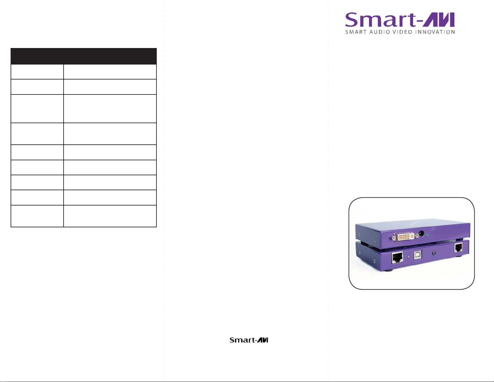
User Manual
DVX Plus
2840 N. Naomi Ave.
Burbank, California 91504
Phone: (818) 565-0011
Facsimile: (818) 565-0020
DVI-D and USB extension
via Twisted Pair
www.smartavi.com
Page 2
Introduction
DVX Plus extends Universal Serial Bus (USB 1.1) and
Digital Visual Interface (DVI-D) signals via common twisted pair cable. Using a unique method of
transparent data transfer, the system allows a USB
peripheral and a DVI display to be located up to 275
feet from the CPU.
Features
Extends USB and DVI-D signals up to 275ft from •
the computer.
Uses easy to install, inexpensive twisted pair •
cable.
Data recovery for digital video.•
Supports 1920x1200 digital video resolution.•
Fully compliant with USB 1.1 specifications.•
Supports 1.5 and 12 Mbps data rates.•
Compatible with all operating systems.•
External power adapter for transmitter and re-•
ceiver unit.
Fully transparent (does not use any emulation).•
Plug and play.•
DVX Plus Package Content
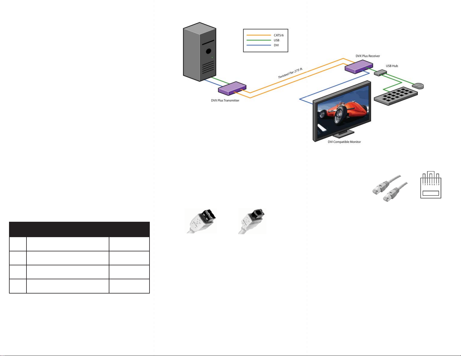
Installation Diagram
Connecting The Transmitter
Connect the transmitter to the host using an A-B 1.
USB cable.
Connect the transmitter to the host DVI-D using 2.
male to male DVI cable.
The A side of the USB connector would go to the 3.
computer host and the B side would be connected
to the transmitter.
Check that power LED is lit. The TX/RX LED should 4.
not be flashing at this time.
In the back of the unit connect the CAT5 cable that 5.
will connect to the receiver (DVXU-RX).
A
B
Preparing & Connecting System CAT5 Cable
Following is the wiring standard for terminating CAT 5 cable
using RJ-45 connector:
Pair 1 Pins 1 & 2
Pair 2 Pins 3 & 6
Pair 3 Pins 4 & 5
Pair 4 Pins 7 & 8
Connectors: RJ-45
Capacitance: 14 pf/ft (46.2 pf/m)
Conductor Gauge: 24 AWG
Impedance: 100 +/- 15 ohms
4 - Pair
Qty Items Part No.
1 DVX Plus Transmitter unit DVXU-TX
1 DVX Plus Receiver unit DVXU-RX
2 5 volt dc power supply PS-5D1A-US
Connecting The Receiver
Connect the receiver to the peripheral device using 1.
A-B USB cable. In this case the A side of the connector will go to the receiver unit and the B side of the
connector will go the peripheral. Use a USB Hub if
needed.
Connect the receiver unit to the monitor.2.
Join the DVX Plus units using shielded cable for 3.
DVI-D and standard CAT5/6 UTP cable for USB.
Once connected check that the Power LED on both
receiver and transmitter is on and the TX/RX LED is
flashing, indicating that communication exists between the two units. If receiver LED is not on, make
sure the power supply is connected.
Operating Instructions
Once installation is completed verify that the power is
present at all devices in the system. If computer was on
during the set up it might be necessary to reboot the
computer. The peripheral devices should be ready for
use.
 Loading...