

Page 1
Notice
The information contained in this document is
subject to change without notice. Smart-AVI makes
no warranty of any kind with regard to this material,
including but not limited to, implied warranties of
merchantability and fitness for any particular
purpose.
Smart-AVI will not be liable for errors contained herein
or for incidental or consequential damages in
connection with the furnishing, performance or use
of this material.
No part of this document may be photocopied,
reproduced or translated into another language with
out prior written consent from Smart-AVI.
Extend any RS232 and stereo device up
to 3000ft using a single Cat5 cable.
AR100
User Manual
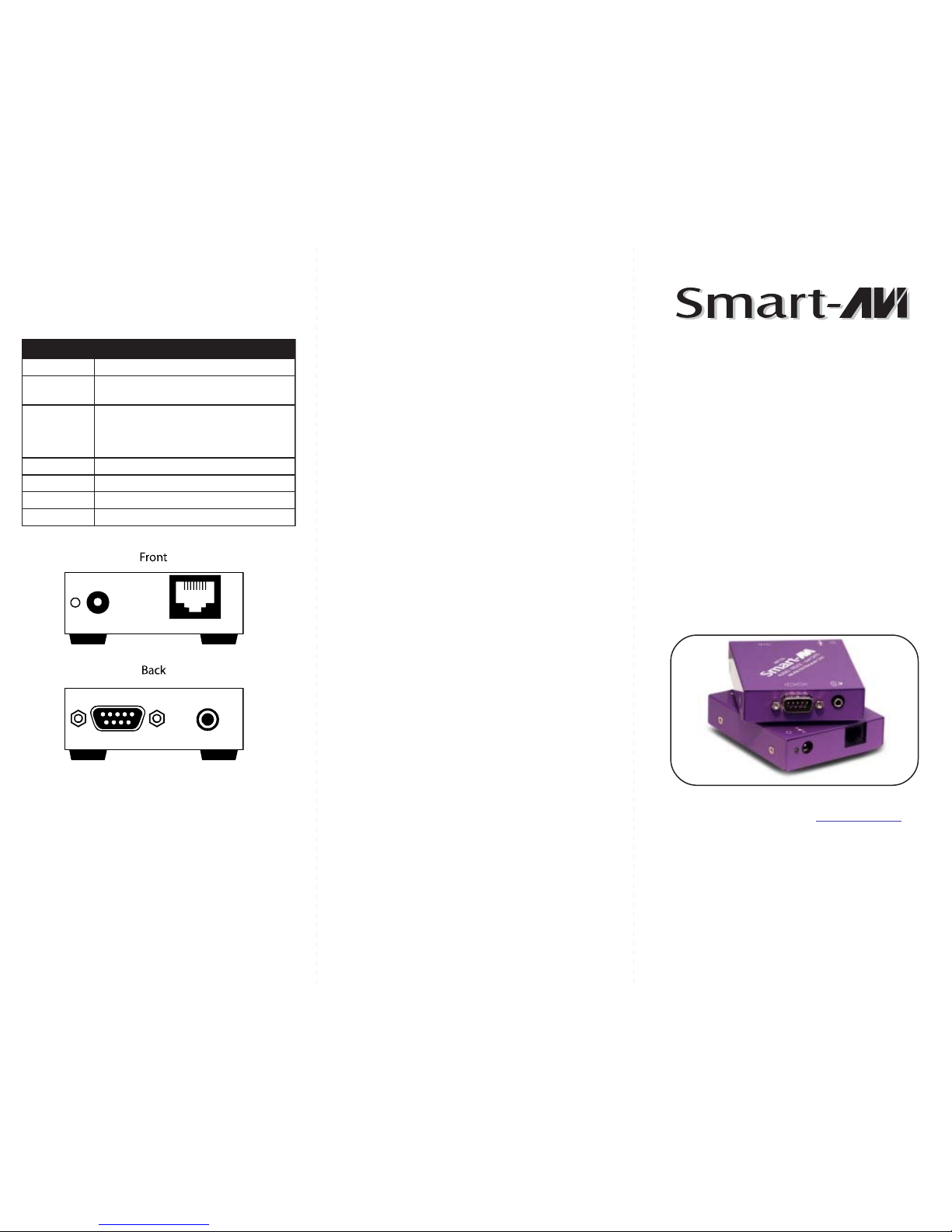
Technical Specifications
3MART !UDIO 6IDEO )NTEGRATION
3MART !UDIO 6IDEO )NTEGRATION
NOITACIFICEPS001R IICSR SIICSR SNOITACIFICEPS001RA
232SR)elaM9BD-XR()elameF9BD-XT(
locotorP
duabllaottnerapsnart,xelpudlluF
etar
oiduA
oiduAoeretSepyTlangiS
Bd0,zHM51htdiwdnaB
mhO001ecnadepmI
elameF,kcajinimmm5.3rotcennoC
5taCtf0033otpu,5taCPTU
rewoPCDV5
snoisnemiD”528.)H(x”57.2)W(x”5.3)L(
thgieWsbl02.0
Page 2
Introduction
The AR100 RS232 - Sound Cat5 extender allows
you to extend any full Duplex RS232 with any
Stereo sound up to 3000ft using a single
unshielded Cat5 cable.
Features
Unbalanced stereo line level analogue audio to
be transmitted via UTP Cat5 Hi-fidelity audio
frequency response.
Extend any touch screen up to 3000ft.
Extend any sound system up 3000ft.
Supports all protocol and baud rates.
Uses easy to install inexpensive CAT5.
Output reaches up to 3000 feet.
Compatible with line level stereo audio signals.
High ground loop immunity.
Built-in lightning, power surge and transient
protection.
Remote units come with buffered outputs.
Compact enclosure.
Optional power supply for remote unit.
Fully transparent path for all protocols and data
transfers.
t onA i s
Applications
Hotel
Cable TV remote control
Control rooms
Remote On-Digital set-top control
Sky box control extension and switcher output
Dealer rooms
Point of Sale
Remote VCR control
What’s in the box?
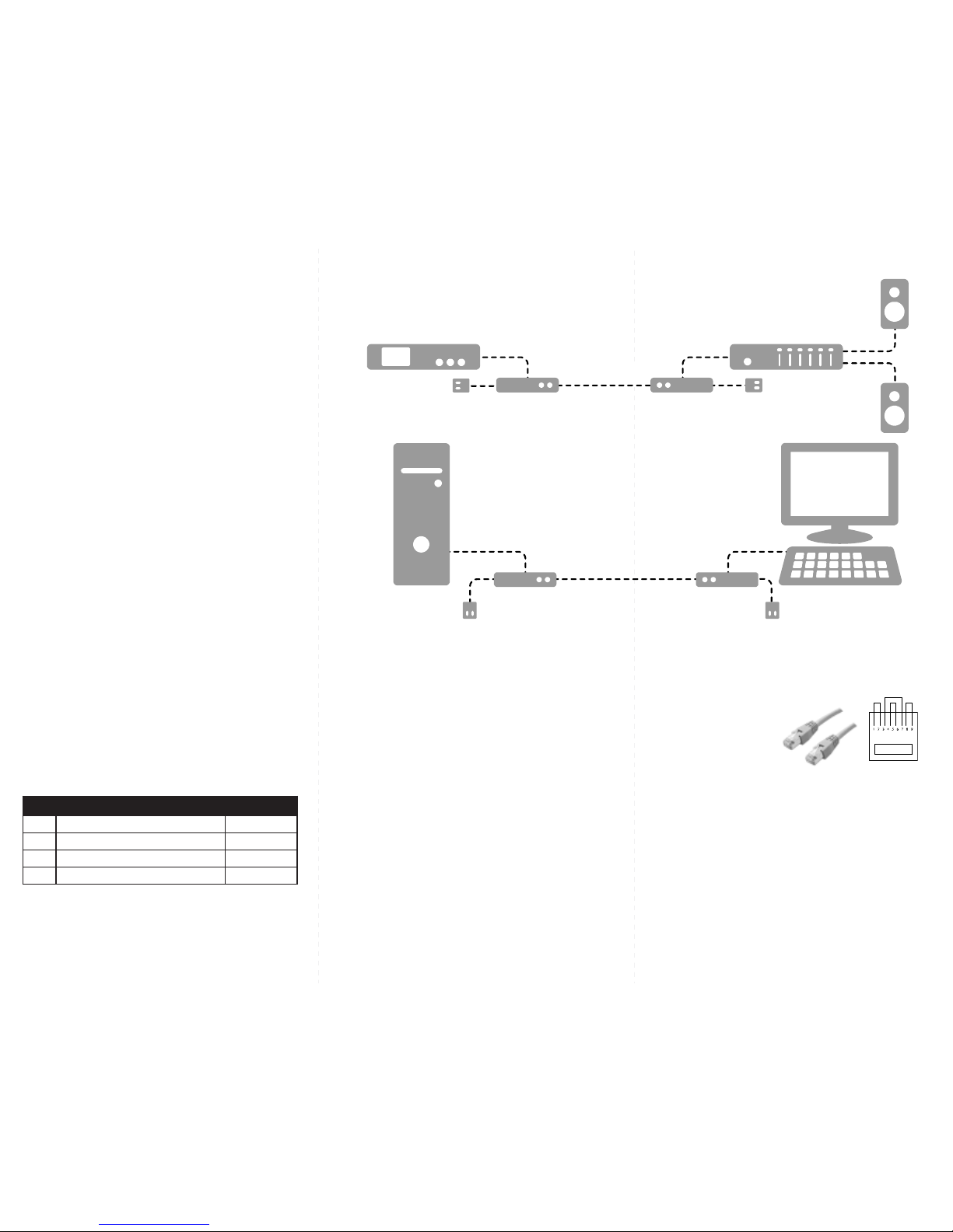
Installation Diagram
m t et
Connecting The Transmitter
1. Connect an RS232 cable and/or audio cable to the
souce unit.
2. Connect power supply to the unit. Observe LED
lighting up indicating power present
et
t eConnecting The Receiver
Connecting The Receiver
1. Connect an RS232 cable and/or audio cable to the
reveiver unit.
2. Observe LED lighting up indicating power present
P C i T Ce e A e
Preparing & Connecting System CAT5 Cable
Following is the wiring standard for terminating CAT 5
cable using RJ-45 connector:
Pair 1 Pins 1 & 2
Pair 2 Pins 3 & 6
Pair 3 Pins 4 & 5
Pair 4 Pins 7 & 8
C e
Connectors: RJ-45
C p na
Capacitance: 14 pf/ft (46.2 pf/m)
C en t G
C n t G eConductor Gauge:
Conductor Gauge: 24 AWG
Im da
Impedance: 100 +/- 15 ohms
4 - Pair
netnoCegakcaP001R kcP kcP tnetnoCegakcaP001RA
tytQmett st smetIoNtra NN .oNtraP
1tinurettimsnarT001RA001XT-RA
1tinurevieceR001RA001XR-RA
2ylppusrewopcdtlov5SU-A1D5-SP
Amplifier
AR TX100
AR TX100
AR RX100
AR RX100
CAT5 Cable
CAT5 Cable
Sound Source
Speaker
Speaker
Server Dump Terminal
5V 5V
5V 5V
 Loading...