


SmartASIC, Inc.
查询SD1010供应商
SD1010
DATA SHEET
SD1010
Dual-Interface XGA TFT
LCD Display Controller
November 1999
November, 1999 SmartASIC Confidential 1
Revision B

SmartASIC, Inc. SD1010
SD1010 DATA SHEET
DAT-SD1010-1199-B
November 1999
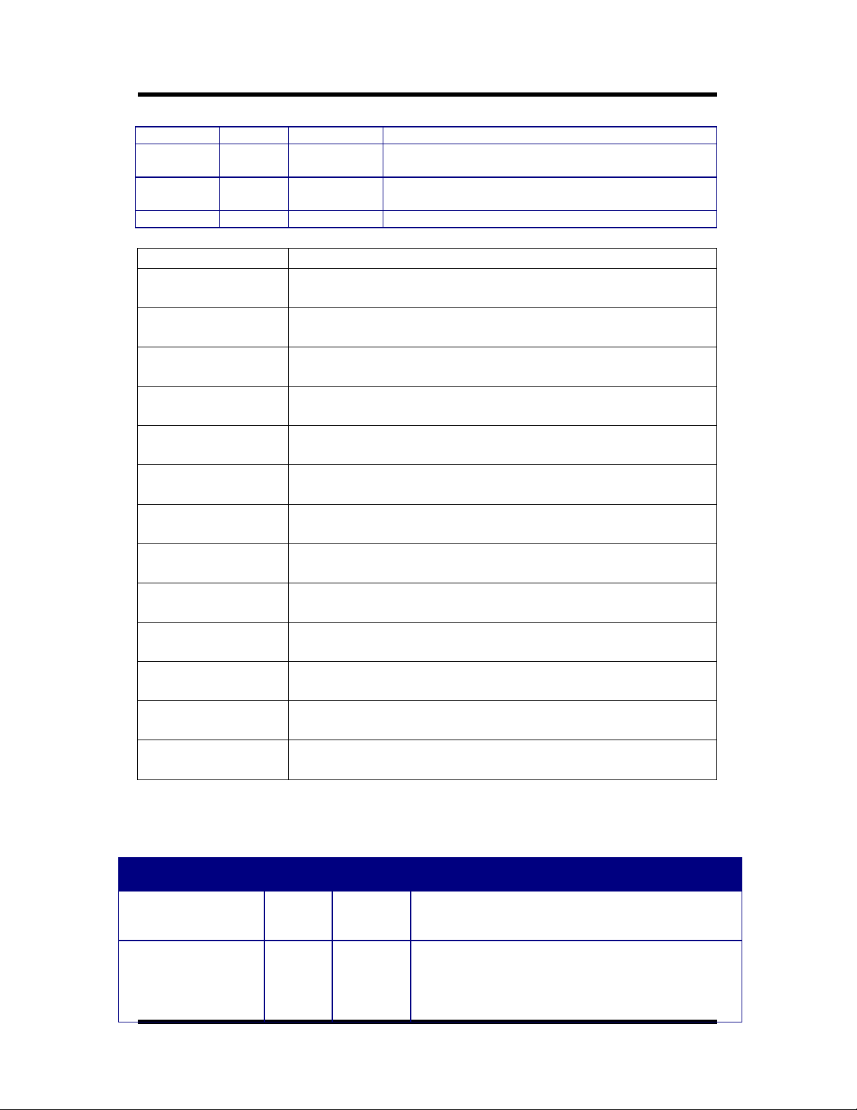
Document Revisions Date
DAT-SD1010-1099-A SD1010 Data Sheet - A October 1999
DAT-SD1010-1199-B SD1010 Data Sheet - B November 1999
Copyright 1999, SmartASIC, Inc. All Right Reserved
SmartASIC, Inc. reserves the right to change or modify the information contained herein
without notice. It is the customer’s responsibility to ensure he/she has the most recent
revision of the user guide. SmartASIC, Inc. makes no warranty for the use of its products
and bears no responsibility for any error or omissions, which may appear in this document.
November, 1999 SmartASIC Confidential 2
Revision B

SmartASIC, Inc.
1. OVERVIEW
The SD1010 is enhanced version of the SD1000 chip. It is an IC designed for dualinterface XGA TFT LCD monitors. A dual-interface LCD monitor takes analog or
digital RGB signals from a graphic card of a personal computer, the exact same input
interface as a conventional CRT monitor. This feature makes a dual-interface LCD
monitor a true replacement for a conventional CRT monitor.
The analog input RGB signals are first sampled by six channels of 8-bit A/D
converters, and the 48-bit RGB data are then fed into the SD1010. For digital
interface, the input data are first received by a TMDS receiver, and the 24/48 bit RGB
output data of TMDS receiver are then fed into the SD1010. The SD1010 is capable
of performing automatic detection of the display resolution and timing of input signals
generated from various PC graphic cards. No special driver is required for the timing
detection, nor any manual adjustment. The SD1010 then automatically scales the
input image to fill the full screen of the LCD monitor. The SD1010 can interface with
TFT LCD panels from various manufacturers by generating either 24-bit or 48-bit
RGB signal to the LCD panel based upon the timing parameters saved in the
EEPROM.
SD1010
The SD1010 implements four advanced display technologies:
1. Advanced mode detection and auto-calibration without any external CPU assist
2. Advanced programmable interpolation algorithm
3. Stand-alone mode support, and
4. Advanced true color support with both dithering and frame modulation.
The SD1010 also provides distinguished system features to the TFT LCD monitor
solution. The first one is “plug-and-play”, and the second one is “cost-effective
system solution”. To be truly plug-and-display, the SD1010 performs automatic input
mode detection and auto phase calibration, so the LCD monitor can ensure that the
A/D converters’ sample clock is precisely synchronized with the input video data, and
to preserve the highest image bandwidth for the highest image quality. Furthermore,
the SD1010 can generate output video even when the input signal is beyond the
specifications or no input signal is fed.
For “cost-effective system solution”, the SD1010 implements many system support
features such as OSD mixer, error status indicators, 2-wire serial interface for both
EEPROM and host CPU interface, and low-cost IC package. Another important
contributing factor is that the SD1010 does not require external frame buffer memory
for the automatic image scaling and synchronization.
Figure 1 shows the block diagram of the SD1010 as well as the connections of
important system components around the SD1010.
November, 1999 SmartASIC Confidential 3
Revision B

SmartASIC, Inc. SD1010
Figure 1: SD1010 Functional Block Diagram
ADC
Phase
Control
Input
PLL
Input Mode
Detection
&
Auto
Calibration
Write
Control
CPU
Interface
CPU
Buffer
Memory
Read
Control
Output
PLL
Scaling
Interpolation
Dithering
E2ROM
Interface
E2PROM
OSD
Mixer
TFT LCD
Monitor
November, 1999 SmartASIC Confidential 4
Revision B

SmartASIC, Inc. SD1010
SmartASIC
2. PIN DESCRIPTION
Figure 2: SD1010 package diagram
120 81
121
160
1 40
SD1010
80
41
November, 1999 SmartASIC Confidential 5
Revision B

SmartASIC, Inc. SD1010
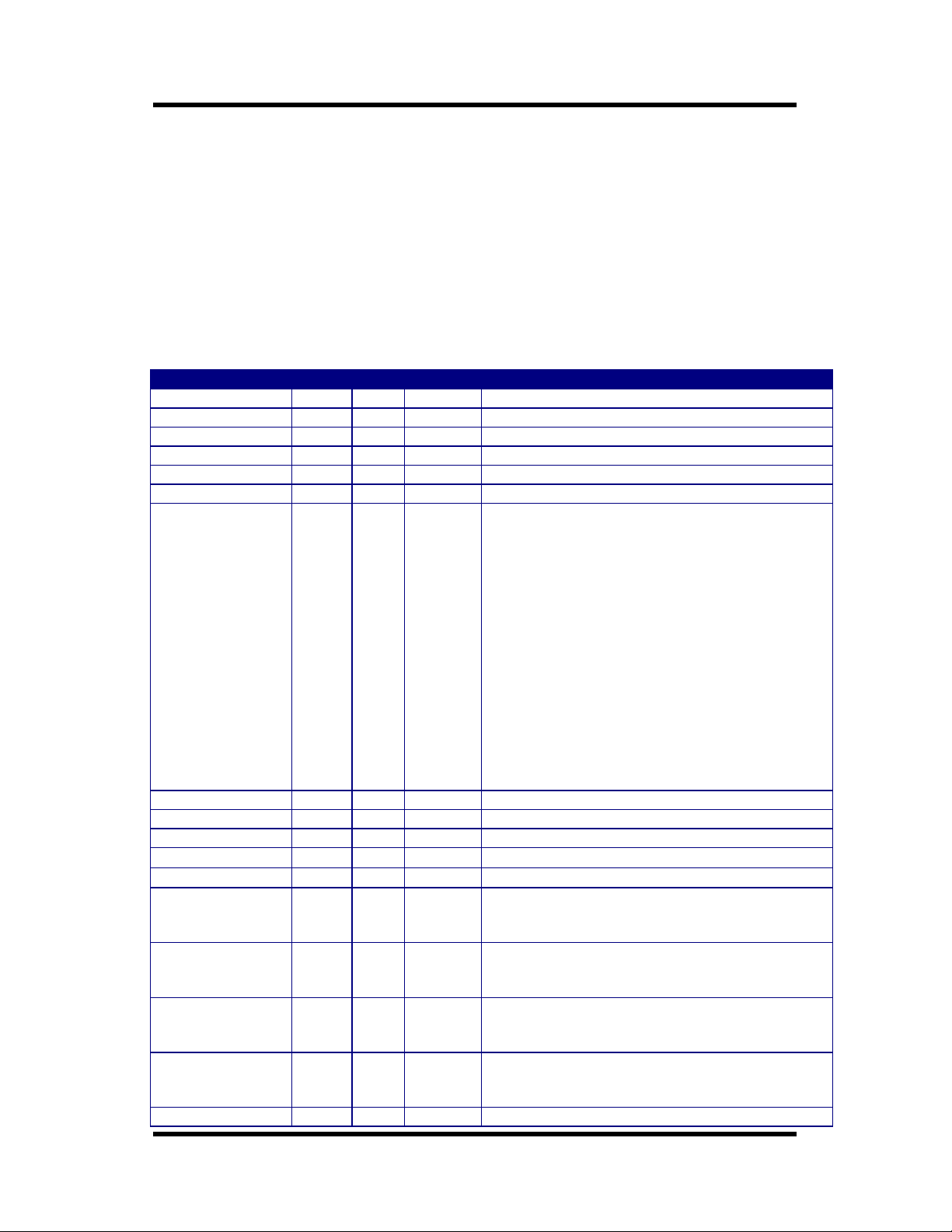
Table 1: SD1010 pin description (sorted by pin number)
Symbol PIN Number I/O Description
B_IN10 1 I Channel B Data Input Color Blue (LSB)
B_IN11 2 I Channel B Data Input Color Blue
B_IN12 3 I Channel B Data Input Color Blue
B_IN13 4 I Channel B Data Input Color Blue
DATA_SEL 5 I Indicate Channel A or Channel B contains valid input
data:
1: data in Channel A is valid
0: data in Channel B is valid
B_IN14 6 I Channel B Data Input Color Blue
B_IN15 7 I Channel B Data Input Color Blue
B_IN16 8 I Channel B Data Input Color Blue
B_IN17 9 I Channel B Data Input Color Blue (MSB)
ROM_SCL 10 O SCL in I2C for EEPROM interface
ROM_SDA 11 I/O SDA in I2C for EEPROM interface
GND 12 Ground
CPU_SCL 13 I SCL in I2C for CPU interface
CPU_SDA 14 I/O SDA in I2C for CPU interface
PWM_CTL 15 O PWM control signal (Detail description in PWM
Operation Section)
CLK_1M 16 I Free Running Clock (default: 1MHz)
VDD 17 Power Supply
CLK_1M_O 18 O Feedback of free Running Clock
RESET_B 19 I System Reset ( active LOW)
R_OSD 20 I OSD Color Red
G_OSD 21 I OSD Color Green
B_OSD 22 I OSD Color Blue
EN_OSD 23 I OSD Mixer Enable
=0, No OSD output
=1,R_OUT[7:0]= {R_OSD repeat 8 times}
G_OUT[7:0]= {G_OSD repeat 8 times }
B_OUT[7:0]= {B_OSD repeat 8 times }
SCAN_EN 24 I Manufacturing test pin (NC)
TEST_EN 25 I Manufacturing test pin (NC)
VCLK01 26 I Input Clock 1
FCLK0 27 O Input PLL Feedback Clock
VCLK00 28 I Input Clock 0
FCLK1 29 O Output PLL Feedback Clock
VCLK1 30 I Output PLL Output Clock
HSYNC_O 31 O Output HSYNC (the polarity is programmable through
CPU, default is active low)
VSYNC_O 32 O Output VSYNC (the polarity is programmable through
CPU, default is active low)
DCLK_OUT 33 O Output Clock to Control Panel (the polarity is
programmable through CPU)
DE_OUT 34 O Output Display Enable for Panel (the polarity is
programmable through CPU, default is active HIGH)
GND 35 Ground
VDD 36 Power Supply
R_OUT0_E 37 O Output Color Red Even Pixel (left pixel)
November, 1999 SmartASIC Confidential 6
Revision B

SmartASIC, Inc. SD1010
R_OUT1_E 38 O Output Color Red Even Pixel (left pixel)
R_OUT2_E 39 O Output Color Red Even Pixel (left pixel)
R_OUT3_E 40 O Output Color Red Even Pixel (left pixel)
HSYNC_X 41 O Default HSYNC generated by ASIC (active LOW)
VSYNC_X 42 O Default VSYNC generated by ASIC (active LOW)
GND 43 Ground
R_OUT4_E 44 O Output Color Red Even Pixel (left pixel)
VDD 45 Power Supply
VDD 46 Power Supply
R_OUT5_E 47 O Output Color Red Even Pixel (left pixel)
GND 48 Ground
R_OUT6_E 49 O Output Color Red Even Pixel (left pixel)
R_OUT7_E 50 O Output Color Red Even Pixel (left pixel)
GND 51 Ground
R_OUT0_O 52 O Output Color Red Odd Pixel (right pixel)
R_OUT1_O 53 O Output Color Red Odd Pixel (right pixel)
R_OUT2_O 54 O Output Color Red Odd Pixel (right pixel)
R_OUT3_O 55 O Output Color Red Odd Pixel (right pixel)
VDD 56 Power Supply
R_OUT4_O 57 O Output Color Red Odd Pixel (right pixel)
R_OUT5_O 58 O Output Color Red Odd Pixel (right pixel)
R_OUT6_O 59 O Output Color Red Odd Pixel (right pixel)
R_OUT7_O 60 O Output Color Red Odd Pixel (right pixel)
GND 61 Ground
G_OUT0_E 62 O Output Color Green Even Pixel (left pixel)
G_OUT1_E 63 O Output Color Green Even Pixel (left pixel)
G_OUT2_E 64 O Output Color Green Even Pixel (left pixel)
G_OUT3_E 65 O Output Color Green Even Pixel (left pixel)
G_OUT4_E 66 O Output Color Green Even Pixel (left pixel)
VDD 67 Power Supply
G_OUT5_E 68 O Output Color Green Even Pixel (left pixel)
G_OUT6_E 69 O Output Color Green Even Pixel (left pixel)
G_OUT7_E 70 O Output Color Green Even Pixel (left pixel)
GND 71 Ground
GND 72 Ground
G_OUT0_O 73 O Output Color Green Odd Pixel (right pixel)
G_OUT1_O 74 O Output Color Green Odd Pixel (right pixel)
G_OUT2_O 75 O Output Color Green Odd Pixel (right pixel)
G_OUT3_O 76 O Output Color Green Odd Pixel (right pixel)
VDD 77 Power Supply
G_OUT4_O 78 O Output Color Green Odd Pixel (right pixel)
G_OUT5_O 79 O Output Color Green Odd Pixel (right pixel)
G_OUT6_O 80 O Output Color Green Odd Pixel (right pixel)
G_OUT7_O 81 O Output Color Green Odd Pixel (right pixel)
GND 82 Ground
GND 83 Ground
B_OUT0_E 84 O Output Color Blue Even Pixel (left pixel)
B_OUT1_E 85 O Output Color Blue Even Pixel (left pixel)
B_OUT2_E 86 O Output Color Blue Even Pixel (left pixel)
B_OUT3_E 87 O Output Color Blue Even Pixel (left pixel)
B_OUT4_E 88 O Output Color Blue Even Pixel (left pixel)
B_OUT5_E 89 O Output Color Blue Even Pixel (left pixel)
November, 1999 SmartASIC Confidential 7
Revision B

SmartASIC, Inc. SD1010
B_OUT6_E 90 O Output Color Blue Even Pixel (left pixel)
VDD 91 Power Supply
VDD 92 Power Supply
B_OUT7_E 93 O Output Color Blue Even Pixel (left pixel)
GND 94 Ground
B_OUT0_O 95 O Output Color Blue Odd Pixel (right pixel)
B_OUT1_O 96 O Output Color Blue Odd Pixel (right pixel)
B_OUT2_O 97 O Output Color Blue Odd Pixel (right pixel)
B_OUT3_O 98 O Output Color Blue Odd Pixel (right pixel)
VDD 99 Power Supply
B_OUT4_O 100 O Output Color Blue Odd Pixel (right pixel)
B_OUT5_O 101 O Output Color Blue Odd Pixel (right pixel)
B_OUT6_O 102 O Output Color Blue Odd Pixel (right pixel)
B_OUT7_O 103 O Output Color Blue Odd Pixel (right pixel)
GND 104 Ground
R_IN00 105 I Channel A Data Input Color Red (LSB)
R_IN01 106 I Channel A Data Input Color Red
R_IN02 107 I Channel A Data Input Color Red
R_IN03 108 I Channel A Data Input Color Red
VDD 109 Power Supply
R_IN04 110 I Channel A Data Input Color Red
R_IN05 111 I Channel A Data Input Color Red
R_IN06 112 I Channel A Data Input Color Red
R_IN07 113 I Channel A Data Input Color Red (MSB)
R_IN10 114 I Channel B Data Input Color Red (LSB)
R_IN11 115 I Channel B Data Input Color Red
GND 116 Ground
R_IN12 117 I Channel B Data Input Color Red
R_IN13 118 I Channel B Data Input Color Red
VDD 119 Power Supply
R_IN14 120 I Channel B Data Input Color Red
R_IN15 121 I Channel B Data Input Color Red
R_IN16 122 I Channel B Data Input Color Red
R_IN17 123 I Channel B Data Input Color Red (MSB)
GND 124 Ground
G_IN00 125 I Channel A Data Input Color Green (LSB)
G_IN01 126 I Channel A Data Input Color Green
G_IN02 127 I Channel A Data Input Color Green
G_IN03 128 I Channel A Data Input Color Green
VDD 129 Power Supply
G_IN04 130 I Channel A Data Input Color Green
G_IN05 131 I Channel A Data Input Color Green
ADC_CLK0 132 O Sample Clock for ADC 0
G_IN06 133 I Channel A Data Input Color Green
G_IN07 134 I Channel A Data Input Color Green (MSB)
GND 135 Ground
G_IN10 136 I Channel B Data Input Color Green (LSB)
G_IN11 137 I Channel B Data Input Color Green
ADC_CLK1 138 O Sample Clock for ADC 1
G_IN12 139 I Channel B Data Input Color Green
G_IN13 140 I Channel B Data Input Color Green
VDD 141 Power Supply
November, 1999 SmartASIC Confidential 8
Revision B

SmartASIC, Inc. SD1010
G_IN14 142 I Channel B Data Input Color Green
G_IN15 143 I Channel B Data Input Color Green
G_IN16 144 I Channel B Data Input Color Green
G_IN17 145 I Channel B Data Input Color Green (MSB)
GND 146 Ground
B_IN00 147 I Channel A Data Input Color Blue (LSB)
B_IN01 148 I Channel A Data Input Color Blue
B_IN02 149 I Channel A Data Input Color Blue
VDD 150 Power Supply
B_IN03 151 I Channel A Data Input Color Blue
B_IN04 152 I Channel A Data Input Color Blue
B_IN05 153 I Channel A Data Input Color Blue
B_IN06 154 I Channel A Data Input Color Blue
B_IN07 155 I Channel A Data Input Color Blue (MSB)
GND 156 Ground
HSYNC_I 157 I Input HSYNC (any polarity)
VSYNC_I 158 I Input VSYNC (any polarity)
DE_IN 159 I DE input for digital interface
VDD 160 Power Supply
November, 1999 SmartASIC Confidential 9
Revision B

SmartASIC, Inc. SD1010
Table 2: SD1010 pin description (sorted by function)
Symbol PIN Number I/O Description
R_IN00 105 I Channel A Data Input Color Red (LSB)
R_IN01 106 I Channel A Data Input Color Red
R_IN02 107 I Channel A Data Input Color Red
R_IN03 108 I Channel A Data Input Color Red
R_IN04 110 I Channel A Data Input Color Red
R_IN05 111 I Channel A Data Input Color Red
R_IN06 112 I Channel A Data Input Color Red
R_IN07 113 I Channel A Data Input Color Red (MSB)
R_IN10 114 I Channel B Data Input Color Red (LSB)
R_IN11 115 I Channel B Data Input Color Red
R_IN12 117 I Channel B Data Input Color Red
R_IN13 118 I Channel B Data Input Color Red
R_IN14 120 I Channel B Data Input Color Red
R_IN15 121 I Channel B Data Input Color Red
R_IN16 122 I Channel B Data Input Color Red
R_IN17 123 I Channel B Data Input Color Red (MSB)
G_IN00 125 I Channel A Data Input Color Green (LSB)
G_IN01 126 I Channel A Data Input Color Green
G_IN02 127 I Channel A Data Input Color Green
G_IN03 128 I Channel A Data Input Color Green
G_IN04 130 I Channel A Data Input Color Green
G_IN05 131 I Channel A Data Input Color Green
G_IN06 133 I Channel A Data Input Color Green
G_IN07 134 I Channel A Data Input Color Green (MSB)
G_IN10 136 I Channel B Data Input Color Green (LSB)
G_IN11 137 I Channel B Data Input Color Green
G_IN12 139 I Channel B Data Input Color Green
G_IN13 140 I Channel B Data Input Color Green
G_IN14 142 I Channel B Data Input Color Green
G_IN15 143 I Channel B Data Input Color Green
G_IN16 144 I Channel B Data Input Color Green
G_IN17 145 I Channel B Data Input Color Green (MSB)
B_IN00 147 I Channel A Data Input Color Blue (LSB)
B_IN01 148 I Channel A Data Input Color Blue
B_IN02 149 I Channel A Data Input Color Blue
B_IN03 151 I Channel A Data Input Color Blue
B_IN04 152 I Channel A Data Input Color Blue
B_IN05 153 I Channel A Data Input Color Blue
B_IN06 154 I Channel A Data Input Color Blue
B_IN07 155 I Channel A Data Input Color Blue (MSB)
B_IN10 1 I Channel B Data Input Color Blue (LSB)
B_IN11 2 I Channel B Data Input Color Blue
B_IN12 3 I Channel B Data Input Color Blue
B_IN13 4 I Channel B Data Input Color Blue
B_IN14 6 I Channel B Data Input Color Blue
B_IN15 7 I Channel B Data Input Color Blue
B_IN16 8 I Channel B Data Input Color Blue
B_IN17 9 I Channel B Data Input Color Blue (MSB)
November, 1999 SmartASIC Confidential 10
Revision B

SmartASIC, Inc. SD1010
DATA_SEL 5 I Indicate Channel A or Channel B contains valid input
data:
1: data in Channel A is valid
0: data in Channel B is valid
HSYNC_I 157 I Input HSYNC (any polarity)
VSYNC_I 158 I Input VSYNC (any polarity)
DE_IN 159 I DE input for digital interface
ADC_CLK0 132 O Sample Clock for ADC 0
ADC_CLK1 138 O Sample Clock for ADC 1
R_OUT0_E 37 O Output Color Red Even Pixel (left pixel)
R_OUT1_E 38 O Output Color Red Even Pixel (left pixel)
R_OUT2_E 39 O Output Color Red Even Pixel (left pixel)
R_OUT3_E 40 O Output Color Red Even Pixel (left pixel)
R_OUT4_E 44 O Output Color Red Even Pixel (left pixel)
R_OUT5_E 47 O Output Color Red Even Pixel (left pixel)
R_OUT6_E 49 O Output Color Red Even Pixel (left pixel)
R_OUT7_E 50 O Output Color Red Even Pixel (left pixel)
R_OUT0_O 52 O Output Color Red Odd Pixel (right pixel)
R_OUT1_O 53 O Output Color Red Odd Pixel (right pixel)
R_OUT2_O 54 O Output Color Red Odd Pixel (right pixel)
R_OUT3_O 55 O Output Color Red Odd Pixel (right pixel)
R_OUT4_O 57 O Output Color Red Odd Pixel (right pixel)
R_OUT5_O 58 O Output Color Red Odd Pixel (right pixel)
R_OUT6_O 59 O Output Color Red Odd Pixel (right pixel)
R_OUT7_O 60 O Output Color Red Odd Pixel (right pixel)
G_OUT0_E 62 O Output Color Green Even Pixel (left pixel)
G_OUT1_E 63 O Output Color Green Even Pixel (left pixel)
G_OUT2_E 64 O Output Color Green Even Pixel (left pixel)
G_OUT3_E 65 O Output Color Green Even Pixel (left pixel)
G_OUT4_E 66 O Output Color Green Even Pixel (left pixel)
G_OUT5_E 68 O Output Color Green Even Pixel (left pixel)
G_OUT6_E 69 O Output Color Green Even Pixel (left pixel)
G_OUT7_E 70 O Output Color Green Even Pixel (left pixel)
G_OUT0_O 73 O Output Color Green Odd Pixel (right pixel)
G_OUT1_O 74 O Output Color Green Odd Pixel (right pixel)
G_OUT2_O 75 O Output Color Green Odd Pixel (right pixel)
G_OUT3_O 76 O Output Color Green Odd Pixel (right pixel)
G_OUT4_O 78 O Output Color Green Odd Pixel (right pixel)
G_OUT5_O 79 O Output Color Green Odd Pixel (right pixel)
G_OUT6_O 80 O Output Color Green Odd Pixel (right pixel)
G_OUT7_O 81 O Output Color Green Odd Pixel (right pixel)
B_OUT0_E 84 O Output Color Blue Even Pixel (left pixel)
B_OUT1_E 85 O Output Color Blue Even Pixel (left pixel)
B_OUT2_E 86 O Output Color Blue Even Pixel (left pixel)
B_OUT3_E 87 O Output Color Blue Even Pixel (left pixel)
B_OUT4_E 88 O Output Color Blue Even Pixel (left pixel)
November, 1999 SmartASIC Confidential 11
Revision B

SmartASIC, Inc. SD1010
B_OUT5_E 89 O Output Color Blue Even Pixel (left pixel)
B_OUT6_E 90 O Output Color Blue Even Pixel (left pixel)
B_OUT7_E 93 O Output Color Blue Even Pixel (left pixel)
B_OUT0_O 95 O Output Color Blue Odd Pixel (right pixel)
B_OUT1_O 96 O Output Color Blue Odd Pixel (right pixel)
B_OUT2_O 97 O Output Color Blue Odd Pixel (right pixel)
B_OUT3_O 98 O Output Color Blue Odd Pixel (right pixel)
B_OUT4_O 100 O Output Color Blue Odd Pixel (right pixel)
B_OUT5_O 101 O Output Color Blue Odd Pixel (right pixel)
B_OUT6_O 102 O Output Color Blue Odd Pixel (right pixel)
B_OUT7_O 103 O Output Color Blue Odd Pixel (right pixel)
HSYNC_O 31 O Output HSYNC (the polarity is programmable
through CPU, default is active low)
VSYNC_O 32 O Output VSYNC (the polarity is programmable
through CPU, default is active low)
DCLK_OUT 33 O Output Clock to Control Panel (the polarity is
programmable through CPU)
DE_OUT 34 O Output Display Enable for Panel (the polarity is
programmable through CPU, default is active HIGH)
VCLK01 26 I Input Clock 1
FCLK0 27 O Input PLL Feedback Clock
VCLK00 28 I Input Clock 0
FCLK1 29 O Output PLL Feedback Clock
VCLK1 30 I Output PLL Output Clock
ROM_SCL 10 O SCL in I2C for EEPROM interface
ROM_SDA 11 I/O SDA in I2C for EEPROM interface
CPU_SCL 13 I SCL in I2C for CPU interface
CPU_SDA 14 I/O SDA in I2C for CPU interface
PWM_CTL 15 O PWM control signal (Detail description in PWM
Operation Section)
CLK_1M 16 I Free Running Clock (default: 1MHz)
CLK_1M_O 18 O Feedback of free Running Clock
RESET_B 19 I System Reset ( active LOW)
HSYNC_X 41 O Default HSYNC generated by ASIC (active LOW)
VSYNC_X 42 O Default VSYNC generated by ASIC (active LOW)
R_OSD 20 I OSD Color Red
G_OSD 21 I OSD Color Green
B_OSD 22 I OSD Color Blue
EN_OSD 23 I OSD Mixer Enable
=0, No OSD output
=1,R_OUT[7:0]= {R_OSD repeat 8 times}
G_OUT[7:0]= {G_OSD repeat 8 times }
B_OUT[7:0]= {B_OSD repeat 8 times }
November, 1999 SmartASIC Confidential 12
Revision B

SmartASIC, Inc. SD1010
SCAN_EN 24 I Manufacturing test pin (NC)
TEST_EN 25 I Manufacturing test pin (NC)
VDD 17 Power Supply
VDD 36 Power Supply
VDD 45 Power Supply
VDD 46 Power Supply
VDD 56 Power Supply
VDD 67 Power Supply
VDD 77 Power Supply
VDD 91 Power Supply
VDD 92 Power Supply
VDD 99 Power Supply
VDD 109 Power Supply
VDD 119 Power Supply
VDD 129 Power Supply
VDD 141 Power Supply
VDD 150 Power Supply
VDD 160 Power Supply
GND 12 Ground
GND 35 Ground
GND 43 Ground
GND 48 Ground
GND 51 Ground
GND 61 Ground
GND 71 Ground
GND 72 Ground
GND 82 Ground
GND 83 Ground
GND 94 Ground
GND 104 Ground
GND 116 Ground
GND 124 Ground
GND 135 Ground
GND 146 Ground
GND 156 Ground
November, 1999 SmartASIC Confidential 13
Revision B

SmartASIC, Inc. SD1010
3. FUNCTIONAL DESCRIPTION
The SD1010 has the following major function blocks:
1. Input mode detection and auto calibration block
2. Buffer memory and read/write control block
3. Image scaling, interpolation and dithering block
4. OSD mixer and LCD interface block
5. EEPROM interface block
6. CPU interface block
The following sections will describe the functionality of these blocks.
3.1. Input mode detection & auto calibration block
3.1.1. Supported input modes
SD1010 can handle up to 14 different input modes. For SD1010, an input mode is
defined by its horizontal resolution with its vertical resolution. The input modes with
the same horizontal and vertical resolution but with different frame rates are still
considered as one single input mode. In the default EEPROM setup, SD1010 accepts
the following seven input video modes:
1. 640 x 350
2. 640 x 400
3. 720 x 400
4. 640 x 480 (VGA)
5. 800 x 600 (SVGA)
6. 832 x 624 (MAC)
7. 1024 x 768 (XGA)
Users can easily change the definitions of the acceptable input modes by adjusting the
values in the appropriate EEPROM entries. There is no frame rate restriction on the
input modes. However, since the output signal is synchronized with the input signal at
the same refresh rate, the input refresh rate has to be within the acceptable range of
the LCD panel.
The user-defined video modes can be defined by storing appropriate timing
information in the EEPROM. Detail definitions of the EEPROM entries are described
in Section 3.5.2.
November, 1999 SmartASIC Confidential 14
Revision B

SmartASIC, Inc. SD1010
3.1.2. Input mode detection and frequency detection
The SD1010 can automatically detect the mode of the input signal without any user
adjustment or driver running on the PC host or external CPU. This block
automatically detects polarity of input synchronization and the sizes of back porch,
valid data window and the synchronization pulse width in both vertical and horizontal
directions. The size information is then used not only to decide the input resolution, to
generate the frequency divider for the input PLL, to lock the PLL output clock with
HSYNC, but also to automatically scale the image to full screen and to synchronize
the output signal with the input signal.
The detection logic is always active to automatically detect any changes to the input
mode. Users can manually change the input mode information at run time through the
CPU interface. Detailed operation of the CPU interface is described in Section 3.6.
“CPU Interface”.
Mode detection and frequency detection can be independently turned ON or OFF by
the external CPU. This feature allows system customers to have better control of the
mode-detection and frequency detection process. When the detection is turned OFF,
the external CPU can change the input mode and frequency definitions.
3.1.3. Phase calibration
The SD1010 can automatically calibrate the phase of the sample clock in order to
preserve the bandwidth of the input signal and to get the best quality. The SD1010
implements a proprietary image quality function. During the auto-calibration process,
the SD1010 continues to search for the best phase to optimize the image quality.
The output image may display some jitter and blurring during the auto-calibration
process, and the image will become crisp and sharp once the optimum phase is found.
User can change the sampling clock phase value through the external CPU. Detailed
operation of the CPU interface is described in Section 3.6. “CPU Interface”.
The phase calibration process can be delayed and even disabled by the external CPU
if the system designer wants to have his/her own implementation. The phase
calibration can be independently turned ON or OFF by the external CPU. When the
calibration is turned OFF, the external CPU can change the input mode and frequency
definitions.
3.1.4. PWM operation
The SD1010 implements a unique algorithm to adjust the phase of the A/D
converter’s sampling clock. An external delay circuit is required to compliment the
SD1010 for the phase-calibration process. The SD1010 generates a Pulse-Width
Modulated (PWM) signal to the external delay circuit. The delay circuit should insert
a certain amount of time delay synchronization pulse based upon the width of the
PWM signal. A brief circuit diagram for the PWM is shown in Figure 3.
November, 1999 SmartASIC Confidential 15
Revision B

SmartASIC, Inc. SD1010
The PWM signal from the SD1010 is a periodical signal with a period that is 1023
times the period of the free-running clock connected to the pin “CLK_1M”. System
manufacturers may select any frequency for the free running clock. The default clock
frequency is 1MHz. System manufacturers also decide the unit delay for the external
delay circuit. The delay information is stored in the EEPROM. When the SD1010
wants to delay the synchronization pulse for N units of delay, it will output the PWM
with the high time equal to (N * the period of the free-running clock), and with low
time equal to (1023-N)* the period of the free-running clock. When N=1023, the
PWM signal stays high all the time, and when N=0, the PWM signal is always low.
Figure 3: SD1010 PWM circuitry block diagram
SD1010
PWM
Delay
PLL
Circuitry
Synchronization pulse
Ref_Clk
3.1.5. Free Running Clock
As described in previous section, a free-running clock is needed for the SD1010. This
clock is used for many of the SD1010’s internal operations. PWM operation is one of
them. System manufacturers can select the frequency of the free-running clock, and
the default clock frequency is 1MHz. System manufacturers can use an oscillator to
generate the free-running clock, and feed that clock directly to the pin “CLK_1M”, or
use a crystal connecting to “CLK_1M” and “CLK_1M_O”.
3.2. Buffer memory and read/write control block
The SD1010 uses internal buffer memory to store a portion of the input image for
image scaling and output synchronization. No external memory buffer is needed for
the SD1010. The write control logic ensures the input data are stored into the right
area of the buffer memory, and the read control logic is responsible to fetch the data
from the buffer memory from the correct area and at the correct timing sequence.
With the precise timing control of the write and read logic, the output image is
appropriately scaled to the full screen, and the output signal is perfectly synchronized
with the input signals.
November, 1999 SmartASIC Confidential 16
Revision B

SmartASIC, Inc. SD1010
3.3. Image scaling, interpolation and dithering block
The SD1010 supports both automatic image scaling and interpolation.
3.3.1. Image scaling
The SD1010 supports several different input modes, and the input image may have
different sizes. It is essential to support automatic image scaling so that the input
image is always displayed to the full screen regardless the input mode. The SD1010
scales the images in both horizontal and vertical directions. It calculates the correct
scaling ratio for both directions based upon the LCD panel resolution and the input
mode and timing information produced by the “Input mode detection & auto
calibration” block. The scaling ratio is re-adjusted whenever a different input mode is
detected. The ratio is then fed to the buffer memory read control logic to fetch the
image data with the right sequence and timing. Some of the image data may be read
more than once to achieve the scaling effect.
3.3.2. Image interpolation
The SD1010 supports image interpolation to achieve better image quality. A basic
image scaling algorithm replicates the input images to achieve the scaling effect. The
replication scheme usually results in a poor image quality. The SD1010 implements a
proprietary interpolation algorithm to improve the image quality. The programmable
interpolation is implemented with a 256-entry mapping table in the EEPROM to allow
system users to adjust the bi-linear interpolation parameters to control the sharpness
and smoothness quality of the image. In the default setting, the mapping table
contains a straight line of slope equal to 1, i.e. the data in entry N equal to the value
N. If the mapping table contains a line of slope equal to 2, then the output image will
be a bit sharper than the image generated by a table with the default setting. Through
an external microcontroller, users can chose among different interpolation algorithm.
3.3.3. Dithering
The SD1010 supports 16.7 million true colors for a 6-bit panel. Two dithering
algorithms are implemented and users can chose between them through the external
microcontroller. The first one is area-based dithering, and the second one is a framebased frame modulation, which also is called frame rate control. Through the external
microcontroller, users can choose among different dithering algorithms.
3.3.4. Text Enhancement
In order to generate a good picture, the SD1010 incorporate a proprietary scheme to
detect text and non-text picture. Then applying the appropriate process to improve the
text image based on the detection of incoming source. By using the text enhancement
November, 1999 SmartASIC Confidential 17
Revision B

SmartASIC, Inc. SD1010
function correctly, the text image will be looked more pleasant and near perfect after
scaled up or down. Users can achieve a preferred image by changing the settings in
“text control” register.
3.3.5. Sharpness Enhancement
No matter how many times the original image got enlarged or shrunk by the internal
interpolator. With the embedded powerful DSP arrays, SD1010 always can enhance
the overall image sharpness (edge) to different degree for the various requirements.
The sharpness can be adjusted bi-directionally which means either going sharper or
softer to certain point set by the user. It’s easy to activate the sharpness enhancement
by program “sharpness control” register.
3.4. OSD mixer and LCD interface
At the output stage, the SD1010 performs the OSD mixer function, and then generates
the 24-bit / 48-bit RGB signal to the LCD panel with the correct timing.
3.4.1. OSD mixer
In the OSD mixer block, the SD1010 mixes the normal output RGB signal with the
OSD signal. The OSD output data is generated based on the “R_OSD”, “G_OSD” and
“B_OSD” pins as well as the “OSD Intensity” data in EEPROM entry. When the
“EN_OSD” is active high, the OSD is active, and the SD1010 will send the OSD data
to the LCD panel. The OSD has 16 different color schemes based on the combinations
of the three OSD color pins and the “OSD Intensity” data. When R_OSD=1, and
OSD_Intensity=0, the SD1010 will output 128 to the output red channel, R_OUT.
When R_OSD=1 and OSD_Intensity=1, the SD1010 will output 255. The same
scheme is used for G_OSD to G_OUT and for B_OSD to B_OUT.
As part of the mixer control function, the SD1010 implements three mixing control
registers, “OSD R Weight” (38H), “OSD G Weight”(39H), and “OSD B Weight”
(3AH). The mixing equation is shown below:
R_OUT = (R_OSD) * (OSD R Weight/255) + R * (1 - OSD R Weight/255)
G_OUT = (G_OSD) * (OSD G Weight/255) + G * (1 - OSD G Weight/255)
B_OUT = (B_OSD) * (OSD B Weight/255) + B * (1 - OSD B Weight/255)
When the weight is 255, the OSD output will overlay on top of the normal output.
When the weight is 0, the OSD output is disabled.
November, 1999 SmartASIC Confidential 18
Revision B

SmartASIC, Inc. SD1010
3.4.2. LCD interface
The SD1010 support both 24- and 48-bit RGB interfaces with XGA LCD panels from
various panel manufacturers. The LCD panel resolution and timing information is
stored in the external EEPROM. The information in the EEPROM includes timing
related to the output back porch, synchronization pulse width and valid data window.
The timing information is used to generate the frequency divider for the output PLL,
to lock the PLL output clock with HSYNC for the LCD data clock, and to
synchronize the output VSYNC and input VSYNC.
3.5. EEPROM interface
As mentioned in previous sections, the external EEPROM stores crucial information
for the SD1010 internal operations. The SD1010 interfaces with the EEPROM
through a 2-wire serial interface. The suggested EEPROM device is an industry
standard serial-interface EEPROM (24x08). The 2-wire serial interface scheme is
briefly described here and a detailed description can be found in public literature.
3.5.1. 2-wire serial interface
The 2-wire serial interface uses 2 wires, SCL and SDA. The SCL is driven by the
SD1010 and used mainly as the sampling clock. The SDA is a bi-directional signal
and used mainly as a data signal. Figure 4 shows the basic bit definitions of the 2-wire
serial interface.
The 2-wire serial interface supports random and sequential read operations. Figures 5
and 6 show the data sequences for random read and sequential read operations.
November, 1999 SmartASIC Confidential 19
Revision B

SmartASIC, Inc. SD1010
DATA
DATA
DATA
Figure 4: START, STOP AND DATA Definitions in 2-wire serial interface
SDA
SCL
START STOP
CHANGE
STABLE
CHANGE
November, 1999 SmartASIC Confidential 20
Revision B

SmartASIC, Inc. SD1010
L
L
L
S
DEVICE
A
M
A
M
A
S
W
WORD
DEVICE
M
R
A
M
S
S
R
Figure 5: Data sequence for read access (both single and multiple bytes)
T
A
R
T
S
B
B
I
T
ADDRESS
[6:0]
6
R
I
C
T
K
E
S
/_
B
W
B
I
T
0
ADDRESS
[5:0]
S
B
B
I
T
7
C
K
T
T
A
O
P
R
T
S
B
B
I
T
6
ADDRESS
[6:0]
S
B
B
I
T
0
C
E
K
A
D
DATA READ
S
B
B
I
T
7
T
O
C
P
K
S
B
B
I
T
0
November, 1999 SmartASIC Confidential 21
Revision B

SmartASIC, Inc. SD1010
S
A
L
M
A
L
M
A
S
W
WORD
DEVICE
L
M
R
A
M
Figure 6: Data sequence for write access (both single and multiple bytes)
T
A
R
T
ADDRESS
[6:0]
R
I
C
T
K
E
ADDRESS
[5:0]
C
K
DATA n
C
K
DATA n+x
T
O
C
P
K
S
B
B
I
T
6
S
/_
B
W
B
I
T
0
S
B
B
I
T
7
S
B
B
I
T
7
S
B
B
I
T
0
S
B
B
I
T
7
S
B
B
I
T
0
3.5.2. EEPROM Contents
The contents of EEPROM are primarily dependent on the specifications of the LCD
panel. SmartASIC provides suggested EEPROM contents for LCD panels from
various panel manufacturers. The section presents all the entries in the EEPROM, and
briefly describes their definitions. This allows the system manufacturers to have their
own EEPROM contents to distinguish their monitors.
The EEPROM contents can be partitioned into 15 parts. The first 14 parts are input
mode dependent. When the SD1010 detects the input mode, it will then load the
information related to the detected mode from the EEPROM. The information in the
15th part is mainly for input mode detection as well as some threshold values for error
status indicators.
In the default setting, the SD1010 is set to recognize the following seven modes:
640x350, 640x400, 720x400, 640x480, 800x600, 832x624, and 1024x768 modes.
Then the EEPROM will be partitioned as follows:
November, 1999 SmartASIC Confidential 22
Revision B

SmartASIC, Inc. SD1010
• Part 1: mode 1: 640x350 mode (in default setting)
• Part 2: mode 2: 640x400 mode (in default setting)
• Part 3: mode 3: 720x400 mode (in default setting)
• Part 4: mode 4: 640x480 mode (in default setting)
• Part 5: mode 5: 800x600 mode (in default setting)
• Part 6: mode 6: 832x624 mode (in default setting)
• Part 7: mode 7: 1024x768 mode (in default setting)
• Part 8: mode 8
• Part 9: mode 9
• Part 10: mode 10
• Part 11: mode 11
• Part 12: mode 12
• Part 13: mode 13
• Part 14: mode 14
• Part 15: input mode detection and scaling related parameters
November, 1999 SmartASIC Confidential 23
Revision B

SmartASIC, Inc. SD1010
Part 1-14: Input Mode Dependent Data
Symbol Width
(bits)
VPW 11 00H
VBP 11 02H
VBP Source 11 04H
Target Skip
Pixel
VSIZE 11 08H
HPW 11 0AH
HBP 11 0CH
HSIZE 11 0EH
HTOTAL 11 10H
HTOTAL
Source
Line
Expansion
Pixel
Expansion
H. Fog Factor 8 15H[7:0] Horizontal fogging factor high byte
H. Fog Factor 8 16H[7:0] Horizontal fogging factor low byte
V. Fog Factor 8 17H[7:0] Vertical fogging factor high byte
V. Fog Factor 8 18H[7:0] Vertical fogging factor low byte
Minimum
Input lines
[10:8]
Maximum
Input pixels
[10:8]
Minimum
input lines
[7:0]
Maximum
input pixels
[7:0]
Source
HSIZE[10:8]
Source 3 1CH [2:0] Source vertical size upper 3 bits
11 06H
12 12H
4 14H [6:3] Vertical source-to-destination scaling factor
3 14H [2:0] Horizontal source-to-destination scaling factor
3 19H[6:4]
3 19H[2:0]
8 1AH Minimum input lines =
8 1BH Maximum input pixels per line. Auto clock recovery will
3 1CH [6:4] Source horizontal size upper 3 bits
Address
For
640x350
01H
03H
05H
07H
09H
0BH
0DH
0FH
11H
13H
Description
LCD VSYNC pulse width
LCD VSYNC back porch (including VPW)
LCD VSYNC back porch (source equivalent)
= VBP * Line Expansion and round up
If VBP can not be converted into source evenly, the
leftover is converted into number of pixels
LCD number of lines
LCD HSYNC pulse width
LCD HSYNC back porch (including HPW)
LCD number of columns
LCD total number of pixels per line including all porches
LCD total number of clocks per line (source equivalent) =
HTOTAL/Line Expansion
0: one-to-one expansion (no expansion)
1-15: expansion ratio other than one-to-one (expansion)
0: one-to-one expansion (no expansion)
1-7: expansion ratio other than one-to-one (expansion)
Upper 3 bits of minimum input
lines
Upper 3 bits of maximum input
pixels
(VSIZE + VBP)* Line Expansion
When the input has fewer lines than this value, it is
considered as an ERROR, and INPUT_X status bit will be
HIGH.
not set input PLL divisor larger than this value.
November, 1999 SmartASIC Confidential 24
Revision B
SmartASIC, Inc. SD1010
VSIZE[10:8]
Source
HSIZE[7:0]
Source
VSIZE[7:0]
Check sum 8 1FH Sum of above 31 bytes (keep lower 8 bits only)
Mode Address Range
640x400 20H
720x400 40H
640x480 60H
800x600 80H
832x624 A0H
1024x768 C0H
User define
Mode 1
User define
Mode 2
User define
Mode 3
User define
Mode 4
User define
Mode 5
User define
Mode 6
User define
Mode 7
8 1DH Source horizontal size lower 8 bits
8 1EH Source vertical size lower 8 bits
3FH
5FH
7FH
9FH
BFH
DFH
E0H
FFH
100H
11FH
120H
13FH
140H
15FH
160H
17FH
180H
19FH
1A0H
1BFH
Part 15: Input Mode Detection Data
Symbol Width
(bits)
Control byte 0 8 200H Bit 6 – bit 0 : device ID for external CPU access
Control byte 1 8 201H Bit0: 0: disable automatic input gain control
November, 1999 SmartASIC Confidential 25
Revision B
Address Description
Bit 7: 0: select internal generated H/V SYNC
1: select external input H/V SYNC
1: enable automatic input gain control
Bit1: 0: enable input H/V SYNC polarity control
(make input SYNC positive polarity)
1: bypass input H/V SYNC polarity control

SmartASIC, Inc. SD1010
Bit2: 0: single pixel input
1: dual pixel input
Bit3: 0: disable digital input
1: enable digital input
Bit4: 0: YUV input format is unsigned (128 offset)
1: YUV input format is signed
Bit5: 0: RGB input for video mode
1: YUV input for video mode
Bit6: 0: disable video input
1: enable video input
Bit7: 0: disable decimation support
1: enable decimation
Control byte 2 8 202H Bit 0: 0: don’t invert input odd/even field indicator
1: invert input odd/even field indicator
Bit 1: 0: disable half clock mode for dual pixel input
1: enable half clock mode for dual pixel input
Bit 2: 0: disable BY2 for auto calibration
1: enable BY 2 for auto calibration
Bit 3: 0: disable BY4 for auto calibration
1: enable BY 4 for auto calibration
Bit 4: 0: disable BY8 for auto calibration
1: enable BY 8 for auto calibration
Bit7-5: output clock phase adjustment, larger number
gives larger phase delay.
Mode 640x350
Sync Polarity
Res0 threshold
[10:8]
Res0 threshold
[7:0]
Mode 640x400
Sync Polarity
Res1 threshold
[10:8]
Res1 threshold
[7:0]
Mode 720x400
Sync Polarity
Res2 threshold
[10:8]
Res2 threshold
[7:0]
Mode 640x480
Sync Polarity
Res3 threshold
[10:8]
Res3 threshold
[7:0]
Mode 800x600
Sync Polarity
Res4 threshold
[10:8]
Res4 threshold 8 20CH Upper bound of the line number for 800x600 mode, and
2 203H[5:4] The polarity of input synchronization signals.
Bit 0 is for VSYNC and bit 1 is for HSYNC
3 203H[2:0] Upper bound of the line number for 640x350 mode
8 204H Upper bound of the line number for 640x350 mode, and
lower bound for 640x400
2 205H[5:4] The polarity of input synchronization signals.
Bit 0 is for VSYNC and bit 1 is for HSYNC
3 205H[2:0] Upper bound of the line number for 640x400 mode
8 206H Upper bound of the line number for 640x400 mode, and
lower bound for 720x400
2 207H[5:4] The polarity of input synchronization signals.
Bit 0 is for VSYNC and bit 1 is for HSYNC
3 207H[2:0] Upper bound of the line number for 720x400 mode
8 208H Upper bound of the line number for 720x400 mode, and
lower bound for 640x480
2 209H[5:4] The polarity of input synchronization signals.
Bit 0 is for VSYNC and bit 1 is for HSYNC
3 209H[2:0] Upper bound of the line number for 640x480 mode
8 20AH Upper bound of the line number for 640x480 mode, and
lower bound for 800x600
2 20BH[5:4] The polarity of input synchronization signals.
Bit 0 is for VSYNC and bit 1 is for HSYNC
3 20BH[2:0] Upper bound of the line number for 800x600 mode
November, 1999 SmartASIC Confidential 26
Revision B

SmartASIC, Inc. SD1010
[7:0] lower bound for 832x624
Mode 832x624
Sync Polarity
Res5 threshold
[10:8]
Res5 threshold
[7:0]
Mode 1024x768
Sync Polarity
Res6 threshold
[10:8]
Res6 threshold
[7:0]
Reserve mode 1
Sync Polarity
Reserve mode 1
Res threshold [10:8]
Reserve mode 1
Res threshold [7:0]
Reserve mode 2
Sync Polarity
Reserve mode 2
Res threshold [10:8]
Reserve mode 2
Res threshold [7:0]
Reserve mode 3
Sync Polarity
Reserve mode 3
Res threshold [10:8]
Reserve mode 3
Res threshold [7:0]
Reserve mode 4
Sync Polarity
Reserve mode4
Res threshold [10:8]
Reserve mode4
Res threshold [7:0]
Reserve mode 5
Sync Polarity
Reserve mode 5
Res threshold [10:8]
Reserve mode 5
Res threshold [7:0]
Reserve mode 6
Sync Polarity
Reserve mode 6
Res threshold [10:8]
Reserve mode 6
Res threshold [7:0]
Reserve mode 7
Sync Polarity
Reserve mode 7
Res threshold [10:8]
2 20DH[5:4] The polarity of input synchronization signals.
Bit 0 is for VSYNC and bit 1 is for HSYNC
3 20DH[2:0] Upper bound of the line number for 832x624 mode
8 20EH Upper bound of the line number for 832x624 mode, and
lower bound for 1024x768
2 20FH[5:4] The polarity of input synchronization signals.
Bit 0 is for VSYNC and bit 1 is for HSYNC
3 20FH[2:0] Upper bound of the line number for 1024x768 mode
8 210H Upper bound of the line number for 1024x768 mode.
2 211H[5:4] The polarity of input synchronization signals.
Bit 0 is for VSYNC and bit 1 is for HSYNC
3 211H[2:0] Resolution threshold for reserve mode 1
8 212H Resolution threshold for reserve mode 1.
2 213H[5:4] The polarity of input synchronization signals.
Bit 0 is for VSYNC and bit 1 is for HSYNC
3 213H[2:0] Resolution threshold for reserve mode 2
8 214H Resolution threshold for reserve mode 2.
2 215H[5:4] The polarity of input synchronization signals.
Bit 0 is for VSYNC and bit 1 is for HSYNC
3 215H[2:0] Resolution threshold for reserve mode 3
8 216H Resolution threshold for reserve mode3.
2 217H[5:4] The polarity of input synchronization signals.
Bit 0 is for VSYNC and bit 1 is for HSYNC
3 217H[2:0] Resolution threshold for reserve mode 4
8 218H Resolution threshold for reserve mode 4
2 219H[5:4] The polarity of input synchronization signals.
Bit 0 is for VSYNC and bit 1 is for HSYNC
3 219H[2:0] Resolution threshold for reserve mode 5
8 21AH Resolution threshold for reserve mode 5
2 21BH[5:4] The polarity of input synchronization signals.
Bit 0 is for VSYNC and bit 1 is for HSYNC
3 21BH[2:0] Resolution threshold for reserve mode 6
8 21CH Resolution threshold for reserve mode 6
2 21DH[5:4] The polarity of input synchronization signals.
Bit 0 is for VSYNC and bit 1 is for HSYNC
3 21DH[2:0] Resolution threshold for reserve mode 7
November, 1999 SmartASIC Confidential 27
Revision B

SmartASIC, Inc. SD1010
Reserve mode 7
Res threshold [7:0]
Enable SYNC
Check
Maximum VBP 8 221H The maximum vertical back porch for input video
Mode0 vertical size 11 222H-223H Mode0 vertical size for digital input
Mode1 vertical size 11 224H-225H Mode1 vertical size for digital input
Mode2 vertical size 11 226H-227H Mode2 vertical size for digital input
Mode3 vertical size 11 228H-229H Mode3 vertical size for digital input
Mode4 vertical size 11 22AH-22BH Mode4 vertical size for digital input
Mode5 vertical size 11 22CH-22DH Mode5 vertical size for digital input
Mode6 vertical size 11 22EH-22FH Mode6 vertical size for digital input
Mode7 vertical size 11 230H-231H Mode7 vertical size for digital input
Mode8 vertical size 11 232H-233H Mode8 vertical size for digital input
Mode9 vertical size 11 234H-235H Mode9 vertical size for digital input
Mode10 vertical size 11 236H-237H Mode10 vertical size for digital input
Mode11 vertical size 11 238H-239H Mode11 vertical size for digital input
Mode12 vertical size 11 23AH-23BH Mode12 vertical size for digital input
Mode0 horizontal size 11 23CH-23DH Mode0 horizontal size for digital input
Mode1 horizontal size 11 23EH-23FH Mode1 horizontal size for digital input
Mode2 horizontal size 11 240H-241H Mode2 horizontal size for digital input
Mode3 horizontal size 11 242H-243H Mode3 horizontal size for digital input
Mode4 horizontal size 11 244H-245H Mode4 horizontal size for digital input
Mode5 horizontal size 11 246H-247H Mode5 horizontal size for digital input
Mode6 horizontal size 11 248H-249H Mode6 horizontal size for digital input
Mode7 horizontal size 11 24AH-24BH Mode7 horizontal size for digital input
Mode8 horizontal size 11 24CH-24DH Mode8 horizontal size for digital input
Mode9 horizontal size 11 24EH-24FH Mode9 horizontal size for digital input
Mode10 horizontal size 11 250H-251H Mode10 horizontal size for digital input
Mode11 horizontal size 11 252H-253H Mode11 horizontal size for digital input
Mode12 horizontal size 11 254H-255H Mode12 horizontal size for digital input
Data low threshold 8 256H Low water mark for valid data.
Data high threshold 8 257H High water mark for valid data.
Edge threshold 8 258H Minimum difference between the data value of two
Calibration mode 2 259H [1:0] Selects different operation modes of internal phase
8 21EH Resolution threshold for reserve mode 7
14 21FH-220H Enable SYNC polarity check during input mode
detection.
1: enable SYNC polarity based mode detection
0: disable SYNC polarity based mode detection
bit 0: 640x350 bit 1: 640x400 bit 2: 720x400
bit 3: 640x480 bit 4: 800x600 bit 5: 832x624
bit 6: 1024x768 bit 7: res mode1 bit 8: res mode2
bit 9: res mode3 bit 10: res mode4 bit 11: res mode5
bit 12: res mode6 bit 13: res mode7
If the data is smaller than this threshold, it is considered
LOW internally
If the data is larger than this threshold, it is considered
HIGH internally
adjacent pixels to be considered as an edge
calibration. The selection criterion is as follows:
0: when input video signal has large overshot,
it results in longest calibration time
1: when input video signal has median overshot,
it results in long calibration time
2: when input video signal has normal overshot,
November, 1999 SmartASIC Confidential 28
Revision B

SmartASIC, Inc. SD1010
it results in normal calibration time
(recommended)
3: when input video signal has no overshot,
it results in shortest calibration time
PWM unit delay 16 25AH-25BH The unit delay used in the external PWM delay circuitry.
If the free-running clock is 1MHz, and the intended unit
delay is 0.2 ns (= 5,000MHz), then a value of
5,000MHz/1MHz = 5,000 is used here.
Maximum link off time 22 25CH-25EH Maximum time when input VSYNC is off before the
LINK_DWN pin turns ON (unit: clock period of the free
running clock). If the free-running clock is 1MHz, and the
intended maximum time is 1 second, then a value of
1,000,000 µs/ 1 µs = 1,000,000 is used here.
Maximum refresh rate 16 25FH-260H Maximum refresh rate supported by the LCD panel.
If the intended maximum refresh rate is 75Hz, and the
free-running clock is 1MHz, then a value of
1000000/75=133,333 is used here
Maximum input
frequency
Minimum pixels per line
for LCD
LCD polarity 4 264H[3:0]
Output enable for output
pin 51-54, 56-59, 61-64,
66-69, 71-74, 76-79, 8184, 86-89, 91-97, 99,
101-104, 106-109
Driving capability
control for output pin
51-54, 56-59, 61-64, 6669, 71-74, 76-79, 81-84,
86-89, 91-97, 99, 101104, 106-109
Output enable for output
pin 49 (DE)
Driving capability
control for output pin 49
(DE)
8 261H Maximum source clock rate supported by the SD1010
(unit: frequency of free-running clock).
If the intended maximum clock rate is 60MHz, and the
free-running clock is 1MHz, then a value of 60 is used
here.
If the input signal has a higher frequency than this value,
the VCLK0_X status bit will turn ON.
11 262H-263H Minimum number of pixels per line for LCD panel
Controls the polarity of output VSYNC,
HSYNC, clock and display enable:Bit0: 0: clock
active high, 1: clock active low
Bit1: 0: HSYNC active low, 1: HSYNC active high
Bit2: 0: VSYNC active low, 1: VSYNC active high
Bit4: 0: de active high, 1: de active low
1 265H[3] Enable for programmable output pad:
1: output is enabled
0: output is tri-state
3 265H[2:0] 0: 2mA
1: 6mA
2: 6mA
3: 10mA
4: 4mA
5: 8mA
6: 8mA
7: 12mA
1 266H[7] Enable for programmable output pad:
1: output is enabled
0: output is tri-state
3 266H[6:4] 0: 2mA
1: 6mA
2: 6mA
3: 10mA
4: 4mA
5: 8mA
November, 1999 SmartASIC Confidential 29
Revision B

SmartASIC, Inc. SD1010
6: 8mA
7: 12mA
Output enable for output
pin 46 (HSYNC_O)
Driving capability
control for output pin 46
(HSYNC_O)
Output enable for output
pin 49 (VSYNC_O)
Driving capability
control for output pin 49
(VSYNC_O)
Output enable for output
pin 46 (DCLK_OUT)
Driving capability
control for output pin 46
(DCLK_OUT)
Extension right 4 268H[7:4] Numbers of pixels extended right for support of non-full
Extension left 4 268H[3:0] Numbers of pixels extended left for support of non-full
Extension down 2 269H[1:0] Numbers of lines extended down for support of non-full
Gamma_format0 24 26AH-26CH 26AH: gamma_format0_red
Gamma_format1 24 26DH-26FH 26DH: gamma_format1_red
Gamma_th0_r 8 270H Gamma_threshold0 for red
Gamma_th1_r 8 271H Gamma_threshold1 for red
Gamma_th2_r 8 272H Gamma_threshold2 for red
Gamma_th3_r 8 273H Gamma_threshold3 for red
1 266H[3] Enable for programmable output pad:
1: output is enabled
0: output is tri-state
3 266H[2:0] 0: 2mA
1: 6mA
2: 6mA
3: 10mA
4: 4mA
5: 8mA
6: 8mA
7: 12mA
1 267H[7] Enable for programmable output pad:
1: output is enabled
0: output is tri-state
3 267H[6:4] 0: 2mA
1: 6mA
2: 6mA
3: 10mA
4: 4mA
5: 8mA
6: 8mA
7: 12mA
1 267H[3] Enable for programmable output pad:
1: output is enabled
0: output is tri-state
3 267H[2:0] 0: 2mA
1: 6mA
2: 6mA
3: 10mA
4: 4mA
5: 8mA
6: 8mA
7: 12mA
screen expansion for secondary resolution to avoid
exceeding panel specification
screen expansion for secondary resolution to avoid
exceeding panel specification
screen expansion for secondary resolution to avoid
exceeding panel specification
26BH: gamma_format0_green
26CH: gamma_format0_blue
26EH: gamma_format1_green
26FH: gamma_format1_blue
November, 1999 SmartASIC Confidential 30
Revision B

SmartASIC, Inc. SD1010
Gamma_th4_r 8 274H Gamma_threshold4 for red
Gamma_th5_r 8 275H Gamma_threshold5 for red
Gamma_th6_r 8 276H Gamma_threshold6 for red
Gamma_th0_g 8 277H Gamma_threshold0 for green
Gamma_th1_g 8 278H Gamma_threshold1 for green
Gamma_th2_g 8 279H Gamma_threshold2 for green
Gamma_th3_g 8 27AH Gamma_threshold3 for green
Gamma_th4_g 8 27BH Gamma_threshold4 for green
Gamma_th5_g 8 27CH Gamma_threshold5 for green
Gamma_th6_g 8 27DH Gamma_threshold6 for green
Gamma_th0_b 8 27EH Gamma_threshold0 for blue
Gamma_th1_b 8 27FH Gamma_threshold1 for blue
Gamma_th2_b 8 280H Gamma_threshold2 for blue
Gamma_th3_b 8 281H Gamma_threshold3 for blue
Gamma_th4_b 8 282H Gamma_threshold4 for blue
Gamma_th5_b 8 283H Gamma_threshold5 for blue
Gamma_th6_b 8 284H Gamma_threshold6 for blue
Gamma_scale0_r 8 285H Gamma_scalefactor0 for red
Gamma_scale1_r 8 286H Gamma_scalefactor1 for red
Gamma_scale2_r 8 287H Gamma_scalefactor2 for red
Gamma_scale3_r 8 288H Gamma_scalefactor3 for red
Gamma_scale4_r 8 289H Gamma_scalefactor4 for red
Gamma_scale5_r 8 28AH Gamma_scalefactor5 for red
Gamma_scale6_r 8 28BH Gamma_scalefactor6 for red
Gamma_scale7_r 8 28CH Gamma_scalefactor7 for red
Gamma_scale0_g 8 28DH Gamma_scalefactor0 for green
Gamma_scale1_g 8 28EH Gamma_scalefactor1 for green
Gamma_scale2_g 8 28FH Gamma_scalefactor2 for green
Gamma_scale3_g 8 290H Gamma_scalefactor3 for green
Gamma_scale4_g 8 291H Gamma_scalefactor4 for green
Gamma_scale5_g 8 292H Gamma_scalefactor5 for green
Gamma_scale6_g 8 293H Gamma_scalefactor6 for green
Gamma_scale7_g 8 294H Gamma_scalefactor7 for green
Gamma_scale0_b 8 295H Gamma_scalefactor0 for blue
Gamma_scale1_b 8 296H Gamma_scalefactor1 for blue
Gamma_scale2_b 8 297H Gamma_scalefactor2 for blue
Gamma_scale3_b 8 298H Gamma_scalefactor3 for blue
Gamma_scale4_b 8 299H Gamma_scalefactor4 for blue
Gamma_scale5_b 8 29AH Gamma_scalefactor5 for blue
Gamma_scale6_b 8 29BH Gamma_scalefactor6 for blue
Gamma_scale7_b 8 29CH Gamma_scalefactor7 for blue
Gamma_offset0_r 8 29DH Gamma_offset0 for red
Gamma_offset1_r 8 29EH Gamma_offset1 for red
Gamma_offset2_r 8 29FH Gamma_offset2 for red
Gamma_offset3_r 8 2A0H Gamma_offset3 for red
Gamma_offset4_r 8 2A1H Gamma_offset4 for red
Gamma_offset5_r 8 2A2H Gamma_offset5 for red
Gamma_offset6_r 8 2A3H Gamma_offset6 for red
Gamma_offset7_r 8 2A4H Gamma_offset7 for red
Gamma_offset0_g 8 2A5H Gamma_offset0 for green
Gamma_offset1_g 8 2A6H Gamma_offset1 for green
Gamma_offset2_g 8 2A7H Gamma_offset2 for green
November, 1999 SmartASIC Confidential 31
Revision B

SmartASIC, Inc. SD1010
Gamma_offset3_g 8 2A8H Gamma_offset3 for green
Gamma_offset4_g 8 2A9H Gamma_offset4 for green
Gamma_offset5_g 8 2AAH Gamma_offset5 for green
Gamma_offset6_g 8 2ABH Gamma_offset6 for green
Gamma_offset7_g 8 2ACH Gamma_offset7 for green
Gamma_offset0_b 8 2ADH Gamma_offset0 for blue
Gamma_offset1_b 8 2AEH Gamma_offset1 for blue
Gamma_offset2_b 8 2AFH Gamma_offset2 for blue
Gamma_offset3_b 8 2B0H Gamma_offset3 for blue
Gamma_offset4_b 8 2B1H Gamma_offset4 for blue
Gamma_offset5_b 8 2B2H Gamma_offset5 for blue
Gamma_offset6_b 8 2B3H Gamma_offset6 for blue
Gamma_offset7_b 8 2B4H Gamma_offset7 for blue
Check sum 8 2B5H Sum of all part 9 bytes (keep only lower 8 bit)
3.6. CPU interface
The SD1010 supports a 2-wire serial interface to an external CPU. The interface
allows the external CPU to access and modify control registers inside the SD1010.
The 2-wire serial interface is similar to the EEPROM interface, and the CPU is the
host that drives the SCL all the time as the clock and for “start” and “stop” bits. The
SCL frequency can be as high as 5MHz. The SDA is a bi-directional data wire. This
interface supports random and sequential write operations for the CPU to modify one
or multiple control registers, and random and sequential read operations for the CPU
to read all or part of the control registers.
The default device ID for the SD1010 is fixed “1111111”. The device ID can be
programmed through EEPROM entry 200H bit 0 through bit 6. This avoids any
conflict with other 2-wire serial devices on the same bus.
The following table briefly describes the SD1010 control registers. The external CPU
can read these registers to know the state of the SD1010 as well as the result of input
mode detection and phase calibration. The external CPU can modify these control
registers to disable several SD1010 features and force the SD1010 into a particular
state. When the CPU modifies the control registers, the new data will be first stored in
a set of shadow registers, and then copied into the actual control registers when the
“CPU Control Enable” bit is set. When the “CPU Control Enable” bit is set, the
external CPU will retain control and the SD1010 will not perform the auto mode
detection and auto calibration.
The external CPU is able to adjust the size of the output image and move the output
image up and down by simply changing the porch size and pixel and line numbers of
the input signal. These adjustments can be tied to the external user control button on
the monitor.
November, 1999 SmartASIC Confidential 32
Revision B
SmartASIC, Inc. SD1010
A set of four control registers are used to generate output signal when there is no input
signal available to the SD1010 or the input signal is beyond the acceptable ranges.
This operation mode is called standalone mode, which is very important for the end
users when they accidentally select an input mode beyond the acceptable range of the
SD1010 or when the input cable connection becomes loose for any reason. System
manufacturers can display appropriate OSD warning messages on the LCD panel to
notify the users about the problem.
Table 3: SD1010 Control Registers
Symbol Width Mode Address Description
VBP Source 11 RW 0H-1H Input VSYNC back porch (not include pulse width)
VSIZE Source 11 RW 2H-3H Input image lines per frame
VTOTAL Source 11 RW 4H-5H Input total number of lines including porches
HBP Source 11 RW 6H-7H Input HSYNC back porch (not include pulse width)
HSIZE Source 11 RW 8H-9H Input image pixels per line
HTOTAL Source 11 RW AH-BH Input total number of pixels per line including porches
Mode Source 4 RW CH[3:0] Input video format
0: 640x350
1: 640x400
2: 720x400
3: 640x480
4: 800x600
5: 832x624
6: 1024x768
7: user defined mode 1
8: user defined mode 2
9: user defined mode 3
10: user defined mode 4
11: user defined mode 5
12: user defined mode 6
13: user defined mode 7
14-15: error
Clock Phase Source 10 RW DH-EH Input sampling clock phase
VPW standalone 11 RW FH-10H For standalone mode, the pulse width of VSYNC
VTOTAL standalone 11 RW 11H-12H For standalone mode, total number of line per frame
HPW standalone 11 RW 13H-14H
HTOTAL standalone 11 RW 15H-16H
Disable auto
calibration for mode
640x350
Delay auto
calibration for mode
640x350
Disable auto
calibration for mode
640x400
Delay auto
calibration for mode
640x400
Disable auto 1 RW 1BH[7] Disable auto calibration for this mode:
1 RW 17H[7] Disable auto calibration for this mode:
15 RW 17H[6:0]-
18H
1 RW 19H[7] Disable auto calibration for this mode:
15 RW 19H[6:0]-
1AH
For standalone mode, HSYNC active time in µs
For standalone mode, HSYNC cycle time in µs
1: disable
0: enable
The number of frames need to be skipped before
starting auto calibration for this mode
1: disable
0: enable
The number of frames need to be skipped before
starting auto calibration for this mode
November, 1999 SmartASIC Confidential 33
Revision B

SmartASIC, Inc. SD1010
calibration for mode
720x400
Delay auto
calibration for mode
720x400
Disable auto
calibration for mode
640x480
Delay auto
calibration for mode
640x480
Disable auto
calibration for mode
800x600
Delay auto
calibration for mode
800x600
Disable auto
calibration for mode
832x624
Delay auto
calibration for mode
832x624
Disable auto
calibration for mode
1024x768
Delay auto
calibration for mode
1024x768
Disable auto
calibration for mode
INVALID
Delay auto
calibration for mode
INVALID
Bypass Sync Polarity 1 RW 27H[7] Bypass Input SYNC polarity detection (default 0):
Dithering Enable 1 RW 28H[7] Enable dithering for 6-bit panel (default 0):
Frame Modulation
Enable
Horizontal
Interpolation Enable
Vertical Interpolation
Enable
Horizontal Rounding 1 RW 28H[3] Enable horizontal rounding (default 0):
15 RW 1BH[6:0]-
1CH
1 RW 1DH[7] Disable auto calibration for this mode:
15 RW 1DH[6:0]-
1EH
1 RW 1FH[7] Disable auto calibration for this mode:
15 RW 1FH[6:0]-
20H
1 RW 21H[7] Disable auto calibration for this mode:
15 RW 21H[6:0]-
22H
1 RW 23H[7] Disable auto calibration for this mode:
15 RW 23H[6:0]-
24H
1 RW 25H[7] Disable auto calibration for this mode:
15 RW 25[6:0]-
26H
1 RW 28H[6] Enable frame modulation for 6-bit panel (default 0):
1 RW 28H[5] Enable horizontal interpolation (default 0):
1 RW 28H[4] Enable vertical interpolation (default 0):
1: disable
0: enable
The number of frames need to be skipped before
starting auto calibration for this mode
1: disable
0: enable
The number of frames need to be skipped before
starting auto calibration for this mode
1: disable
0: enable
The number of frames need to be skipped before
starting auto calibration for this mode
1: disable
0: enable
The number of frames need to be skipped before
starting auto calibration for this mode
1: disable
0: enable
The number of frames need to be skipped before
starting auto calibration for this mode
1: disable
0: enable
The number of frames need to be skipped before
starting auto calibration for this mode
1: bypass input SYNC polarity detection
0: detect input SYNC polarity and make them negative
polarity
1: enable dithering
0: disable dithering
*also check register Control_C[6]
1: enable frame modulation
0: disable frame modulation
*also check register Control_B[5] and Control_B[7]
1: enable horizontal interpolation
0: disable horizontal interpolation
1: enable vertical interpolation
0: disable vertical interpolation
November, 1999 SmartASIC Confidential 34
Revision B

SmartASIC, Inc. SD1010
Enable 1: enable horizontal rounding
0: disable horizontal rounding
Vertical Rounding
Enable
Horizontal Table
Lookup Enable
Vertical Table
Lookup Enable
HSYNC Threshold
Enable
OSD Intensity 1 RW 29H[3] OSD intensity selection:
Load ALL EEPROM 1 RW 29H[2] Should be kept low most of the time. A high pulse will
Load Mode
Dependent EEPROM
CPU control enable 1 RW 29H[0] External CPU control enable:
Status 0 8 R 2AH Read only internal status registers:
Status 1 4 R 2BH[3:0] Internal auto calibration state
Control_A 8 RW 2CH[7:0] Control Register A:
1 RW 28H[2] Enable vertical rounding (default 0):
1: enable vertical rounding
0: disable vertical rounding
1 RW 28H[1] Enable horizontal Table Lookup (default 0):
1: enable horizontal Table Lookup
0: disable horizontal Table Lookup
1 RW 28H[0] Enable vertical Table Lookup (default 0):
1: enable vertical Table Lookup
0: disable vertical Table Lookup
1 RW 29H[4] Enable detection of short lines (IBM panel only,
default 0):
1: Enable such detection
0: disable such detection
0: half intensity
1: full intensity
force SD1010 to reload all EEPROM entries
1 RW 29H[1] Should be kept low most of the time. A high pulse will
force SD1010 to reload mode dependent EEPROM
entries
0: disable external CPU control. SD1010 can write
control registers, but CPU only read control registers.
1: enable external CPU control. CPU can read/write
control registers. SD1010 cannot write control
registers
1: indicate error status
0: indicate normal status
Bit 0: EEPROM vertical lookup table loading
Bit 1: EERPOM horizontal lookup table loading
Bit 2: EEPROM mode dependent entries loading
Bit 3: EEPROM calibration entries loading
Bit 4: input has too few lines
Bit 5: no input video
Bit 6: input data clock is too fast
Bit 7: refresh rate exceed LCD panel specification
0: Idle State
1-4: Loading EEPROM data
5-9: Frequency Calibration State (Auto Frequency
Calibration will be done after state 9)
10: Phase Calibration State (Auto Phase Calibration
will be done after state 10)
11: Adjust Horizontal Back Porch state
12: Phase Tracking state
0 – disable
1 – enable
default is 00H
Bit 0: Horizontal Interpolation Offset Enable
November, 1999 SmartASIC Confidential 35
Revision B

SmartASIC, Inc. SD1010
Bit 1: Vertical Interpolation Offset Enable
Bit 2: Horizontal Interpolation Fraction Reset Enable
Bit 3: Vertical Interpolation Fraction Reset Enable
Bit 4: Horizontal Interpolation Integer Increment
Enable
Bit 5: Vertical Interpolation Integer Increment Enable
Bit 6: Single Pixel Output Mode Enable
Bit 7: Disable “DE_OUT”, for blanking screen purpose
Control_B 8 RW 2DH[7:0] Control Register B
Bit [2:0]: Pixel Comparison Mode:
0: compare r even(default)
1: compare g even
2: compare b even
3: invalid
4: compare r odd
5: compare g odd
6: compare b odd
7: invalid
*Using pixel comparison should program register
“Pixel Comparison Value” and check register “Status
2[1:0]”
Bit [4:3]: Brightness Control:
0: disable brightness control(default)
1: reduce brightness
2: increase brightness
3: invalid
*Using brightness control should specify register
“Brightness Adjustment” and check register “Status
2[2]”
Bit [5]: Frame Modulation Mode:
0: 2-bit mode(default)
1: 1-bit mode
Bit [6]: 6-bit Panel Rounding Enable:
0: disable(default)
1: enable
Bit [7]: Frame Modulation Scheme Selection:
0: Scheme A(default)
1: Scheme B
Control_C 8 RW 2EH[7:0] Control Register C
Bit [1:0]: Horizontal Interpolation Special Processing
Mode:
0: disable
1: linear
2: replication(default)
3: invalid
Bit [3:2]: Vertical Interpolation Special Processing
Mode:
0: disable
November, 1999 SmartASIC Confidential 36
Revision B

SmartASIC, Inc. SD1010
1: linear
2: replication(default)
3: invalid
Bit [4]: OSD Transparency Enable:
0: disable(default)
1: enable
*also need to program registers “OSD R Weight”,
“OSD G Weight” and “OSD B Weight”
Bit [5]: Advanced Post Processing Enable:
0: disable(default)
1: enable
*also need to specify registers “Advanced Processing R
Weight”, “Advanced Processing G Weight”,
“Advanced Processing B Weight” , “Advanced
Processing R Value”, “Advanced Processing G Value”
and “Advanced Processing B Value” for properly
functioning
Bit [6]: Dithering Scheme Selection
0: Scheme A(default)
1: Scheme B
Bit [7]: Reserved
Control_D 8 RW 2FH[7:0] Control Register D
Bit [3:0]: Advanced Processing Shift Amount. From 0
– 8. 8 is the default value.
Bit [4]: Advance Mixing Shift Enable
0: disable(default)
1: enable
*This is a option for Advanced Post Processing
Bit [7:5]: Reserved
Interpolation H.
Offset
Interpolation H.
Offset
Interpolation V.
Offset
Interpolation V.
Offset
H. Interpolation Rest
Count
H. Interpolation
Reset Count
V. Interpolation
Reset Count
V. Interpolation
Reset Count
OSD R Weight 8 RW 38H[7:0] Mixing Weight For OSD R. Default is 00H.
OSD G Weight 8 RW 39H[7:0] Mixing Weight For OSD G. Default is 00H.
8 RW 30H[7:0] High Byte For Interpolation Horizontal Offset
Default is 00H
8 RW 31H[7:0] Low Byte For Interpolation Horizontal Offset
Default is 00H
8 RW 32H{7:0] High Byte For Interpolation Vertical Offset
Default is 00H
8 RW 33H[7:0] Low Byte For Interpolation Vertical Offset
Default is 00H
8 RW 34H[7:0] Bit [2:0]: High Bits For Horizontal Interpolation Reset
Count. Default is 0H.
Bit [7:3]: Reserved
8 RW 35H[7:0] Low Byte For Horizontal Interpolation Reset Count.
Default is 00H.
8 RW 36H[7:0] Bit [1:0]: High Bits For Vertical Interpolation Reset
Count. Default is 0H.
8 RW 37H[7:0] Low Byte For Interpolation Vertical Reset Count.
Default is 00H.
November, 1999 SmartASIC Confidential 37
Revision B

SmartASIC, Inc. SD1010
OSD B Weight 8 RW 3AH[7:0] Mixing Weight For OSD B. Default is 00H.
Advanced Processing
R Weight
Advanced Processing
G Weight
Advanced Processing
B Weight
Advanced Processing
R Value
Advanced Processing
G Value
Advanced Processing
B Value
Brightness
Adjustment
Pixel Comparison
Value
Status 2 8 R 43H[7:0] The Status Register 2
8 RW 3BH[7:0] Weight For Advanced Post Processing R
default is 00H
8 RW 3CH[7:0] Weight For Advanced Post Processing G
Default is 00H
8 RW 3DH[7:0] Weight For Advanced Post Processing B
Default is 00H
8 RW 3EH[7:0] Value For Advanced Post Processing R
Default is 00H
8 RW 3FH[7:0] Value For Advanced Post Processing G
Default is 00H
8 RW 40H[7:0] Value For Advanced Post Processing B
Default is 00H
8 RW 41H[7:0] The Adjust Amount For Reducing/Increasing
Brightness. Default is 00H.
8 RW 42H[7:0] The Value To Compare The Incoming Pixel Data.
Default is 00H.
Bit [1:0]: Result for comparing the selected incoming
pixel with “Pixel Comparison Value”:
0: invalid
1: incoming pixel > “Pixel Comparison Value”
2: incoming pixel = “Pixel Comparison Value”
3: incoming pixel < “Pixel Comparison Value”
Bit [2]: Status for brightness control
0: Normal, no underflow/overflow
1: brightness reduced too much causes
underflow/increased too much causes overflow
Bit [7:3]: Reserved
Recovery Control 8 RW 44H Clock Recovery Control Register:
Default value is 71H
Bit 0: clock frequency is divisible by 2
Bit 1: clock frequency is divisible by 4
Bit 2: clock frequency is divisible by 8
Bit 3: enable phase tracking feature
Bit 4: enable auto phase calibration
Bit 5: enable auto frequency calibration
Bit 6: enable auto mode detection
Bit 7: enable operation at half clock speed
Phase Range 4 RW 45H Offset value added to the calibrated phase when phase
tracking occurs
Phase Track
Waiting Time
Quick Phase
Enable
PWM Enable 1 RW 49H[1] 0: Disable auto phase total calculation
Standalone Enable 1 RW 49H[2] 0: Uses the external incoming SYNC signals
24 RW 46H
48H
1 RW 49H[0] 0: Normal phase calibration (default)
Number of frames waited before phase tracking occurs
1: Final phase = phase total – phase offset
1: Enable auto phase total calculation (default)
(default)
1: Allow the use of the default SYNC signals
instead of the incoming SYNC signals
November, 1999 SmartASIC Confidential 38
Revision B

SmartASIC, Inc. SD1010
Digital Enable 1 RW 49H[3] 0: Analog interface (default)
1: Digital interface (no auto calibration)
Phase Offset 10 RW 4AH
4BH
Phase Total 10 RW 4CH
4DH
Image Quality Index 30 R 4EH[5:0],4
FH, 50H,
51H
Text Control 8 RW 52H[7:0] Text-Enhancement Control
Offset value subtracted from phase total when doing
quick phase calculation
User defined value for a particular frequency
Read only register for CPU to monitor Image Quality
Index. The Image Quality Index is used by auto phase
calibration.
Bit[0]: text enhancement enable
0: disable
1: enable
Bit[1]: Reserved
Bit[6:2]: text-enhanced level
Level 0 – 14. Level “0” is the same as original source,
and “14” is the highest enhancement level.
Bit[7]: Reserved
Default is 00H
Sharpness Control 8 RW 53H[7:0] Sharpness-Enhancement Control
Bit[0]: sharpness enhancement enable
0: disable
1: enable
Bit[1]: Reserved
Bit[6:2]: sharpness-enhanced level
Level 1 – 19. Level “5” is the same as the original
source. From “4” to “1” intend to soften the picture,
and “1” is the softest level. From level “6” to “19” will
sharpen the picture gradually. Level “19” is the
sharpest output.
Bit[7]: Reserved
Default is 14H
Control_E 8 RW 54H[7:0] Control Register E
Bit[3:0]: text enhancement threshold.
Bit[4]: reserved
Bit[6:5]: Frame Modulation Mode
0: compatible with SD1010
1-3: new schemes
Bit[7]: reserved
Default is 05H
November, 1999 SmartASIC Confidential 39
Revision B

SmartASIC, Inc. SD1010
Pixel_h 11 RW 55H[10:8]
56H[7:0]
Pixel_v 11 RW 57H[10:8]
58H[7:0]
Pixle_out 24 R 59H, 5AH,
5BH
Fc3_start 1 RW 5CH[4] Forces auto calibration to recalculate h back porch
Channel_select 1 RW 5CH[3] Only for single pixel input
Dual_pixel 1 RW 5CH[2] 0: takes input data from one single channel
Soft_start 1 RW 5CH[1] Restarts auto calibration without going into reset
ICS_phase_state 1 RW 5CH[0] Forces auto calibration to calculate the image quality
Hsize_by842_en 1 RW 5DH[7] Turn on internal hsize matching by8, 4, 2 when clock
Video_mode 1 RW 5DH[6] 0: disable input video mode
Input_yuv 1 RW 5DH[5] 0: input video format is RGB
Yuv_signed 1 RW 5DH[4] 0: input video YUV format is unsigned
decimation 1 RW 5DH[3] Used when input resolution is higher than output
Detect_en 2 RW 5DH[2:1] Input data range detection. The results are put in
Agc_en 1 RW 5DH[0] Automatic gain control enable
Agc_gain_red 8 RW 5EH Gain amount for R color
Agc_gain_green 8 RW 5FH Gain amount for G color
Agc_gain_blue 8 RW 60H Gain amount for B color
Agc_offset_red 8 RW 61H Offset amount for R color
Agc_offset_green 8 RW 62H Offset amount for G color
Agc_offset_blue 8 RW 63H Offset amount for B color
Input_max 8 R 64H Detected maximum input data (please see 5DH)
Input_min 8 R 65H Detected minimum input data (please see 5DH)
ICS_freq_state 1 RW 66H[5] Forces auto calibration to calculate the hsize value for a
ICS_hsize_valid 1 RW 66H[4] Indicates when hsize value is ready for cpu to read in
ICS_iq_valid 1 RW 66H[3] Indicates when image quality is ready for cpu to read in
IQ_valid 1 RW 66H[2] Indicates when image quality is ready for cpu to read in
Divisor_valid 1 RW 66H[1] Indicates when auto clock frequency calibration is done
The x location for reading “Pixel_out” register
The y location for reading “Pixel_out” register
Read out pixel located by “Pixel_h” and “Pixel_v”
0: takes input data from channel 1
1: takes input data from channel 0
1: takes input data from both channels
for a particular clock phase when supplied by ics chips
frequency calibration is done by8, 4, 2. Used mainly
for special non-full screen inputs.
1: input is video
1: input video format is YUV 4:2:2
1: input video YUV format is signed
1: enable special decimation control
0: disable special decimation
register 64H and 65H
0: disable detection
1: detect MAX/MIN using R color
2: detect MAX/MIN using G color
3: detect MAX/MIN using B color
particular clock frequency when supplied by ics chips
ics mode. Can be clear by cpu
ics mode. Can be clear by cpu
Regular non-ics mode. Can be clear by cpu
and frequency value is ready for cpu to read. Can be
clear by cpu
November, 1999 SmartASIC Confidential 40
Revision B

SmartASIC, Inc. SD1010
Non_full_screen 1 RW 66H[0] Indicates when input data is non full screen. Can be
clear by cpu
Divisor_value 11 R 67H[2:0],
68H
IQ_value 30 R 69H[5:0],
6AH,6BH,
6CH
Panel_on 1 RW 6DH[0] 1: turn on all the outputs to the panel
Read only register containing value of clock frequency
when divisor_valid is asserted
Read only register containing value of image quality
when either ics_iq_valid or iq_valid is asserted
0: disable outputs to the panel (need to disable
EEPROM 265H[3], 266H[7], 266H[3], 267H[7],
267H[3] to get complete output disable).
ICS_hsize_value 11 R 6EH[2:0],
6FH
Rom_clk_sel 6 RW 70H[5:0] Divisor value use to divide fast pwm_free_clk to
Read only register containing value of hsize when
ics_hsize_valid is asserted
slower free_clk
3.7. Control Flow
When SD1010 is powered up, the reference system and SD1010 will perform the
following functions in sequence:
1. System will generate a Power-On Reset to SD1010.
2. Once the SD1010 receives the Reset, SD1010 will load the contents of EEPROM
and start the auto-calibration process.
3. In the meantime, the external CPU can change the contents of the control registers
of the SD1010. If necessary, the external CPU can send an additional Reset to
restart the whole process.
November, 1999 SmartASIC Confidential 41
Revision B

SmartASIC, Inc. SD1010
4. ELECTRICAL SPECIFICATIONS
This section presents the electrical specifications of the SD1010.
4.1. Absolute Maximum Ratings
Symbol Parameter Rating Units
VCC Power Supply -0.3 to 3.6 V
Vin Input Voltage -0.3 to VCC + 0.3 V
Vout Output Voltage -0.3 to VCC +0.3 V
VCC5 Power Supply for 5V -0.3 to 6.0 V
Vin5 Input Voltage for 5V -0.3 to VCC5 + 0.3 V
Vout5 Output Voltage for 5V -0.3 to VCC5 +0.3 V
TSTG Storage Temperature -55 to 150
4.2. Recommended Operating Conditions
Symbol Parameter Min. Typ. Max. Units
VCC Power Supply 3.0 3.3 3.6 V
Vin Input Voltage 0 VCC V
VCC5 Commercial Power Supply for 5V 4.75 5.0 5.25 V
VIN5 Input Voltage for 5V 0 - VCC5 V
TJ Commercial Junction
Operating Temperature
0 25 115
°C
°C
4.3. General DC Characteristics
Symbol Parameter Conditions Min. Typ. Max. Units
IIL Input Leakage
Current
IOZ TRI-state Leakage
Current
CIN3 3.3V Input Capacitance 2.8
COUT3 3.3V Output
Capacitance
CBID3 3.3V Bi-directional
Buffer Capacitance
CIN5 5V Input Capacitance 2.8
COUT5 5V Output Capacitance 2.7 5.6
CBID5 5V Bi-directional
Buffer Capacitance
Note: The capacitance above does not include PAD capacitance and package capacitance. One can
estimate pin capacitance by adding pad capacitance, which is about 0.5 ρF, and the package
capacitance
no pull – up or
pull - down
-1 1
-1 1
2.7 4.9
2.7 4.9
2.7 5.6
µA
µA
ρF
ρF
ρF
ρF
ρF
ρF
November, 1999 SmartASIC Confidential 42
Revision B

SmartASIC, Inc. SD1010
4.4. DC Electrical Characteristics for 3.3 V Operation
(Under Recommended Operation Conditions and VCC = 3.0 ~ 3.6V, TJ = 0°C to +115°C)
Symbol Parameter Conditions Min. Typ. Max. Units
VIL Input low voltage CMOS 0.3*VCC V
VIH Input high voltage CMOS 0.7*VCC V
VT- Schmitt trigger
negative going
threshold voltage
VT+ Schmitt trigger
positive going
threshold voltage
VOL Output low voltage IOH=2,4,8,12,
VOH Output high voltage IOH=2,4,8,12,
RI Input
pull-up /down resistance
COMS 1.20 V
COMS 2.10 V
0.4 V
16,24 mA
2.4 V
16,24 mA
VIL=0V or
VIH=VCC
75
KΩ
4.5. DC Electrical Characteristics for 5V Operation
(Under Recommended Operation Conditions and VCC=4.75~5.25,TJ=0°C to +115°C)
Symbol Parameter Conditions Min. Typ. Max. Units
VIL Input low voltage COMS 0.3*VCC V
VIH Input high voltage COMS 0.7*VCC V
VIL Input low voltage TTL 0.8 V
VIH Input high voltage TTL 2.0 V
VT- Schmitt trigger negative
going threshold voltage
VT+ Schmitt trigger
positive going threshold
voltage
VT- Schmitt trigger negative
going threshold voltage
VT+ Schmitt trigger positive
going
threshold voltage
VOL Output low voltage IOL=2,4,8,16,24mA 0.4 V
VOH Output high voltage IOH=2,4,8,16,24
RI Input pull-up / down
resistance
CMOS 1.78 V
COMS 3.00 V
TTL 1.10 V
TTL 1.90 V
3.5 V
mA
VIL=0V or
VIH=VCC
50
KΩ
November, 1999 SmartASIC Confidential 43
Revision B

SmartASIC, Inc. SD1010
θ
5. PACKAGE DIMENSIONS
160
1
120
160 PQFP (28x28 mm)
HE
40
80
HD
A2A
c
November, 1999 SmartASIC Confidential 44
Revision B
b
L
L1
e
A1

SmartASIC, Inc. SD1010
Symbol\Unit Inch (Base) MM (Base)
A 0.154 (Min) – 0.160(Max) 3.92 (Min) – 4.06 (Max)
A1 0.010 (Min) 0.25 (Min)
A2 0.127 +/-0.003 3.22 +/- 0.08
b 0.010 (Min) – 0.014(Max) 0.25(Min) – 0.35(Max)
c .005 (Min) – 0.009 (Max) 0.13(Min) – 0.25(Max)
D 1.102+/-0.002 28.000+/-0.10
E 1.102+/-0.002 28.000+/-0.10
e 0.026 (Ref) 0.65 (Ref)
HD 1.228 +/- 0.01 31.20 +/- 0.25
HE 1.228 +/- 0.01 31.20 +/- 0.25
L 0.031+/-0.006 0.80+/-0.15
L1 0.063(Ref) 1.60(Ref)
θ
0 - 7.0° 0 - 7.0°
November, 1999 SmartASIC Confidential 45
Revision B

SmartASIC, Inc. SD1010
6. ORDER INFORMATION
Order Code Temperature Package Speed
SD1010 Commercial
0°C ~ 70°C
160-pin PQFP
28 x 28 (mm)
100MHz
SmartASIC, Inc. WORLDWIDE OFFICES
U.S.A. & Europe Asia Pacific
525 Race St. Suite 250 3F, No. 68, Chou-Tze St. Nei-Hu Dist.
San Jose, CA 95126 U.S.A. Taipei 114, Taiwan R.O.C.
Tel : 1-408-283-5098 Tel : 886-2-8797-7889
Fax : 1-408-283-5099 Fax : 886-2-8797-6829
@Copyright 1999, SmartASIC, Inc.
This information in this document is subject to change without notice. SmartASIC
subjects its products to normal quality control sampling techniques which are
intended to provide an assurance of high quality products suitable for usual
commercial applications. SmartASIC does not do testing appropriate to provide 100%
product quality assurance and does not assume any liability for consequential or
incidental arising from any use of its products. If such products are to be used in
applications in which personal injury might occur from failure, purchaser must do its
own quality assurance testing appropriate to such applications.
November, 1999 SmartASIC Confidential 46
Revision B
 Loading...