

Page 1
INSTALLATION AND OPERATION
Made Right in the U.S.A
Installation and
Service Manual
SHOWMATION
Automation Control System
Version 4.xx
Devices, Inc.
5945 Peachtree Corners East
Norcross, Georgia 30071
1-800-45-SMART or 770-449-6698
1
Page 2

Copyright 2000 by SMART Devices, Inc.
5945 Peachtree Corners East
Norcross, GA 30071-1337
SHOWMATION Automation Control System Ver. 4.xx
Table of Contents
Introduction Page 2
Electrical Interference Warning Page 3
Features Page 4
Description Page 5
Installation Page 6
Operating Instructions Page13
Front Panel Quick Reference Page 15
Notes Page 16
SMART products are designed to deliver unsurpassed quality in workmanship and performance.
The following information gives detailed instructions on the installation and operation of the
SMART SHOWMATION automation. We strongly encourage new owners of the SHOWMATION
to thoroughly read this entire manual before placing their new SMART product into service. This
will ensure that the SHOWMATION will be operated properly to give the superior performance
that it was designed to deliver.
For service or installation assistance,
please call our Technical Support Department
between the hours of 8 AM and 5 PM E.S.T., Monday - Friday
at 1-800-45-SMART
LIMITED WARRANTY: SMART products and accessories are warranted against malfunction or failure due to defects in workmanship or materials
for a period of one year from the date of shipment. If a problem occurs during the warranty period, the unit will be repaired, or replaced at our
option, without charge for materials or labor. If air freight is requested by the dealer, the difference between air and surface charges will be billed to
the dealer. This limited warranty does not cover products that have been abused, altered, modified, or operated in other than specified conditions.
Prior factory approval is required on all returns. Returned equipment or defective parts must be shipped freight prepaid to us by the dealer or
customer. Our limited warranty does not cover damages resulting from accident, misuse or abuse, lack of responsible care, or failures not attributable
to manufacturing defects, except as provided herein. SMART Devices, Inc. makes no warranties, express or implied, including warranties of
merchantability or fitness for a particular purpose. RETURN POLICY: Factory authorization MUST be obtained before returning any product. A
15% restocking charge will be issued on unused equipment (in original box) that is returned for credit. Credit is issued to the dealers account. The
credit may be used against future purchases and no cash transactions are offered. All returns must be shipped freight prepaid by the dealer.
Equipment returned without a factory RA (Return Authorization) will be refused.
Page 3
INSTALLATION AND OPERATION
Installation, Service, and Operation Manual
Showmation Automation Ver. 4.xx
INTRODUCTION
The SMART SHOWMATION is a full featured automation control system which controls all aspects
of your presentation when used in conjunction with the SMART SHOWGRAMMER II. It is also
available as a simpler stand alone automation which does not require the SHOWGRAMMER II. The
OPERATOR PANEL and the CONTROLLER are separate pieces which mount at any convenient
place in your console. A wall mount package is also available which houses the OPERATOR PANEL
and the CONTROLLER if console mounting is not desired or is not available.
A unique Annunciator Panel is available which utilizes a very simple 4 wire plus ground hookup,
unlike other panels which require multiple conductors and complicated hookups. This panel, called
the WATCHDOG may be used in multiples by simply extending the wiring from one to the next.
Companion Light Dimmer packages are also available which will handle 3 kiloWatts of lighting.
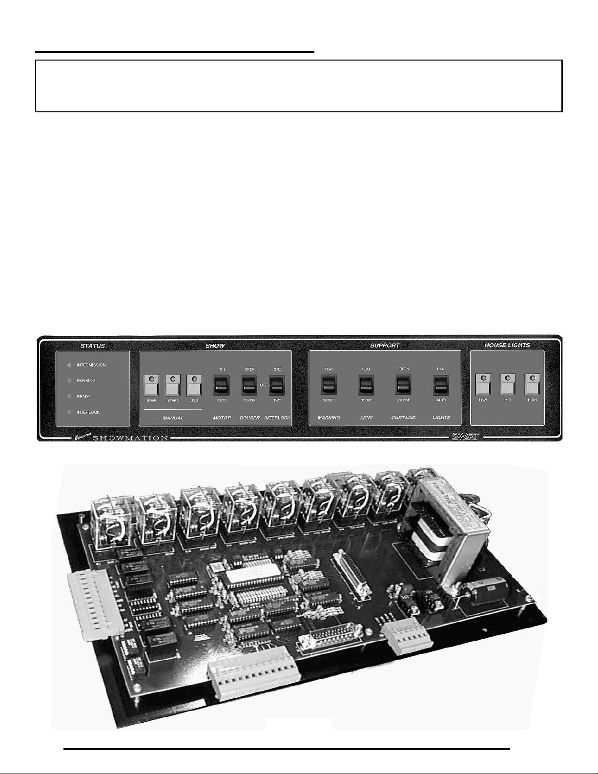
Operator Panel
Controller
3
Page 4

SHOWMATION AUTOMATION
ELECTRICAL INTERFERENCE WARNING
This device utilizes sophisticated computerized micro-controller devices and
!
other parts which may be susceptible to externally produced electro-magnetic
interference (EMI).This type of interference may be found in and around
projector lamphouses which are not very clean electrically and magnetically. It
is imperative to make certain that all sources of EMI are properly suppressed if
this device is to perform to its full potential. By far, the worst offender is the
Xenon lamp ignitor, and many lamphouses, especially older ones, have
extremely electrically dirty ignitors. Please see the diagram below for suggested
ways to clean up the lamphouse. Having an EMI suppressed system is your
responsibility, and SMART assumes no responsibility for failures due to
excessive interference.
LAMPHOUSE
XENON LAMP
Chassis
ground
points
4
IGNITOR
120 VAC Leads
3 capacitors
0.05uF to 0.1uF
at least 450 VDC
rating
LAMP DC LEADS
3 capacitors
0.1uF to 0.47uF
at least 450 VDC
rating
Keep all capacitor leads as
short as possible with the
most direct connection to
chassis ground, 2 to 3 inches
at most. Long leads will
degrade suppression. Mount
all capacitors as close as
possible to where leads exit
lamphouse.
Page 5

INSTALLATION AND OPERATION
FEATURES
Micro-Controller based
Simple Installation
All wiring on pluggable terminal strips and Faston connectors and DB25 computer type cables
Heavy duty 10 Amps continuous service relays for high current loads
1 Amp continuous service relays for low current loads
When several automations are wired together for interlock, two different interlocks may run
simultaneously
Each SHOWMATION has setup switches to properly identify itself to the WATCHDOG
annunciator panels
The OPERATOR PANEL has a scratchproof Lexan overlay which matches the SHOWGRAMMER II
All pushbuttons are high quality Schadow switches
A JOG pushbutton will run the motor as long as it is held in for ease of checking film threading. This
relieves wear and tear on the motor manual bypass switch
Light dimmer pushbuttons are available on the OPERATOR PANEL
Manual bypass switches are available for motor, douser, masking, lens, curtains, and lights
5
Page 6

SHOWMATION AUTOMATION
DESCRIPTION
This automation consists of two separate items, the Controller and the Operator Panel.
The Controller is the internal device which
mounts inside the console. It contains all the relays, wiring connectors for hookup to all the
projector and console devices, the power supply, and the micro-controller computer chip and
associated circuitry which performs all the automation functions. It also contains connectors
for hookup to the Operator Panel and to an optional SHOWGRAMMER II. This is all on a
large printed circuit board which is mounted on
a metal back plate. The back plate has four
mounting holes which will pass #8 machine
screws for securing the Controller to the inside
of the console. Alternatively, the Controller may
also be mounted in the optional Wall Mount
Package.
The Operator Panel is a 3½” high by 19” wide
rack mount assembly which mounts in any standard EIA rack mount opening. Many consoles
have provision for mounting such equipment.
The Operator Panel contains all the pushbuttons
and manual bypass switches for normal operation of a typical booth. It also contains LED indicators for the pushbutton switches and the system status. The Operator Panel has a reverse
silk-screened Lexan overlay which is very
scratch resistant and aesthetically appealing. It
contains all the legends for the switches, pushbuttons, and system status. The look matches
that of the optional SHOWGRAMMER II.
Connection from the Operator Panel to the Controller is through a DB25 Male to Female cable
for normal functions and through several wiring
harnesses for the manual bypass functions. The
harnesses are terminated to Faston connectors
on the Operator Panel end for ease of connec-
tion. The Controller end of the harnesses are terminated on Faston connectors for some functions and bare tinned wires for connection to the
pluggable connectors for other functions. These
pre-made harnesses make for an easy installation which was an important consideration in
the design.
Ease of operation was also a very important design factor, and the SHOWMATION is very
straightforward and easy to use. System Status
is easily discernible at a glance, and the operator
will appreciate the simplicity of operation.
Interlock capability is a part of the system and
goes beyond that of conventional automation
systems. The SHOWMATION has a three position Interlock selector switch with the center position being OFF, or no interlock. The UP position is Interlock 1 and the DOWN position is Interlock 2. Several automations can be wired for
interlock, and two different interlocks can be
run simultaneously with virtually any number
of screens participating. For example, lets say
that 6 screens are wired together for interlock.
Screens 1, 2, and 3 can run on Interlock 1 while
screens 5 and 6 are running on Interlock 2, and
Screen 4 is running standalone. This is accomplished by simply setting the Interlock selector
switch on each Operator Panel to the appropriate position. You can set up any combination of
screens for interlock in this way. While running,
the Interlock state can not be changed accidentally. The only time the Interlock state can be altered is in STOP mode. This prevents a condition in which film might be broken if one projector were to stop for some reason.
6
Page 7

!
INSTALLATION AND OPERATION
INSTALLATION
Take extra precautions when installing this piece of equipment. Remember that
you are dealing with dangerous voltages present inside the console. These voltages can be lethal. Even 120 VAC can KILL. Remove ALL power from the console preferably by shutting off the breakers at the main or sub panels that feed
this console. Take care when attaching high voltage wiring to the pluggable terminal strips on the automation. Do not leave any strands of wire hanging loose
which may short to the console case. Make sure that ALL connections are
TIGHT and SECURE. Leave NOTHING to chance. Remember what Murphy said: If
anything can go wrong, you will probably DIE. Well, that wasn’t exactly what he
said, but you get the point. Be careful!
Now that we have that out of the way, let’s get on to the installation.
First, we are assuming a console mounting
which will probably cover most situations. If
you are installing in a Wall Mount Package, the
steps are similar except that the Controller and
Operator Panel will be in the Wall Mount Package and you will be running wires between the
console and the Wall Mount Package.
Controller
Please refer to the diagrams that follow the Installation section for additional information on
mounting and connections to the Controller.
Find a suitable location in the console to mount
the Controller. This is not particularly critical
except for attempting to stay as far as possible
away from sources of EMI as described on Page
3 of this manual.
please do so NOW. The success of this installation may well depend on how well you have
cleaned up the console electrically.
The Controller does not generate an appreciable
amount of heat, but as with all electronic equipment, the cooler the better. So if airflow is available, take advantage of it and mount the Controller in the airflow path. Also try to locate the
Controller in close proximity to the majority of
the electrical connections to minimize the wire
lengths to the Controller.
If you have not read Page 3,
Position the Controller so that the power transformer is at the TOP or to the RIGHT. Use the
mounting holes on the metal back plate to mark
the hole positions for drilling. Drill the appropriate holes in the console mounting location
and secure the metal back plate and controller
with #8 machine screws, lockwashers, and nuts.
Follow the diagrams following the installation
section of this manual and locate the various
connection points for the Xenon Ignitor, motor,
slide projector, douser, etc. and wire each of
these items from the pluggable terminal strips
to the appropriate points in the console wiring.
Use wire sizes appropriate for the load you are
controlling.
Even with all the proper precautions taken to
minimize interference from the Ignitor, you
may still experience interference problems . If
so, contact the factory for an external relay/
cable set to use in the Ignitor circuit.
7
Page 8

SHOWMATION AUTOMATION
Configuration
Pulse or latch operation (Diagram on Page 11)
The Controller has several functions which may
be configured for either pulse or latch operation:
lens, masking, and lights. The Douser function
is always pulse mode, and the Curtains function
is always latch mode. There are 5 DIP switches
in the DIP switch package labeled SW2 which
are used to set these functions to either pulse or
latch modes. If the switch is UP (off) then the
mode is pulse. If the switch is DOWN (on), then
the mode is latch. In the pulse mode, the appropriate relay(s) will close for one second and then
open. In the latch mode, the relay(s) will close
and remain closed as long as that function is selected.
In Version 4.00 of the software, only the lens,
masking, and lights are selectable as pulse or
latch. The douser function is ALWAYS pulse
mode. The curtains function is ALWAYS latch
mode. Future versions of the software will allow the douser and curtains to be either pulse
or latch. The software version is listed on the
label on top of the micro-controller IC labeled
U8 on the Controller printed circuit board.
Annunciator ID (Diagram on Page 11)
There is another DIP switch package labeled
SW1 on the Controller printed circuit board.
These DIP switches set the Identification Code
for each Controller to allow proper communication with the optional WATCHDOG Annunciator Panel(s).
unique
ID Code so that the WATCHDOG Annunciator Panel(s) will be able to tell which
Controller is sending information about the
system status.
Each Controller must be set to a
SW1-1 SW1-2 SW1-3 SW1-4 SW1-5 ID Code
UP UP UP UP UP 1
UP UP UP UP DOWN 2
UP UP UP DOWN UP 3
UP UP UP DOWN DOWN 4
UP UP DOWN UP UP 5
UP UP DOWN UP DOWN 6
UP UP DOWN DOWN UP 7
UP UP DOWN DOWN DOWN 8
UP DOWN UP UP UP 9
UP DOWN UP UP DOWN 10
UP DOWN UP DOWN UP 11
UP DOWN UP DOWN DOWN 12
UP DOWN DOWN UP UP 13
UP DOWN DOWN UP DOWN 14
UP DOWN DOWN DOWN UP 15
UP DOWN DOWN DOWN DOWN 16
DOWN UP UP UP UP 17
DOWN UP UP UP DOWN 18
DOWN UP UP DOWN UP 19
DOWN UP UP DOWN DOWN 20
DOWN UP DOWN UP UP 21
DOWN UP DOWN UP DOWN 22
DOWN UP DOWN DOWN UP 23
DOWN UP DOWN DOWN DOWN 24
DOWN DOWN UP UP UP 25
DOWN DOWN UP UP DOWN 26
DOWN DOWN UP DOWN UP 27
DOWN DOWN UP DOWN DOWN 28
DOWN DOWN DOWN UP UP 29
DOWN DOWN DOWN UP DOWN 30
DOWN DOWN DOWN DOWN UP 31
DOWN DOWN DOWN DOWN DOWN 32
You should set each Controller’s ID Code to
match the screen number.
This way the
WATCHDOG Annunciator Panel(s) will indicate the system status properly for each screen
There are 32 possible codes which can be selected. To set a code, push the appropriate
switches DOWN (on). Use the following table to
determine the ID Codes for each Controller.
8
Operator Panel
Find a suitable place in the console for the Operator Panel to mount. The panel is a 3½” high by
19” wide rack mount which will fit any stan-
Page 9

INSTALLATION AND OPERATION
dard EIA rack opening. Plug the supplied DB25
male to female cable into the connector on the
Operator Panel circuit board. Plug the other end
of the cable into the connector on the Controller.
There are six wiring harnesses supplied which
are used to connect the Operator Panel manual
switches to the Controller. Each harness is labeled at each end. The ends that are labeled F1PANEL through F16-PANEL go to the FASTON connectors on the Operator Panel circuit
board.
nesses to the correct points at each end. Incorrect connections could result in dangerous
voltages being applied to places they should
not be. This could result in disastrous consequences. Please use the table on PAGE 12 for a
complete listing of all the harness connections.
After connecting these harnesses to the Operator Panel, connect the other ends to the appropriate points on the Controller. Two of the harnesses have bare tinned wires on the Controller
end for connection to the pluggable terminal
strips. These harnesses are for high lights and
lens flat or scope manual functions. They will be
wired to the terminal strips together with the
wires from the lens change controller and the
light dimmer unit(s).
SHOWGRAMMER II
Mount the SHOWGRAMMER II close to the
Operator Panel, preferably directly below it.
Plug the DB25 cable into the DB25 connector on
the Controller. Plug the other end of the DB25
cable into the DB25 connector on the Showgrammer II. See the SHOWGRAMMER II manual for hookup information regarding connections to the sound processor.
It is very important to attach these har-
Interlock Wiring
All interlock wiring should use 2 conductor plus
shield cable. Refer to the diagram on Page 11 for
the pluggable terminal strip labeled as TB3. You
will need 2 of the 2 conductor plus shield cables
to connect between each automation that you
desire to wire for interlock. The first cable will
connect Interlock 1 Start, Interlock 1 Stop, and
Interlock Common together. The second cable
will connect similar terminals for Interlock 2.
Use the the 2 conductors for the Start and Stop
functions, and the shield for the Interlock Common. If several automations are wired together
for Interlock the cables will just daisy chain
from one to the next and so on.
Annunciator Panel Wiring
The Annunciator Panel wiring is done similarly
to the Interlock wiring. You may use the same 2
conductor cable as for the interlock wiring if
you like.
The shields of the cables will connect to the Com
terminal on TB6 of each automation. The hot
conductors will attach to the Data terminals on
TB3 of each automation. Wire one cable to the
DATA IN LO and DATA IN HI terminals. Wire
the other cable to the DATA OUT LO and
DATA OUT HI terminals.
You may only wire up to 32 automations together. Run cables from any of the automations
to the location where the Annunciator panel
will be mounted.
On all DB25 connectors, secure the connectors
with the two thumb screws provided on each
connector.
9
Page 10

SHOWMATION AUTOMATION
Controller Installation
Mount the Controller in the console as shown in this diagram. The power transformer should be at
the TOP or RIGHT. Please note that the the metal back plate is NOT symmetrical and cannot be
turned upside down. The PC board will only mount one way on the panel. There are four mounting
holes on the metal back plate which will pass #8 machine screws. These are accessible without
removing the PC board from the metal panel. The power cord may be plugged in or the plug may be
cut off for direct wiring to a 120VAC source.
Power Connections
F12 & F13
MDL2 Fuse Slow Blow
DB25 cable from
Operator Panel
DB25 cable from
Showgrammer II
10
Page 11
INSTALLATION AND OPERATION
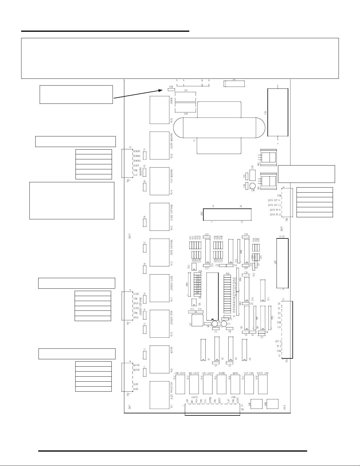
Controller Wiring Information
This page shows the functions for the 6 position pluggable terminal strips. All relays are rated at 10
Amps. If you are controlling a higher current device, then use an external relay of the proper
capacity controlled by the on board relay. Use wire size appropriate for the load to be controlled.
R39 NOT installed unless
directed by the factory.
6 position connector - TB5
Xenon 1
Xenon 2
Xenon 3
Masking Scope
Masking Common
Masking Flat
Use the XENON 1 and XENON 2
terminals for the Ignitor control
circuit. Do NOT use XENON 3
except in special cases as
directed by the factory.
6 position connector
TB6
N/C
Com
Data Out Hi
Data Out Lo
Data In Hi
Data In Lo
6 position connector - TB4
Curtains Close
Curtains Common
Curtains Open
Douser Close
Douser Common
Douser Open
6 position connector - TB2
Motor
Motor
N/C
N/C
Slide Projector
Slide Projector
11
Page 12

SHOWMATION AUTOMATION
Controller Wiring Information
This page shows the functions for the 12 position pluggable terminal strips. Lights and Lens relays
are rated at 1 Amp. If you are controlling a higher current device, then use an external relay of the
proper capacity controlled by the on board relay. The Interlock functions on TB3 will be wired in the
field. Use one 2 conductor shielded cable for each of the two interlock functions. Connect the
shields to Interlock Common. Connect all like terminals together on the projectors you wish to be
interlocked.
Lens Scope
Lens Com
Lens Flat
N/C
Future 2
Com
Future 1
Lights Full
Lights Com
Lights High
Lights Mid
Lights Low
12 position connector - TB1
12 position connector - TB3
Interlock 2 Stop
Interlock 1 Stop
Interlock 2 Start
Interlock 1 Start
Interlock Common
+24
N/C
N/C
Outboard Cue
Inboard Cue
Common
Failsafe Switch (Open when
SW1
12345
DIP Switch for
selecting ID Number
threaded)
not
CURTAINS
MASKING
DOUSER
LIGHTS
SW2
LENS
12345
DIP Switch for selecting
Pulse or Latch
12
Page 13

INSTALLATION AND OPERATION
Operator Panel and Showgrammer Installation
Mount the Operator Panel and optional Showgrammer in the space provided in the console. Mount
the Operator Panel on top with the optional Showgrammer below it. Plug a Male to Female DB25
cable into the DB25 connector on the Showgrammer. Plug the other end into the DB25 connector
marked DB1 on the Controller. Plug the other Male to Female DB25 cable into the DB25 connector
on the Operator Panel. Plug the other end into the DB25 connector marked DB2 on the Controller.
There are several wiring harnesses with Faston connectors supplied. These must be attached between the Operator Panel and the Controller (Main Board). These harnesses are color coded to
show the appropriate points of connection at each end. Please refer to the chart below for the correct connections. Note that some wires are 16 Gauge and some are 24 Gauge.
Operator Panel
Terminal Designator
and Cable Color
F1 BLUE 24 W/FASTON TB1-4 BLUE 24 STRIPPED Lights Common
F2 RED 24 W/FASTON TB1-5 RED 24 STRIPPED Lights Full
F3 ORANGE 16 GA W/FASTON F6 ORANGE 16 GA W/FASTON Curtains Open
F4 WHITE 16 GA W/FASTON F7 WHITE 16 GA W/FASTON Curtains Common
F5 BROWN 16 GA W/FASTON F8 BROWN 16 GA W/FASTON Curtains Close
F6 BROWN 24 GA W/FASTON TB1-10 TB1-10-MAIN STRIPPED Lens Flat
F7 WHITE 24 GA W/FASTON TB1-11 TB1-11-MAIN STRIPPED Lens Common
F8 GREY 24 GA W/FASTON TB1-12 TB1-12-MAIN STRIPPED Lens Scope
F9 VIOLET 16 GA W/FASTON F9 VIOLET 16 GA W/FASTON Masking Flat
F10 GREEN 16 GA W/FASTON F10 GREEN 16 GA W/FASTON Masking Common
Controller (Main Board)
Terminal Designator
and Cable Color
Bypass Function
F11 PINK 16 GA W/FASTON F11 PINK 16 GA W/FASTON Masking Scope
F12 BLUE 16 GA W/FASTON F3 BLUE 16 GA W/FASTON Douser Open
F13 GREY 16 GA W/FASTON F4 GREY 16 GA W/FASTON Douser Common
F14 YELLOW 16 GA W/FASTON F5 YELLOW 16 GA W/FASTON Douser Close
F15 BLACK 16 GA W/FASTON F1 BLACK 16 GA W/FASTON Motor
F16 RED 16 GA W/FASTON F2 RED 16 GA W/FASTON Motor
13
Page 14

SHOWMATION AUTOMATION
OPERATING INSTRUCTIONS
Operation of the SHOWMATION is very
straightforward and simple. See the OPERATOR PANEL QUICK REFERENCE on Page 15
for a quick explanation of the Indicator LED’s,
Pushbuttons, and Switches.
Cues
When used in conjunction with a SHOWGRAMMER II, you have complete control of the film
presentation. This is done by setting the various
switches on the SHOWGRAMMER II and by
placing cues on the film at the appropriate
places to initiate the desired format, lens, masking, and lighting changes.
All cues are to be placed on the
the film when the SHOWMATION and SHOWGRAMMER II are used together. (When the
SHOWMATION is used as a standalone system,
then cues may also be placed on the outboard
side of the film. This is a special situation which
will be detailed in a separate manual for the
standalone SHOWMATION.)
This SHOWMATION system ALWAYS requires
a cue at PICTURE START. The douser will
open until the PICTURE START cue passes. This
is also a requirement for Interlock Operation, so
placing a cue at PICTURE START will serve
both purposes.
See the SHOWGRAMMER II manual for details
on programming the desired format, lens and
masking, and lighting changes. In addition to
the cue at PICTURE START, one cue will be required at every point in the film where you desire to make any change. Format, lens and
masking, and lighting changes may be done in
any combination on any cue. The START cue
will open the douser and advance the SHOWGRAMMER II to the START position. Format,
inboard
side of
not
lens and masking, and lighting changes which
have been programmed on the SHOWGRAMMER II START position will go into effect on the
FIRST cue. There may be
the Start cue to control format, lens and masking, and lighting changes.
For example, the START cue could be set up for
MONO, FLAT and MID lights. The next cue
could change to STEREO A, SCOPE, and MID
lights, the next cue could change to STEREO SR,
SCOPE, and LOW lights. The next cue could be
at the credits and could just change the house
lights to MID for early house lights.The next cue
placed at the end of the credits could change the
SHOWGRAMMER II to end of show which will
bring up MUSIC format and close the douser.
Then when the failsafe drops, the system will
stop and be ready for re-threading for the next
show.
If you have used
(PICTURE START plus four more) for format,
lens and masking, and lighting changes, there is
one more available cue which will tell the
SHOWGRAMMER II that the end of show is
here. This cue is not programmable on the
SHOWGRAMMER II, but the SHOWGRAMMER II will recognize this sixth cue and initiate
an end of show condition. This cue will be
placed at the end of credits.
As with other systems, make sure the cues are
properly applied and are in good condition. A
good presentation depends on the cues, and failure to pay good attention to this part of preparing your film will result in poor performance.
Operation
When the SHOWMATION is in intermission
mode, the INTERMISSION LED will be on. As
all five
available cues
more cues after
four
14
Page 15

INSTALLATION AND OPERATION
the film is threaded and the failsafe is raised, the
READY LED will come on. The system will not
start unless the READY LED is on. The RUNNING LED will be off at this point. In addition
the LED in the STOP pushbutton will be on. The
INTERLOCK LED will be off unless you have selected an interlock mode with the INTERLOCK
switch.
As an aid in threading, the SHOWMATION provides a JOG function. When you push the JOG
pushbutton, the motor will run. When you release
the JOG pushbutton, the motor will stop. Use this
feature rather than the MOTOR manual switch.
This saves wear and tear on the manual switch.
The STOP pushbutton will not normally be used
except when there is a problem. If you start the
show and the film is not feeding properly, for example, you may push the STOP pushbutton to
stop the projector. After the problem is corrected,
push the START pushbutton to re-start the show.
Once the film is threaded and you are ready to
start the show, push the START pushbutton. The
INTERMISSION LED and the STOP pushbutton
LED will go off and the RUNNING LED and the
START pushbutton LED will come on. The projector will start running and the lamp will strike.
When the PICTURE START cue comes along, the
douser will open.
At this point, no further attention is required unless a film break occurs. If the film breaks, the LED
in the STOP pushbutton will blink rapidly. Simply
repair the film and re-thread. Then push the
START button to re-start the show. After a 7 second delay, the douser will open automatically. If
you wish the douser to open sooner, press the JOG
pushbutton which doubles as a timer bypass
switch.
The manual switches are there in the event that
the SHOWMATION is not functioning correctly.
These are self-explanatory. Normally you should
not have to use the manual switches unless there
is a problem such as the lens and masking are not
in the correct format. In that case use the manual
switches to correct the problem.
The HOUSE LIGHTS pushbuttons may be used at
any time to change the house lights levels. Normally, the house lights levels are controlled by the
SHOWGRAMMER II programming and the cues
on the film, so it is usually not necessary to use
these pushbuttons unless there is a problem. The
LED’s in these pushbuttons will change as the
SHOWGRAMMER II programming dictates so
you may tell at a glance what the house lights levels are.
The LIGHTS switch should always be in the
AUTO position so that the SHOWMATION can
control the lights. However, in an emergency this
switch can be used to
house lights levels, and when placed in the HIGH
position will bring the house lights to full brightness.
Interlock
The SHOWMATION has a three position INTERLOCK selector switch with the center position being OFF, or no interlock. The UP position is Interlock 1 and the DOWN position is Interlock 2. Two
different interlocks can be run simultaneously
with virtually any number of screens participating. For example, lets say that 6 screens are wired
together for interlock. Screens 1, 2, and 3 can run
on Interlock 1 while screens 5 and 6 are running
on Interlock 2, and Screen 4 is running standalone.
This is accomplished by simply setting the Interlock selector switch on each Front Panel to the appropriate position. You can set up any combination of screens for interlock in this way. While running, the Interlock state can not be changed accidentally. The only time the Interlock state can be
altered is in STOP mode. This prevents a condition
in which film might be broken if one projector
were to stop for some reason.
override
the programmed
15
Page 16
SHOWMATION AUTOMATION
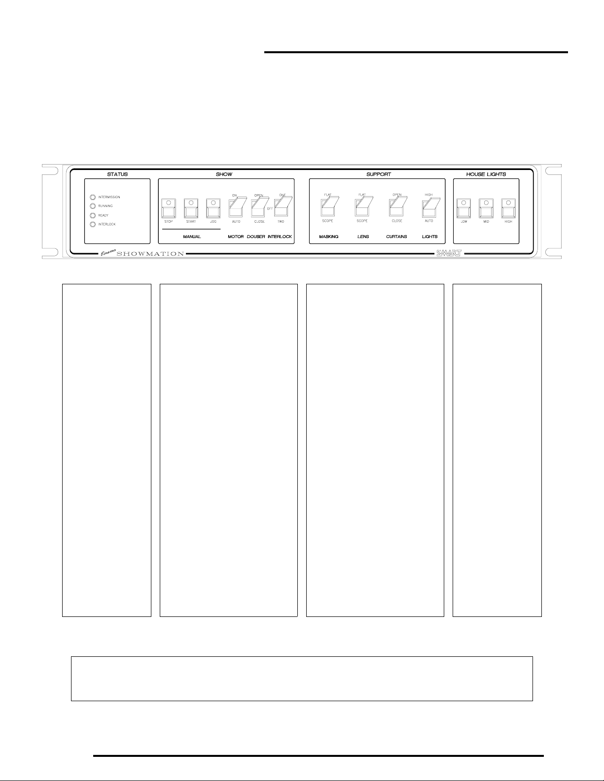
OPERATOR PANEL QUICK REFERENCE
The STATUS LED’s
indicate the current
state of the system.
The READY led is on
when the failsafe is
up.The system will not
start unless the
READY LED is on.
The RUNNING LED
comes on when the
show is started.
The INTERMISSION
LED is on between
shows.
The INTERLOCK LED
is on when one of the
two Interlocks is
selected
These switches and pushbuttons
control the major show functions.
The START pushbutton is used to
begin the show. The START LED
will be on while the show is running.
The STOP pushbutton will stop the
show, but will not normally need to
be pushed. The STOP LED will be
on during intermission and will be
rapidly blinking during a film break.
The JOG pushbutton is used to
momentarily run the motor to feed
film as an aid in threading up. Hold it
in to run the motor, and release it to
stop the motor. The JOG pushbutton
is also used as a timer bypass for
the 7 second douser open timer.
The MOTOR and DOUSER toggle
switches are for manual operation
and will not normally be used.
These toggle switches control the
show support functions.
The MASKING and LENS switches
are for manual operation and will not
normally be used unless the
masking or lens is set to the
incorrect format. Push these
switches to the FLAT or SCOPE
positions to select the
correct format.
The CURTAINS and LIGHTS
switches are for manual operation of
the curtains and for bringing the
house lights to maximum in an
emergency situation.
The HOUSE LIGHTS
pushbuttons can be
used to manually
select the lighting
levels desired.
The LED’s in the
pushbuttons indicate
the selected level.
Normally, the levels
are controlled by the
SMART
SHOWGRAMMER
which operates in
conjunction with the
automation system.
16
In a film break, the automation will shut down the projector. The STOP pushbutton will blink rapidly. After repairing the break
and re-threading, push the START pushbutton to re-start the show. Wait briefly to see that all is running OK and then push the
DOUSER toggle switch to the OPEN position to open the douser.
 Loading...