

Page 1
Was this document helpful?
smarttech.com/docfeedback/171257
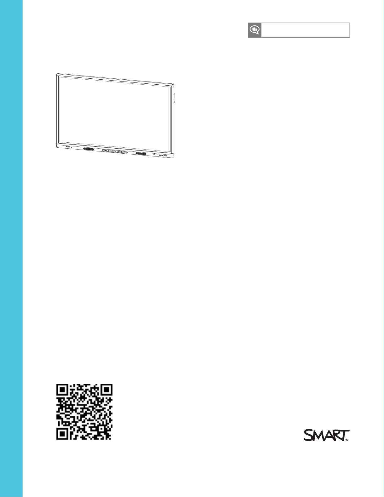
SMARTBoard MX series
interactive displays
INSTALLATION AND MAINTENANCE
FOR MODELS:
SBID-MX265
l
SBID-MX275
l
SBID-MX286
l
Page 2

Trademark n ot ice
SMARTBoard, smarttech, the SMART lo go and all SMART taglines are trademarks or re gistere d trad emarks of S MARTTechnologiesU LC i n the U.S. and/or o ther
countries. All third-party product and company names may be trademarks o f their re spe ctive owners.
Copyrigh t no tice
© 2 018SMARTTe chnologiesULC. All rig hts r es erved . No part o f this p ublication may b e r ep ro duced , transmitted, transcribe d, stored ina retrieval system or
translated into any language i n any form by any means without the pri or written conse nt o f SMARTTechnologiesU LC. Information in this manual is subject to change
without notice and does not rep re se nt a commitmenton the p art of SMART.
This prod uct and/or use thereof is co vered by one or more of the foll owing U.S. patents:
www.smarttech.com/patents
06-2018
smarttech.com/kb/171257
Page 3

Important information
IMPORTANT
There are critical software updates for the display that you need to install to ensure the display is
fully functional and provides the best experience. Connect the display and iQ appliance to a
wired or wireless network with Internet access to automatically download and apply these
updates as well as future updates.
WARNING
l Failure to follow the installation instructions shipped with the SMART product could result in
injury and product damage which may not be covered by the warranty.
l Do not open or disassemble the SMART product. You risk electrical shock from the high
voltage inside the casing. Opening the casing also voids the warranty.
l Do not stand (or allow children to stand) on a chair to touch the surface of the SMART
product. Rather, mount the product at the appropriate height.
l To reduce the risk of fire or electric shock, do not expose the SMART product to rain or
moisture.
l If the SMART product requires replacement parts, make sure the service technician uses
replacement parts specified by SMARTTechnologies or parts with the same characteristics
as the original.
l Ensure that any cables that cross the floor to the SMART product are properly bundled and
marked to avoid a trip hazard.
l Do not insert objects inside the cabinet ventilation holes, because they could touch
dangerous voltage points and cause electric shock, fire or product damage which may not
be covered by the warranty.
l Do not place heavy objects on the power cable. Damage to the cable could cause shock,
fire or product damage which may not be covered by the warranty.
l Useonly extension cords and outlets that can fully accommodate the display’s polarized
plug.
i smarttech.com/kb/171257
Page 4
IMPORTANT INFORMATION
l Use the power cable provided with the display. If a power cable is not supplied, contact
your supplier. Use only power cables that match the AC voltage of the power outlet and that
comply with your country’s safety standards.
l If the glass is broken, do not touch the liquid crystal. To prevent injury, handle glass
fragments with care when disposing of them.
l Do not move or mount the display by connecting rope or wire to its handles. The display is
heavy, and failure of the rope, wire or handle could lead to injury.
l Use only VESA®-approved mounts if using a mount other than the one supplied with the
display..
l Disconnect all of the display’s power cables from the wall outlet and seek assistance from
qualified service personnel if any of the following occur:
o
The power cable or plug is damaged
o
Liquid is spilled into the display
o
Objects fall into the display
o
The display is dropped
o
Structural damage, such as cracking, occurs
o
The display behaves unexpectedly when you follow operating instructions
l Before inserting or removing the iQ appliance from the display, turn off the display using the
switch at the back of the display. See Open Pluggable Slot computer (OPS) disclaimer for
more information.
CAUTION
l Turn off the display before cleaning its screen. Otherwise, you may scramble the desktop
icons or inadvertently activate applications when you wipe the screen.
l Avoid setting up and using the SMART product in an area with excessive levels of dust,
humidity and smoke.
l Make sure an electrical socket is near the SMART product and remains easily accessible
during use.
ii smarttech.com/kb/171257
Page 5
IMPORTANT INFORMATION
l The SMART product should be used only with European TN and TT power distribution
systems.
It is not suitable for older, IT-type power distribution systems found in some European
countries. This system (IT-type) is widely used isolated from earth, in some installations in
France, with impedance to earth, at 230/400V, and in Norway, with voltage limiter, neutral
not distributed, at 230V line-to-line.
Contact qualified personnel if you’re uncertain of the type of power system available where
you’re installing the SMART product.
l The accessory slot’s maximum available power is 60 W. The slot is not a limited power
source. To reduce the risk of fire, make sure that accessories connecting to the slot satisfy
the fire enclosure requirements of IEC60950-1.
l You must connect the USB cable that came with the SMART product to a computer that has
a USB compliant interface and that bears the USB logo. In addition, the USB source
computer must be compliant with CSA/UL/EN 60950 and bear the CE mark and CSA and/or
UL Mark(s) for CSA/UL 60950. This is for operating safety and to avoid damage to the
SMART product.
IMPORTANT
l The following are the normal operating requirements for the display, including AM module
and speakers:
Model Power requirements
SBID-MX265 100V to 240V AC, 50 Hz to 60 Hz, 115 W max
SBID-MX275 100V to 240V AC, 50 Hz to 60 Hz, 224 W max
SBID-MX286 100V to 240V AC, 50 Hz to 60 Hz, 265 W max
l For additional requirements and other information, refer to the display’s specifications (see
More information on page9).
Federal Communication Commission interference statement
This device complies with Part 15 of the FCC Rules.Operation is subject to the following two conditions:
1. This device may not cause harmful interference, and
2. this device must accept any interference received, includinginterference that may cause undesired operation.
iii smarttech.com/kb/171257
Page 6
IMPORTANT INFORMATION
NOTE
This equipment has been tested and found to complywith the limits for a Class A digital device,pursuant to part 15 of the
FCC Rules. These limits are designed to providereasonable protection against harmful interference when the equipment is
operated in a commercial environment. This equipment generates, uses, and can radiate radio frequency energy and, if not
installedand used in accordance with the instruction manual, may cause harmful interference to radio communications.
Operation of this equipment in a residentialarea is likelyto cause harmful interference in which case the user will be
required to correct the interference at his own expense.
CAUTION
Any changes or modifications not expressly approved by the party responsible for compliance could voidthe user’s
authority to operate this equipment.
Radiation exposure statement
This equipment complies with FCC radiation exposure limitsset forth for an uncontrolledenvironment. This equipment should
be installed and operated with minimum distance of 20 cm between the antenna ofthis device and all nearby persons. This
transmitter must not be co-located or operated in conjunction with any other antenna or transmitter.
Innovation, Science and Economic Development Canada statement
This device complies with RSS-247of the Innovation, Science and EconomicDevelopment Canada Rules. Operation is subject
to the following two conditions:
1. This device may not cause harmful interference, and
2. this device must accept any interference received, includinginterference that may cause undesired operation.
Radiation exposure statement
This equipment complies with ISED radiation exposure limitsset forth for an uncontrolledenvironment. This equipment should
be installed and operated with minimum distance of 20 cm between the antenna ofthis device and all nearby persons. This
transmitter must not be co-located or operated in conjunction with any other antenna or transmitter.
Cet appareil est conforme à la norme ISED CNR-247 pour les appareilsradio agréés. Son fonctionnement est soumis aux deux
conditions suivantes:
1. le dispositifne doit pas produire de brouillage préjudiciable,et
2. ce dispositifdoit accepter tout brouillage reçu, y compris un brouillage susceptible de provoquer un fonctionnement
indésirable.
Déclaration d’exposition aux radiations
Cet équipement est conforme aux limites d’exposition aux rayonnements ISED établiespour un environnement non contrôlé.
Cet équipement doit être installéet utilisé avec un minimum de 20 cm de distance entre la source de rayonnement et votre
corps. Cet émetteur ne doit pas être co- implantés ou exploités conjointement avec une autre antenne ou émetteur.
EU declaration of conformity: AM40
Hereby, SMART Technologies ULC declares that the radio equipment type OPS, AM40 is in compliance with Directive
2014/53/EU.
The fulltext of the EUdeclaration of conformity is availableat the followinginternet address: smarttech.com/compliance
The frequency band and the maximum transmitted power in EUare listedbelow:
iv smarttech.com/kb/171257
Page 7
IMPORTANT INFORMATION
Transmitting Band (MHz) Maximum Transmit Power EIRP (dBm)
2400–2483.5 19
5150–5350 16
5470–5725 16
Restrictions in
AT/BE/BG/CZ/DK/EE/FR/DE/IS/IE/IT/EL/ES/CY/LV/LI/LT/LU/HU/MT/NL/NO/PL/PT/RO/SI/SK/TR/FI/SE/CH/UK/HR.5150MHz5350MHz is for indoor use only.
CAUTION: EXPOSURE TO RADIO FREQUENCY RADIATION
This equipment complies with EU radiation exposure limits set forth for an uncontrolled environment. This equipment should
be installed and operated with minimum distance 20 cm between the radiator and your body.
v smarttech.com/kb/171257
Page 8

Page 9

Contents
Important information i
Federal Communication Commission interference statement iii
Innovation, Science and Economic Development Canada statement iv
EU declaration of conformity: AM40 iv
Chapter 1: Welcome 1
About this guide 1
About the SMARTBoard MX 2
Components 3
Related products 7
More information 9
Chapter 2: Installing the display 11
Transporting the display 11
Installing the display on a wall 13
Installing the display on a stand 20
Chapter 3: Connecting power and devices 21
Connecting the iQ appliance 21
Connecting power 22
Connecting to a network 22
Connecting cables for room computers, guestlaptops and other input sources 23
Connecting room control systems 26
Connector reference 27
Chapter 4: Configuring the display 31
Turning on the display for the first time 32
Connecting the display and iQ appliance to a network 33
Updating system software 40
Updating iQ system software 40
Updating the display’s firmware 41
Locking down the Settings app for iQ system software 43
Switching the iQ system software to the Beta channel 44
Adding or removing apps from the launcher 47
Enabling the Whiteboard Library 47
Chapter 5: Configuring connected computers 49
Installing SMART software on connected computers 49
Setting connected computers’ resolutions and refresh rates 50
vii smarttech.com/kb/171257
Page 10

CONTENTS
Chapter 6: Maintaining the display 51
Checking the display installation 51
Cleaning the screen 51
Cleaning the touch sensors 52
Maintaining ventilation 53
Preventing condensation 53
Replacing the pens 53
Turning the display off and back on 53
Resetting the display 54
Removing and transporting the display 54
Chapter 7: Troubleshooting 57
Troubleshooting the display 57
Troubleshooting the iQ system software 62
Referring to the SMART knowledge base for additional troubleshooting information 73
Contacting your reseller for additional support 73
Appendix A: Using iQ system settings 75
Network settings 75
Application settings 75
System settings 76
Appendix B: Using display settings on your SMARTBoard MX 79
Accessing the display’s settings 79
Exiting the display’s settings 79
Network 80
Screen lock 80
Advanced 81
Update 82
Recovery 82
About 83
Appendix C: Remotely managing the display 85
Connecting a computer to the display 86
Configuring the computer’s serial interface settings 86
Power states 87
Commands and responses 88
Commandinventory 89
Resolving issues with remote management 92
Appendix D: Identifying your display 93
Identify your display 93
Appendix E: Supported resolutions 95
HDMI1 in, HDMI 2 in and HDMI 3 in 95
viii smarttech.com/kb/171257
Page 11

CONTENTS
VGA 95
Appendix F: Hardware environmental compliance 97
Waste Electrical and Electronic Equipment and Battery regulations (WEEE and Battery
Directives) 97
Batteries 97
More information 97
ix smarttech.com/kb/171257
Page 12

Page 13

Chapter 1
About this guide 1
About the SMARTBoard MX 2
Features 2
Identifying your SMARTBoard MX series interactive display model 3
Components 3
iQ appliance 4
Screen 4
Pens 4
Front connector panel 5
Front control panel 5
Remote control 6
Remote control sensor 7
Status light 7
Ambient light sensor 7
Internal speakers 7
Related products 7
SBA-100 projection audio system 8
SMART Audio 400 classroom amplification system 8
USB extenders 8
More information 9
This chapter introduces the SMARTBoard® MX series interactive displays.
About this guide
This guide explains how to install and maintain a SMARTBoard MX series interactive display. It
includes the following information:
l How to install the display
l How to connect power and devices
l How to turn on the display for the first time
l How to configure the iQ appliance
1 smarttech.com/kb/171257
Page 14

CHAPTER1
WELCOME
l How to maintain the display for years of use
l How to troubleshoot issues with the display
In addition, this guide includes information on the display’s settings and remote management
support.
This guide is intended for those who install and maintain displays in their organizations. Other
documentation and resources are available for those who use displays (see More information on
page9).
About the SMARTBoard MX
The SMARTBoard MX series interactive display is the hub of your classroom or meeting room.
PC-free embedded computing provides one-touch access to collaborative tools, including a
whiteboard, wireless screen sharing and a web browser. There’s no need for wires, cables or
manual software and firmware updates.
Features
The display includes the following features:
Feature Description
iQ technology The display’s iQ appliance provides one-touch access to
collaborative tools, including a whiteboard, wireless screen sharing
and a web browser.
Touch support You can do everything on the display that you can do at your
computer—open and close applications, meet with others, create
new documents or edit existing ones, visit websites, play and
manipulate videos, and so on—by touching the display’s surface.
You can use an array of gestures within applications, including
panning, scaling, rotating and zooming in and out.
The display’s support for up to 10 simultaneous touch, writing and
erase points enables you and other users to interact with objects
on the screen at the same time.
Writing and drawing
support
You can write over applications in digital ink using one of the
supplied pens, and then erase the digital ink using your palm.
Up to two users can write or draw digital ink on the screen at the
same time.
Audio support The display includes integrated speakers for presenting audio from
connected input sources.
1
1
Requires SMART Product Drivers to be installed.Some applications might not support all touch points.
2 smarttech.com/kb/171257
Page 15
CHAPTER1
WELCOME
Identifying your SMARTBoard MX series interactive display model
The following models of SMARTBoard MX series interactive display are available:
Model Screen size (approximate)
SBID-MX265 65" (165 cm)
SBID-MX275 75" (190 cm)
SBID-MX286 86" (218 cm)
Refer to the specifications for detailed technical information for this model, including product
dimensions and weights (see More information on page9).
For help identifying your display, see Appendix D: Identifying your display on page93.
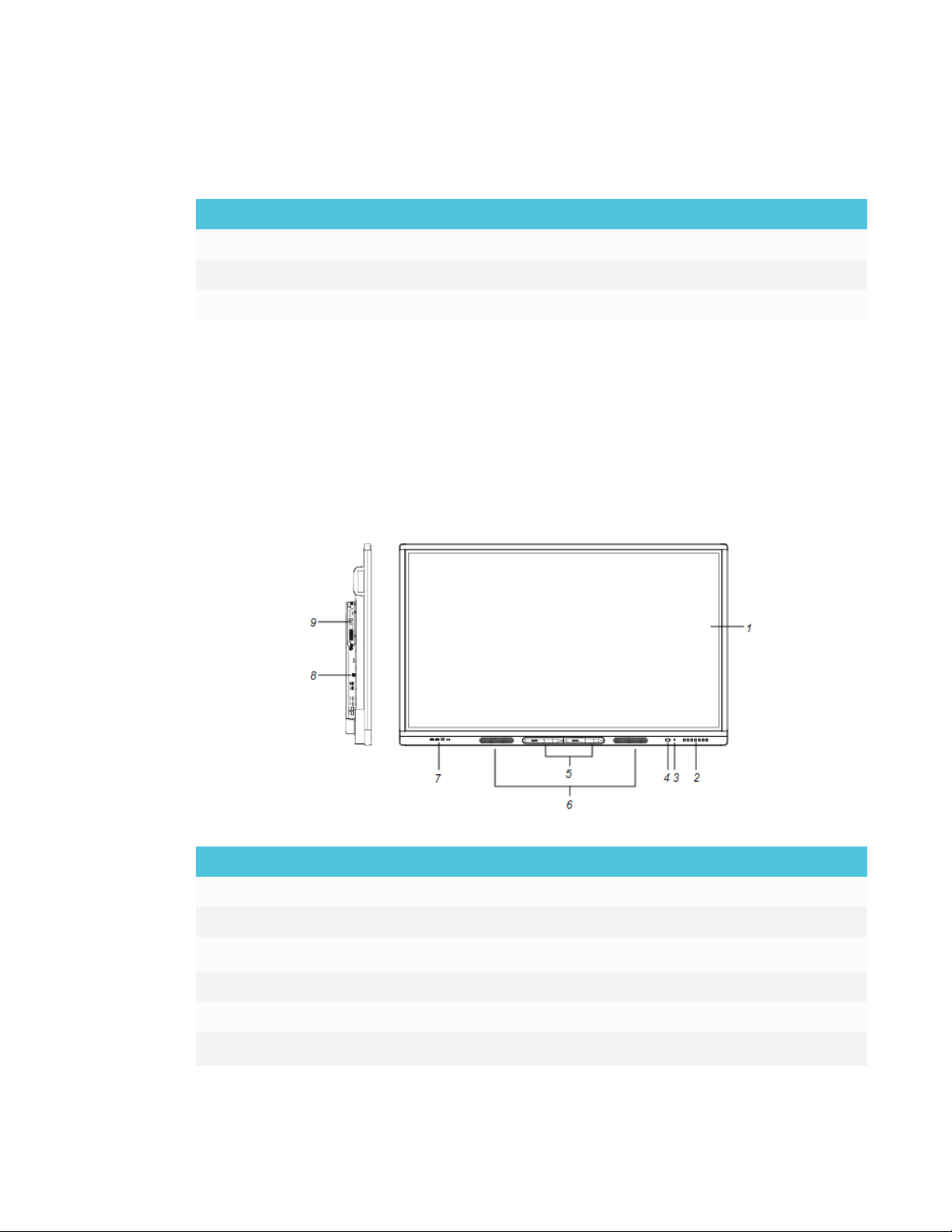
Components
The display consists of the following components:
No. Name More information
Pictured
1 Screen Page4
2
3 Light sensor page7
4 Remote control sensor / status light page7
5
3 smarttech.com/kb/171257
Front control panel Page5
Pen (×2) Page4
Page 16
CHAPTER1
WELCOME
No. Name More information
6
7 Front connector panel
8
9
Speakers Page7
Page5
Side connector panel page27
iQ appliance Page4
Not pictured
10 AC and switch page32
11 Bottom connector panel Page21
12 Remote control page6
iQ appliance
The iQ appliance is inserted in the accessory slot on the back of the SBID-MX265, SBID-MX275
and SBID-MX286 models.
The accessory slot’s maximum available power is 60 W. The slot is not a limited power source.
To reduce the risk of fire, make sure that accessories connecting to the slot satisfy the fire
enclosure requirements of IEC60950-1.
Screen
The following are the dimensions for the display:
Model Diagonal Active touch area Active image area
SBID-MX265 64 1/2" (163.9cm) 573/8" × 32 3/4" (145.7cm ×
83.3cm)
SBID-MX275 74 1/2" (189.3 cm) 66 1/2" × 38" (168.8cm ×
96.6cm)
SBID-MX286 85 5/8" (218.4 cm) 763/8" × 43 3/4" (194.1 cm ×
111.2cm)
56 1/4" ×31 5/8" (142.9cm × 80.4
cm)
65" × 36 1/2" (165 cm × 92.8cm)
74 5/8" × 42" (189.5 cm ×
106.6cm)
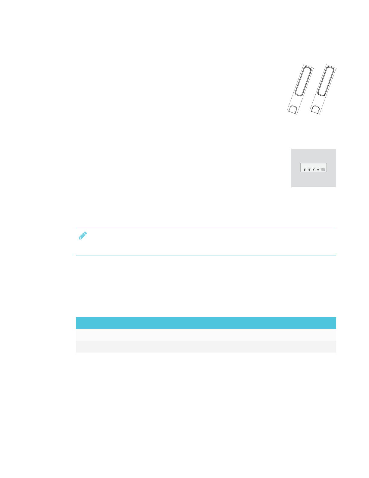
Pens
The display comes with two pens.
The display’s bottom frame includes magnetic holders for the pens. Remove a pen from its holder
and use the pen to draw digital ink.
4 smarttech.com/kb/171257
Page 17

CHAPTER1
WELCOME
CAUTION
When you return a pen to the magnetic holder, make sure it’s centered in its holder to keep it
from falling and being damaged.
Front connector panel
The front connector panel includes connectors for USB
peripherals and a computer or other input source.
No. Name Procedure
1 USB Type-A connector Connect USB drives and other devices that
you want to use with the currently selected
input source.
2 USB Type-A connector Connect a USBdrive to update the display’s
firmware.
3 USB Type-B connector
4 HDMI 3 input connector Connect a computer or other input source to
Connect a USB cable to the display and
computer to provide touch control of the
computer connected to HDMI 3.
the display (see page23).
Front control panel
The front control panel contains the Power, Input Select, Menu,
Freeze, Mute and volume control buttons.
No. Name SMARTBoard MX procedure
1 Power Press to wake the display.
Press to again enter Sleep mode.
2
5 smarttech.com/kb/171257
Input select Press to switch input source.
Page 18
CHAPTER1
WELCOME
No. Name SMARTBoard MX procedure
3
Menu Press to open the display’s settings.
4 Freeze
5
6
7
Mute Press to mute or unmute the volume.
Volume decrease Press to turn down the volume.
Volume increase Press to turn up the volume.
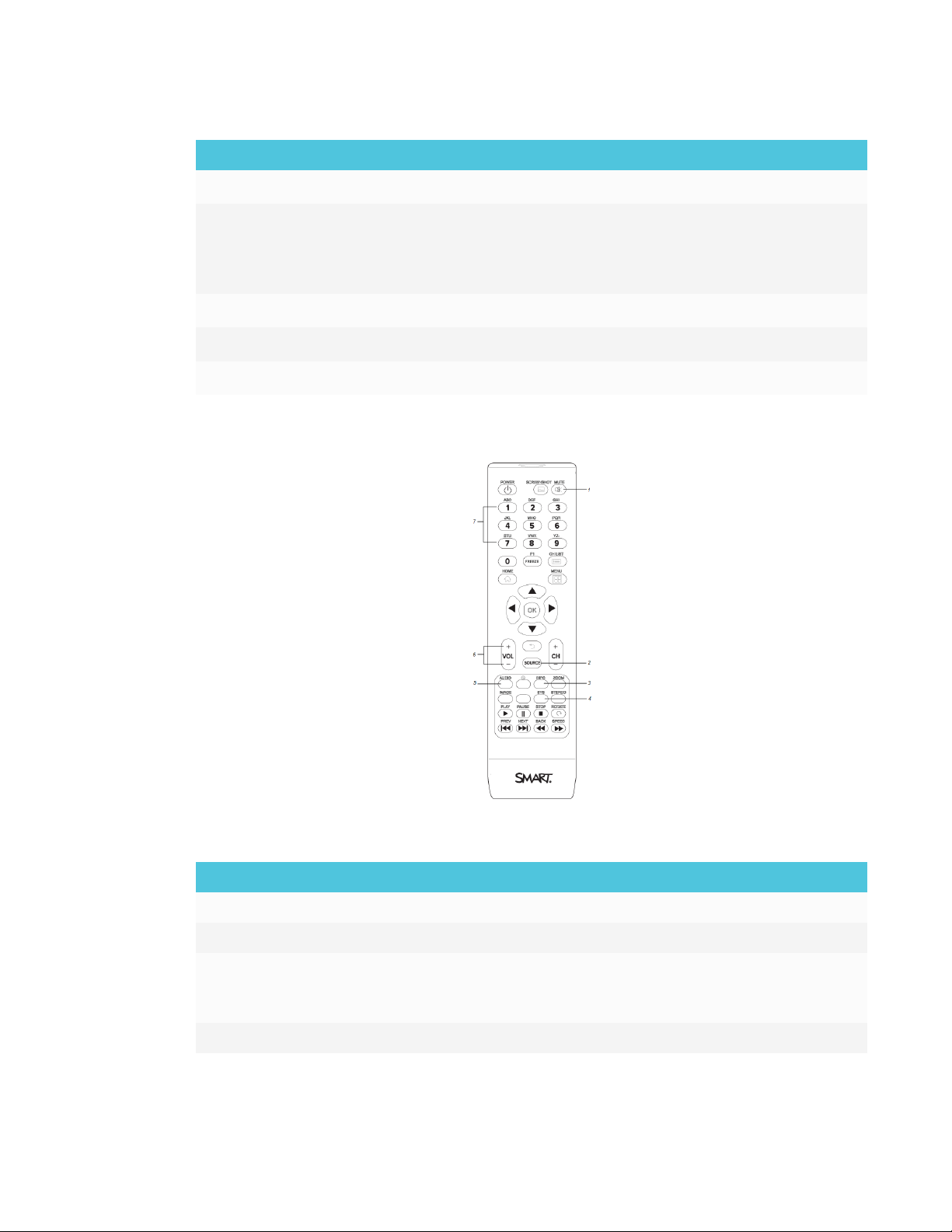
Remote control
Press to freeze and unfreeze the screen.
See SMARTBoard MX series interactive
displays user’s guide
(smarttech.com/kb/171284).
The table below lists the functions available for the remote control.
No. Name Function
1 MUTE Mute or unmute the volume
2 SOURCE Open the input source menu
3 INFO Press to show the display’s detected
resolution and refresh rate for the current
input source
4 SYS Open the display’s settings
6 smarttech.com/kb/171257
Page 19
CHAPTER1
WELCOME
No. Name Function
5 AUDIO Change the display’s audio mode
6 VOL + / VOL - Increase or decrease volume
7 [Number buttons] Press buttons on the number pad to
customize settings
8 POWER Wake the display.
Enter Sleep mode.
Remote control sensor
The status light blinks green and red when it registers a button being pressed on the remote
control.
Status light
The status light blinks green and red when it registers a button being pressed on the remote
control.
When the status light is red, the display is in a low power state. To wake the display, press the
Power button on the front control panel or POWERon the remote control.
Ambient light sensor
The ambient light sensor can detect the room brightness and adjust the display’s brightness. Make
sure Auto is enabled in Brightness and volume in the display’s settings. See Brightness and volume
on page81.
Internal speakers
The display includes two 10 W rms integrated speakers. You can also connect external speakers
(see Connecting external speakers on page25).
Related products
Related products for the display include the following:
l SBA-100 projection audio system
l SMART Audio 400 classroom amplification system
l USB extenders
7 smarttech.com/kb/171257
Page 20
CHAPTER1
WELCOME
SBA-100 projection audio system
The SBA-100 projection audio system consists of two 14 W speakers and is
intended for wall-mounted displays. You can control volume using the
display’s front control panel or the digital volume controls in a connected
computer’s operating system.
For more information, see the SBA-100 projection audio system specifications
(smarttech.com/kb/171146).
SMART Audio 400 classroom amplification system
The SMART Audio 400 classroom amplification system provides high-quality
audio amplification. The system comes with a teacher microphone and optional
student microphone. Multiple speaker options are available, including wall- and
ceiling-mounted speakers. The amplifier receives audio signals from the
microphones and translates them into crystal-clear sound through the speakers.
For more information, see the SMART Audio 400 classroom amplification system specifications
(smarttech.com/kb/171137).
NOTE
The SMARTAudio 400 classroom amplification system is available only in Canada and U.S.
USB extenders
As noted in Connecting cables for room computers, guestlaptops and other input sources on
page23, the USB connection between the display and computer should be no longer than 16'
(5m). If you need to connect a computer that is more than 16' (5 m) from the display, use one of the
following USB extenders:
Extender Specifications
USB-XT smarttech.com/kb/119318
CAT5-XT-1100 smarttech.com/kb/170202
SMARTrecommends only using USBextenders with the USB connectors on the side and bottom
connector panels on the display.
Fore more information, see:
8 smarttech.com/kb/171257
Page 21

CHAPTER1
WELCOME
l Troubleshooting and extending the USB 2.0 and USB 3.0 connection to your SMART
interactive display
l USBcables and connectors
More information
In addition to this guide, SMART provides the following documents for the display:
Document Link
User’s guide smarttech.com/kb/171284
SBID-MX165, MX175, MX186, MX265, MX275 and MX286 installation
smarttech.com/kb/171274
instructions
SBID-MX265 specifications smarttech.com/kb/171240
SBID-MX275 specifications smarttech.com/kb/171259
SBID-MX286 specifications smarttech.com/kb/171260
Comparison smarttech.com/kb/171161
These documents are available in the Support section of the SMART website
(smarttech.com/support). Scan the QR code on the cover of this guide to view the SMARTBoard
MX series interactive displays pages in the Support section.
9 smarttech.com/kb/171257
Page 22

Page 23
Chapter 2
Transporting the display 11
Using transportation aides 12
Accommodating doorways, hallways and elevators 12
Dealing with cracked, chipped or shattered glass 13
Saving the original packaging 13
Installing the display on a wall 13
Choosing a location 14
Choosing a height 16
Assessing the wall 16
Selecting mounting hardware and tools 17
Selecting a wall mount 17
Mounting the display 17
Mounting multiple displays 19
Installing the display on a stand 20
Using SMART mobile stands 20
Using a third-party stand 20
SMART recommends that only trained installers install the display.
This chapter is for installers. Installers should read this information along with the installation
instructions included with the display before they install the display.
WARNING
Improper installation of the display can result in injury and product damage.
Transporting the display
After your organization receives the display, you need to transport it to the place where you plan
to install it.
On occasion, you might also need to move the display to another location after initially installingit.
11 smarttech.com/kb/171257
Page 24
CHAPTER2
INSTALLING THE DISPLAY
IMPORTANT
l Transport the display at your own risk. SMART cannot accept liability for damages or injury
that occur during the display’s transportation.
l When transporting the display, do the following:
o
Follow local safety regulations and standards.
o
Keep the display in its original packaging.
o
Move the display so that its top frame faces up.
o
Have at least two people move the display.
TIP
Display packaging may be labeled to indicate which side is the front. Look for “FRONT” on the
packaging to help orient the box during transportation.
Using transportation aides
You can use the following aides to transport the display:
l Cart
l Furniture dolly
l Mechanical lift
Accommodating doorways, hallways and elevators
In some situations, you might need to remove the display from its packaging to move it through
narrow doorways or hallways or on to an elevator. In these situations, SMART recommends that
you keep the foam pieces on the bottom corners of the display. These foam pieces protect the
display if you need to set it down during transport.
You might also need to rotate the display so that its top frame faces to the side. You can do this
during transportation, but when you install the display, it must be in landscape orientation (with the
top frame facing up).
12 smarttech.com/kb/171257
Page 25
CHAPTER2
INSTALLING THE DISPLAY
Dealing with cracked, chipped or shattered glass
The display contains safety-tempered glass. Although this glass is heat-strengthened to help
withstand impacts, the glass can crack, chip or shatter if struck with enough force. (Safety glass is
designed to break into small pieces rather than sharp shards if it is broken.) Temperature changes
can cause a minor crack or chip to become worse, possibly causing the glass to shatter. See the
knowledge base article, Shattered glass on an interactive display, for information about conditions
that can cause the display’s glass to shatter even when it’s not in use.
If the display’s glass is cracked or chipped, have it professionally inspected and repaired at a
SMART authorized repair center. If the display’s glass shatters, carefully clean up the area and have
the display repaired or replaced.
CAUTION
For safety and to prevent further damage, do not continue to install or use the display if its glass
is cracked, chipped or shattered.
Saving the original packaging
Save the original packaging to repack the display with as much of the original packaging as
possible in case you need to transport the display again after you initially install it. This packaging
was designed to provide the best possible protection against shock and vibration.
CAUTION
Transport the display only in the original packaging or replacement packaging purchased from
your authorized SMART reseller. Transporting the display without correct packaging can lead to
product damage and voids the warranty.
NOTE
If the original packaging isn’t available, you can purchase the same packaging directly from your
authorized SMART reseller (smarttech.com/where).
Installing the display on a wall
Typically, you install the display on a wall in a classroom or meeting space.
13 smarttech.com/kb/171257
Page 26
CHAPTER2
INSTALLING THE DISPLAY
Choosing a location
A display is typically installed at the room’s focal point, such as at the front of a classroom or
meeting space.
Selecting an appropriate location for the display is crucial for ensuring the best possible
experience with the product. Consider the following factors as you choose a location:
Factor Considerations
Room setup
Power and other
connections
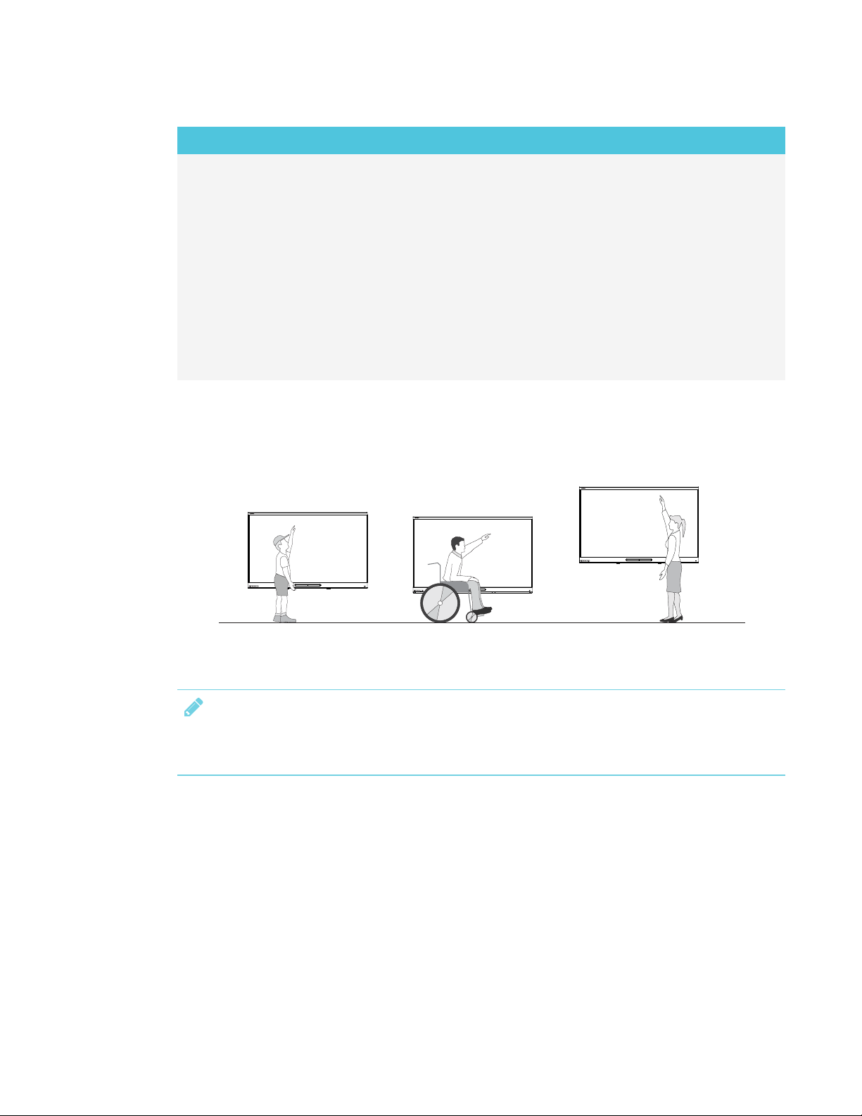
The location allows users, including those in wheelchairs, access to the
l
display.
Refer to local regulations regarding accessibility.
The location allows for multiple users to access the display at a time.
l
The location accommodates room traffic patterns, and there are no
l
tripping hazards.
The display is not installed where it could be hit by a door or gate.
l
There are no nearby shelving units, desks or other furniture that has
l
doors or drawers that could hit the display.
Furniture, wall décor and other room features, such as light switches and
l
thermostats, do not block the display or are blocked by it. (You might be
able to move some of these room features to accommodate the
display.)
The location is close to the following:
l
o
A power outlet
o
A network outlet (if you plan to use a wired network connection)
o
A room computer (if you plan to connect a room computer)
o
Speakers and other devices that you want to connect to the display
NOTES
l
14 smarttech.com/kb/171257
o
If the location is not near a power outlet, consult an electrician for
the power setup you need.
o
Determine if you’ll need additional equipment, such as power
bars, additional cables or cable extenders.
The location is not where the mains power supply enters the building.
Page 27
CHAPTER2
INSTALLING THE DISPLAY
Factor Considerations
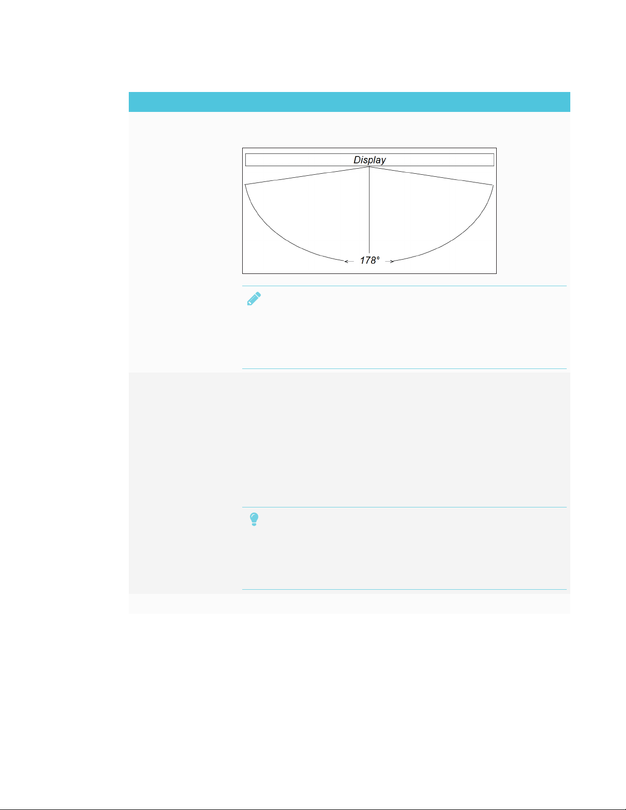
Visibility The display’s screen is clearly visible to all users in the room. SMART
recommends users sit within a 178° viewing area:
NOTE
The viewing area depends on the display’s resolution and a variety of
other factors. For more information, see the knowledge base article,
Recommended viewing distances and viewing angles for
SMARTBoard interactive flat panels.
Lighting The location is not near bright light sources, such as windows or strong
overhead lighting.
Risks of light Interference include:
o
Reduced visibility: Light sources can cause glare on the display’s
screen, reducing its visibility.
o
Touch system interference: Many displays use infrared (IR) light as a
key component of the touch system. Strong light that hits the
display’s screen directly can cause interference with the touch
system and prevent the display from working properly.
TIP
To reduce light interference, install blinds or shades on windows or
skylights and install switches to dim or turn off any lights shining
directly on the display’s screen. Keep in mind that sunlight can come
through windows at different angles at different times of the year.
Acoustics
15 smarttech.com/kb/171257
Page 28
CHAPTER2
INSTALLING THE DISPLAY
Factor Considerations
Environment and
ventilation
The location meets the environmental requirements in the display’s
l
specifications (see More information on page9).
The display isn’t subjected to strong vibrations or dust.
l
Ventilation systems don’t blow air directly on the display.
l
There is adequate ventilation or air conditioning around the display so
l
that heat can flow away from it and the mounting equipment.
SMARTrecommends at least 2" (5 cm) of space on all sides of the
display for proper airflow.
If you plan to install the display in a recessed area, there is at least 4" (10
l
cm) of space between the display and the recessed walls to enable
ventilation and cooling.
Choosing a height
Consider the general height of the user community when you choose the height for the display.
SMART recommends that you mount the display so that its top is 6'5" (1.9m) from the floor.
NOTE
If participants will be sitting at a steep angle (such as in a lecture hall), you may have to adjust the
installation height or angle.
Assessing the wall
Be sure the wall you’re installing the display on can support the weight of the display and mounting
equipment. If the wall can’t support the weight of the display and mounting equipment, consider
using a SMART wall stand to transfer some of the weight from the wall to the floor (see
smarttech.com/accessories).
16 smarttech.com/kb/171257
Page 29

CHAPTER2
INSTALLING THE DISPLAY
NOTE
Refer to the display’s specifications for its weight (see More information on page9).
In some situations, you may need to request an engineering analysis to determine if the wall can
support the display.
Selecting mounting hardware and tools
The mounting hardware and tools required for installation vary according to the type of wall onto
which the display is being mounted.
Refer to the installation instructions for the mounting hardware and tools required for the display.
Selecting a wall mount
It is always best to mount the display on a wall. If the wall can’t support the display’s weight, you
can use additional hardware to transfer some of the weight to the floor.
The display includes a pre-attached wall bracket which can be used to mount the display to the
wall. See the SBID-MX165, MX175, MX186, MX265, MX275 and MX286 installation instructions
(smarttech.com/kb/171274).
Contact your authorized SMART reseller (smarttech.com/where) for information on SMART’s
mounting options.
If you choose a third-party option rather than one of SMART’s mounting options, be sure the wall
mount can support the display’s weight as well as the weight of any attached accessories and can
accommodate the display’s dimensions.
Mounting the display
Mount the display following the included installation instructions. In addition, consider the
following:
The electrical and mechanical components of adisplay are designed to work properly when the
display is mounted in the orientation described in its installation instructions. Mounting the display
in a different orientation can cause malfunctions and will void the display’s warranty.
There are a number of potential hazards of mounting adisplay in a non-standard orientation or
angle:
l Mounting adisplay horizontally (like a table top) can cause the glass to sag, damaging the
display or interfering with the display’s touch system.
17 smarttech.com/kb/171257
Page 30
CHAPTER2
INSTALLING THE DISPLAY
l Non-standard orientation can affect ventilation, creating hotpots in equipment, premature
failures and, in displays that use projectors, exploding projector bulbs.
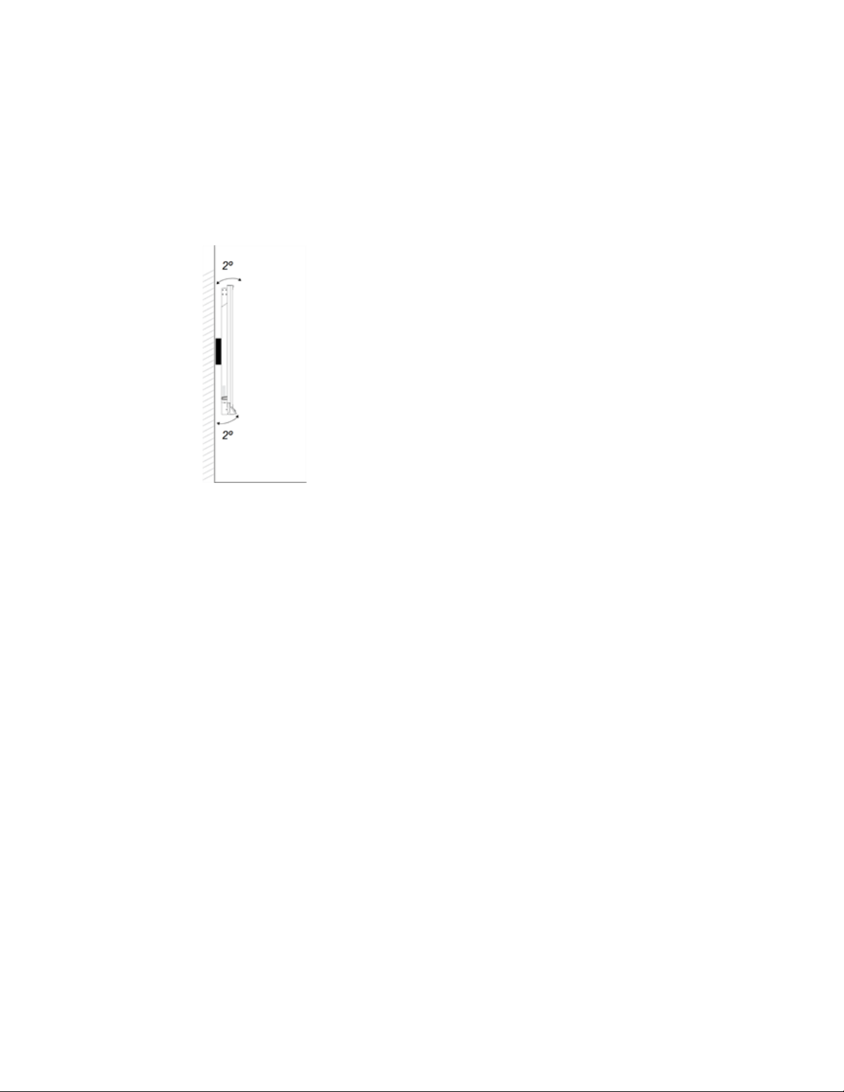
l Mount the display vertically (90° relative to the floor plus or minus 2° for tolerance) and in
landscape orientation. SMART doesn’t support mounting the display at other angles or in
portrait orientation.
18 smarttech.com/kb/171257
Page 31

CHAPTER2
INSTALLING THE DISPLAY
l Use the included wall mount. Optionally, use a VESA-approved mounting plate that is rated for
the display’s weight and size.
l If you’re not using the included bolts to fasten the wall mount to the display, see the following
table.
SMARTBoard
MX265
SMARTBoard
MX275
Minimum
M6
length
Maximum
M6 bolt
length
Fasten
force
Minimum
M8
length
Maximum
M8 bolt
length
Fasten
force
14 mm + x mm
where x is the combined thickness of the wall mount
and washer
18 mm + x mm
where x is the combined thickness of the wall mount
and washer
97.36–177.01 in-lb. (11–20 N·m)
CAUTION
Do not over-tighten the bolts.
18 mm + x mm
where x is the combined thickness of the wall mount
and washer
30 mm + x mm
where x is the combined thickness of the wall
bracket and washer
97.36–177.01 in-lb. (11–20 N·m)
CAUTION
Do not over-tighten the bolts.
SMARTBoard
MX286
Minimum
M8
length
Maximum
M8 bolt
length
Fasten
14 mm + x mm
where x is the combined thickness of the wall mount
and washer
30 mm + x mm
where x is the combined thickness of the wall mount
and washer
97.36–177.01 in-lb. (11–20 N·m)
force
CAUTION
Do not over-tighten the bolts.
Mounting multiple displays
A multiple-display configuration can include two or more displays in a variety of arrangements.
19 smarttech.com/kb/171257
Page 32

CHAPTER2
INSTALLING THE DISPLAY
SMART recommends that you mount no more than three displays in a convex arrangement.
NOTE
Different displays support multiple-display configurations to varying degrees. Consult adisplay’s
documentation before including it in a multiple-display configuration.
Although a computer can support up to 16 touch-sensitive displays, the demands on the computer
and graphics card increase as you add more displays. If you want to use more than three displays,
SMART recommends that you work closely with an experienced installer.
Installing the display on a stand
If you want to move the display from place to place or if it’s not possible to install the display on a
wall, you can install it on a stand.
Using SMART mobile stands
SMART mobile stands are designed for SMART interactive displays. They are height-adjustable.
Some models include integrated speakers, a locking cabinet to secure equipment and casters that
swivel and lock for easy movement.
For more information about SMART mobile stands, see smarttech.com/accessories.
Using a third-party stand
For information on selecting and using a third-party stand, see Installing your SMARTBoard MX on
a stand.
20 smarttech.com/kb/171257
Page 33

Chapter 3
Connecting the iQ appliance 21
Connecting power 22
Connecting to a network 22
Connecting cables for room computers, guestlaptops and other input sources 23
Using recommended cables 23
Connecting to the side connector panel 24
Connecting to the bottom connector panel 24
Connecting to the front connector panel 25
Viewing a connected computer or other device’s input 25
Connecting external speakers 25
Connecting room control systems 26
Connector reference 27
Side connectorpanel 27
Bottom connectorpanel 28
Front connector panel 29
iQ appliance 29
Other connectors 30
Connecting the iQ appliance
For more information about installing the iQ appliance in SMARTBoard MX series interactive
displays, see the SBID-MX165, MX175, MX186, MX265, MX275 and MX286 installation instructions
(smarttech.com/kb/171274).
21 smarttech.com/kb/171257
Page 34

CHAPTER3
CONNECTING POWER AND DEVICES
Connecting power
SBID-MX265 SBID-MX275 SBID-MX286
Connect the supplied power cable from the AC power inlet on the side of the display to a power
outlet.
NOTE
Refer to the display’s specifications for power requirements and power consumption information
(see More information on page9).
Connecting to a network
The display requires a network connection for downloading software
and firmware updates, and a number of the iQ appliance’s apps require
a network connection as well. You can use one of the display’s RJ45
jacks (pictured) to connect to a network, or you can use a Wi-Fi
connection. For more information about the display’s network
connection and configuration, see Connecting the display and iQ
appliance to a network on page33.
You can also connect a computer to the display’s other RJ45 jack so the display and computer are
connected to the same network.
IMPORTANT
Do not use the RJ45 jack on the iQ appliance to connect to a network.
22 smarttech.com/kb/171257
Page 35

CHAPTER3
CONNECTING POWER AND DEVICES
Connecting cables for room computers,
guestlaptops and other input sources
You can connect cables to the display so that users can connect and use room computers, guest
laptops or other devices, such as Blu-ray™ disc players.
NOTE
For information about configuring connected computers, see Chapter 5: Configuring connected
computers on page49.
Using recommended cables
SMART recommends the following varieties of cable:
Cable type Maximum length Recommendation
HDMI 23' (7 m)
VGA 23' (7 m) Use VGA cables with all pins in their connectors fully
Stereo 3.5 mm 20' (6 m) [N/A]
USB 16' (5 m) Use a USB extender if the distance between the
Using cables that exceed these maximum lengths may produce unexpected results, such as
degraded picture quality or degraded USB connectivity.
1
Use only certified HDMI cables that have been
tested to support the performance standard you
require.
populated and wired.
computer and the display is greater than 16' (5 m).
For more information, see USB extenders on page8.
1
The performance of cables longer than 23' (7 m) is highlydependent on the cable’squality.
23 smarttech.com/kb/171257
Page 36

CHAPTER3
CONNECTING POWER AND DEVICES
Connecting to the side connector panel
The side connector panel includes two HDMI video connectors: HDMI 1 and HDMI 2. Both
connectors can accommodate an HDMI cable for video and audio, and both support HDMI 2.0.
NOTES
l The USB Type-B connector for touch control is located on the bottom connector panel. See
Connecting to the bottom connector panel below.
l You can connect a wireless USB keyboard and mouse to the two USB Type-A connectors.
Connecting to the bottom connector panel
The bottom connector panel includes a video connector and USBconnector:
l VGA: This connector can accommodate a VGA cable for video.
l USBType-B: This connector can accommodate a USB cable for touch control for computers
connected to HDMI 1, HDMI 2 or VGA.
24 smarttech.com/kb/171257
Page 37

CHAPTER3
CONNECTING POWER AND DEVICES
NOTE
When connecting a computer to the VGA connector, use the Stereo 3.5 mm in connector for
audio.
Connecting to the front connector panel
In addition to the three sets of video connectors on the side and
bottom connector panel, there is one set of computer
connectors on the front control panel:
l HDMI 3: This set of connectors can accommodate a
USBcable for touch control and an HDMI cable for video
and audio. This input supports HDMI1.4 with HDCP1.4.
l USBType-B: This connector can accommodate a USB
cable for touch control for computers connected to HDMI
3.
Viewing a connected computer or other device’s input
Users can tap the Input button to open the input selection menu. Tap an input source to view the
computer or other device’s input on the display.
For information about viewing a connecteds device’s input, see the SMARTBoard MX series
interactive display user’s guide (smarttech.com/kb/171284).
Connecting external speakers
The display includes two 10 W speakers, which are designed to provide sound at the front of a
room. You can connect external active speakers if you’re providing sound in a larger space. See
SMART Audio 400 classroom amplification system on page8 for more information.
You can connect external speakers to the display using the stereo
3.5mm out connector (pictured).
25 smarttech.com/kb/171257
Page 38

CHAPTER3
CONNECTING POWER AND DEVICES
The display also provides a Sony/Philips Digital Interface (S/PDIF)
optical out connector. S/PDIF is a digital audio transmission medium.
You need an audio receiver that supports S/PDIF to decode this
connection to analog for use with external speakers.
Connecting room control systems
A room control system enables users to control a room’s lighting, audio system and, possibly, the
display. Some installations may require you to integrate the display with a room control system.
Refer to the display’s documentation to see if it works with an external room control system.
You can use the display’s RS-232 connector to connect a third-party external control system to the
display (see Appendix C: Remotely managing the display on page85).
NOTE
Displays are not compatible with centralized remote control systems, such as a universal remote
control.
26 smarttech.com/kb/171257
Page 39

CHAPTER3
CONNECTING POWER AND DEVICES
Connector reference
Side connectorpanel
The following diagram and table present the connectors on the display’s connector panel:
No. Connector Connects to Notes
1 HDMI 1.4 out (HDCP-
compliant)
27 smarttech.com/kb/171257
External monitor This connector is HDCP-
encrypted HDMI.
HDMIout is an optional
feature. Contact your
authorized SMART reseller
(smarttech.com/where) for
further ordering instructions.
NOTE
Page 40

CHAPTER3
CONNECTING POWER AND DEVICES
No. Connector Connects to Notes
2 USB Type-A
connector
USB drives and other
devices
Connect a USBdrive to update
the display’s firmware.
NOTE
If troubleshooting an issue
with the display, connect a
USB mouse to navigate the
display’s on-screen menu.
3 USB Type-A
connector
USB drives and other
devices
Connect USB drives and other
devices that you want to use
with the currently selected input
source.
4 HDMI 1 2.0 in HDMI 1 input
See page23.
(videoandaudio)
5 HDMI 2 2.0 in HDMI 2 input
See page23.
(videoandaudio)
6 RJ45 (×2) Network See page22.
Bottom connectorpanel
The following diagram and table present the connectors on the display’s bottom connector panel:
No. Connector Connects to Notes
1 USB Type-B HDMI 1, HDMI 2 or VGA
input (touch)
2 RS-232 Room control system See page85.
3 Stereo 3.5 mm out External speakers or audio
system
4 S/PDIF out Optical digital audio output See page25.
5 Stereo 3.5 mm in VGA input (audio) See page23.
6 VGA in VGA input (video) See page23.
See page23.
See page25.
28 smarttech.com/kb/171257
Page 41

CHAPTER3
CONNECTING POWER AND DEVICES
Front connector panel
The following diagram and table present the connectors on the display’s convenience panel:
No. Name Procedure
1 USB Type-A connector Connect USB drives and other devices that
you want to use with the currently selected
input source.
2 USB Type-A connector Connect a USBdrive to update the display’s
firmware.
3 USB Type-B connector
4 HDMI 3 input connector Connect a computer or other input source to
Connect a USB cable to the display and
computer to provide touch control of the
computer connected to HDMI 3.
the display (see page23).
iQ appliance
The following diagram and table present the connectors on the iQ appliance:
29 smarttech.com/kb/171257
Page 42

CHAPTER3
CONNECTING POWER AND DEVICES
No. Connector Connects to Notes
1 RJ45 [N/A] Do not use this connector. Use
the connectors on the display
instead. See page22.
2 USB Type-A (×2) [N/A] Do not use. See page29.
3 HDMI out [N/A] Do not use. See page27.
5 Micro SD [N/A] This connector is a service port.
6 LED [N/A] LED lights green when the iQ
appliance is inserted in the
accessory slot and turned on.
Other connectors
There are additional connectors on the bottom of the display (see Mounting multiple displays on
page19 and Appendix C: Remotely managing the display on page85).
30 smarttech.com/kb/171257
Page 43

Chapter 4
Turning on the display for the first time 32
Turning on and setting up the display for the first time 32
Connecting the display and iQ appliance to a network 33
Configuring the iQ appliance’s network connection 33
Connecting the iQ appliance to a network 37
Connecting the display to a network 39
Evaluating the impact of Screen Share on your network data usage 40
Updating system software 40
Updating iQ system software 40
About iQ system software 41
Applying an automatic iQ system software update manually 41
Updating system software manually 41
Updating the display’s firmware 41
About firmware updates 41
Applying the display’s firmware update manually 42
Updating system software manually 42
Locking down the Settings app for iQ system software 43
Creating a new lockdown certificate 43
Locking down the iQ appliance with an existing lockdown certificate 44
Unlocking the iQ appliance with an existing lockdown certificate 44
Switching the iQ system software to the Beta channel 44
Before switching to the Beta channel 45
Switching between the Beta and Stable channels 45
Getting support and sending feedback 46
Adding or removing apps from the launcher 47
Selecting which apps appear in the launcher 47
Enabling the Whiteboard Library 47
After you have mounted the display and connected power and devices, you can start it for the first
time and configure the apps as described in this chapter.
31 smarttech.com/kb/171257
Page 44

CHAPTER4
CONFIGURING THE DISPLAY
Turning on the display for the first time
Turn on the display after mounting it and connecting power and devices.
Turning on and setting up the display for the first time
To turn on and set up the display for the first time
1. Turn on the display by flicking the power switch on the back of the display.
SBID-MX265 SBID-MX275 SBID-MX286
2. Select your preferred language, and then tap Next.
3. Select your country, and then tap Next.
4. Select your time zone, and then tap Next.
5. Set the date, and then tap Next.
6. Set the time, and then tap Next.
7. Name the display, and then tap Next.
8. If the display isn’t using a wired network connection, select a wireless network, and then tap
Next.
9. Select the list of applications that will appear in the launcher, and then tap Next. For more
information about the apps, see the SMARTBoard MX series interactive displays user’s guide
(smarttech.com/kb/171284).
10. Select the apps you want to appear in the launcher, and then tap Next.
TIP
To change which apps appear in the launcher, see Adding or removing apps from the
launcher on page47.
11. Tap Finish.
The Welcome screen appears.
12. To ensure updates to the display’s firmware, connect the display to a network with Internet
access. See Connecting the display to a network on page39.
32 smarttech.com/kb/171257
Page 45

CHAPTER4
CONFIGURING THE DISPLAY
Connecting the display and iQ appliance to a network
You can connect the display and iQ appliance to a network using a Wi-Fi connection. If the display
is connected to a network using an Ethernet connection, the iQ appliance will also be connected
to the network. Before you do so, your organization’s network administrators need to configure the
network for the display.
Configuring the iQ appliance’s network connection
IMPORTANT
Configuring the network properly allows the iQ appliance to download important iQ system
software and feature updates automatically.
33 smarttech.com/kb/171257
Page 46

CHAPTER4
CONFIGURING THE DISPLAY
Network administrators need to configure the network so users can use the Screen Share app,
update the system software automatically over the air and enable the iQ appliance to set the date
and time automatically.
34 smarttech.com/kb/171257
Page 47

CHAPTER4
CONFIGURING THE DISPLAY
To configure the network
Add the following URLs to the network whitelist.
URL Feature
https://ws.kappboard.com
Automatic iQ system software
update
NOTE
Block access to https://ws.kappboard.com to
prevent automatic iQ system software updates
https://*.mixpanel.com iQ system software
*.hockeyapp.net iQ system software
https://*.smarttech-prod.com SMARTNotebook® Player
http://*.loggly.com SMARTNotebook Player
http://*.smarttech.com iQ system software,
SMARTNotebook Player,
SMARTamp
https://*.smarttech.com SMARTNotebook Player
https://www.fabric.io/ SMARTNotebook Player
https://*.classlab.com SMARTNotebook Player,
SMARTamp
https://www.firebase.com/test.html SMARTNotebook Player,
SMARTamp
https://*.smartamp.com SMARTNotebook Player,
SMARTamp
https://*.google.com SMARTNotebook Player
http://*.google-analytics.com SMARTNotebook Player
https://www.gstatic.com SMARTNotebook Player
https://*.firebaseio.com SMARTNotebook Player
https://*.cloudfront.com SMARTNotebook Player
https://content.googleapis.com SMARTamp
https://gstatic.com SMARTamp
https://*.youtube.com SMARTNotebook Player,
SMARTamp
https://api.datamarket.azure.com SMARTamp
https://updates.airsquirrels.com Screen Share app
35 smarttech.com/kb/171257
Page 48

CHAPTER4
CONFIGURING THE DISPLAY
To allow mobile devices and computers to use AirPlay and Google Cast to use the Screen Share
app
1. Open the required TCP/UDP ports:
Protocol Port range Feature
TCP 80 e³ experience system
software update
Outbound http
TCP 80 Outbound http
UDP 123 Network Time Protocol
TCP 3689 iTunes music sharing
TCP 5000 Audio streaming
TCP 5353 mDNS
UDP 5353 mDNS
TCP 7000 Picture sharing
TCP 7001 Video streaming
UDP 7010 Display mirroring
UDP 7011 Display mirroring
TCP 7100 Display mirroring
TCP 47000 Audio negotiation
TCP 49152–65535 Dynamic ports
UDP 49152–65535 Dynamic ports
TCP 49228 Google Cast
TCP 50259 Google Cast
UDP 54780 Google Cast
UDP 62572 Google Cast
2. Configure the network to allow Bonjour and mDNS (multicast).
3. Configure the network to allow Network Time Protocol (NTP) requests to Internet time servers.
NOTE
Using a 5 GHz wireless network connection may provide a better experience with the
Screen Share app.
36 smarttech.com/kb/171257
Page 49

CHAPTER4
CONFIGURING THE DISPLAY
To allow SMARTNotebook Player to connect to the display
NOTE
The network may have been configured to allow Network Time Protocol in To allow mobile
devices and computers to use AirPlay and Google Cast to use the Screen Share app.
Configure the network to allow Network Time Protocol (NTP) requests to Internet time servers
To allow updates to the display’s firmware
Open TCP port 80.
Connecting the iQ appliance to a network
The iQ appliance can connect to a network using either Wi-Fi or use the display’s Ethernet
connection. Network administrators can also add a browser proxy or install a certificate.
To connect to a Wi-Fi network
Tap the Home button on the screen.
1.
The launcher appears.
Tap Settings .
2.
The Settings window appears.
3. Tap Wi-Fi.
NOTE
Ensure Wi-Fi is turned On.
4. Select a wireless network.
If the Wi-Fi network is not password protected, the display connects to the network.
5. If the network requires a password, enter the Wi-Fi password and tap Connect.
OR
If the network requires a user name and password, enter the user name and Wi-Fi password
and tap Connect.
TIP
Use the crosshairs to move the on-screen keyboard.
37 smarttech.com/kb/171257
Page 50

CHAPTER4
CONFIGURING THE DISPLAY
To connect to an Ethernet network
Connect an Ethernet cable to the RJ45 receptacle on the display.
NOTE
The network must provide network settings via DHCP. If you require a static IP, use DHCP
reservation on your router.
To configure a proxy
Tap the Home button on the screen.
1.
The launcher appears.
Tap Settings .
2.
The Settings window appears.
3. Tap Wi-Fi.
4. Tap and hold the network to which you’re adding a proxy.
A dialog box appears.
5. Tap Modify network.
6. Select Show advanced options.
7. In the Proxy box, select Manual.
8. Enter the information in the Proxy hostname, Proxy port and Bypass proxy boxes.
9. Tap Save.
To install a certificate
NOTE
Certificates must be PFX format.
1. Copy a PFX format certificate to a USB drive.
Tap the Home button on the screen.
2.
The launcher appears.
Tap Settings .
3.
The Settings window appears.
38 smarttech.com/kb/171257
Page 51

CHAPTER4
CONFIGURING THE DISPLAY
4. Tap Wi-Fi > … > Advanced > Install Certificates.
The USBDrive window appears.
5. Tap USB Drive.
6. Select a certificate to install.
7. If required, enter a password to extract the certificate.
8. Optionally, enter a name for the certificate in the Certificate name box and reason for
certificate use in the Credential use box. Tap OK.
A window appears requesting that a lock screen PIN, pattern or password be set before using
the certificate.
9. Tap OK.
10. Select a pattern, PIN or password method. Tap OK.
IMPORTANT
Make note of the pattern, PIN or password. The pattern, PIN or password may be required to
install future certificates.
If the pattern, PIN or password is forgotten, a factory reset is required before installing more
certificates.
The iQ system software confirms the certificate was installed.
Connecting the display to a network
To connect to a Wi-Fi network
Tap the Menu button on the front control panel.
1.
The display’s settings appear.
2. Tap Network.
3. Ensure Wi-Fi is enabled and Ethernet is disabled.
4. Select a wireless network.
If the Wi-Fi network is not password protected, the display connects to the network.
39 smarttech.com/kb/171257
Page 52

CHAPTER4
CONFIGURING THE DISPLAY
5. If the network requires a password, enter the Wi-Fi password and tap Connect.
OR
If the network requires a user name and password, enter the user name and Wi-Fi password
and tap Connect.
To connect to an Ethernet network
1. Connect an Ethernet cable to the RJ45 receptacle on the display.
2. Tap Settings.
3. Tap Network.
4. Ensure Ethernet is enabled and Wi-Fi is disabled.
Evaluating the impact of Screen Share on your network data usage
When you connect your device or computer to the display using Screen Share, the screen sharing
protocol compresses the image from your device or computer. The protocol may transmit only
areas of the screen that change. This can make it difficult to estimate the impact of Screen Share
on a network where many users would like to screen share simultaneously.
For example, in a school where 30 teachers are using Screen Share simultaneously, 10% of
teachers might be streaming video while 90% might be sharing static content with occasional
updates. In such an instance, you could expect to see an additional 5 Mbps in network traffic. Use
the following table to help estimate the impact of wireless Screen Share on your network.
Content being shared Data rate transmission
Static content with minor screen movement 20 kbps
Static content with periodic scrolling or
refreshes
Gaming or streaming video with major screen
changes
Spikes briefly to 500–600 kbps, returns to 20
kbps
700 kb/sec–1.2 Mbps
Updating system software
Updating iQ system software
When the iQ appliance is connected to the Internet, it updates its system software automatically.
40 smarttech.com/kb/171257
Page 53

CHAPTER4
CONFIGURING THE DISPLAY
About iQ system software
When a system software update is available, the iQ appliance downloads the update in the
background then waits for four hours of inactivity. When that happens, the display shows a
two-minute countdown before beginning the update. The countdown can be interrupted at any
time. The update begins when the countdown finishes. The display shows a blank screen for four
minutes. When the update is complete, the display shows the Whiteboard and any content that
was on Whiteboard before the update.
When the update is installing, touch, the front control panel and remote control will not respond.
NOTE
You can configure your organization’s network to allow or prevent automatic system software
updates (see Configuring the iQ appliance’s network connection on page33).
Applying an automatic iQ system software update manually
If the iQ appliance has downloaded the system software update but hasn’t yet applied the update,
you can start the update process manually from Settings.
To apply an automatic iQ system software update manually
Tap the Home button on the screen.
1.
The launcher appears.
Tap Settings .
2.
The Settings window appears.
3. Scroll to Auto Update.
4. Under Check for Updates Now, tap Apply Update Now.
Updating system software manually
You can download system software updates at smarttech.com/downloads and update your display
using a USB drive.
Updating the display’s firmware
When the display is connected to the Internet, it updates its firmware automatically.
About firmware updates
When a display is connected to the Internet and an update for the display’s firmware is available,
41 smarttech.com/kb/171257
Page 54

CHAPTER4
CONFIGURING THE DISPLAY
the display shows a message that an update is available.
When the update is installing, touch, the front control panel and remote control will not respond.
Applying the display’s firmware update manually
To apply a system software update
1. A dialog box appears on the screen asking if you want to update the display’s firmware.
2. Tap Update to update the display’s firmware.
OR
Tap Cancel to update the display’s firmware at a later time.
To apply an automatic system software update manually
On the display, press the Menu button on the front control panel.
1.
2. Tap Update.
3. Under Update, tap Update.
Updating system software manually
You can download system software updates at smarttech.com/downloads and update your display
using a USB drive.
1. Go to smarttech.com/downloads and download the update file for your size of display.
2. Copy the .zip file to a USB drive.
3. Insert the USB drive into the display USB.
Press Menu on the front control panel to open the display’s settings.
4.
5. Tap Update.
6. Tap Check.
A dialog box appears.
7. Tap USB.
42 smarttech.com/kb/171257
Page 55

CHAPTER4
CONFIGURING THE DISPLAY
8. The upgrading software screen appears.
If the update includes an upgrade to the touch firmware, don’t touch the screen during an
update.
9. Using the switch on the back of the display, turn off the display.
10. Wait 10 seconds.
11. Using the switch on the back of the display, turn on the display.
Locking down the Settings app for iQ system software
Administrators can limit access to the iQ experience’s Settings app by a lockdown certificate
saved on a USB drive.
NOTE
This limits access to the settings for the iQ appliance. It does not limit access to the
SMARTBoard MX interactive display’s settings.
Creating a new lockdown certificate
CAUTION
If the lockdown certificate is lost while the display’s Settings app is locked down, you’ll have to
perform a factory reset to regain access to the Settings app. See Factory Reset on page77
TIP
Make a backup of the lockdown certificate to ensure you still have access to it in case the
original is lost.
To lock down settings
1. Insert a USB drive into the display.
This is a snippet
2. Open the launcher.
Tap Settings .
3.
43 smarttech.com/kb/171257
Page 56

CHAPTER4
CONFIGURING THE DISPLAY
4. Tap Security > Lock Down Settings.
5. Use the on-screen keyboard to enter a name for the lockdown certificate, and then tap
Create.
The display’s settings are locked down.
6. Remove the USB drive and keep it in safe place.
Locking down the iQ appliance with an existing lockdown certificate
If you’ve already created a lockdown certificate, you can use it to lock the Settings app.
To lock down the iQ appliance with an existing lockdown certificate
1. Insert a USB drive with the lockdown certificate on it into the display.
This is a snippet
2. Open the launcher.
Tap Settings .
3.
4. Tap Lock Down Settings.
The settings are locked down.
Unlocking the iQ appliance with an existing lockdown certificate
If you’ve locked down the Settings app with a lockdown certificate, you can use the lockdown
certificate to unlock the Settings app.
1. Insert a USB drive with the certificate on it into the display.
This is a snippet
2. Open the launcher.
Tap Settings .
3.
4. Tap Unlock Settings.
The iQ appliances’s settings are available.
Switching the iQ system software to the Beta channel
The Beta channel for the iQ system software is meant for advanced users who are comfortable
using pre-release software. System software releases in the Beta channel contain new features
44 smarttech.com/kb/171257
Page 57

CHAPTER4
CONFIGURING THE DISPLAY
that are still in development.
Sign up to receive Beta channel announcements at smarttech.com/SMARTBetaProgram or go to
smarttech.uservoice.com to learn more about upcoming Beta releases.
IMPORTANT
l You may encounter bugs or other unexpected behavior in pre-release software.
l Features previewed in the Beta channel may never appear in a Stable channel release.
l There may be frequent updates to the iQ system software.
l The user interface may change significantly as features develop.
l If you switch to the Beta channel and want to return to the Stable channel, you must perform
a factory reset that erases all of the iQ system software settings.
Before switching to the Beta channel
Before switching to the Beta channel, back up important Whiteboard content using the
SMARTkapp® app. See the SMARTBoard MX series interactive displays user’s guide
(smarttech.com/kb/171284).
Switching between the Beta and Stable channels
To switch to the Beta channel
Tap the Home button on the screen.
1.
The launcher appears.
Tap Settings .
2.
The Settings window appears.
3. Tap Auto Update.
4. Tap Update Channel, and then select Beta Channel.
A dialog box appears asking you to confirm the switch to the beta system software releases.
The display checks for a Beta system software update.
45 smarttech.com/kb/171257
Page 58

CHAPTER4
CONFIGURING THE DISPLAY
To switch to the Stable channel
Tap the Home button on the screen.
1.
The launcher appears.
Tap Settings .
2.
The Settings window appears.
3. Tap Auto Update.
4. Tap Update Channel, and then select Stable Channel.
A dialog box appears asking you to confirm the switch to the Stable channel system software
releases.
The display checks for a Stable channel system software update.
5. Tap Ready to apply update.
Getting support and sending feedback
SMART Support will not be able to help you resolve problems you may encounter in Beta channel
releases.
SMART appreciates your willingness to use Beta channel releases and values all types of
feedback.
l Report issues with Beta channel releases at smarttech.uservoice.com.
l Provide feedback to SMART about new features at smarttech.uservoice.com.
l Suggest new features to SMART at smarttech.uservoice.com.
46 smarttech.com/kb/171257
Page 59

CHAPTER4
CONFIGURING THE DISPLAY
Adding or removing apps from the launcher
You can add or remove apps from the launcher.
Selecting which apps appear in the launcher
To add or remove apps from the launcher
Tap the Home button on the screen.
1.
The launcher appears.
Tap Settings .
2.
The Settings window appears.
3. Tap Launcher.
4. Select the apps you want to include in the launcher.
OR
Clear the check boxes for apps you want to remove from the launcher.
Enabling the Whiteboard Library
The display saves Whiteboard sessions to the Library. The Library is disabled on some displays
and must be enabled if you want to save Whiteboard sessions or continue previous sessions.
To enable the Library
Tap the Home button on the screen.
1.
The launcher appears.
Tap Settings .
2.
The Settings window appears.
Tap Applications, and then tap Whiteboard .
3.
4. Switch the Library option ON.
47 smarttech.com/kb/171257
Page 60

Page 61

Chapter 5
Installing SMART software on connected computers 49
Installing SMART Learning Suite 49
Installing SMART Product Drivers 50
Setting connected computers’ resolutions and refresh rates 50
Install SMARTsoftware and set the resolution and refresh rate on any computers you connect to
the display.
NOTE
For information about connecting computers, see Connecting cables for room computers,
guestlaptops and other input sources on page23.
Installing SMART software on connected computers
To take full advantage of the SMART Board display's features, install SMART Learning Suite and
SMART Product Drivers on computers you connect to the display.
Installing SMART Learning Suite
All models come with one license of SMART LearningSuite. You can download SMART
LearningSuite from smarttech.com/downloads and install it on a room computer.
You can purchase additional licenses of SMARTLearning Suite to install on other computers.
Contact your authorized SMART reseller (smarttech.com/where) for more information.
IMPORTANT
Make sure a computer meets the minimum requirements in the SMARTNotebook software
release notes before you install SMART Learning Suite.
49 smarttech.com/kb/171257
Page 62

CHAPTER5
CONFIGURING CONNECTED COMPUTERS
Installing SMART Product Drivers
SMARTBoard MX series interactive displays require SMARTProduct Drivers 12.10 or later installed
on the room computer. If you’ve installed SMARTLearning Suite 17.1 or earlier, you’ll need
download a newer version of SMARTProduct Drivers from smarttech.com/downloads.
Setting connected computers’ resolutions and refresh rates
The following table presents the recommend resolutions and refresh rates for the display’s input
sources:
Input source Resolution Refresh rate
HDMI 1 and HDMI 2 3840×2160 60Hz
HDMI 3 (with 1920×1080 60Hz
VGA 1920×1080 60Hz
If possible, set connected computers to these resolutions and refresh rates. See the connected
computers’ operating system documentation for instructions.
For more information, see Appendix E: Supported resolutions on page95.
50 smarttech.com/kb/171257
Page 63

Chapter 6
Checking the display installation 51
Cleaning the screen 51
Cleaning the touch sensors 52
Maintaining ventilation 53
Preventing condensation 53
Replacing the pens 53
Turning the display off and back on 53
Resetting the display 54
Removing and transporting the display 54
With proper maintenance, the display will provide years of use.
Checking the display installation
Inspect the display installation frequently to ensure that it remains securely installed.
l Check the mounting location for signs of damage or weakness that can occur over time.
l Check for loose screws, gaps, distortions or other issues that could occur with the mounting
hardware.
If you find an issue, contact a trained installer.
Cleaning the screen
Follow these instructions to clean the screen without damaging its anti-glare coating or other
product components.
CAUTION
l Do not use permanent or dry-erase markers on the screen. If dry-erase markers are used on
the screen, remove the ink as soon as possible with a lint-free, non-abrasive cloth.
l Do not rub the screen with dense or rough material.
l Do not apply pressure to the screen.
51 smarttech.com/kb/171257
Page 64

CHAPTER6
MAINTAINING THE DISPLAY
l Do not use cleaning solutions or glass cleaners on the screen, because they can deteriorate
or discolor the screen.
To clean the screen
1. Turn off any connected computers.
2. Turn off the display (see Turning the display off and back on on the facing page).
3. Wipe the screen with a lint-free, non-abrasive cloth.
NOTE
Alternatively, you can use a damp cloth with a drop of dish soap.
Cleaning the touch sensors
The display uses infrared (IR) transmitters and sensors around the display’s perimeter between the
screen and the frame. Dust buildup on the protective plastic can impair touch performance. Inspect
these areas for dust and clean them every week.
CAUTION
l Do not use compressed air to clean the sensors or borders.
l Do not use water or cleaning agents to clean the touch sensors.
l Do not apply too much pressure when cleaning the display because you can damage the
plastic.
To clean the IR transmitters and sensors
1. With a clean lint-free, non-abrasive cloth, gently wipe the plastic between the screen and the
frame around the perimeter of the display’s screen.
2. If dirt still remains, use 50% isopropyl alcohol (IPS) to clean the protective plastic between the
screen and the frame.
52 smarttech.com/kb/171257
Page 65

CHAPTER6
MAINTAINING THE DISPLAY
Maintaining ventilation
The display requires proper ventilation. Dust buildup in the ventilation holes compromises cooling
and can lead to product failure.
l Clean accessible ventilation holes monthly with a dry cloth.
l Use a vacuum cleaner with a narrow hose end fitting to clear the back ventilation holes
regularly. You might have to remove the display from the wall.
For more information on removing the display, see Removing and transporting the display on
the next page.
CAUTION
Avoid setting up or using the display in an area with excessive levels of dust, humidity or smoke.
Preventing condensation
If the display has been moved from a colder environment to a warmer environment (for example,
from storage to the installation site), let the display sit for a few hours so that it can acclimate to the
new temperature. Failing to do so can cause humidity to build up in the space between the front
glass and the LCD.
If condensation appears under the screen after you turn on the display, select an active video
source and leave the display on for 48 hours. If the condensation doesn’t dissipate, contact SMART
Support if the display is still under warranty.
If there is enough moisture between the layers to cause the moisture to drip and run, remove
power immediately and contact SMART Support if the display is still under warranty.
Replacing the pens
To prevent damage to the display’s anti-glare coating, replace a pen if its nib becomes worn. You
can purchase replacement pens from the Store for SMART Parts
(seesmarttech.com/Support/PartsStore).
Turning the display off and back on
In most situations, you can put the display to sleep when not using it following the instructions in the
SMARTBoard MX series interactive displays user’s guide (smarttech.com/kb/171284).
53 smarttech.com/kb/171257
Page 66

CHAPTER6
MAINTAINING THE DISPLAY
In some situations, such as when you need to transport the display or clean its screen, you need to
turn the display off for a period of time. You can turn it back on after.
To turn the display off
Press and hold the Power button on the front control panel for two seconds.
1.
To turn the display back on
Press the Power button on the front control panel.
Resetting the display
You can reset the display and the iQ appliance using the switch on the back of the panel.
To perform a factory reset, see Restore factory settings on page82. A factory reset returns all
options to their default values.
To reset the display
1. Flick the switch to the OFF (O) position.
2. Flick the switch to the ON (|) position.
The display and iQ appliance reset.
Removing and transporting the display
If the display is wall mounted, you might need to remove it from its current location and transport it
to another location on occasion.
To remove the display safely, use two or more trained installers.
WARNING
l Do not attempt to move the display by yourself. The display is very heavy.
l Do not move the display by connecting a rope or wire to the handles on the back. The
display can fall and cause injury and product damage.
54 smarttech.com/kb/171257
Page 67

CHAPTER6
MAINTAINING THE DISPLAY
IMPORTANT
Follow any documentation included with the third-party mounting hardware.
To remove the display
1. Turn off connected computers.
Turn off the display by pressing and holding the Power button on the front control panel for
2.
two seconds.
3. Flick the switch on the back of the display to the OFF(O) position.
4. Remove all accessible cables, connectors and antennae.
5. Remove the iQ appliance from the accessory slot.
6. Lift the display from its mounting location and insert it into its original shipping box.
WARNING
Do not place the display on a sloping or unstable cart, stand or table. The display could fall,
resulting in injury and severe product damage.
CAUTION
Do not leave the display face up, face down or upside down for an extended period. This
could cause permanent damage to the screen.
7. Remove the mounting brackets.
To transport the display
See Transporting the display on page11.
55 smarttech.com/kb/171257
Page 68

Page 69

Chapter 7
Troubleshooting the display 57
Resolving general issues 58
Resolving issues with power 58
Resolving issues with image or video quality 59
Resolving issues with audio 61
Resolving issues with touch and digital ink 62
Troubleshooting the iQ system software 62
Resolving general issues 63
Resolving issues with SMARTNotebook Player 64
Resolving issues with Browser 65
Resolving issues with Screen Share 65
Resolving issues with Android mobile devices 66
Resolving issues with Apple devices 67
Resolving issues with Chrome browser and Chromebook 68
Resolving issues with Windows computers 70
Advanced troubleshooting for Screen Share 72
Referring to the SMART knowledge base for additional troubleshooting information 73
Contacting your reseller for additional support 73
Locating the display’s serial number 73
Locating the iQ appliance serial number 73
This chapter explains how to troubleshoot issues with the display and its software.
Troubleshooting the display
The following information helps you resolve a variety of common issues with the display, including
issues with:
l Power
l Video
l Image quality
57 smarttech.com/kb/171257
Page 70

CHAPTER7
TROUBLESHOOTING
l Audio
l Touch and digital ink
Resolving general issues
Issue Solutions
You’ve forgotten the lock screen
Contact SMARTSupport.
password.
You forgot the Settings security
Contact SMARTSupport.
password.
The display can’t connect to a
5GHz wireless network.
The wireless network may be operating on bands that the display doesn’t
support.
Contact your networkadministrator.
Resolving issues with power
Issue Solutions
The display doesn’t turn on and its
power light isn’t lit.
The display turns on but nothing
shows on the screen.
l Make sure the power cable is securely fastened to the power outlet and the
display.
If the power cable is plugged into a power bar, make sure the power bar is
securely fastened to the power outlet and turned on.
l Make sure the switch on the back of the display is in the ON (I) position.
l Make sure the power outlet is workingby testingit with a different device.
l Make sure the power cable is working by testing it with a different device.
l Press the Power button to wake the display.
The status light is red when the display is in a low power state.
NOTE
NOTE
The display doesn’t turn on when
you use a connected computer’s
mouse or keyboard.
You’re experiencing other issues
with power, or the previous
solutions don’t resolvethe issue.
58 smarttech.com/kb/171257
l If the status light is solid green, see Resolving issues with image or video quality
on the facing page.
l Restart the display.
See Tur ning the display off and back on on page53.
l Make sure the computer is on.
l If the status light is red, press the display’s Power button to wake the display.
See Referr ing to the SMART knowledge base for additionaltr oubleshooting
information on page73.
Page 71

CHAPTER7
TROUBLESHOOTING
Resolving issues with image or video quality
Issue Solutions
You’re experiencing the following
or similar issues with image quality:
l There are lines or snow on
the screen.
l The image is flickeringor
flashing.
You’re experiencing the following
or similar issues with video:
l The videois distorted.
l There is visual noise.
l The image is dim.
l Set the connected computer’s resolution and refresh rates to values that the
display supports.
See Setting connected computers’ resolutions and r efresh rates on page50.
l Open the on-screen display menu. If it appears correctly,the issue is with the
videoinput.
l Restart the display.
See Tur ning the display off and back on on page53.
l Make sure the cable is not longer than the maximum specified in the display’s
specifications.
l Make sure the cable is securely connectedto the videoconnectors on the
display and the computer.
l If the video connection uses and extender or goes through a wall socket,try
connecting the display and computer directly.
l Make sure any connected computers are on and not in Standby mode.
l Set the connected computers’ resolution and refresh rate to values that the
display supports.
See Setting connected computers’ resolutions and r efresh rates on page50.
l Restart the display and any connectedcomputers.
See Tur ning the display off and back on on page53.
l Make sure the cable is not longer than the maximum specified in the display’s
specifications.
l Make sure the cable is securely connectedto the videoconnectors on the
display and the computer.
l If the video connection uses and extender or goes through a wall socket,try
connecting the display and computer directly.
l Replace the videocable to determine if the issue is with the cable.
l Make sure the iQ appliance is securely installed in the accessory slot and its
power light is on.
l Make sure your computer's video driver is up to date.
There are bright spots on the
screen.
NOTE
It is normal for some areas of the
screen to be slightlybrighter
than other, but these variations
should be minor.
59 smarttech.com/kb/171257
l Open the on-screen display menu. If it appears correctly,the issue is with the
videoinput.
l Take a photograph of the screen that shows the variation in brightness and
send it to SMART support. If SMART support determines that the issue is with the
screen and the display is under warranty, you may be eligiblefor a replacement.
l Make sure the cable is not longer than the maximum specified in the display’s
specifications.
l Make sure the cable is securely connectedto the videoconnectors on the
display and the computer.
l If the video connection uses and extender or goes through a wall socket,try
connecting the display and computer directly.
Page 72

CHAPTER7
TROUBLESHOOTING
Issue Solutions
Colors don’t appear correctly. l Minor differences in colors across displays are common. This issue is not unique
to SMART products.
l If you’re using a VGA video input,use a different cable or connect a different
source to see if the issue is with the cable or input source.
l Make sure the cable is not longer than the maximum specified in the display’s
specifications.
l Make sure the cable is securely connectedto the videoconnectors on the
display and the computer.
l If the video connection uses and extender or goes through a wall socket,try
connecting the display and computer directly.
l Perform a factory reset.
See Factory Reset on page77.
l Take a photograph of the screen that shows the issue with color and send itto
SMART support. If SMART support determines that the issue is with the screen
and the display is under warranty,you may be eligible for a replacement.
The image is cut off or shifted to the
left or right.
The image doesn’t fill the entire
screen.
A persistent image appears on the
display.
The display is on, but nothing shows
on the screen.
l Adjust the connected computers’ video settings,particularly zoom, crop,
underscan and overscan.
See the computer’s operating system documentation.
l If the computer’s desktop is entirely black,change it to gray or a different color.
l If the computer’s desktop is extended across multiple screens, duplicate the
desktopacross the screens or use the display as the only screen.
l Make sure the cable is not longer than the maximum specified in the display’s
specifications.
l Make sure the cable is securely connectedto the videoconnectors on the
display and the computer.
l If the video connection uses and extender or goes through a wall socket,try
connecting the display and computer directly.
Adjust the connected computers’ video settings,particularly underscan or
overscan.
See your computer’s operating system documentation.
See Image persistence or burn in on LCD displays.
l Make sure any connected computers are on and not in Standby mode.
l
Make sure the screen is working by pressing Input on the front control
panel and selectingthe correct input source for your device.
l Restart the display and any connectedcomputers.
See Tur ning the display off and back on on page53.
l Replace the videocable connecting the computer to the display to determine if
the issue is with the cable.
l If the video source is HDCP-protected,make sure it’s connected to an HDMI port
that supports a compatibleversion of HDCP.The HDMI 3 port supports only
HDCP 1.4.Be sure to connect devices that use HDCP 2.2 to the HDMI 1 or HDMI
2 port.
A computer is connectedto the
display, but only a “No Signal”
message appears on the screen.
60 smarttech.com/kb/171257
l Make sure the computer is the currently selectedinput.
l Make sure the connectedcomputer's video connector is configured to output a
supported videosignal. See No video display output from a laptop.
Page 73

CHAPTER7
TROUBLESHOOTING
Issue Solutions
No image appears on a device
See Using a secondary display.
you've connected to the display's
HDMI OUT connector.
The image from a device
connectedto the VGA port is cut-off
l Make sure the computer's background is not a dark or solid-blackimage.
l Switch to a different videoinput source, then switch backto the VGA input.
or not centered.
You’re experiencing other issues
with video or image quality,or the
See Referr ing to the SMART knowledge base for additionaltr oubleshooting
information on page73.
previous solutions don’tresolvethe
issue.
Resolving issues with audio
Issue Solutions
You’re experiencing the following
or similar issues with audio:
l No sound is coming from the
speakers.
l Sound is coming from the
speakers, but the volume is
low.
l The sound is distorted or
muffled.
l If you’re using external speakers, make sure the speakers are turned on.
l Make sure the cables connecting the display to the computer are securely
fastened.
NOTES
o
The display’s stereo 3.5 mm in connector works with the VGA input.
o
Connectingan audio cable to the display’s stereo 3.5 mm out connector
disables the internal speakers.
o
If you’re using the display’s S/PDIF out connector to connect a sound
bar or receiver for external speakers, see Connecting external
speakers on page25.
A whine or buzzing sound is coming
from the backof the display.
You’re experiencing other issues
with audio,or the previous solutions
don’tresolvethe issue.
l Adjust the volume on the display and the connectedcomputer, and make sure
both are not muted.
l Make sure the display is set as the default audio device for the connected
computer.
See the connected computer’s operating system documentation.
l If you’re using the display’s integrated speakers, set the volume for the
computer and any running applications to 80%, and then adjust the display’s
volume.
OR
If you’re using external speakers, set the volume for the computer, any running
applications and the display to 80%, and then adjust the speakers’ volume.
l Alldisplays emit some electrical noise.Such sounds may be more noticeable
with some displays than with others. However, if you hear noise from thefront of
the display, contact SMARTSupport.
l Make sure all devices are connected to the same power outlet or power bar.
l If the computer is connected to the display with analog audio cables (for
example, 3.5 mm audio cable with the VGA video input), make sure you are
using high-quality cables with electromagnetic interference (EMI) protection.
Make sure audio cables don't run alongside power cables.
l Use a digital HDMI connection for video and audio. Audio hum is far less
common with digital connections than it is with analog.
See Referr ing to the SMART knowledge base for additionaltr oubleshooting
information on page73.
61 smarttech.com/kb/171257
Page 74

CHAPTER7
TROUBLESHOOTING
Resolving issues with touch and digital ink
Issue Solutions
You’re experiencing the following
or similar issues with touch and
digital ink:
l When users touch or write on
the screen, the pointer or
digital ink appears in the
wrong place.
l Touch control and digital ink
are intermittent.
l The display only responds to
touch on part of the screen.
l Digitalink disappears as you
write.
The display responds to touch but
not to writing with a pen.
l If you’re using two pens, make sure they’re at least 2" (5 cm) apart.
l Make sure you are not holding the pen near its tip, and that the pen is at a right
angle (90°) to the screen.
l Restart the display.
See Tur ning the display off and back on on page53.
l Make sure the pen nib is not worn. Replacement pens are available from the
Store for SMART Parts (see smarttech.com/Support/PartsStore).
l Make sure you are using a SMARTBoard MX series interactivedisplay pen.
l Use a known working pen from another SMARTBoard MX series interactive
display to checkif the issue is beingcaused by the pen.
l Clean the optical touch sensors. See Chapter 6: Maintaining the display on
page51.
l Make sure SMART Product Drivers and SMARTInk are installed and running on
any connected computers.
l Update the firmware.
l Confirm with the installers that the computer is connectedto the displaywith
only a singlecable.
l Remove any external infrared lightsources such as sunlight,incandescent or
arc lights,desk lamps and infrared audio devices or move the display to another
location in the room.
l Remove the display from the wall,calibrate it and confirm if this resolves the
issue.If it does, check the wall and wall mount for issues.
l Make sure you are using a SMARTBoard MX series interactivedisplay pen.
l Make sure the pen nib is not worn. A worn pen nib might be interpreted as a
finger touch.Replacement pens are available from the Store for SMART Parts
(see smarttech.com/Support/PartsStore).
l Reinstall or update SMART Product Drivers.
The display doesn’t respond to
touch at all.
l A red X appearing on the SMART Product Drivers icon in your Windowstask bar
or Mac menu bar indicates that no display is connected. If a red X appears, open
SMART Settings and use the connection wizard for assistance.
l Make sure any connected computers have detected the display’sUSB
connection and installed drivers. On Windows computers, open DeviceManager
and make sure there is no red X or yellow explanation mark (!) over the display’s
icon.On Mac computers, open System Information and ensure there are no
error messages in the display’s row.
You can’t write or draw in
Microsoft® Office.
l Make sure you’re using Microsoft Office 2013 or later.
l Reinstall or update SMART Product Drivers and SMARTInk.
l Refer to the SMART Ink user’s guide (smarttech.com/kb/171190) for more
information about inkingin Microsoft applications.
You’re experiencing other issues
with touch and digital ink, or the
See Referr ing to the SMART knowledge base for additionaltr oubleshooting
information on page73.
previous solutions don’tresolvethe
issue.
Troubleshooting the iQ system software
62 smarttech.com/kb/171257
Page 75

CHAPTER7
TROUBLESHOOTING
This section explains how to troubleshoot the display’s software.
This section explains how to troubleshoot the iQ system software.
Resolving general issues
Issue Solutions
An app or feature is missing or not
available.
The iQ apps and features do not
appear when the display is turned
on.
There is no output from the HDMI
videoout connector.
When updating the iQ system
software with a USB drive,the
update doesn’t start.
l The iQ system software may not include that feature or app.
See the iQ system software release notes.
l The app may be disabled in the iQ system software’s Settings app.
l Select OPSin the input source menu to display the iQ experience.
See XREF.
l Wait for several minutes after turning on the display or switching the input
source to the iQ appliance (OPS in the input source menu). This startup delay
may be longer immediately after upgrading the iQ system software.
l The iQ appliance has stopped responding during startup or after a system
software update. Turn off the display,unplug the power cable and wait at least
30 seconds before reconnecting the power cable and turning the display back
on.
l Make sure the device is connected to the HDMI-out connector on the display,
not on the iQappliance.
l The connectedHDMI syncdevice(for example, a display,videosplitter,video
extender or video capture system) may not support High-Bandwidth Digital
Content Protection (HDCP) or may not support HDCP version 2.2.
Make sure the sync device can receive and display HDMI contentthat is
protected by HDCP 2.2. For more information, see SMART Board interactive flat
panels and High-bandwidth DigitalContent Protection(HDCP).
l The installediQ system software version may be the same as or newer than the
version on the USB drive.
Compare the version number of the current iQ system software with the version
number ofthe upgrade file on the USB drive.
l Followthe installation instructions providedon SMART’s website when updating
the iQ system software.
You can’t write or draw digitalink
on an acetate in the
SMARTNotebookPlayer or
Whiteboard app.
When the acetate is open in the
Whiteboard app,you can’t connect
the SMARTkappapp to your
display.
63 smarttech.com/kb/171257
TIPS
o
Make sure the USB drive is FATformatted.
o
Make sure the filehas not been renamed or unzipped. The file should
be copied to the USB drive unmodified.
o
Make sure the fileis located in the root folder on the USB drive.
Currently,only the Browser and Screen Share apps support acetates.
Closethe acetate in the Whiteboard app before using the SMART kapp app to
connect to the display.
Page 76

CHAPTER7
TROUBLESHOOTING
Issue Solutions
When turning on the display for the
first time,a configuration code is
required.
Make sure the iQ appliance is properly installed.
a. Turn off the display by flicking the power switch on the back of the display.
b. Disconnectthe power cable from the outlet.
c. Remove the iQappliance from the accessory slot.
d. Insert the iQ appliance into the accessory slot.
e. Connect the power cable to the outlet.
f. Turn on the display by flicking the power switch on the backof the display.
Resolving issues with SMARTNotebook Player
Issue Solutions
There is an issue with
SMARTNotebookPlayer.
The display’s name doesn’t appear
in the list of available devices.
You can’t download
SMARTNotebookPlayer to your
mobiledevice.
You can’t sign in to Notebook
Player.
l Make sure the iQ system software is connected to a network and the network is
configured properly.
See Connecting the display and iQ appliance to a network on page33.
l Restart the display.
See Tur ning the display off and back on on page53.
ll Make sure the iQ system software and computer are set to the correct date and
time.
l If you’re using an iPhone, download the app from the Apple AppStore.
l Notebook Player is currentlyunavailablefor Android devices.
Use the Google or Microsoft account email associated with your SMARTaccount
to sign in.
No SMARTNotebook files appear
in the mobileapp.
The mobiledevice or Notebook
Player is no longer connected to the
display.
The app can’t generate a pairing
code..
The Notebook Player mobile app
can’t be used to remotely control
the SMARTNotebookfileon the
display
Share a SMARTNotebookfile with the display to make it visible in the Notebook
Player app.
See the SMARTBoard MX series interactive displays user’s guide
(smarttech.com/kb/171284) and your computer’s documentation.
The iQ system sofware or themobile device can’t connect to the Internet. Check
the settingsfor the iQ system software and the mobile device and try connecting
again.
Restarting the display can resolve this issue.
See Tur ning the display off and back on on page53.
64 smarttech.com/kb/171257
Page 77

CHAPTER7
TROUBLESHOOTING
Resolving issues with Browser
Issue Solutions
There is an issue with Browser. l Make sure the iQ system software is connectedto a network and the network is
configured properly to allow an Internet connection.
See Connecting the display and iQ appliance to a network on page33.
l If Browser can’t visit secure (https) websites, ensure the iQ system software’s
date and time are correct.
l Contact the system administrator.
Resolving issues with Screen Share
TIP
In some instances, restarting the Screen Share app and its discovery services resolves issues
with the app.
1. On the display, open the launcher.
Tap Settings .
2.
3. Scroll to Applications > Screen Share.
4. Tap Reset.
65 smarttech.com/kb/171257
Page 78

CHAPTER7
TROUBLESHOOTING
Resolving issues with Android mobile devices
Issue Solutions
The display’s name doesn’t appear
in the list of available devices.
l Make sure your mobile device is connected to the same network as the display.
l Not all Android devices can initiate Screen Share from the notification drawer.
Download the GoogleHome app from Google Play™ to use Screen Share.
l If your display is using a wired network connection, try connecting itto a wireless
network.
NOTE
Wired and wireless networks don’toften share the same network subnet.
Connectingthe displayto a wireless network might help the connection
between the display and a mobiledeviceor computer that’s connected
wirelessly.
l On your mobile device,turn Airplane mode on and then off again.
l Restart your Android mobile device.
NOTE
Restarting your Androiddevicecan clear network address information that
your devicehad cached. Restarting the device can also reinitialize audio and
videoencoders that might have stoppedworkingproperly.
l Restart the display.
See Tur ning the display off and back on on page53.
l If you’ve restarted your display and stilldon’t see the display’s name in the list of
devices, wait several minutes and then try to connect to the display again.
l Ensure you have the latest operating software on your Androiddevice. Make
sure no system updates are pending for your Androiddevice. See the device’s
user guide for more information.
The display’s name appears in the
listof available devices but you can’t
l Open the Screen Share app.
a. On the display, open the launcher.
connect to it.
b.
Tap Screen Share .
The videois choppyor the audio
and video are not in sync.
l If the network is slow or congested,Screen Share is affected.Contact the
network administrator.
l Your mobiledevicecould be connected to a different access point than your
display, which can increase latency.Turn Airplane mode on and then off on your
mobiledeviceto try to connect to a closer access point.
l Your mobiledevicemay not be optimized for sharing its screen and is limitedto
lower quality performance. Try connecting with a different mobile device.
l Ensure you have the latest operating software on your Androiddevice. Make
sure no system updates are pending for your Androiddevice. See the device’s
user guide for more information.
The videohas no audio. l Make sure the volume on your Android device is turned up and the displayis not
muted.
l Turn up the volume on the display.
See Front control panel on page5.
l Restart your mobile device.
l Make sure you have the latest operating software on your Androidmobile
device.
66 smarttech.com/kb/171257
Page 79

CHAPTER7
TROUBLESHOOTING
Issue Solutions
The issues persist even after you’ve
restarted your Android mobile
device and ensured it is on the
same network as the display.
Resolving issues with Apple devices
Issue Solutions
The display’s name doesn’t appear
in the list of available devices.
l Make sure your mobile device or computer is on the same network as the
l If your display is using a wired network connection, try connecting itto a wireless
l On your mobile device,turn Airplane mode on and then off on your mobile
l Restart your mobile device.
Contact your system administrator. The network may need to be
configured to allow Screen Share and other iQ features.
The system administrator shouldalso make sure that device-to-device
communication is not intentionallyblocked.
See Configuring the iQ appliance’s network connection on page33.
display.
network.
NOTE
Wired and wireless networks don’toften share the same network subnet.
Connectingthe displayto a wireless network might help the connection
between the display and a mobiledeviceor computer that’s connected
wirelessly.
device.
NOTE
Restarting your mobile device can clear network address information that
your mobile device had cached. Restarting the mobile device can also
reinitialize audio and video encoders that might have stopped working
properly.
The display’s name appears in the
listof available devices but you can’t
connect to it.
l On your computer, turn Wi-Fi off and then back on, or disconnect and then
reconnect the Ethernet cable.
l Restart your computer.
NOTE
Restarting your computer can clear networkaddress information that your
computer had cached. Restarting the computer can also reinitialize audio and
videoencoders that might have stoppedworkingproperly.
l Restart your display.
See Tur ning the display off and back on on page53.
l If you’ve restarted your display and stilldon’t see the display’s name in the list of
devices, wait several minutes and then try to connect to the display again.
l Make sure your computer or devicehas the latest operating system software.
Open the Screen Share app.
a. On the display, open the launcher.
b.
Tap Screen Share .
67 smarttech.com/kb/171257
Page 80

CHAPTER7
TROUBLESHOOTING
Issue Solutions
The videois choppyor the audio
and video are not in sync.
l If the network is slow or congested,Screen Share is affected.Contact the
network administrator.
l The display and the mobile device or computer couldbe connectedto different
wireless access points,which can increase latency.On the mobile device,turn
Airplane mode on and back off to try to connect to a closer access point.On the
computer, disconnect and then reconnect the Ethernet cable or turn Wi-Fioff
and then back on to try to connect to a closer access point.
l Reduceyour computer’s display resolution to 1920 × 1080 or lower.
l Make sure your computer or devicehas the latest operating system software.
The videohas no audio. l Make sure the volume on your iOS device is turned up and the display is not
muted.
l Turn up the volume on the display.
See Front control panel on page5.
l Make sure the Ring/Silent switchisn’t set to silent on your mobile device.
The issues persist even after you’ve
restarted your Mac computer or
iOSmobile device and ensured
they are on the same network as
the display.
Contact your system administrator. The network may need to be
configured to allow Screen Share and other iQ features.
The system administrator shouldalso make sure that device-to-device
communication is not intentionallyblocked.
See Configuring the iQ appliance’s network connection on page33.
Resolving issues with Chrome™ browser and Chromebook™
Issue Solutions
The display’s name doesn’t appear
in the list of available devices.
l Make sure your computer is on the same network as the display.
l If your display is using a wired network connection, try connecting itto a wireless
network.
NOTE
Wired and wireless networks don’toften share the same network subnet.
Connectingthe displayto a wireless network might help the connection
between the display and a mobiledeviceor computer that’s connected
wirelessly.
l On your computer, turn Wi-Fi off and then back on, or disconnect and then
reconnect the Ethernet cable.
l Restart your computer.
NOTE
Restarting your computer can clear networkaddress information that your
computer had cached. Restarting the computer can also reinitialize audio and
videoencoders that might have stoppedworkingproperly.
l For more information about the Google Cast browser extension, see Casting a
tab or entire desktop.
l Restart your display.
See Tur ning the display off and back on on page53.
l If you’ve restarted your display and stilldon’t see the display’s name in the list of
devices, wait several minutes and try to connect to the display again.
68 smarttech.com/kb/171257
Page 81

CHAPTER7
TROUBLESHOOTING
Issue Solutions
The display’s name appears in the
listof available devices but you’re
unable to connectto it.
The videois choppyor the audio
and video are not in sync.
Parts of the image do not display
correctly when sharing streaming
videoto the display.
The issues persist even after you’ve
restarted your computer or mobile
device and ensured they are on the
same network as the display.
Open the Screen Share app.
a. On the display, open the launcher.
b.
Tap Screen Share .
l If the network is slow or congested,Screen Share is affected.Contact the
network administrator.
l Not all devices are designed for video encoding for Screen Sharing,so video
streaming might not behave as expected.
l Screen Share has not been optimizedfor performance with Chromebooks. For
best results, limit usage to static content.
l The display and the computer might be connected to different wireless access
points,which can increase latency. On the computer, disconnectand then
reconnect the Ethernet cable or turn Wi-Fioff and then back on to try to connect
to a closer access point.
If sharing content from a Chrome browser tab, share the entire desktop. See the
SMARTBoard MX series interactive displays user ’s guide
(smarttech.com/kb/171284).
Contact your system administrator. The network may need to be
configured to allow Screen Share and other iQ features.
The system administrator shouldalso make sure that device-to-device
communication is not intentionallyblocked.
See Configuring the iQ appliance’s network connection on page33.
69 smarttech.com/kb/171257
Page 82

CHAPTER7
TROUBLESHOOTING
Resolving issues with Windows computers
Issue Solutions
The display’s name doesn’t appear
in the list of available devices.
l Make sure your computer is on the same network as the display.
l If your display is using a wired network connection, try connecting itto a wireless
network.
NOTE
Wired and wireless networks don’toften share the same network subnet.
Connectingthe displayto a wireless network might help the connection
between the display and a mobiledeviceor computer that’s connected
wirelessly.
l On your computer, turn Wi-Fi off and then back on, or disconnect and then
reconnect the Ethernet cable.
l For a computer using Windows 10, make sure Airplane mode is turned off.
l Restart your computer.
NOTE
Restarting your computer can clear networkaddress information that your
computer had cached. Restarting the computer can also reinitialize audio and
videoencoders that might have stoppedworkingproperly.
l Restart your display.
See Tur ning the display off and back on on page53.
l If you’ve restarted your display and stilldon’t see the display’s name in the list of
devices, wait several minutes and try to connect to the display again.
l Make sure the operating system on your computer is up to date.
l If you’ve restarted your display and stilldon’t see the display’s name in the list of
devices, wait several minutes and then try to connect to the display again.
l A Mac computer, Apple mobiledeviceor Android mobiledeviceis sharing
content with the display.Disconnect the computer or mobiledevice.
The display’s name appears in the
listof available devices but you can’t
connect to it.
The videois choppyor the audio
and video are not in sync.
70 smarttech.com/kb/171257
Open the Screen Share app.
a. On the display, open the launcher.
b.
Tap Screen Share .
l If the network is slow or congested,Screen Share is affected.Contact the
network administrator.
l The Wi-Fi signal could be weak.Contact your administrator.
l Your device could be connectedto a different access point than your display,
which can increase latency. Turn Airplane mode on and then off on your
computer to try to connecting to a closer access point.
l Reduceyour computer’s resolution to 1920 × 1080 or lower.
l If you’ve restarted your display and stilldon’t see the display’s name in the list of
devices, wait several minutes and then try to connect to the display again.
l Make sure the operating system on your computer is up to date.
l If you’re using AirParrot software, make sure AirParrot is up to date.
l If you’re using Chrome browser, make sure the browser isversion 52 or later
and is up to date.
l If you’re using Miracast, move the computer closer to the display or to the side of
the display where the iQ appliance is installed.
Page 83

CHAPTER7
TROUBLESHOOTING
Issue Solutions
When using Miracast, you can’t add
or connect to the display.
l If you can’t add the display, wait for it to become ready and then try again. If that
doesn’twork,restart your computer and the display.
See Tur ning the display off and back on on page53.
l Miracast works only when Wi-Fi is enabledon the display,even if the display
uses an Ethernet connection to the network. However, the display doesn’tneed
to be connected to a wireless network.
l If your Windows 8.1 computer won’tconnect to the display,try removing and
then adding it again.
a. On your computer, swipe in from the right edge of the screen, and then
tap Settings > Change PC set tings.
OR
With a mouse, point to the lower-right corner of the screen, move the
pointer up and clickSettings > Change PC settings.
b. ClickPC and Devices > Devices.
c. Selectthe display,and then clickRemove Device.
d. On your computer, swipe in from theright edge of the screen, and then
tap Devices.
OR
With a mouse, point to the lower-right corner of the screen, move the
pointer up and clickDevices.
e. ClickProject > Add a wireless display
f. Select the display in the list of devices found, and follow the on-screen
instructions.
l If you’re using Miracast, move the computer closer to the display or to the side of
the display where the iQ appliance is installed.
When using Miracast, the text on
your screen is fuzzy or images
stutter.
When using Miracast, audio plays
on the computer rather than
display.
NOTE
Projecting video or games to the display might not work well.
l If you’re using Miracast, move the computer closer to the display or to the side of
the display where the iQ appliance is installed.
l Decrease the screen resolution on your Windows 8.1 and 10 computer.
a. On your computer, swipe in from the right edge of the screen, and then
tap Search.
OR
With a mouse, point to the lower-right corner of the screen, move the
pointer up and clickSearch.
b. Type Screen resolution in the search box and select Display settings.
c. Use the Resolutionslider to choose a smaller screen resolution.
l Disconnect the display and then reconnect.
l Checkthat the display is selectedas the default audio device.
a. On your computer, swipe in from the right edge of the screen, and then
tap Search.
OR
With a mouse, point to the lower-right corner of the screen, move the
pointer up and clickSearch.
b. Enter Sound in the search box and clickSound.
c. Click Playback, and make sure the display is selected as the default
device.
71 smarttech.com/kb/171257
Page 84

CHAPTER7
TROUBLESHOOTING
Issue Solutions
The issues persist even after you’ve
restarted your computer and
ensured it is on the same network
as the display.
Contact your system administrator. The network may need to be configured to
allow Screen Share and other iQ features.
The system administrator shouldalso make sure that device-to-device
communication is not intentionallyblocked.
See Configuring the iQ appliance’s network connection on page33.
Advanced troubleshooting for Screen Share
Issue Solutions
Mobiledevices and computers
can’t find the display.
Screen Share is not working for
Windows computers.
l Organizations often block a number of network ports.
Ask the administrator to allow
o
TCPports 7000, 8008, 8009, 47000, 7100, 49228,50259
o
UDP ports 62572and 54780
o
If using Google Cast, UDPport 1900
o
If using Windows computer or a Mac computer, UDPport 5353.
See To allow m obile devices and computers to use AirPlay and Google Cast to
use the Screen Share app on page36for more information.
l The display’s casting ID may not have propagated yet through the network or
may be cached on the network when it’s not actuallyavailable.
Wait several minutes and attempt to connect again.
l There might be an issue with the Windows firewall.
o
Windows 7 operating system: See Allow a program to communicate
through Windows Firewall.
o
Windows 8 operating system: See Windows Firewall from start to finish.
l Your antivirus product might be blocking access. See the antivirus product’s help
for more information.
Screen Share is not working for
Mac computers.
AirPlay is not displaying on an iOS
mobiledevice.
l There might be an issue with the Mac firewall.See OSX: About the application
firewall.
l Your antivirus product might be blocking access. See the antivirus product’s help
for more information.
l The network must be configured to run Bonjour and mDNS,and Multicast must
be enabled.
l Ensure your device and display are on the same VLAN or subnet.
l Ensure the iOS device is on the same network as the display.
l Try connectingthe display with a wired network connection.
l See Get help with AirPlay and AirPlay Mirroring on your iPhone, iPad, or iPod
touch.
72 smarttech.com/kb/171257
Page 85

CHAPTER7
TROUBLESHOOTING
Issue Solutions
Screen Share is not working on
Android devices.
Screen Share app closes
unexpectedly or thevideo stops
playingon the display.
l Ensure your Androiddevice is on the same network as the display.
l Casting the screen is available on mobile devices running Android 4.4.2or later.
l Turn off the device’s Power Saving mode.
l If you’ve downloaded the Google Cast app, see Cast your Android screen from
the Chrome Cast app.
l Your antivirus product might be blocking access. See the antivirus product’s help
for more information.
l Your network consistsof multipleaccess points connected to a single wireless
LAN controller (WLC).
o
See Chrome Cast Deployment Guide, Release 7.6.
o
See Chrome Cast mDNS Servicein order to Cast Screen Configuration on
WLC.
l If your display is connected to a 2.4 GHz network,connect your display to a 5
GHz network.
l Select a less congestedWi-Fichannel.
Referring to the SMART knowledge base for additional troubleshooting information
Refer to the SMART knowledge base for additional troubleshooting information not included in this
guide:
community.smarttech.com
Contacting your reseller for additional support
If an issue you’re experiencing with the display persists or isn’t covered in this guide or the
knowledge base, contact your authorized SMART reseller (smarttech.com/where).
Your reseller might ask you for the serial number for the display or the iQ appliance.
Locating the display’s serial number
The display’s serial number is located in the following places:
l On the bottom frame
l On the back of the display
Locating the iQ appliance serial number
The iQ appliance’s serial number is located on the iQ appliance.
73 smarttech.com/kb/171257
Page 86

CHAPTER7
TROUBLESHOOTING
NOTE
You need to remove the iQ appliance from the display to locate the serial number.
74 smarttech.com/kb/171257
Page 87

Appendix A
Network settings 75
Application settings 75
System settings 76
You can access the iQ appliance’s settings using the icon in the launcher.
Network settings
Option Values Function Notes
Wi-Fi
Status
Wi-Fi
Ethernet
Bluetooth
[N/A] Shows which wireless network the
display is connected to.
[N/A] Shows information about the
wireless network the display is
connectedto.
[N/A] Shows information about the
network the display is connected to.
[N/A] Shows information about the
display’s Bluetooth
Turn on Wi-Fi to discover networks.
[N/A]
[N/A]
[N/A]
Application settings
Option Values Function Notes
Launcher
SMARTWhiteboard
Whiteboard Storage
[Apps] Select which apps appear in the
launcher.
[N/A] [N/A] [N/A]
See page47for more information.
Library
75 smarttech.com/kb/171257
On
Off
Enables or disables saving
whiteboard sessions
[N/A]
Page 88

APPENDIX A
USING IQ SYSTEM SETTINGS
Option Values Function Notes
Save Whiteboards in
Library
MobileApp
Saving Whiteboards
Sharing Whiteboards
Screen Share
Reset
For 1 week
For 1 Month
Indefinitely
[N/A] [N/A] [N/A]
On
Off
On
Off
[N/A] Closes and restarts Screen Share
System settings
Sets how long the whiteboard
sessions are saved
Enables or disables the Capture
function in the SMARTkapp app
Enables or disables the Invite
function on the SMARTkapp app
app and its discovery services
[N/A]
If this is off, the QR code is not
visible.The SMARTkapp app is
unable to connectto the display
and your mobile device is unable to
save snapshots of the display in the
app.
If this is off, you’re unable to invite
peopleto your session.
You can restart Screen Share as a
troubleshootingstep if a mobile
device or computer can’t find or
connect to the display.
Option Values Function Notes
Date & Time
Automatic Date &
Time
Date
Time
24 Hour Time
Time Zone
Language
Country
Diagnostics
Touch Calibration
Wizard
On
Off
[N/A] Setsthe display’s date Disable Automatic date &
[N/A] Setsthe display’s time Disable Automatic date &
On
Off
[N/A] Setsthe display’s time zone [N/A]
[Languages] Sets the language for the
[Countries] Sets the display’s country [N/A]
[N/A] [N/A] This feature is not available
Sets the display’s date and time
automatically
Shows the display’s time using
the 24-hour clock
settings menu
Configure the network to
allow Network Time Protocol
(NTP) requests to Internet
time servers. See page33.
time to set the date manually.
time to set the time manually.
[N/A]
To selecta different language
for the on-screen display
menu, see [XREF].
for the display.
76 smarttech.com/kb/171257
Page 89

APPENDIX A
USING IQ SYSTEM SETTINGS
Option Values Function Notes
Factory Reset
Save LogFile
Improve the
Experience
Security
LockDown Settings
Install certificates
Clean up
Clean UpPolicy
[N/A] Resets all options to their default
values
[N/A] Copydiagnosticlogs to a USB
Onlyadministrators should
reset the display.
[N/A]
drive
On
Off
[N/A] Lockdown the display’s settings
Sends usage statisticsand error
reports to SMART
using a certificate on a USB
drive.
[N/A]
See L ockingdown the
Settings app for iQ system
software on page43 for more
information.
[N/A] Install certificates to connect to
[N/A]
a network
[N/A] [N/A] [N/A]
Disabled
Manually reset with the
Sets how often the display
cleans up
[N/A]
Clean Up button in the
launcher
1 hour
2 hours
3 hours
1 day
Clean Upthe
whiteboard
Clean Upthe browser
Clean Upother
applications
Auto Update
Updates Channel
[N/A] Saves the Whiteboard session
[N/A]
to the Library and erases the
Whiteboard
[N/A] Closes the browser tabs and
[N/A]
clears the history, cache and
cookies
[N/A] Closes open applications [N/A]
Stable Channel
Beta Channel
Sets which system software
updates the displayreceives
When switching from the Beta
Channel to the Stable
Channel, a factory reset
occurs. See page77for more
information about factory
reset.
For more information about
the Beta Channel,see
Switching the iQ system
software to the Beta channel
on page44
77 smarttech.com/kb/171257
Page 90

APPENDIX A
USING IQ SYSTEM SETTINGS
Option Values Function Notes
Checkfor Updates
Now
About
Board Name
Help
Send Feedback
Board Details
Build Number
Serial Number
Firmware Details
Touch controller
version
[N/A] Checks for updates to the
system software
NOTE
The display must be
connectedto the Internet to
checkfor system software
updates.
[N/A] Select a name for your display [N/A]
[N/A] Shows the SMART support site [N/A]
[N/A] Sendfeedback to SMART about
the display experience
[N/A] [N/A] [N/A]
[N/A] Shows the iQappliance’sserial
number
[N/A] Shows the display’s serial
number
[N/A] [N/A] [N/A]
[N/A] [N/A] [N/A]
If an update is available,the
text changes to Apply update
now.
[N/A]
To find the display’sserial
number, on the bottom frame
or on the back of the display.
[N/A]
Scaler version
Legal Information
End User License
Agreement
Open Source Licenses
SMARTIntellectual
Property
[N/A] [N/A] [N/A]
[N/A] [N/A] [N/A]
[N/A] Shows the SMART end user
license agreement
[N/A] Shows the open source licenses [N/A]
[N/A] Shows the SMART intellectual
property information
[N/A]
[N/A]
78 smarttech.com/kb/171257
Page 91

Chapter B
SMARTBoard MX
Accessing the display’s settings 79
Exiting the display’s settings 79
Network 80
Screen lock 80
Advanced 81
Update 82
Recovery 82
About 83
Accessing the display’s settings
You can access the display’s settings using the Menu button on the front control panel.
Exiting the display’s settings
To exit the display’s settings:
Tap Exit
OR
press the Menu button on the front control panel
79 smarttech.com/kb/171257
Page 92

CHAPTERB
USING DISPLAY SETTINGS ON YOUR SMARTBOARD MX
Network
Option Values Function Notes
Ethernet
Ethernet
Get IP address
automatically
StaticIPaddress
Wi-Fi
Wi-Fi hotspot
Wi-Fi hotspot
Set up Wi-Fi hotspot
Network status
Enable
Disable
Enable
Disable
Enable
Disable
Enable
Disable
Enable
Disable
[N/A] Sets the network name, security,
[N/A] Shows information about the
Enables or disables connecting to a
network with the wired RJ45jacks
The display automatically acquires
an IPaddress from a DHCPserver
on your network
Enter a staticIPaddress Use the on-screen keyboard or
Enables or disables connecting to a
network wirelessly
Enables or disables the Wi-Fi
hotspot
password and access point
frequency
display's current network
connection
Enabling Ethernet disables Wi-Fi.
Enabling Wi-Fihotspot allows you to
connect your mobiledeviceto the
display using Wi-Fi for screen
sharing.
connect a USB keyboard to the
Display USB Type-A connector on
the front connector panel to enter
information.
Turn on Wi-Fi to discover networks.
Enabling Wi-Fidisables Ethernet.
The lockscreen appears after the
display wakes up from sleep.
Use the on-screen keyboard or
connect a USB keyboard to the
Display USB Type-A connector on
the front connector panel to enter
information.
[N/A]
Screen lock
Option Values Function Notes
Lock screen mode
Lockscreen mode
Image
Disable
80 smarttech.com/kb/171257
Enable
Disable
[N/A] Select a custom image for the lock
[N/A] Turns off the custom image for the
Turns lock screen on or off [N/A]
screen
[N/A]
lockscreen
l Supports .png,.jpg, .bmp files
l Save the wallpaper file to a
USBdrive and insert it into
the USB port. See Front
connector panel on page5.
Page 93

CHAPTERB
USING DISPLAY SETTINGS ON YOUR SMARTBOARD MX
Option Values Function Notes
Lockscreen password
Settings security
Enable
Disable
Enable
Disable
Set a PINto unlockthe lock screen [N/A]
Set a PIN to access certain settings When Settings security is enabled,
only Advanced and About settings
are available.To access the other
settings,tap the setting and enter
the PIN.
Advanced
Option Values Function Notes
Display
Walllpaper
Launcher
[N/A] Sets the background image on the
display
[Apps] Select which apps appear in the
launcher.
[N/A]
l Only.png, .jpg,.bmp files are
supported
l Save the wallpaper file to a
USBdrive and insert it into
the USB port. See Front
connector panel on page5.
Home screen
HDMI out
Sleep
Brightness and volume
Auto
Manual
Volume
[Apps] Select three apps to appear on the
home screen
480p
1080p
4K
15 minutes
30 minutes
45 minutes
60 minutes
Always on
[N/A] Automatically sets the display’s
[N/A] Sets the display’s brightness level Disable Auto to set the brightness
[N/A] Sets the display’s volume level [N/A]
Select the output resolution Ensure the devicethat is receiving
When a time interval is selected,the
display’s screen willturn off even if
the connectedcomputer or device
is still on.
brightness based on the room’s
brightness.
Tap the app you want to remove
from the home screen. Then select
the app you want to appear on the
home screen instead.
the display’s HDMI out signal
matches the selected output
resolution.
If the iQ experience is selected,the
display’s screen willnot turn off
when a time interval is selected.
The ambient lightsensor can detect
the room brightness and adjust the
display’s screen brightness
manually
81 smarttech.com/kb/171257
Page 94

CHAPTERB
USING DISPLAY SETTINGS ON YOUR SMARTBOARD MX
Option Values Function Notes
OTAsever
Power saving mode
[OTA servers] Sets which server the display
connects to for updates
NOTE
The display must be connected
to the Internet to check for
system software updates.
Enable
Disable
Turns on or turns off power saving
mode
Default is Auto.
Enabled by default.
When enabled,power saving mode
activates after 90 minutes of
inactivity.
Enabling Power saving mode
makes RS-232 control of the display
unavailable untilthe displayis
turned on using the power button
on the front control panel .
Update
Option Values Function Notes
Firmware version
[N/A] Shows technical information about
the display’s scalar firmware.
To see the firmware version use the About option (see About on the facing page.
Update
[N/A] Checks for updates to the system
software
If an update is available,the text
changes to Applyupdate now.
The display must be connected
to the Internet to check for
system software updates. Check
the display’s network settings.
To checkthe network settings,
see Network on page80.
Recovery
Option Values Function Notes
Restore user settings
Restore factory settings
[N/A] Resets any options the user may
have changed
[N/A] Resets all options to their default
values
[N/A]
Onlyadministrators should reset
the display.
NOTE
82 smarttech.com/kb/171257
Page 95

CHAPTERB
USING DISPLAY SETTINGS ON YOUR SMARTBOARD MX
About
Option Values Function Notes
Name
RAM
Localstorage
Resolution
Android
SMARTBoard MX series
system version
Touch kit
MAC address
License
[N/A] Select a name for your display This name is different from the
display name set in the iQ system
software.
[N/A] Shows how much RAMis installed
in the display
[N/A] Shows how much storage memory
is available and how much is
currentlyin use
[N/A] Shows the display’scurrent screen
resolution
[N/A] Shows the current version of the
Android operating system on the
display
[N/A] Shows the current version of the
display’s scalar firmware
[N/A] Shows the current version of the
touch system firmware
[N/A] Shows the network’sMACaddress [N/A]
[N/A] Shows licenses [N/A]
[N/A]
[N/A]
[N/A]
[N/A]
[N/A]
[N/A]
83 smarttech.com/kb/171257
Page 96

Page 97

Chapter C
Connecting a computer to the display 86 Configuring the computer’s serial interface settings 86 Power states 87 Commands and responses 88 Commandinventory 89
Power state 90
Input 90
Brightness 90
Volume 91
Mute 91
Firmware version 91
Serial number 91
Part number 91
Resolving issues with remote management 92
You can connect a computer to the room control input on the display to remotely select video
inputs, change power and sleep states, and get information about the display’s current settings,
such as current input source, contrast and power state.
85 smarttech.com/kb/171257
Page 98

CHAPTERC
REMOTELY MANAGING THE DISPLAY
Connecting a computer to the display
Connect an RS-232 cable from the computer’s serial port to the RS-232connector on the bottom
of the display.
IMPORTANT
Use only a standard RS-232 cable. Do not use a null modem cable. Null modem cables typically
have ends of the same type.
Configuring the computer’s serial interface settings
Configure the computer’s serial interface before sending commands to the display.
To configure the computer’s serial interface
1. Turn on the display.
2. Turn on the computer, and then start the serial communications program or terminal emulation
program.
3. Activate local echo.
86 smarttech.com/kb/171257
Page 99

CHAPTERC
REMOTELY MANAGING THE DISPLAY
4. Configure the serial interface settings using the following values, and then press ENTER.
Baud rate 19200
Data length 8
Parity bit None
Stop bit 1
A command prompt (>) appears on the following line, and the display can now accept
commands from the computer. If the command prompt (>) doesn’t appear, press Enter on
your keyboard.
NOTE
If no message appears or an error message appears, the serial interface isn’t configured
correctly. Repeat steps 3 and 4.
Power states
The display has six power states:
Power state Description
ON The display is in normal operating mode.
READY The screen is off, but the display is ready to turn on when:
A user presses the Power button on the front control panel.
l
A user presses the Power button on the remote control.
l
You send the setpowerstate=on command.
l
STANDBY The screen is off, and the display is in a low power state. The display enters
READY state when:
A user presses the Power button on the front control panel.
l
A user presses the Power button on the remote control.
l
You send the setpowerstate=on command.
l
POWERSAVE The screen is off, and the display is a very low power state. The display
enters ON state when:
A user presses the Power button on the front control panel.
l
A user presses the Power button on the remote control.
l
You send the setpowerstate=on command.
l
87 smarttech.com/kb/171257
Page 100

CHAPTERC
REMOTELY MANAGING THE DISPLAY
Power state Description
UPDATEON The display is updating firmware. Do not turn off the display.
UPDATEREADY The display is updating firmware while the screen is off. Do not turn off the
display.
With the exception of getpowerstate and setpowerstate, commands are available only when
the display is in ON power state.
Commands and responses
To use the room control system to get information about the display or to adjust display settings,
type commands after the command prompt (>), and then wait for the display’s response.
CORRECT
>get volume
volume=55
>
If you type a command that the room control system doesn’t recognize, you receive an invalid
command response.
The example contains an extra space in the volume command.
INCORRECT
>set vol ume=65
invalid cmd=set vol ume=65
>
NOTES
l Use ASCII formatted commands.
l Commands aren’t case-sensitive.
l You can use the BACKSPACEkey when typing commands.
l Review each entry carefully before you press ENTER.
l Don’t send another command until you receive the response and the next command
prompt.
88 smarttech.com/kb/171257
 Loading...