

Page 1
SMARTBoard MX series
interactive displays
INSTALLATION AND MAINTENANCE
SBID-MX265 | SBID-MX275 | SBID-MX286
SBID-MX365 | SBID-MX375 | SBID-MX386
Was this document helpful?
smarttech.com/docfeedback/171257
Page 2

Learn more
This guide and other resources for SMARTBoardMX series interactive displays are
available in the Support section of the SMARTwebsite (smarttech.com/support).
Scan this QRcode to view these resources on your mobile device.
Trademark n ot ice
SMARTBoard, smarttech, the SMART lo go and all SMART taglines are trademarks or re gis tere d trademarks of SMARTT echnologie sULC in the U.S. and/or other co untries. All
third-party pro duct and company names may be trad emarks of their re spe ctive owner s.
Copyrigh t no tice
© 2 020SMARTTechnolo gie sULC. All rig hts r eserved. No part of this publi cation may be re pr oduced, transmitted, transcrib ed , stor ed in a retrieval system or translated into
any language in any form by any means without the prior written consent of SMARTTe chnolog ies ULC. Information in this manual is subje ct to change without notice and does not
rep re se nt a commitmenton the part of SMART.
This prod uct and/or use thereof is co ver ed by o ne or more of the follo wing U.S. p atents:
www.smarttech.com/patents
July 29, 2 020
smarttech.com/kb/171257 2
Page 3

Important information
IMPORTANT
There are critical software updates for the display that you
need to install to ensure the display is fully functionaland
provides the best experience. Connect the display and iQ
appliance to a wired or wireless network with Internet access
to automatically download and apply these updates as well as
future updates.
WARNING
l Failure to follow the installation instructions included with
the display couldresult in injury and product damage
which may not be covered by the warranty.
l Do not open or disassemble the display.You risk
electrical shockfrom the high voltage inside the casing.
Opening the casing also voidsthe warranty.
l Do not stand (or allow children to stand) on a chair to
touch the surface of the display.Rather, mount the
product at the appropriate height.
l To reduce the risk of fire or electricshock,do not expose
the display to rain or moisture.
l If the display requires replacement parts, make sure the
service technician uses replacement parts specified by
SMARTTechnologiesor parts with the same
characteristics as the original.
l Ensure that any cables that cross the floor to the display
are properly bundled and marked to avoid a trip hazard.
l Do not insert objects inside the cabinet ventilation holes,
because they couldtouch dangerous voltage points and
cause electricshock,fire or product damage which may
not be covered by the warranty.
l Do not place heavy objects on the power cable. Damage
to the cable could cause shock,fire or product damage
which may not be covered by the warranty.
l Useonlyextension cords and outlets that can fully
accommodate the display’spolarized plug.
l Use the power cable providedwith the display. If a power
cable is not supplied,contact your supplier. Use only
power cables that match the AC voltage of the power
outletand that comply with your country’s safety
standards.
l If the glass is broken, do not touch the liquid crystal. To
prevent injury,handle glass fragments with care when
disposing of them.
l Do not move or mount the display by connectingrope or
wire to its handles.The display is heavy, and failure of the
rope, wire or handle could lead to injury.
l Use only VESA®-approved mounts if using a mount other
than the one supplied with the display..
l Disconnect allof the display’s power cables from the wall
outletand seek assistance from qualified service
personnel if any of the following occur:
o
The power cable or plug is damaged
o
Liquid is spilled into the display
o
Objects fall into the display
o
The display is dropped
o
Structural damage, such as cracking,occurs
o
The display behaves unexpectedlywhen you
follow operating instructions
l Before inserting or removing the iQappliance from the
display, turn off the displayusing the switch at the back of
the display. See Open PluggableSlot computer (OPS)
disclaimer for more information.
CAUTION
l Turn off the display before cleaning its screen.
Otherwise, you may scramble the desktop icons or
inadvertently activate applications when you wipe the
screen.
l Avoidsetting up and using the display in an area with
excessive levels of dust, humidity,and smoke.
l Make sure an electrical socket is near the display and
remains easily accessible during use.
l The display should be used only with European TN and
TT power distribution systems.
It is not suitablefor older, IT-type power distribution
systems found in some European countries. This system
(IT-type) is widelyused isolated from earth, in some
installations in France,with impedance to earth, at
230/400V, and in Norway, with voltage limiter,neutral
not distributed, at 230V line-to-line.
Contact qualified personnel if you’re uncertain of the type
of power system available where you’re installingthe
display.
l The accessory slot’s maximum available power is 60 W.
The slot is not a limitedpower source. To reduce the risk
of fire, make sure that accessories connecting to the slot
satisfy the fire enclosure requirements of IEC60950-1.
smarttech.com/kb/171257 3
Page 4
Important information
l You must connect the USB cable that came with the
display to a computer that has a USB compliant interface
and that bears the USB logo.In addition,the USB source
computer must be compliant with IEC 60950-1 and/or
IEC 62368-1. The source computer must be CE marked
and carry safety certification marks for Canada and USA.
This is for operating safety and to avoid damage to the
display.
IMPORTANT
l The following are the normal operating requirements for
the display, includingAM module and speakers:
Model Power requirements
SBID-MX265 100V to 240V AC, 50 Hz to 60
Hz, 106 W max
SBID-MX275 100V to 240V AC, 50 Hz to 60
Hz, 244 W max
SBID-MX286 100V to 240V AC, 50 Hz to 60
Hz, 256W max
SBID-MX365 100V to 240V AC, 50 Hz to 60
Hz, 115 W max
SBID-MX375 100V to 240V AC, 50 Hz to 60
Hz, 253 W max
interference that may cause undesired operation.
NOTE
This equipment has been tested and found to complywith the
limits for a Class A digitaldevice,pursuant to part 15 of the FCC
Rules.These limits are designed to provide reasonable
protectionagainst harmful interference when the equipment is
operated in a commercial environment. This equipment
generates, uses, and can radiate radio frequency energy and,
if not installed and used in accordance with the instruction
manual, may cause harmful interference to radio
communications. Operation of this equipment in a residential
area is likelyto cause harmful interference in which case the
user will be required to correct the interference at his own
expense.
CAUTION
Any changes or modifications not expressly approved by the
party responsible for compliance could voidthe user’s authority
to operate this equipment.
Restriction
Operations in the 5.15-5.25GHz band are restrictedto indoor
usage only.
IEEE 802.11b or 802.11g operation of this product in the USA is
firmware limited to channels 1 through 13.
SBID-MX386 100V to 240V AC, 50 Hz to 60
Hz, 656W max
l For additional requirements and other information, refer
to the display’s specifications (see More information on
page17).
Federal Communication Commission
interference statement
FCC
Suppliers Declarat ion of Conformity
47 CFR § 2.1077 Compliance Information
Unique Identifier: IDX65-1, IDX65-2, IDX75-1, IDX75-2, IDX861, IDX86-2
Responsible Part y – U.S. Contact Information
SMART Technologies Inc.
2401 4th Ave., 3rd Floor
Seattle,WA 98121
compliance@smarttech.com
This device complies with Part 15 of the FCC Rules.Operation is
subjectto the following two conditions:
1. This device may not cause harmful interference, and
2. this device must accept any interference received, including
CAUTION
i. the device for operation in the band 5150-5250 MHz is
only for indoor use to reduce the potentialfor harmful
interference to co-channel mobile satellite systems;
ii. the maximum antenna gain permittedfor devices in the
bands 5250-5350 MHz and 5470-5725MHz shall
complywith the e.i.r.p.limit;and
iii. the maximum antenna gain permitted for devices in the
band 5725-5825 MHz shall complywith the e.i.r.p.limits
specified for point-to-pointand non point-to-point
operation as appropriate.
iv. Users should also be advisedthat high-power radars are
allocatedas primary users (i.e.,priority users) of the
bands 5250-5350 MHz and 5650-5850 MHz and that
these radars could cause interference and/or damage to
LE-LAN devices.
Radiation exposure statement
This equipment complies with FCC radiation exposure limitsset
forth for an uncontrolled environment. This equipment should be
installedand operated with minimum distance of 20 cm between
the antenna of this device and all nearby persons. This transmitter
must not be co-located or operated in conjunction with any other
antenna or transmitter.
smarttech.com/kb/171257 4
Page 5
Important information
Innovation, Science and Economic
Development Canada statement
This device complies with RSS-247of the Innovation, Science and
EconomicDevelopment Canada Rules.Operation is subjectto the
following two conditions:
1. This device may not cause harmful interference, and
2. this device must accept any interference received, including
interference that may cause undesired operation.
Radiation exposure statement
This equipment complies with ISED radiation exposure limitsset
forth for an uncontrolled environment. This equipment should be
installedand operated with minimum distance of 20 cm between
the antenna of this device and all nearby persons. This transmitter
must not be co-located or operated in conjunction with any other
antenna or transmitter.
Cet appareil est conforme à la norme ISED CNR-247 pour les
appareilsradio agréés. Son fonctionnement est soumis aux deux
conditions suivantes:
1. le dispositifne doit pas produire de brouillage préjudiciable,
et
2. ce dispositifdoit accepter tout brouillage reçu, y compris un
brouillage susceptiblede provoquer un fonctionnement
indésirable.
ADVERTISSEMENT
i. les dispositifsfonctionnant dans la bande 5 150-5 250
MHz sont réservés uniquement pour une utilisation à
l’intérieur afin de réduire les risques de brouillage
préjudiciable aux systèmes de satellites mobilesutilisant
les mêmes canaux;
ii. legain maximal d’antenne permis pour les dispositifs
utilisant les bandes 5 250-5350 MHz et 5 470-5 725
MHz doit se conformer à la limite de p.i.r.e.;
iii. le gain maximal d’antenne permis (pour les dispositifs
utilisant la bande 5 725-5825 MHz) doitse conformer à
la limite de p.i.r.e.spécifiée pour l’exploitation point à point
et non point à point, selon le cas.
iv. De plus, les utilisateurs devraient aussi être avisés que
les utilisateurs de radars de haute puissance sont
désignés utilisateurs principaux (c.-à-d., qu’ilsont la
priorité) pour les bandes 5 250-5 350 MHz et 5 650-5
850 MHz et que ces radars pourraient causer du
brouillage et/ou des dommages aux dispositifs LAN-EL.
EU declaration of conformity
Hereby SMART Technologies ULC declares that the radio
equipment type Interactive displays model SBID-MX265,SBIDMX275,SBID-MX286,SBID-MX365,SBID-MX375, SBID-MX386
and the OPS AM40, AM50 are in compliance with Directive
2014/53/EU.
WARNING
Operation of this equipment in a residentialenvironment this
equipment may could cause radiointerference.
The fulltext of the EUdeclaration of conformity is availableat the
following internet address: smarttech.com/compliance
The frequency band and the maximum transmitted power in EU
are listed below:
Transmitting Band (MHz) Maximum Transmit Power
EIRP (dBm)
2402-2483.5 19
5150-5350 23
5470-5725 23
Restrictions in
AT/BE/BG/CZ/DK/EE/FR/DE/IS/IE/IT/EL/ES/CY/LV/LI/LT/LU/HU/MT
NL/NO/PL/PT/RO/SI/SK/TR/FI/SE/CH/UK/HR—5150MHz5350MHZ is for indoor use only
CAUTION: EXPOSURE TO RADIO FREQUENCY
RADIATION
This equipment complies with EU radiation exposure limits set
forth for an uncontrolled environment. This equipment should
be installed and operated with minimum distance 20 cm
between the radiator and your body.
Compliance to Malaysia specification
The SMART Technologies ULC Interactive
Display SBID-MX265,SBID-MX275, and SBIDMX285 meet the Malaysian requirements as
defined by the CertifyingAgency,SIRIM QAS
International.
Déclaration d’exposition aux radiations
Cet équipement est conforme aux limites d’exposition aux
rayonnements ISED établiespour un environnement non
contrôlé.Cet équipement doit être installé et utiliséavec un
minimum de 20 cm de distance entre la source de rayonnement
et votre corps. Cet émetteur ne doitpas être co- implantés ou
exploités conjointement avec une autre antenne ou émetteur.
smarttech.com/kb/171257 5
United Arab Emirates – TRA
registration details
Regulatory model SBID-MX065, SBID-MX065, SBID-MX075,
SBID-MX086
Page 6
Important information
OPS– Regulatory model AM40
smarttech.com/kb/171257 6
Page 7

Contents
Important information 3
Chapter 1: Welcome 10
About this guide 10
Identifying your specific model 11
Features 12
Components 13
Accessories 16
More information 17
Chapter 2: Installing the display 19
Moving the display to the installation site 19
Installing the display on a wall 21
Installing the display on a stand 28
Chapter 3: Connecting power, cables and devices 29
Connecting the iQ appliance 30
Connecting power 30
Connecting to a network 31
Connecting the Intel Compute Card 32
Connecting cables for room computers, guestlaptops and other input sources 33
Connecting external speakers 35
Connecting room control systems 36
Connector reference 37
AM40 iQ appliance 40
AM50 iQ appliance 41
Chapter 4: Configuring the network 43
Chapter 5: Turning on the display for the first time 44
Chapter 6: Orienting the display 46
Chapter 7: Maintaining the display 48
Checking the display installation 48
Cleaning the screen 49
Cleaning the touch sensors 49
Maintaining ventilation 50
Preventing condensation 50
Replacing the pens 50
Turning the display off and back on 51
smarttech.com/kb/171257 7
Page 8

Contents
Resetting the display 51
Removing and transporting the display 51
Updating iQ system software 52
Updating the display’s firmware 53
Chapter 8: Troubleshooting 56
Resolving remote control issues 57
Resolving general issues 57
Resolving issues with power 58
Resolving issues with image or video quality 58
Resolving issues with audio 61
Resolving issues with touch and digital ink 62
Resolving issues with remote management 64
Resolving issues with the iQ experience 64
Resolving issues with the Intel Compute Card 65
Resolving issues with software 65
Referring to the SMART knowledge base for additional troubleshooting information 66
Contacting your reseller for additional support 66
Appendix A: Adjusting iQ settings 68
Network settings 68
Personalization 69
Application settings 70
System settings 72
Appendix B: Adjusting display settings 75
Exiting the display’s settings 75
Network 75
Screen lock 76
Advanced 77
Update 78
Recovery 79
About 79
Appendix C: Remotely managing the display 80
Configuring the serial interface settings 81
Communication structure 81
Power states 84
Commands 85
Appendix D: Identifying the display 87
Appendix E: Supported resolutions 88
HDMI1 in, HDMI 2 in and HDMI 3 in 88
VGA 88
smarttech.com/kb/171257 8
Page 9

Contents
Appendix F: Hardware environmental compliance 90
Waste Electrical and Electronic Equipment and Battery regulations (WEEE and Battery Directives) 90
Batteries 90
More information 90
smarttech.com/kb/171257 9
Page 10

Chapter 1
About this guide 10
Identifying your specific model 11
Identifying your SMARTBoard MX series interactive display model 11
Identifying your iQ appliance model 11
Features 12
Components 13
iQ appliance (and Intel Compute Card) 14
Screen 14
Pens 15
Front connector panel 15
Front control panel 15
Remote control 16
Remote control sensor 16
Status light 16
Ambient light sensor 16
Internal speakers 16
Accessories 16
SBA-100 projection audio system 16
SMART Audio 400 classroom amplification system 17
USB extenders 17
SMARTPCM8 series OPS PC 17
More information 17
This chapter introduces the SMARTBoard® MX series interactive displays.
About this guide
This guide explains how to install and maintain a SMARTBoard MX series interactive display. It includes the
following information:
l How to install the display
l How to connect power and devices
l How to turn on the display for the first time
smarttech.com/kb/171257 10
Page 11

Chapter 1
Welcome
l How to configure the iQ appliance
l How to maintain the display for years of use
l How to troubleshoot issues with the display
In addition, this guide includes information on the display’s settings and remote management support.
This guide is intended for those who install and maintain displays in their organizations. Other
documentation and resources are available for those who use displays (see More information on page17).
Identifying your specific model
SMART offers several different models of the SMARTBoard MX series interactive display and iQ
appliance.
Identifying your SMARTBoard MX series interactive display model
The following models of SMARTBoard MX series interactive display are available:
Model Screen size (approximate)
SBID-MX365 65" (165 cm)
SBID-MX375 75" (190 cm)
SBID-MX386 86" (218 cm)
SBID-MX265 65" (165 cm)
SBID-MX275 75" (190 cm)
SBID-MX286 86" (218 cm)
Refer to the specifications for detailed technical information for this model, including product dimensions
and weights (see More information on page17).
For help identifying your display, see Appendix D: Identifying the display on page87.
Identifying your iQ appliance model
The iQ appliance is installed in the accessory slot to enable iQ functionality. SMARToffers several different
iQ appliance models. Use the Identifying your iQ appliance model wizard to identify the specific model of
iQ appliance installed in your display.
smarttech.com/kb/171257 11
Page 12

Chapter 1
Welcome
Features
The SMARTBoard MX series interactive display is the hub of your classroom or meeting room. PC-free
embedded computing provides one-touch access to collaborative tools, including a whiteboard, wireless
screen sharing, and a web browser. There’s no need for wires, cables or manual software and firmware
updates.
The display includes the following features:
Feature Description
iQ technology The display’s iQ appliance provides one-touch access to collaborative tools,
including a whiteboard, wireless screen sharing and a web browser.
Intel® Compute Card Models with an AM50 appliance can use an Intel Compute Card to provide a
complete Windows 10 solution at your fingertips, without the need for an external
PC or cables.
Touch support You can do everything on the display that you can do at your computer—open
and close applications, meet with others, create new documents or edit existing
ones, visit websites, play and manipulate videos, and so on—by touching the
display’s surface.
You can use an array of gestures within applications, including panning, scaling,
rotating and zooming in and out.
The display’s support for up to 10 simultaneous touch, writing and erase points
enables you and other users to interact with objects on the screen at the same
1
time.
Writing and drawing
support
You can write over applications in digital ink using one of the supplied pens, and
then erase the digital ink using your palm.
Up to two users can write or draw digital ink on the screen at the same time.
Remote control You can use a remote control with the SMARTBoard MX series interactive
display.
Audio support The display includes integrated speakers for presenting audio from connected
input sources.
1
Requires SMART Product Drivers to be installed.Some applications might not support all touch points.
smarttech.com/kb/171257 12
Page 13
Chapter 1
Welcome
Components
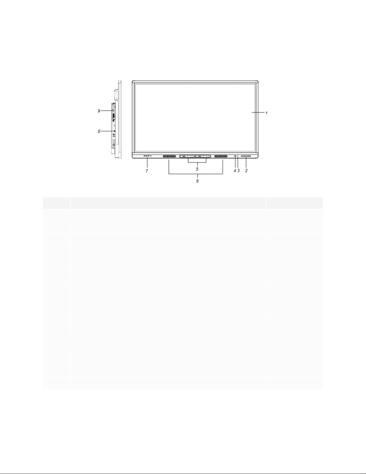
The display consists of the following components:
No. Name More information
Pictured
1 Screen Page14
2
3 Light sensor Page16
4 Remote control sensor / status light Page16
5
6
7 Front connector panel
8
9
Not pictured
10 AC switch Page44
11 Bottom connector panel Page38
Front control panel Page15
Pen (×2) Page15
Speakers Page16
Page15
Side connector panel Page37
iQ appliance (and Intel Compute Card) Page14
12 Remote control Page16
smarttech.com/kb/171257 13
Page 14
Chapter 1
Welcome
iQ appliance (and Intel Compute Card)
The iQ appliance is inserted in the accessory slot on the back of the following models:
l SBID-MX265
l SBID-MX275
l SBID-MX286
l SBID-MX365
l SBID-MX375
l SBID-MX386
Take advantage of iQ technology and access collaborative tools.
With the SBID-MX365, SBID-MX375, and SBID-MX386 models, you can insert an Intel Compute Card in the
appliance to provide a complete Windows 10 solution at your fingertips, without the need for an external
PC or cables.
CAUTION
The accessory slot’s maximum available power is 60 W. The slot is not a limited power source. To reduce
the risk of fire, make sure that accessories connecting to the slot satisfy the fire enclosure requirements
of IEC60950-1.
TIP
Use the Identify your iQ appliance model on the SMART support site to identify your model of iQ
appliance.
For more information about the iQ experience, see iQ experience on SMART’s support site.
Screen
The following are the dimensions for the display:
Model Diagonal Active touch area Active image area
SBID-MX365 64 1/2" (163.9cm) 573/8" × 32 3/4" (145.7cm ×
83.3cm)
SBID-MX375 74 1/2" (189.3 cm) 661/2" × 38" (168.8cm × 96.6cm) 65" × 36 1/2" (165 cm × 92.8cm)
SBID-MX386 85 5/8" (218.4 cm) 763/8" × 43 3/4" (194.1 cm ×
111.2cm)
56 1/4" × 31 5/8" (142.9 cm × 80.4
cm)
74 5/8" × 42" (189.5 cm × 106.6cm)
SBID-MX265 64 1/2" (163.9 cm) 573/8" × 32 3/4" (145.7cm ×
83.3cm)
smarttech.com/kb/171257 14
56 1/4" × 31 5/8" (142.9 cm × 80.4
cm)
Page 15
Chapter 1
Welcome
Model Diagonal Active touch area Active image area
SBID-MX275 74 1/2" (189.3cm) 661/2" × 38" (168.8 cm × 96.6cm) 65" × 36 1/2" (165 cm × 92.8cm)
SBID-MX286 855/8" (218.4 cm) 763/8" × 43 3/4" (194.1 cm ×
111.2cm)
74 5/8" × 42" (189.5 cm × 106.6cm)
Pens
The display comes with two pens.
The display’s bottom frame includes magnetic holders for the pens. Remove a pen from its holder and use
the pen to draw digital ink.
CAUTION
When you return a pen to the magnetic holder, make sure it’s centered in its holder to keep it from falling
and being damaged.
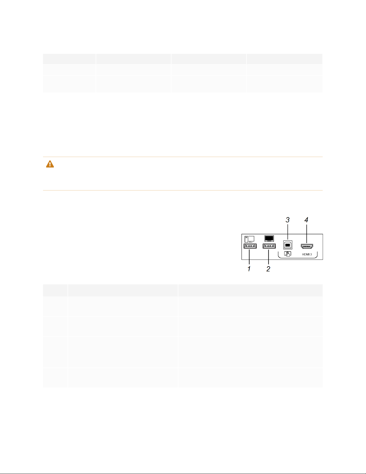
Front connector panel
The front connector panel includes connectors for USB peripherals and a
computer or other input source.
No. Name Procedure
1 USB 2.0 Type-A connector Connect USB drives and other devices that you want
to use with the currently selected input source.
2 USB 2.0 Type-A connector Connect a USBdrive to update the display’s
firmware.
3 USB 2.0 Type-B connector
Connect a USB cable to the display and computer to
provide touch control of the computer connected to
HDMI 3.
4 HDMI 3 input connector Connect a computer or other input source to the
display (see page33).
Front control panel
The front control panel contains the Power, Input Select, Menu, Freeze, Mute and volume control buttons.
smarttech.com/kb/171257 15
Page 16

Chapter 1
Welcome
Remote control
The remote control is an alternative to the front control panel for controlling the display.
Remote control sensor
The status light blinks green and red when it registers a button being pressed on the remote control.
Status light
The status light blinks green and red when it registers a button being pressed on the remote control.
When the status light is red, the display is in a low power state. To wake the display, press the Power button
on the front control panel or POWERon the remote control.
Ambient light sensor
The ambient light sensor can detect the room brightness and adjust the display’s brightness. Make sure
Auto is enabled in Brightness and volume in the display’s settings. See Brightness and volume on page77.
Internal speakers
The display includes two 10 W rms integrated speakers. You can also connect external speakers (see
Connecting external speakers on page35).
Accessories
Accessories for the display include the following:
l SBA-100 projection audio system
l SMART Audio 400 classroom amplification system
l USB extenders
l SMART PCM8 series OPS PC
SBA-100 projection audio system
The SBA-100 projection audio system consists of two 14 W speakers and is intended
for wall-mounted displays. You can control volume using the display’s front control
panel or the digital volume controls in a connected computer’s operating system.
For more information, see the SBA-100 projection audio system specifications
(smarttech.com/kb/171146).
smarttech.com/kb/171257 16
Page 17

Chapter 1
Welcome
SMART Audio 400 classroom amplification system
The SMART Audio 400 classroom amplification system provides high-quality audio
amplification. The system comes with a teacher microphone and optional student
microphone. Multiple speaker options are available, including wall- and ceiling-mounted
speakers. The amplifier receives audio signals from the microphones and translates
them into crystal-clear sound through the speakers.
For more information, see the SMART Audio 400 classroom amplification system specifications
(smarttech.com/kb/171137).
NOTE
The SMARTAudio 400 classroom amplification system is available only in Canada and U.S.
USB extenders
As noted in Connecting cables for room computers, guestlaptops and other input sources on page33, the
USB connection between the display and computer should be no longer than 16'(5m). If you need to
connect a computer that is more than 16' (5 m) from the display, use one of the following USB extenders:
Extender Specifications
USB-XT smarttech.com/kb/119318
CAT5-XT-1100 smarttech.com/kb/170202
SMARTrecommends only using USBextenders with the USB connectors on the side and bottom
connector panels on the display.
For more information, see:
l Troubleshooting and extending the USB 2.0 and USB 3.0 connection to your SMART interactive
display
l USBcables and connectors
SMARTPCM8 series OPS PC
The optional SMARTPCM8 series OPS PC (smarttech.com/kb/171429) provide a fully functional Windows
10 solution at your fingertips, without the need for an external PC or cabling.
More information
In addition to this guide, SMART provides the following documents for the display:
smarttech.com/kb/171257 17
Page 18

Chapter 1
Welcome
Document Link
User’s guide smarttech.com/kb/171284
SBID-MX165, MX175, MX186, MX265, MX275, MX286, MX365, MX375, and
smarttech.com/kb/171274
MX386 installation instructions
SBID-MX265 specifications smarttech.com/kb/171240
SBID-MX275 specifications smarttech.com/kb/171259
SBID-MX286 specifications smarttech.com/kb/171260
SBID-MX365 specifications smarttech.com/kb/171369
SBID-MX375 specifications smarttech.com/kb/171367
SBID-MX386 specifications smarttech.com/kb/171368
Comparison smarttech.com/kb/171161
These documents are available in the Support section of the SMART website (smarttech.com/support).
Scan the QR code on the cover of this guide to view the SMARTBoard MX series interactive displays
pages in the Support section.
smarttech.com/kb/171257 18
Page 19
Chapter 2
Moving the display to the installation site 19
Using transportation aides 20
Accommodating doorways, hallways and elevators 20
Dealing with cracked, chipped or shattered glass 21
Saving the original packaging 21
Installing the display on a wall 21
Choosing a location 22
Choosing a height 24
Assessing the wall 24
Selecting mounting hardware 25
Selecting a wall mount 25
Mounting the display 25
Installing the display on a stand 28
Using SMART mobile stands 28
Using a third-party stand 28
SMART recommends that only trained installers install the display.
This chapter is for installers. Installers should read this information along with the installation instructions
included with the display before they install the display.
WARNING
Improper installation of the display can result in injury and product damage.
Moving the display to the installation site
After your organization receives the display, you need to move it to the place where you plan to install it.
On occasion, you might also need to move the display to another location after initially installingit.
smarttech.com/kb/171257 19
Page 20

Chapter 2
Installing the display
IMPORTANT
l Move the display at your own risk. SMART cannot accept liability for damages or injury that occur
during the display’s transportation.
l When moving the display
o
Follow local safety regulations and standards.
o
Pack the display in its original packaging, including the pallet.
o
Move the display so that its top frame faces up.
o
Have at least two people move the display.
TIP
Display packaging may be labeled to indicate which side is the front. Look for “FRONT” on the packaging
to help orient the box during transportation.
Using transportation aides
You can use the following aides to move the display:
l Cart
l Furniture dolly
l Mechanical lift
Accommodating doorways, hallways and elevators
In some situations, you might need to remove the display from its packaging to move it through narrow
doorways or hallways or on to an elevator. In these situations, keep the foam pieces on the bottom corners
of the display. These foam pieces protect the display if you need to set it down during transportation.
You might also need to rotate the display so that its top frame faces to the side. You can do this during
transportation, but when you install the display, it must be in landscape orientation (with the top frame
facing up).
smarttech.com/kb/171257 20
Page 21

Chapter 2
Installing the display
Dealing with cracked, chipped or shattered glass
The display contains safety-tempered glass. Although this glass is heat-strengthened to help withstand
impacts, the glass can crack, chip or shatter if struck with enough force. (Safety glass is designed to break
into small pieces rather than sharp shards if it is broken.) Temperature changes can cause a minor crack or
chip to become worse, possibly causing the glass to shatter. See the knowledge base article, Shattered
glass on an interactive display, for information about conditions that can cause the display’s glass to shatter
even when it’s not in use.
If the display’s glass is cracked or chipped, have it professionally inspected and repaired at a SMART
authorized repair center. If the display’s glass shatters, carefully clean up the area and have the display
repaired or replaced.
CAUTION
For safety and to prevent further damage, do not continue to install or use the display if its glass is
cracked, chipped or shattered.
Saving the original packaging
Save the original packaging and repack the display with as much of it as possible if you ever need to move
the display after installation. This packaging was designed to provide the best possible protection against
shock and vibration.
CAUTION
Move the display only in the original packaging or replacement packaging purchased from your
authorized SMART reseller. Moving the display without correct packaging can lead to product damage
and voids the warranty.
NOTE
If the original packaging isn’t available, you can purchase the same packaging directly from your
authorized SMART reseller (smarttech.com/where).
Installing the display on a wall
Typically, you install the display on a wall in a classroom or meeting space.
smarttech.com/kb/171257 21
Page 22

Chapter 2
Installing the display
Choosing a location
Adisplay is typically installed at the room’s focal point, such as at the front of a classroom or meeting
space.
Selecting an appropriate location for the display is crucial for ensuring the best possible experience with
the product. Consider the following factors as you choose a location:
Factor Considerations
Room setup
Power and other
connections
The location allows users, including those in wheelchairs, access to the display.
l
Refer to local regulations regarding accessibility.
The location allows for multiple users to access the display at the same time.
l
The location accommodates room traffic patterns, and there are no tripping
l
hazards.
The display is not installed where it could be hit by a door or gate.
l
There are no nearby heat sources directed at the display such as a radiator or
l
heat vent.
There are no nearby shelving units, desks, or other furniture that has doors or
l
drawers that could hit the display.
Furniture, wall décor, and other room features, such as light switches and
l
thermostats, do not block the display and are not blocked by it. (You might be
able to move some of these room features to accommodate the display.)
The location is close to:
l
o
A power outlet
o
A network outlet (if you plan to use a wired network connection)
o
A room computer (if you plan to connect a room computer)
o
External audio systems and other devices that you want to connect to the
display
NOTES
o
If the location is not near a power outlet, consult an electrician for the
power setup you need.
o
Determine if you’ll need additional equipment, such as power bars,
additional cables, or cable extenders.
The location is not where the mains power supply enters the building.
l
smarttech.com/kb/171257 22
Page 23
Chapter 2
Installing the display
Factor Considerations
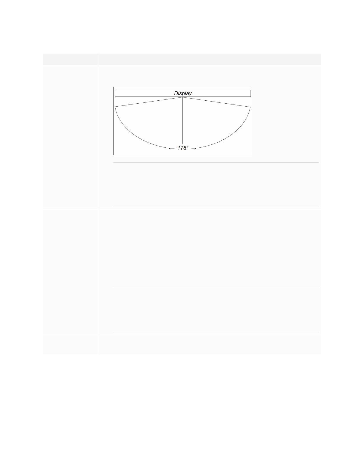
Visibility The display’s screen is clearly visible to all users in the room. SMART
recommends users sit within a 178° viewing area:
NOTE
The viewing area depends on the display’s resolution and a variety of other
factors. For more information, see the knowledge base article,
Recommended viewing distances and viewing angles for SMARTBoard
interactive flat panels.
Lighting The location is not near bright light sources, such as windows or strong
overhead lighting.
Risks of light Interference include:
o
Reduced visibility: Light sources can cause glare on the display’s screen,
reducing its visibility.
o
Touch system interference: Many displays use infrared (IR) light as a key
component of the touch system. Strong light that hits the display’s screen
directly can cause interference with the touch system and prevent the
display from working properly.
TIP
To reduce light interference, install blinds or shades on windows or skylights
and install switches to dim or turn off any lights shining directly on the
display’s screen. Keep in mind that sunlight can come through windows at
different angles at different times of the year.
Acoustics The room has good acoustics (see Configuring your SMARTBoard MX or
MX100 for the best audio performance).
smarttech.com/kb/171257 23
Page 24
Chapter 2
Installing the display
Factor Considerations
Environment and
ventilation
The location meets the environmental requirements in the display’s
l
specifications (see More information on page17).
The display isn’t subjected to strong vibrations or dust.
l
Ventilation systems don’t blow air directly on the display.
l
There is adequate ventilation or air conditioning around the display so that heat
l
can flow away from it and the mounting equipment. SMARTrecommends at
least 2" (5 cm) of space on all sides of the display for proper airflow.
If you plan to install the display in a recessed area, there is at least 4"(10cm) of
l
space between the display and the recessed walls to enable ventilation and
cooling.
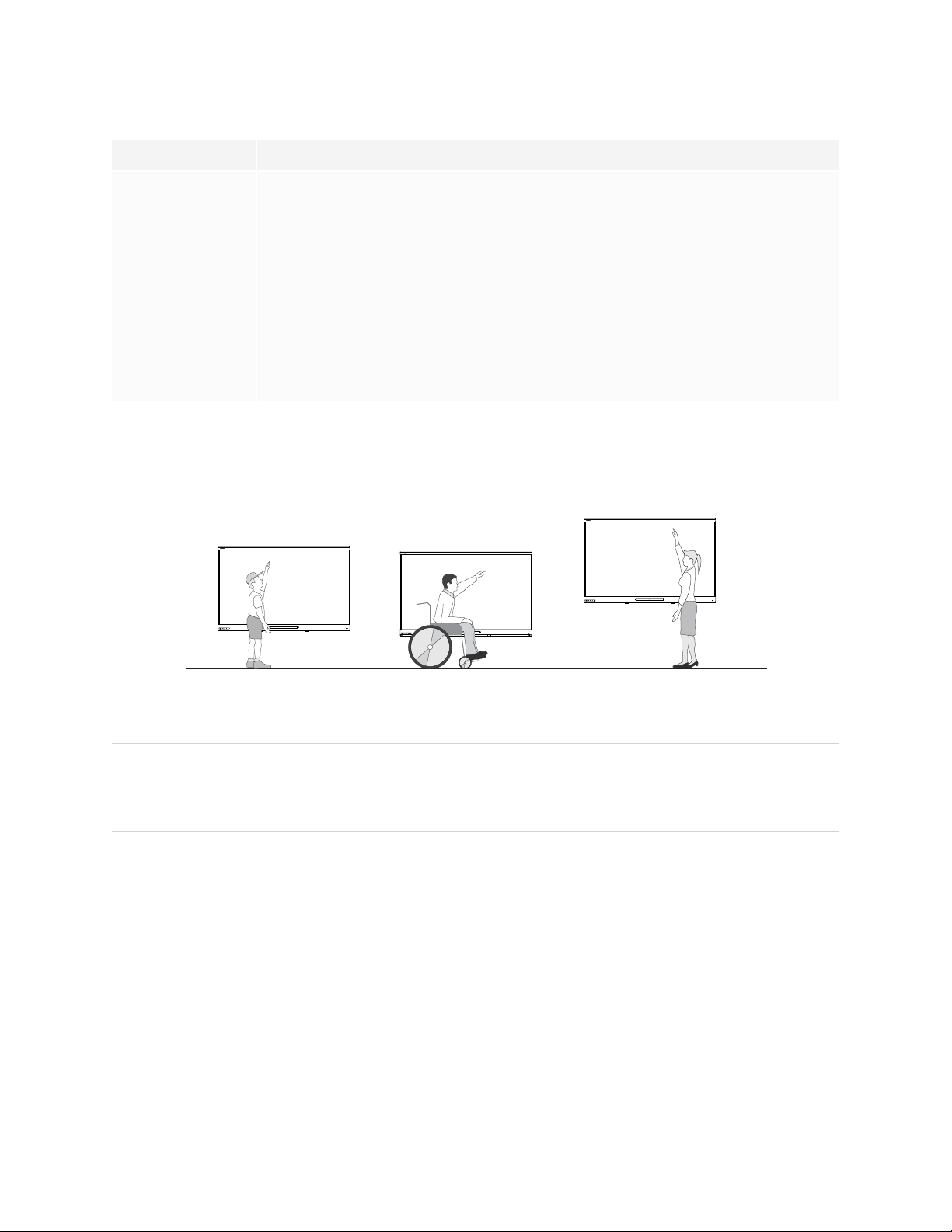
Choosing a height
Consider the general height of the user community when you choose the height for the display.
SMART recommends that you mount the display so that its top is 6'5" (1.9m) from the floor.
NOTE
If participants will be sitting at a steep angle (such as in a lecture hall), you may have to adjust the
installation height or angle.
Assessing the wall
Be sure the wall you’re installing the display on can support the weight of the display and mounting
equipment. If it can’t, consider using a SMART wall stand to transfer some of the weight from the wall to the
floor (see smarttech.com/accessories).
NOTE
Refer to the display’s specifications for its weight (see More information on page17).
smarttech.com/kb/171257 24
Page 25

Chapter 2
Installing the display
In some situations, you may need to request an engineering analysis to determine if the wall can support
the display.
Selecting mounting hardware
The mounting hardware required for installation varies according to the type of wall onto which the display
is being mounted.
Refer to Installation best practices for SMART products (smarttech.com/kb/171035) for the mounting
hardware required for the display.
Selecting a wall mount
It is always best to mount the display on a wall. If the wall can’t support the display’s weight, you can use
additional hardware to transfer some of the weight to the floor.
The display includes a pre-attached wall bracket which can be used to mount the display to the wall. See
the SBID-MX165, MX175, MX186, MX265, MX275 and MX286, MX365, MX375, MX386 installation
instructions (smarttech.com/kb/171274).
Contact your authorized SMART reseller (smarttech.com/where) for information on SMART’s mounting
options.
If you choose a third-party option rather than one of SMART’s mounting options, be sure the wall mount can
accommodate the display’s dimensions and support the display’s weight as well as the weight of any
attached accessories.
Mounting the display
Mount the display following the included installation instructions. In addition, consider the following:
The electrical and mechanical components of adisplay are designed to work properly when the display is
mounted in the orientation described in its installation instructions. Mounting the display in a different
orientation can cause malfunctions and will void the display’s warranty.
There are a number of potential hazards of mounting adisplay in a non-standard orientation or angle:
l Mounting adisplay horizontally (like a table top) can cause the glass to sag, damaging the display or
interfering with the display’s touch system.
l Non-standard orientation can affect ventilation, creating hotpots in equipment, premature failures and,
in displays that use projectors, exploding projector bulbs.
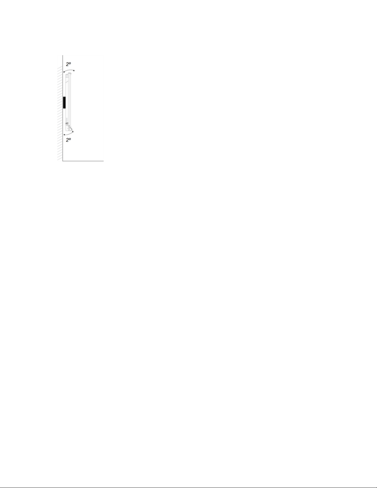
l Mount the display vertically (90° relative to the floor plus or minus 2° for tolerance) and in landscape
orientation. SMART doesn’t support mounting the display at other angles or in portrait orientation.
smarttech.com/kb/171257 25
Page 26
Chapter 2
Installing the display
l Use the included wall mount. Optionally, use a VESA-approved mounting plate that is rated for the
display’s weight and size.
smarttech.com/kb/171257 26
Page 27
Chapter 2
Installing the display
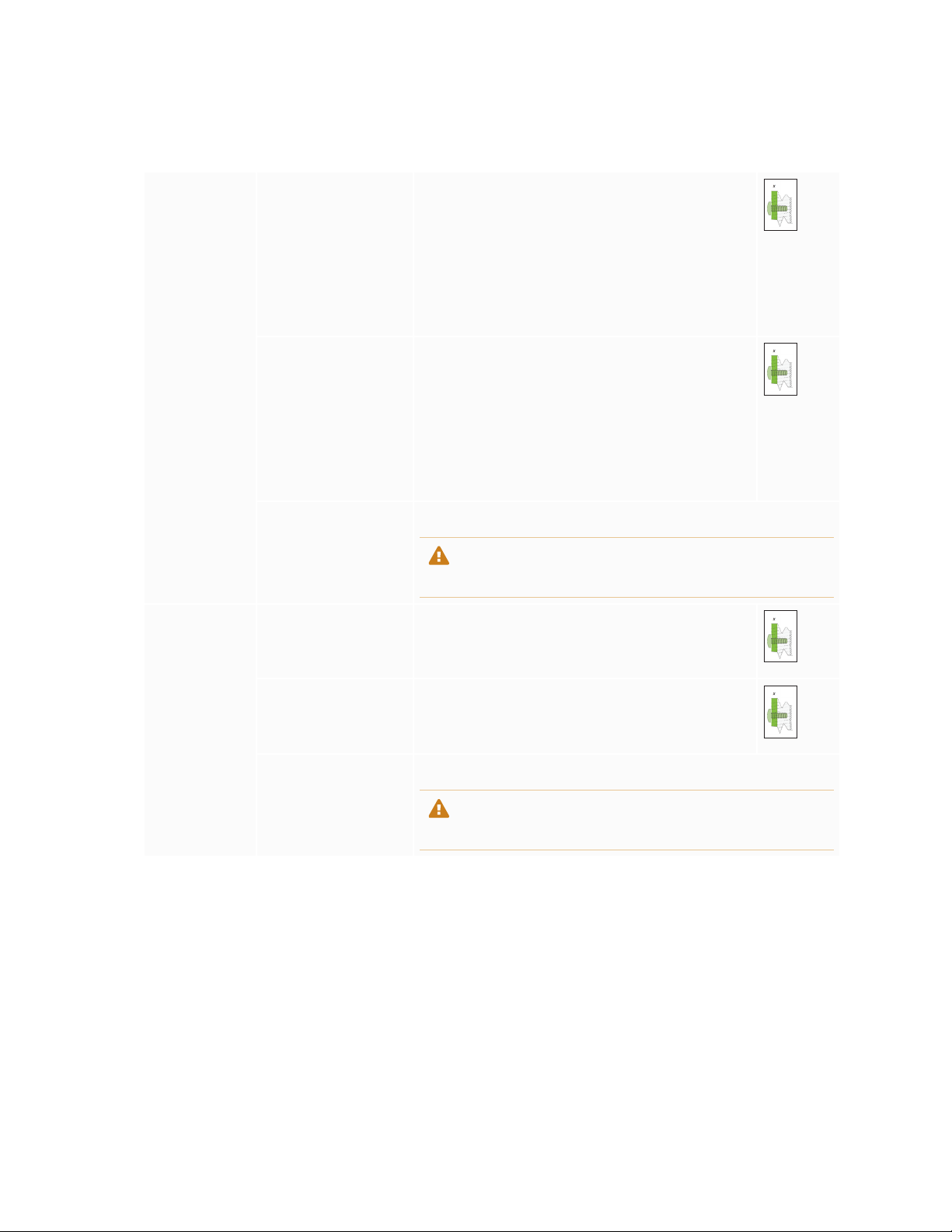
l If you’re not using the included bolts to fasten the wall mount to the display, see the following table.
SMARTBoard
MX365
SMARTBoard
MX265
SMARTBoard
MX375
SMARTBoard
MX275
Part number
1031028
Minimum M6 length
14 mm + x mm
where x is the combined thickness of the wall
mount and washer
Part number
1033445
Minimum M8 length
Part number
1031028
Maximum M6 length
18 mm + x mm
where x is the combined thickness of the wall
mount and washer
Part number
1033445
Maximum M8 length
Fasten force 97.36–177.01 in-lb. (11–20 N·m)
CAUTION
Do not over-tighten the bolts.
Minimum M8 length 18 mm + x mm
where x is the combined thickness of the wall
mount and washer
Maximum M8 bolt
length
30 mm + x mm
where x is the combined thickness of the wall
bracket and washer
Fasten force 97.36–177.01 in-lb. (11–20 N·m)
CAUTION
Do not over-tighten the bolts.
smarttech.com/kb/171257 27
Page 28

Chapter 2
Installing the display
SMARTBoard
MX386
SMARTBoard
MX286
Minimum M8 length 14 mm + x mm
where x is the combined thickness of the wall
mount and washer
Maximum M8 bolt
length
Fasten force 97.36–177.01 in-lb. (11–20 N·m)
30 mm + x mm
where x is the combined thickness of the wall
mount and washer
CAUTION
Do not over-tighten the bolts.
Installing the display on a stand
If you want to move the display from place to place or if it’s not possible to install the display on a wall, you
can install it on a stand.
Using SMART mobile stands
SMART mobile stands are designed for SMART interactive displays. They are height-adjustable. Some
models include integrated speakers, a locking cabinet to secure equipment, and casters that swivel and
lock for easy movement.
For more information about SMART mobile stands, see smarttech.com/accessories.
Using a third-party stand
For information on selecting and using a third-party stand, see Installing your SMARTBoard MX on a stand.
smarttech.com/kb/171257 28
Page 29

Chapter 3
Connecting the iQ appliance 30 Connecting power 30 Connecting to a network 31
AM50 iQ appliance 31
Connecting the Intel Compute Card 32
Connecting cables for room computers, guestlaptops and other input sources 33
Using recommended cables 33
Connecting to the side connector panel 34
Connecting to the bottom connector panel 34
Connecting to the front connector panel 35
Viewing a connected computer or other device’s input 35
Connecting external speakers 35
Connecting room control systems 36
Connector reference 37
Side connectorpanel 37
Bottom connectorpanel 38
Front connector panel 39
Other connectors 39
AM40 iQ appliance 40
AM50 iQ appliance 41
Connect the display to power after you install it but before you turn it on for the first time. You can also
connect cables for room computers, guest laptops or other input sources as well as for speakers and room
control systems.
By installing cables in advance, you make use of connectors that might not be accessible after the display
is wall-mounted. You can then run the cables across floors or behind walls as needed.
WARNING
Ensure that any cables that cross the floor to the display are properly bundled and marked to avoid a trip
hazard.
smarttech.com/kb/171257 29
Page 30

Chapter 3
Connecting power, cables and devices
Connecting the iQ appliance
For more information about installing the iQ appliance in SMARTBoard MX series interactive displays, see
the SBID-MX165, MX175, MX186, MX265, MX275, MX286, MX365, MX375, and MX386 installation
instructions (smarttech.com/kb/171274).
CAUTION
Install the AM50 iQ appliance and Intel Compute Card before you turn on the display for the first time.
IMPORTANT
If you’re installing an AM50 iQ appliance in a display, make sure the display’s firmware is updated to 1.8.7
or later. The display may not function properly if the display’s firmware is not updated. See Updating the
display’s firmware on page53.
Connecting power
SBID-MX265
SBID-MX365
Connect the supplied power cable from the AC power inlet on the side of the display to a power outlet.
NOTE
Refer to the display’s specifications for power requirements and power consumption information (see
More information on page17).
SBID-MX275
SBID-MX375
SBID-MX286
SBID-MX386
smarttech.com/kb/171257 30
Page 31

Chapter 3
Connecting power, cables and devices
Connecting to a network
IMPORTANT
Do not use the RJ45 jack on the AM40 iQ appliance to connect to a network.
The display requires a network connection for downloading software and
firmware updates, and a number of the iQ appliance’s apps require a network
connection as well. You can use one of the display’s RJ45 jacks (pictured) to
connect to a network, or you can use a Wi-Fi connection. For more information
about the display’s network connection and configuration, see Connecting to a
network.
You can also connect a computer to the display’s other RJ45 jack so the display and computer are
connected to the same network.
IMPORTANT
Do not use the RJ45 jack on the SMARTPCM8series OPSPC to connect to a network.
AM50 iQ appliance
There are three ways to connect the AM50 iQ appliance to a network:
l Wi-Fi
l connect an Ethernet cable from a network outlet directly to the AM50 iQ appliance’s RJ45 jack
smarttech.com/kb/171257 31
Page 32

Chapter 3
Connecting power, cables and devices
l connect an Ethernet cable from a network outlet to the display’s RJ45 IN jack, and then connect
another Ethernet cable from the display’s RJ45 OUT jack to the AM50 iQ appliance’s RJ45 jack
Connecting the Intel Compute Card
With the SBID-MX365, SBID-MX375, and SBID-MX386 models, you can insert an Intel Compute Card in the
slot on the AM50 iQ appliance to access the card’s Windows 10 operating system from the display.
IMPORTANT
Make sure the Intel Compute Card is inserted before you turn on the display.
NOTE
By default, the HDMI output extends the Windows desktop, and this can cause display problems in
certain configurations. If you experience issues, set the HDMI out to a mirrored desktop rather than the
default extended desktop. Right click, select Display settings, and set the secondary display to mirror the
first.
TIP
You can connect peripherals, such as a keyboard or mouse, to the Intel Compute Card using the USB
receptacles on the iQ appliance.
smarttech.com/kb/171257 32
Page 33

Chapter 3
Connecting power, cables and devices
Connecting cables for room computers, guestlaptops
and other input sources
You can connect cables to the display so that users can connect and use room computers, guest laptops or
other devices, such as Blu-ray™ disc players.
NOTE
If your display is configured with firmware 2.0.6 (and later), you can configure the HDMI version for each
HDMI connector as either HDMI 1.4 or HDMI 2.0. This allows you to connect HDMI 1.4 devices that are
incompatible with HDMI 2.0 connectors and would otherwise appear as DVI devices, see HDMI
[connector number]-EDID version on page78.
Using recommended cables
SMART recommends the following varieties of cable:
Cable type Maximum length Recommendation
HDMI 23' (7 m)
VGA 23' (7 m) Use VGA cables with all pins in their connectors fully
Stereo 3.5 mm 20' (6 m) [N/A]
USB 16' (5 m) Use a USB extender if the distance between the
Using cables that exceed these maximum lengths may produce unexpected results, such as degraded
picture quality or degraded USB connectivity.
1
Use only certified HDMI cables that have been tested to
support the performance standard you require.
populated and wired.
computer and the display is greater than 16' (5 m). For
more information, see USB extenders on page17.
1
The performance of cables longer than 23' (7 m) is highlydependent on the cable’squality.
smarttech.com/kb/171257 33
Page 34

Chapter 3
Connecting power, cables and devices
Connecting to the side connector panel
The side connector panel includes two HDMI video connectors: HDMI 1 and HDMI 2. Both connectors can
accommodate an HDMI cable for video and audio, and both support HDMI 2.0.
NOTES
l The USB Type-B connector for touch control is located on the bottom connector panel. See
Connecting to the bottom connector panel below.
l You can connect a wireless USB keyboard and mouse to the two USB Type-A connectors.
Connecting to the bottom connector panel
The bottom connector panel includes a video connector and USBconnector:
l VGA: This connector can accommodate a VGA cable for video.
l USBType-B: This connector can accommodate a USB cable for touch control for computers
connected to HDMI 1, HDMI 2 or VGA.
NOTE
When connecting a computer to the VGA connector, use the Stereo 3.5 mm in connector for audio.
smarttech.com/kb/171257 34
Page 35

Chapter 3
Connecting power, cables and devices
Connecting to the front connector panel
In addition to the three sets of video connectors on the side and bottom
connector panel, there is one set of computer connectors on the front
control panel:
l HDMI 3: This set of connectors can accommodate a USBcable for
touch control and an HDMI cable for video and audio. This input
supports HDMI1.4 with HDCP1.4.
l USBType-B: This connector can accommodate a USB cable for
touch control for computers connected to HDMI 3.
Viewing a connected computer or other device’s input
Users can tap the Input button to open the input selection menu. Tap an input source to view the computer
or other device’s input on the display.
For information about viewing a connecteds device’s input, see the SMARTBoard MX series interactive
display user’s guide (smarttech.com/kb/171284).
Connecting external speakers
The display includes two 10 W speakers, which are designed to provide sound at the front of a room. You
can connect external active speakers if you’re providing sound in a larger space. See SMART Audio 400
classroom amplification system on page17 for more information.
You can connect external speakers to the display using the stereo 3.5mm out
connector (pictured).
smarttech.com/kb/171257 35
Page 36

Chapter 3
Connecting power, cables and devices
The display also provides a Sony/Philips Digital Interface (S/PDIF) optical out
connector. S/PDIF is a digital audio transmission medium. You need an audio
receiver that supports S/PDIF to decode this connection to analog for use with
external speakers.
Connecting room control systems
A room control system enables users to control a room’s lighting, audio system and, possibly, the display.
Some installations may require you to integrate the display with a room control system.
You can use the display’s RS-232 connector to connect a third-party external control system to the display
(see Appendix C: Remotely managing the display on page80).
NOTE
Displays are not compatible with centralized remote control systems, such as a universal remote control.
smarttech.com/kb/171257 36
Page 37

Chapter 3
Connecting power, cables and devices
Connector reference
Side connectorpanel
The following diagram and table present the connectors on the display’s connector panel:
No. Connector Connects to Notes
1 HDMI 1.4 out (HDCP-
compliant)
2 USB 2.0 Type-A
connector
External monitor This connector is HDCP-encrypted
HDMI.
NOTE
HDMIout is an optional feature.
Contact your authorized SMART
reseller (smarttech.com/where)
for further ordering instructions.
USB drives and other devices Connect a USBdrive to update the
display’s firmware.
NOTE
If troubleshooting an issue with
the display, connect a USB
mouse to navigate the display’s
on-screen menu.
smarttech.com/kb/171257 37
Page 38

Chapter 3
Connecting power, cables and devices
No. Connector Connects to Notes
3 USB 2.0 Type-A
connector
USB drives and other devices Connect USB drives and other
devices that you want to use with
the currently selected input source.
4 HDMI 1 2.0 in HDMI 1 input (videoandaudio) See page33.
5 HDMI 2 2.0 in HDMI 2 input
See page33.
(videoandaudio)
6 RJ45 (×2) Network See page31.
Bottom connectorpanel
The following diagram and table present the connectors on the display’s bottom connector panel:
No. Connector Connects to Notes
1 USB 2.0 Type-B HDMI 1, HDMI 2 or VGA input
(touch)
See page33.
2 RS-232 Room control system See page80.
3 Stereo 3.5 mm out External speakers or audio
See page35.
system
4 S/PDIF out Optical digital audio output See page35.
5 Stereo 3.5 mm in VGA input (audio) See page33.
6 VGA in VGA input (video) See page33.
smarttech.com/kb/171257 38
Page 39

Chapter 3
Connecting power, cables and devices
Front connector panel
The following diagram and table present the connectors on the display’s convenience panel:
No. Name Procedure
1 USB 2.0 Type-A connector Connect USB drives and other devices that you want
to use with the currently selected input source.
2 USB 2.0 Type-A connector Connect a USBdrive to update the display’s
firmware.
3 USB 2.0 Type-B connector
4 HDMI 3 input connector Connect a computer or other input source to the
Connect a USB cable to the display and computer to
provide touch control of the computer connected to
HDMI 3.
display (see page33).
Other connectors
There are additional connectors on the bottom of the display (see Installing the display on a wall on
page21 and Appendix C: Remotely managing the display on page80).
smarttech.com/kb/171257 39
Page 40

Chapter 3
Connecting power, cables and devices
AM40 iQ appliance
This diagram and table describe the connectors on the AM40 iQ appliance:
AM40
No. Connector Connects to Notes
1 LED [N/A] LED lights green when the iQ
appliance is inserted in the
accessory slot and turned on.
2 Micro SD [N/A] This connector is a service port.
3 HDMI out [N/A] Do not use. See page37.
4 USB Type-A (×2) Supported peripherals [N/A]
5 RJ45 (AM40 iQ
appliance)
6 Eject button [N/A] This button ejects the Intel
[N/A] Do not use this connector. Use the
connectors on the display instead.
See page31.
Compute Card.
See Ejecting the Intel Compute
Card.
smarttech.com/kb/171257 40
Page 41

Chapter 3
Connecting power, cables and devices
AM50 iQ appliance
This diagram and table describe the connectors on the AM50 iQ appliance:
AM50
No. Connector Connects to Notes
1 Eject button [N/A] This button ejects the Intel
Compute Card.
See Ejecting the Intel Compute
Card.
2 Intel Compute Card [N/A] [N/A]
3
4 HDMI out [N/A] Do not use. See page37.
5 USB Type-A
6 USB Type-A
RJ45 Network Use this connector to connect the
AM50 iQ appliance to a network.
See AM50 iQ appliance on
page31.
Supported peripherals Supported USB devices connected
(CC)
Supported peripherals Supported USB devices connected
(iQ)
to this receptacle are available in
the Windows 10 operating system.
See Using Input.
connected to this receptacle are
available to the iQ experience.
See Chapter 3: Connecting power,
cables and devices on page29.
smarttech.com/kb/171257 41
Page 42

Chapter 3
Connecting power, cables and devices
No. Connector Connects to Notes
7 Power button and LED [N/A] LED lights when the appliance is
inserted in the accessory slot and
turned on.
Press the Power button to start
Windows 10 on the Intel Compute
Card.
8 Lock and Eject LEDs [N/A] The Lock LED lights when the
AM50 appliance shouldn’t be
removed from the display.
The Eject LED lights when it is safe
to remove the appliance from the
display. See Ejecting the Intel
Compute Card.
Not pictured
9
10
Intel Compute Card
label
iQ appliance (AM50)
label
[N/A]
[N/A]
The label for the Intel Compute
Card. The label is titled “Assembly,
PC, AM50”.
The label for the AM50 appliance.
The label is titled “Model / AM50”.
smarttech.com/kb/171257 42
Page 43

Chapter 4
You can connect the display to a network using Wi-Fi or an Ethernet connection. Before connecting the
display, your organization’s network administrators need to configure the network to allow users to update
the display’s firmware automatically and use all the features of the iQ experience.
To configure the network
1. To configure the network for use with all the iQ experience features, see Configuring the display’s
network connection in Configuring your organization’s network for a SMART display with the iQ
experience.
2. Open the port required for automatic firmware updates:
Protocol Port range
TCP 80
3. Add the following URLs to the network whitelist:
URL
http://api.lango-tech.cn
http://lango-tech.cn/
http://otaa.lango-tech.cn
http://otag.lango-tech.cn
http://downloads.smarttech.com
smarttech.com/kb/171257 43
Page 44

Chapter 5
CAUTION
l Install the AM50 iQ appliance and Intel Compute Card before you turn on the display for the first
time.
l After turning on and setting up the display, update the display’s firmware. See Updating firmware for
your SMARTBoard MX.
Turn on the display after mounting it and connecting power and devices.
To turn on and set up the display for the first time
1. Flick the switch beside the AC power inlet to the ON(I) position.
SBID-MX265
SBID-MX365
SBID-MX275
SBID-MX375
SBID-MX286
SBID-MX386
2. Select your preferred language, and then tap Next.
3. Select your country, and then tap Next.
4. Select your time zone, and then tap Next.
5. Set the date, and then tap Next.
6. Set the time, and then tap Next.
7. Name the display, and then tap Next.
smarttech.com/kb/171257 44
Page 45

Chapter 5
Turning on the display for the first time
8. If the display isn’t using a wired network connection, select a wireless network, and then tap Next.
IMPORTANT
The display needs an internet connection for downloading and installing important updates. Ask the
network administrator to confirm that the network has been correctly configured for the iQ
experience. For more information about network configuration, see Connecting a SMART display
with the iQ experience to a network.
9. Select the list of applications that will appear in the launcher, and then tap Next. For more information
about the apps, see the SMART Board MX series interactive displays user’s guide
(smarttech.com/kb/171284).
10. Select the apps you want to appear in the Apps Library, and then tap Next.
TIP
To change which apps appear in the Apps Library, see Launcher on page70.
11. Tap Finish.
The Welcome screen appears.
smarttech.com/kb/171257 45
Page 46

Chapter 6
Use SMART Settings on computers connected to the display to orient it.
If the display is connected to a computer and the pointer appears a distance from the actual contact when
you touch the screen, orient the display.
NOTE
You can use your finger or a pen to orient the display.
To orient the display when connected to a computer
1. Open SMARTSettings.
Operating system Procedure
Windows® 10
Windows 8
Windows 7 Select Start > All Programs > SMART Technologies >
macOS
2. Tap Orient.
3. Tap the red targets as they appear. Hold your finger or the tip of the pen at the center of each target,
and then lift the pen or finger. When you lift the pen or finger, the target moves to the next orientation
point.
IMPORTANT
Hold the pen at a right angle to the screen.
Select Start.
a.
Scroll to and select SMART Technologies > SMARTSettings.
b.
Open the Apps screen.
a.
Scroll to and select SMART Technologies > SMARTSettings.
b.
SMARTTools>SMARTSettings.
Press the SMARTBoard icon on the Mac menu bar.
a.
Press SMARTSettings.
b.
smarttech.com/kb/171257 46
Page 47

Chapter 6
Orienting the display
4. Continue until you’ve pressed all the targets.
The orientation window closes.
smarttech.com/kb/171257 47
Page 48

Chapter 7
Checking the display installation 48
Cleaning the screen 49
Cleaning the touch sensors 49
Maintaining ventilation 50
Preventing condensation 50
Replacing the pens 50
Turning the display off and back on 51
Resetting the display 51
Removing and transporting the display 51
Updating iQ system software 52
Applying an automatic iQ system software update manually 53
Updating system software manually 53
Updating the display’s firmware 53
Applying the display’s firmware update manually 54
Updating the display’s firmware manually 54
With proper maintenance, the display will provide years of use.
Checking the display installation
Inspect the display installation frequently to ensure that the display remains securely installed.
l Check the mounting location for signs of damage or weakness that can occur over time.
l Check for loose screws, gaps, distortions or other issues that could occur with the mounting hardware.
If you find an issue, contact a trained installer.
smarttech.com/kb/171257 48
Page 49

Chapter 7
Maintaining the display
Cleaning the screen
Follow these instructions to clean the screen without damaging its anti-glare coating or other product
components.
CAUTION
l Do not use permanent or dry-erase markers on the screen. If dry-erase markers are used on the
screen, remove the ink as soon as possible with a lint-free, non-abrasive cloth.
l Do not rub the screen with dense or rough material.
l Do not apply pressure to the screen.
l Do not use cleaning solutions or glass cleaners on the screen, because they can deteriorate or
discolor the screen.
To clean the screen
1. Turn off any connected computers.
2. Turn off the display (see Turning the display off and back on on page51).
3. Wipe the screen with a lint-free, non-abrasive cloth.
NOTE
You can also use a damp cloth with a drop of dish soap.
Cleaning the touch sensors
The display uses infrared (IR) transmitters and sensors around the display’s perimeter between the screen
and the frame. Dust buildup on the protective plastic can impair touch performance. Inspect these areas for
dust and clean them every week.
CAUTION
l Do not use compressed air to clean the sensors or borders.
l Do not use water or cleaning agents to clean the touch sensors.
l Do not apply too much pressure when cleaning the display because you can damage the plastic.
smarttech.com/kb/171257 49
Page 50

Chapter 7
Maintaining the display
To clean the IR transmitters and sensors
1. With a clean lint-free, non-abrasive cloth, gently wipe the plastic between the screen and the frame
around the perimeter of the display’s screen.
2. If dirt still remains, use 50% isopropyl alcohol (IPS) to clean the protective plastic between the screen
and the frame.
Maintaining ventilation
The display requires proper ventilation. Dust buildup in the ventilation holes compromises cooling and can
lead to product failure.
l Clean accessible ventilation holes monthly with a dry cloth.
l Use a vacuum cleaner with a narrow hose end fitting to clear the back ventilation holes regularly. You
might have to remove the display from the wall.
For more information on removing the display, see Removing and transporting the display on the next
page.
CAUTION
Avoid setting up or using the display in an area with excessive levels of dust, humidity, or smoke.
Preventing condensation
If the display has been moved from a cold environment to a warmer one (for example, from storage to the
installation site), let the display sit for a few hours to allow it to acclimate to the new temperature. Failing to
do so can cause humidity to build up in the space between the front glass and the LCD.
If condensation appears under the screen after you turn on the display, select an active video source and
leave the display on for 48 hours. If the condensation doesn’t dissipate, contact SMART Support if the
display is still under warranty.
If there is enough moisture between the layers to cause the moisture to drip and run, remove power
immediately and contact SMART Support if the display is still under warranty.
Replacing the pens
To prevent damage to the display’s anti-glare coating, replace a pen if its nib becomes worn. You can
purchase replacement pens from the Store for SMART Parts (seesmarttech.com/Support/PartsStore).
smarttech.com/kb/171257 50
Page 51

Chapter 7
Maintaining the display
Turning the display off and back on
In most situations, you can put the display to sleep when not using it following the instructions in the
SMARTBoard MX series interactive displays user’s guide (smarttech.com/kb/171284).
In some situations, such as when you need to transport the display or clean its screen, you need to turn the
display off for a period of time. You can turn it back on after.
To turn the display off
Press and hold the Power button on the front control panel for two seconds.
1.
To turn the display back on
Press the Power button on the front control panel.
Resetting the display
You can reset the display and the iQ appliance using the switch on the back of the panel.
To perform a factory reset, see Recovery on page79. A factory reset returns all options to their default
values.
To reset the display
1. Flick the switch to the OFF (O) position.
2. Flick the switch to the ON (|) position.
The display and iQ appliance reset.
Removing and transporting the display
If the display is wall mounted, you might need to remove it from its current location and transport it to
another location on occasion.
smarttech.com/kb/171257 51
Page 52

Chapter 7
Maintaining the display
To remove the display safely, use two or more trained installers.
WARNING
l Do not attempt to move the display by yourself. The display is very heavy.
l Do not move the display by connecting a rope or wire to the handles on the back. The display can
fall and cause injury and product damage.
IMPORTANT
Follow any documentation included with the third-party mounting hardware.
To remove the display
1. Turn off connected computers.
Turn off the display by pressing and holding the Power button on the front control panel for two
2.
seconds.
3. Flick the switch on the back of the display to the OFF(O) position.
4. Remove all accessible cables, connectors and antennae.
5. Remove the iQ appliance from the accessory slot.
6. Lift the display from its mounting location and insert it into its original shipping box.
WARNING
Do not place the display on a sloping or unstable cart, stand or table. The display could fall, resulting
in injury and severe product damage.
CAUTION
Do not leave the display face up, face down or upside down for an extended period. This could
cause permanent damage to the screen.
7. Remove the mounting brackets.
To transport the display
See Moving the display to the installation site on page19.
Updating iQ system software
When the iQ appliance is connected to the Internet, it updates its system software automatically.
smarttech.com/kb/171257 52
Page 53

Chapter 7
Maintaining the display
When a system software update is available, the iQ appliance downloads the update in the background
then waits for four hours of inactivity. When that happens, the display shows a two-minute countdown
before beginning the update. The countdown can be interrupted at any time. The update begins when the
countdown finishes. The display shows a blank screen for four minutes. When the update is complete, the
display shows the Home screen.
When the update is installing, touch, the front control panel and remote control will not respond.
NOTE
You can configure your organization’s network to allow or prevent automatic system software updates
(see Connecting to a network).
Applying an automatic iQ system software update manually
If the iQ appliance has downloaded the system software update but hasn’t yet applied the update, you can
start the update process manually from Settings.
To apply an automatic iQ system software update manually
From the Home screen, tap Settings .
1.
2. Scroll to Auto Update.
3. Under Check for Updates Now, tap Apply Update Now.
Updating system software manually
You can download system software updates at smarttech.com/downloads and update your display using a
USB drive.
Updating the display’s firmware
The display checks for firmware updates automatically, provided the display’s date and time are set
correctly (see Date & Time on page72) and the display is connected to the internet. The display notifies
you when a firmware update is available.
When a display is connected to the Internet and an update for the display’s firmware is available, the
display shows a message that an update is available.
l Tap Update to update the display’s firmware.
l Tap Ignore to skip that specific firmware update. The display won’t apply that update even if you
check for updates manually.
l Tap Cancel to update the display’s firmware at a later time.
smarttech.com/kb/171257 53
Page 54

Chapter 7
Maintaining the display
The display applies the firmware update automatically if no options are selected after a short time.
When the update is installing, touch, the front control panel and remote control will not respond.
To make sure the network is configured properly for firmware updates, see Chapter 4: Configuring the
network on page43.
Applying the display’s firmware update manually
To apply a system software update
1. A dialog box appears on the screen asking if you want to update the display’s firmware.
2. Tap Update to update the display’s firmware.
OR
Tap Cancel to update the display’s firmware at a later time.
To apply an automatic system software update manually
On the display, press the Menu button on the front control panel.
1.
2. Tap Update.
3. Under Update, tap Update.
Updating the display’s firmware manually
You can download display’s firmware updates at smarttech.com/downloads and update your display using
a USB drive.
1. Go to smarttech.com/downloads and download the update file for your size of display.
2. Copy the .zip file to a USB drive.
3. Insert the USB drive into the display USB.
Press Menu on the front control panel to open the display’s settings.
4.
5. Tap Update.
6. Tap Check.
A dialog box appears.
7. Tap USB.
smarttech.com/kb/171257 54
Page 55

Chapter 7
Maintaining the display
8. The upgrading software screen appears.
If the update includes an upgrade to the touch firmware, don’t touch the screen during an update.
9. Using the switch on the back of the display, turn off the display.
10. Wait 10 seconds.
11. Using the switch on the back of the display, turn on the display.
smarttech.com/kb/171257 55
Page 56

Chapter 8
Resolving remote control issues 57 Resolving general issues 57 Resolving issues with power 58 Resolving issues with image or video quality 58 Resolving issues with audio 61 Resolving issues with touch and digital ink 62 Resolving issues with remote management 64 Resolving issues with the iQ experience 64 Resolving issues with the Intel Compute Card 65 Resolving issues with software 65 Referring to the SMART knowledge base for additional troubleshooting information 66 Contacting your reseller for additional support 66
Finding the display’s serial number 66
Finding the iQ appliance serial number 66
Finding the Intel Compute Card serial number 67
The following information helps you resolve a variety of common issues with the display, including issues
with:
l Remote control
l Power
l Video
l Image quality
l Audio
l Touch and digital ink
l Remote management
l iQ experience
l Intel Compute Card
l Software
l SMART PCM8 series OPS PC
smarttech.com/kb/171257 56
Page 57

Chapter 8
Troubleshooting
Resolving remote control issues
Issue Solutions
Some buttons on the remote control
don’tdo anything.
The display doesn’t respond or
responds intermittently when you
press remote control buttons..
Not all buttons on the remote control have an effect on the display.See using-theremote-control.htm for a guide to the remote control’s buttons.
l Make sure you are using the correct remote control for your display. See using-the-
remote-control.htm for an image of the correct remote control.
l Make sure you are aiming the remote control’s IR transmitter at the remote control
sensor on the bottom right corner of the display while standing in front of the display,not
to the side.
l Make sure that both the remote control’s IR transmitter window and the display’s
remote control sensor are clean and unobstructed.
l Replace the remote control’s batteries.
Resolving general issues
Issue Solutions
You’ve forgotten the lock screen
password.
You forgot the Settings security
password.
The display can’t connect to a 5GHz
wireless network.
Contact SMARTSupport.
Contact SMARTSupport.
The wireless network may be operating on bands that the display doesn’t support.
Contact your network administrator.
The message “The board is not
compatiblewith the inserted iQ
appliance” appears on the screen.
The pen is broken. Contact SMARTSupport.
The Freeze button is not working. See The Freeze button is not working on SMART Board MX series interactivedisplays.
See "The board is not compatible with the inserted iQ appliance" message appears on
a SMART Board MX series interactive display.
smarttech.com/kb/171257 57
Page 58

Chapter 8
Troubleshooting
Resolving issues with power
Issue Solutions
The display doesn’t turn on and its
power light isn’t lit.
The display turns on but nothing
shows on the screen.
The display doesn’t turn on when you
use a connected computer’s mouse or
keyboard.
You’re experiencing other issues with
power, or the previous solutionsdon’t
resolve the issue.
l Make sure the power cable is securely fastened to the power outlet and the display.
NOTE
If the power cable is plugged into a power bar, make sure the power bar is securely
fastened to the power outlet and turned on.
l Make sure the switch on the back of the display is in the ON (I) position.
l Make sure the power outlet is workingby testingit with a different device.
l Make sure the power cable is working by testing it with a different device.
l Press the Power button to wake the display.
NOTE
The status light is red when the display is in a low power state.
l If the status light is solid green, see Resolvingissues with image or videoqualitybelow.
l Restart the display.
See Turning the display off and back on on page51.
l Make sure the computer is on.
l If the status light is red, press the display’s Power button to wake the display.
See Referring to the SMART knowledge base for additionaltroubleshootinginformation
on page66.
Resolving issues with image or video quality
Issue Solutions
You’re experiencing the followingor
similar issues with image quality:
l There are lines or snow on the
screen.
l The image is flickeringor
flashing.
smarttech.com/kb/171257 58
l Make sure the display’s firmware is updated to 1.8.7or later. The display may not work
properly if the display’s firmware is not updated. See Updating the display’s firmware on
page53.
Page 59

Chapter 8
Troubleshooting
Issue Solutions
You’re experiencing the followingor
similar issues with video:
l The videois distorted.
l There is visual noise.
l The image is dim.
There are bright spots on the screen.
NOTE
It is normal for some areas of the
screen to be slightlybrighter than
other, but these variations should
be minor.
l Make sure any connected computers are on and not in Standby mode.
l Set the connected computers’ resolution and refresh rate to values that the display
supports.
See Appendix E: Supported resolutions on page88.
l Restart the display and any connectedcomputers.
See Turning the display off and back on on page51.
l Make sure the cable is not longer than the maximum specified in the display’s
specifications.
l Make sure the cable is securely connectedto the videoconnectors on the displayand
the computer.
l If the video connection uses and extender or goes through a wall socket,try connecting
the display and computer directly.
l Replace the videocable to determine if the issue is with the cable.
l Make sure the iQ appliance is securely installed in the accessory slot and its power light
is on.
l Make sure your computer’s videodriver is up to date.
l Open the on-screen display menu. If it appears correctly,the issue is with the video
input.
l Take a photograph of the screen that shows the variation in brightness and send it to
SMART support. If SMART support determines that the issue is with the screen and the
display is under warranty, you may be eligiblefor a replacement.
l Make sure the cable is not longer than the maximum specified in the display’s
specifications.
l Make sure the cable is securely connectedto the videoconnectors on the displayand
the computer.
l If the video connection uses and extender or goes through a wall socket,try connecting
the display and computer directly.
Colors don’t appear correctly. l Minor differences in colors across displaysare common. This issue is not unique to
SMART products.
l If you’re using a VGA video input,use a different cable or connect a different source to
see if the issue is with the cable or input source.
l Make sure the cable is not longer than the maximum specified in the display’s
specifications.
l Make sure the cable is securely connectedto the videoconnectors on the displayand
the computer.
l If the video connection uses and extender or goes through a wall socket,try connecting
the display and computer directly.
l Perform a factory reset.
See Factory Reset on page72.
l Take a photograph of the screen that shows the issue with color and send itto SMART
support. If SMART support determines that the issue is with the screen and the display is
under warranty, you may be eligiblefor a replacement.
smarttech.com/kb/171257 59
Page 60

Chapter 8
Troubleshooting
Issue Solutions
The image is cut off or shifted to the
left or right.
The image doesn’t fill the entire
screen.
A persistent image appears on the
display.
The display is on, but nothing shows
on the screen.
l Adjust the connected computers’ video settings,particularly zoom, crop, underscan and
overscan.
See the computer’s operating system documentation.
l If the computer’s desktop is entirely black,change it to gray or a different color.
l If the computer’s desktop is extended across multiple screens, duplicate the desktop
across the screens or use the display as the only screen.
l Make sure the cable is not longer than the maximum specified in the display’s
specifications.
l Make sure the cable is securely connectedto the videoconnectors on the displayand
the computer.
l If the video connection uses and extender or goes through a wall socket,try connecting
the display and computer directly.
Adjust the connected computers’ video settings,particularly underscan or overscan.
See your computer’s operating system documentation.
See Image persistence or burn in on LCD displays.
l Make sure any connected computers are on and not in Standby mode.
l
Make sure the screen is working by pressing Input on the front control panel and
selecting the correct input source for your device.
l Restart the display and any connectedcomputers.
See Turning the display off and back on on page51.
l Replace the videocable connecting the computer to the display to determine if the issue
is with the cable.
l If the video source is HDCP-protected,make sure it’s connected to an HDMI port that
supports a compatible version of HDCP.The HDMI 3 port supports only HDCP1.4. Be
sure to connect devices that use HDCP 2.2 to the HDMI 1 or HDMI 2 port.
A computer is connectedto the
display, but only a “No Signal”
message appears on the screen.
If an AM50 iQ appliance with an Intel
Compute Card is installedin the
display and a “No Signal”message
appears on a blue screen.
l Connect the computer to one of the display’s video input connectors.
NOTE
In the input source menu, video input connectors that have a deviceconnected are
blue.
l Make sure the computer is the currently selectedinput.
l Make sure the connectedcomputer’s video connector is configured to output a
supported videosignal. See No video display output from a laptop.
l If you’re using two connectedvideo cables, use one longer cable or move the computer
so it’s withina single cable length of the display.Make sure the cable length is within the
maximum length specified in the display’s specifications.
l The computer is using a video resolutionor refresh rate that the display doesn’t
support. Set the computer to a supported resolution and refresh rate.
See Appendix E: Supported resolutions on page88.
l Make sure the computer hasn’t entered Sleepmode. Press a key on your computer’s
keyboard to wake it up.
Make sure the Windows operating system on the Intel Compute Card hasn’t entered
Sleepmode. Tap the display’s screen to wake up the operating system.
smarttech.com/kb/171257 60
Page 61

Chapter 8
Troubleshooting
Issue Solutions
No image appears on a deviceyou’ve
See Using a secondary display.
connectedto the display’s HDMI OUT
connector.
The image from a device connected to
the VGA port is cut-off or not centered.
You’re experiencing other issues with
videoor image quality,or the previous
l Make sure the computer’s background is not a dark or solid-blackimage.
l Switch to a different videoinput source, then switch back to the VGA input.
See Referring to the SMART knowledge base for additionaltroubleshootinginformation
on page66.
solutions don’t resolvethe issue.
Resolving issues with audio
Issue Solutions
You’re experiencing the followingor
similar issues with audio:
l No sound is coming from the
speakers.
l Sound is coming from the
speakers, but the volume is low.
l The sound is distorted or
muffled.
l Turn up the computer’s volume.
l If you’re using external speakers, make sure the speakers are turned on.
l Make sure the cables connecting the display to the computer are securely fastened.
NOTES
o
The display’s stereo 3.5 mm in connector works with the VGA input.
o
Connectingan audio cable to the display’s stereo 3.5 mm out connector
disables the internal speakers.
o
If you’re using the display’s S/PDIF out connector to connect a sound bar or
receiver for external speakers, See SMARTBoard MX series interactive
displays user’s guide (smarttech.com/kb/171257).
l Adjust the volume on the display and the connectedcomputer, and make sure both are
not muted.
l Make sure the display is set as the default audio device for the connected computer.
See the connected computer’s operating system documentation.
l If you’re using the display’s integrated speakers, set the volume for the computer and
any running applications to 80%, and then adjust the display’s volume.
OR
If you’re using external speakers, set the volume for the computer, any running
applications and the display to 80%, and then adjust the speakers’ volume.
l If you’re connectinga computer to the VGA connector, make sure an analog audio
cable is also connected from your computer’s audio output to the display’s analog audio
input.
smarttech.com/kb/171257 61
Page 62

Chapter 8
Troubleshooting
Issue Solutions
A whine or buzzing sound is coming
from the backof the display.
l Alldisplays emit some electrical noise.Such sounds may be more noticeablewith some
displays than with others. However, if you hear noise from the front of the display,
contact SMARTSupport.
l Make sure all devices are connected to the same power outlet or power bar.
l If the computer is connected to the display with analog audio cables (for example,3.5
mm audio cable with the VGA video input), make sure you are using high-quality cables
with electromagnetic interference (EMI) protection.Make sure audio cables don’t run
alongsidepower cables.
l Use a digital HDMI connection for videoand audio.Audio hum is far less common with
digital connections than it is with analog.
You’re experiencing other issues with
audio, or the previous solutions don’t
See Referring to the SMART knowledge base for additionaltroubleshootinginformation
on page66.
resolve the issue.
Resolving issues with touch and digital ink
Issue Solutions
You’re experiencing the followingor
similar issues with touch and digital ink:
l When users touch or write on
the screen, the pointer or digital
inkappears in the wrong place.
l Touch is not workingor is not
accurate.
l Touch control and digital ink are
intermittent.
l The display only responds to
touch on part of the screen.
l Digitalink disappears as you
write.
l If you’re using two pens, make sure they’re at least 2" (5 cm) apart.
l Make sure you are not holding the pen near its tip, and that the pen is at a right angle
(90°) to the screen.
l Restart the display.
See Turning the display off and back on on page51.
l If touch interactivity is slow, close some open applications on the computer.
l Make sure the pen nib is not worn. Replacement pens are available from the Store for
SMART Parts (see smarttech.com/Support/PartsStore).
l Make sure you are using a SMARTBoard MX series interactive display pen.
l Use a known working pen from another SMARTBoard MX series interactivedisplay to
checkif the issue is being caused by the pen.
l Clean the optical touch sensors. See Cleaning the touch sensors on page49.
l Make sure SMART Product Drivers and SMARTInk are installed and running on any
connectedcomputers, and orient your display.See Chapter 6: Orienting the displayon
page46.
l if touch is not accurate, make sure the computer’s image occupiesthe entire screen
area, with no black borders. If there are black borders, adjust the overscan or
underscan settings on your computer’s video settings,so that the image fillsthe screen.
l Open SMART Product Drivers and orient the display.This willset up a non-native touch
system orientation for your computer.
l Update the firmware.
l Confirm with the installers that the computer is connectedto the displaywith only a
singlecable.
l If touch interactivity is slow, close some open applications on the computer.
l if touch is not accurate, make sure the computer’s image occupiesthe entire screen
area, with no black borders. If there are black borders, adjust the overscan or
underscan settings on your computer’s video settings,so that the image fillsthe screen.
l Open SMART Product Drivers and orient the display.This willset up a non-native touch
system orientation for your computer.
smarttech.com/kb/171257 62
Page 63

Chapter 8
Troubleshooting
Issue Solutions
l Make sure the USB cable is securely fastened to both your computer and the display.
l Make sure the USB cable is not longer than the maximum specifiedin the display’s
l Use a USB 2.0 cable and make sure it’s connected to the correct USB connector that’s
l Make sure the latest version of SMART Product Drivers is installed on your computer.
l Remove any USB cable extenders. For best results, use a USB cable that’s no longer
l Remove any external infrared lightsources such as sunlight,incandescent or arc lights,
l Remove the display from the wall,calibrate it and confirm if this resolves the issue. If it
specifications.
associated with the video input source.
See Connecting cables for room computers, guestlaptops and other input sources on
page33.
SMARTBoard MX series interactive displays require SMARTProduct Drivers 12.10 or
later.
See smarttech.com/downloads.
than 16' (5 m).
desk lamps and infrared audio devices or move the display to another location in the
room.
does,check the wall and wall mount for issues.
The display responds to touch but not
to writing with a pen.
The display doesn’t respond to touch
at all.
You can’t write or draw in Microsoft®
Office.
You’re experiencing other issues with
touch and digital ink,or the previous
solutions don’t resolvethe issue.
l Make sure you are using a SMARTBoard MX series interactive display pen.
l Make sure the pen nib is not worn. A worn pen nib might be interpreted as a finger
touch.Replacement pens are available from the Store for SMART Parts (see
smarttech.com/Support/PartsStore).
l Reinstall or update SMART Product Drivers.
l A red X appearing on the SMART Product Drivers icon in your Windows task bar or Mac
menu bar indicates that no display is connected. If a red X appears, open SMART
Settings and use the connection wizard for assistance.
l Make sure any connected computers have detected the display’sUSB connection and
installeddrivers. On Windows computers, open Device Manager and make sure there is
no red X or yellow explanation mark (!) over the display’s icon. On Mac computers, open
System Information and ensur e there are no error messages in the display’s row.
l Make sure you’re using Microsoft Office 2013 or later.
l Reinstall or update SMART Product Drivers and SMARTInk.
l Refer to the SMART Ink user’s guide (smarttech.com/kb/171190) for more information
about inking in Microsoft applications.
See Referring to the SMART knowledge base for additionaltroubleshootinginformation
on page66.
smarttech.com/kb/171257 63
Page 64

Chapter 8
Troubleshooting
Resolving issues with remote management
Issue Solutions
You’re experiencing general issues
with remote management.
Usingthe command
setpowerstate=on doesn’t turn on
the display
l The display doesn’t respond to a
control command
l Commands are not followed by
a command prompt that
indicates the display is ready to
receive the next command.
l Make sure all the cable connectionsare secure.
l Be aware that some commands work only when the display is on.
See Configuring the serial interface settings on page81.
l Restart the display and the remote management system.
See Turning the display off and back on on page51.
l Configure the serial interface settings.
See Configuring the serial interface settings on page81.
l Add spaces around the operator symbol (=).
l
Ensure Power on RS232 is enabled in the display’s on-screen settingsmenu ( ).If the
display’s firmware is version 1.9.2 or earlier, disable Power saving mode in the display’s
on-screen settings menu. See Power saving mode on page78.
l The display is in a Power Saving mode in which the RS-232control system is not yet
operating.
Ensure the display is in a power state in which the RS-232 control system is ready to
receive commands. Ensure Power on RS232is enabled in the display’s on-screen
settings menu ( ).If the display’s firmware is version 1.9.2 or earlier,disable P ower
saving mode in the display’s on-screen settings menu.
l The display's firmware has not been updated to version 1.8.4or later. Check the
firmware version in the display'son-screen settings menu. See MX system version on
page79.
To update the display's firmware to version 1.8.4 or later, see Updating the display’s
firmware on page53.
l Commands might have been incorrectly terminated with a carriage return (0x0d) and a
linefeed (0x0a).
Terminate commands with only a carriage return (0x0d).
You’re experiencing other issues with
remote management, or the previous
See Referring to the SMART knowledge base for additionaltroubleshootinginformation
on page66.
solutions don’t resolvethe issue.
Resolving issues with the iQ experience
For information on resolving issues with the iQ experience, including the Whiteboard, SMARTNotebook
Player, Browser, Input and Screen Share apps, see Troubleshooting iQ system software.
smarttech.com/kb/171257 64
Page 65

Chapter 8
Troubleshooting
Resolving issues with the Intel Compute Card
Issue Solutions
An AM50 iQ appliance with
Intel Compute Card is
installed in the display but you
can’t select Intel Compute
Card from the Input Selection
Menu.
An AM50 iQ appliance with
Intel Compute Card is
installed in the display but you
can’t connect to a network.
Make sure the display’s firmware is updated to 1.8.7 or later. The
l
display may not work properly if the display’s firmware is not
updated. See Updating the display’s firmware on page53.
Make sure the Intel Compute Card is properly installed in AM50 iQ
l
appliance’s Compute Card port. Eject and reinsert the Intel Compute
Card. See Ejecting and inserting the Intel Compute Card.
The AM50 iQ appliance may have been installed after the display
l
was turned on for the first time. Restore the display’s factory
settings. See SMARTBoard MX series interactive displays
installation and maintenance guide (smarttech.com/kb/171257).
NOTE
Restoring factory settings resets all options to their default values.
Connecting the AM50 iQ appliance to a network:
o
wirelessly,
o
connect an Ethernet cable to the AM50 iQ appliance’s RJ45
jack from a network switch on the wall, or
o
connect an Ethernet cable to the AM50 iQ appliance and to the
display that is connected to a network with a wired or wireless
connection.
For information on resolving issues with the Intel Compute Card, including the drivers, see Troubleshooting
the iQ appliance (AM50) and Intel Compute Card.
Resolving issues with software
For information on resolving issues with SMART software, see the following pages in the Support section of
the SMART website:
l Troubleshooting SMART Notebook 18
l Troubleshooting SMART Learning Suite Online
l Troubleshooting SMART Ink 5
l Troubleshooting SMART Product Drivers 12
smarttech.com/kb/171257 65
Page 66

Chapter 8
Troubleshooting
Referring to the SMART knowledge base for
additional troubleshooting information
Refer to the SMART knowledge base for additional troubleshooting information:
community.smarttech.com/s/topic/0TO0P000000Xt5yWAC/mx-series
Contacting your reseller for additional support
If an issue you’re experiencing with the display persists or isn’t covered in this guide or the knowledge
base, contact your authorized SMART reseller (smarttech.com/where).
Your reseller might ask you for the serial number for the display or the iQ appliance.
Finding the display’s serial number
You can find the display’s serial number in the following ways:
l Look on the bottom frame
l Look on the back of the display
l In the display’s settings, under About.
NOTE
You can access the display’s settings using the Menu button on the front control panel.
Finding the iQ appliance serial number
You can find the iQ appliance’s serial number in the following ways:
l In the iQ settings (see Appendix A: Adjusting iQ settings on page68)
l Look on the iQ appliance
NOTE
You need to remove the iQ appliance from the display to locate the serial number.
smarttech.com/kb/171257 66
Page 67

Chapter 8
Troubleshooting
Finding the Intel Compute Card serial number
You can find the Intel Compute Card’s serial number in the following ways:
l Look on the label on the back of the Intel Compute Card. For information about ejecting the Intel
Compute Card from the iQ appliance, see Ejecting and inserting the Intel Compute Card.
NOTE
The serial number appears after S/N.
l From the Intel Compute Card's command prompt, execute the wmic bios get serialnumber
command.
smarttech.com/kb/171257 67
Page 68

Appendix A
Network settings 68
Personalization 69
Application settings 70
System settings 72
You can access settings using the icon on the Home screen.
NOTES
l Settings can apply to a user or to the entire system. User-level settings change depending on the
user who is signed in. System-level settings apply to all users. See the settings for more information.
l Some settings aren’t available while you’re signed in to your SMART account. Sign out of your
SMART account on the display to see all settings.
Network settings
Option Values Function Notes User or system
setting
Wi-Fi
Wi-Fi
[Wi-Finetwork name]
Wi-Fi MACaddress
Wi-Fi IPaddress
smarttech.com/kb/171257 68
On
Off
[N/A] Shows information about the
[N/A] Shows MACaddress for the network
[N/A] Shows IPaddress for the network the
Enables or disables Wi-Fi on the
display.
connectedwireless network.
the display is connected to.
display is connected to.
Turn on Wi-Fi to
discover
networks.
[N/A] System
[N/A] System
[N/A] System
System
Page 69

AppendixA
Adjusting iQ settings
Option Values Function Notes User or system
setting
SMARTiQ Ethernet
Advanced options
StaticIP (Use DHCP)
Proxy (Use proxy)
Proxy (Auto-configure)
MAC address
StaticIP
Proxy
Bluetooth
SMARTCloud
SMART Cloud Status
[N/A] Options available when an Ethernet
[N/A] System
cable is connected
On
Off
On
Off
On
Off
Enables or disables DHCP to assign
the display an IP address.
Enables or disables a proxy server for
connecting to the network.
Enables or disables automatic
configuration of the proxy server for
[N/A] User
[N/A] User
[N/A] User
connecting to the network.
[N/A] Shows information about the network
[N/A] System
the display is connected to.
[N/A] Shows information about the network
[N/A] System
the display is connected to.
[N/A] Shows information about the network
[N/A] System
the display is connected to.
[N/A] Shows information about the display’s
Bluetooth.
Turn on Bluetooth
to view available
System
Bluetooth
devices.
[Status] Shows the status of SMART Cloud. [N/A] System
ServiceRegion
[N/A] Shows the service region. [N/A] System
Personalization
Option Values Function Notes User or system
setting
Wallpaper
[Wallpapers] Selectthe wallpaper that
appears in the
background.
l 1920 × 1080 images
work best
l The display supports
.png and .jpg file
formats
l See Changing the
display’s wallpaper.
User
smarttech.com/kb/171257 69
Page 70

AppendixA
Adjusting iQ settings
Application settings
Option Values Function Notes User or system
setting
Launcher
SMARTNotebookPlayer
Browser
Screen Share
SMARTWhiteboard
Whiteboard Storage
Library
Save Whiteboards in
Library
MobileApp
Saving Whiteboards
On
Off
On
Off
On
Off
[N/A] [N/A] [N/A] User
On
Off
For 1 week
For 1 Month
Indefinitely
On
Off
Enables or disables SMART
Notebook Player in the Apps Library.
Enables or disables Browser in the
Apps Library.
Enables or disables Screen Share in
the Apps Library.
Enables or disables saving kapp
Whiteboard sessions.
Sets how long kapp Whiteboard
sessions are saved.
Enables or disables the Capture
function in the SMARTkapp app.
[N/A] User
[N/A] User
[N/A] User
[N/A] User
[N/A] User
If this optionis off, the
QRcode is not visible.
The SMARTkapp
app cannot connect
to the display and
your mobile device
cannot save
snapshots of the
display in the app.
User
Sharing Whiteboards
Annotation
Enable annotation layers
Screen Share
Require Permission
smarttech.com/kb/171257 70
On
Off
On
Off
On
Off
Enables or disables the Invite
function on the SMARTkapp app.
Enables or disables annotations on
the Browser and Screen Share
apps.
Enables or disables automatic
connection from a devicesharing its
screen.
If this optionis off,
you cannot invite
peopleto your
session.
[N/A] User
[N/A] System
User
Page 71

AppendixA
Adjusting iQ settings
Option Values Function Notes User or system
setting
AirPlay
Google Cast
Miracast
Performance Logging
Miracast Connection
Handling
On
Off
On
Off
On
Off
On
Off
On
Off
Enables or disables the AirPlay
protocol.
Enables or disables the Google Cast
protocol.
Enables or disables the Miracast
protocol.
SMART Support may ask users to
enable Performance Logging to
help diagnose issues.
When enabled,the display
disconnects from the network when
a deviceshares its screen using
Miracast.
AirPlay is enabled by
default.
Google Cast is
enabled by default.
Miracast is enabled
by default.
IMPORTANT
Devices that use
AirPlay and
Google Cast can’t
connect to the
display while a
Miracast device is
connected.
Performance
Logging is disabled
by default.
SMARTrecommends
enabling this setting
for areas with high
network saturation
or busy networks.
System
System
System
System
System
Reset Screen Share
[N/A] Closesand restarts the Screen
Share app and its discovery
services.
IMPORTANT
Onlyone device
can connect to the
display when
Miracast is
enabled.
You can restart
Screen Share as a
troubleshootingstep
if a mobile device or
computer can’t find
or connect to the
display.
System
smarttech.com/kb/171257 71
Page 72

AppendixA
Adjusting iQ settings
System settings
Option Values Function Notes User or system
setting
Date & Time
Automatic Date & Time
Date
Time
24 Hour Time
Time Zone
Language
On
Off
[N/A] Sets the display’s date. Disable
[N/A] Sets the display’s time. Disable
On
Off
[N/A] Sets the display’s time zone. [N/A] System
[Languages] Sets the language for the settings
Sets the display’s date and time
automatically.
Shows the display’s time using the 24hour clock.
menu.
Configure the
network to allow
Network Time
Protocol(NTP)
requests to
internet time
servers. See
Connectingto a
network.
Automatic date
& time to set the
date manually.
Automatic date
& time to set the
time manually.
[N/A] User
To selecta
different
language for the
on-screen display
menu, see [XREF].
System
System
System
User
Country
Diagnostics
Factory Reset
Save LogFile
Improve the Experience
Support ID
smarttech.com/kb/171257 72
[Countries] Sets the display’s country. [N/A] System
[N/A] Resets alloptions to their default
values.
[N/A] Copy diagnostic logs to a USB drive. [N/A] [N/A]
On
Off
[Support ID] Shows the support ID associated with
Sends usage statisticsand error
reports to SMART.
the display.
Only
administrators
should reset the
display.
[N/A] User
[N/A] [N/A]
[N/A]
Page 73

AppendixA
Adjusting iQ settings
Option Values Function Notes User or system
setting
Security
LockDown Settings
Install certificates
Clean up
Clean UpPolicy
Clean Upthe whiteboard
Clean Upthe browser
Clean Upother
applications
[N/A] Lockdown the display’s settings using
a certificate on a USB drive.
See Lockingdown
the Settings app
System
for more
information.
[N/A] Installcertificates to connect to a
[N/A] System
network.
Disabled
Sets how often the display cleans up. [N/A] User
Manually reset
with the Clean Up
button in the
launcher
1 hour
2 hours
3 hours
1 day
[N/A] Saves the Whiteboard session to the
[N/A] User
Library and erases the Whiteboard.
[N/A] Closes the browser tabs and clears
[N/A] User
the history,cache, and cookies.
[N/A] Closes open applications. [N/A] User
Software Update
Updates Channel
Stable Channel
Beta Channel
Sets which iQ system software
updates the displayreceives.
When switching
from the Beta
channel to the
Stable channel,a
factory reset
occurs. See
page72 for more
information about
factory reset.
For more
information about
the Beta Channel,
see Switching to
the Beta channel.
System
smarttech.com/kb/171257 73
Page 74

AppendixA
Adjusting iQ settings
Option Values Function Notes User or system
setting
Checkfor Updates Now
Remote Management
Launch Remote
Management Settings
Remote Management
Enabled
RadixViso version
About
Board Name
Help
[N/A] Checksfor updates to the system
software.
If an update is
available,the text
[N/A]
changes to Apply
NOTE
update now.
The display must be connected to
the internet to check for system
software updates or a USB drive
with the system software update
fileis connectedto the display.
[N/A] Configure the display’s connection
settings with the Radix Viso server.
This option is only
enabled when
System
Remote
Management is
enabled.
On
Off
Enables or disables Remote
Management on the display.
[N/A] User
[N/A] Shows the RadixViso version. [N/A] System
[N/A] Select a name for your display. [N/A] System
[N/A] Shows the SMART support site. [N/A] [N/A]
Send Feedback
Board Details
Build Number
Serial Number
Firmware Details
Touch controller version
Scaler version
Legal Information
End User License
Agreement
Open Source Licenses
SMARTIntellectual
Property
[N/A] Send feature request to SMART. [N/A] [N/A]
[N/A] [N/A] [N/A] [N/A]
[N/A] Shows the iQ system software’s
[N/A] [N/A]
version number.
[N/A] Shows the iQ appliance serial number [N/A] [N/A]
[N/A] [N/A] [N/A] [N/A]
[N/A] Shows the display’s touch controller
[N/A] [N/A]
version.
[N/A] Shows the display’s scaler version. [N/A] [N/A]
[N/A] [N/A] [N/A] [N/A]
[N/A] Shows the SMART end user license
[N/A] [N/A]
agreement.
[N/A] Shows the open source licenses. [N/A] [N/A]
[N/A] Shows the SMART intellectual
[N/A] [N/A]
property information.
smarttech.com/kb/171257 74
Page 75

Appendix B
Exiting the display’s settings 75
Network 75
Screen lock 76
Advanced 77
Update 78
Recovery 79
About 79
You can access the display’s settings using the Menu button on the front control panel.
Exiting the display’s settings
To exit the display’s settings
Tap Exit
OR
press the Menu button on the front control panel
Network
Option Values Function Notes
Ethernet
Ethernet
Get IP address
automatically
Enable
Disable
Enable
Disable
Enables or disables connecting to a
network with the wired RJ45jacks
The display automatically acquires an
IPaddress from a DHCPserver on
your network
Enabling Ethernet disables Wi-Fi.
Enabling Wi-Fihotspot allows you to
connect your mobiledeviceto the
display using Wi-Fi for screen sharing.
smarttech.com/kb/171257 75
Page 76

AppendixB
Adjusting display settings
Option Values Function Notes
StaticIPaddress
Wi-Fi
Wi-Fi hotspot
Wi-Fi hotspot
Set up Wi-Fi hotspot
Network status
Enable
Disable
Enable
Disable
Enable
Disable
[N/A] Sets the network name, security,
[N/A] Shows information about the display’s
Enter a staticIPaddress Use the on-screen keyboard or
connect a USB keyboard to the Display
USB Type-A connector on the front
connector panel to enter information.
Enables or disables connecting to a
network wirelessly
Enables or disables the Wi-Fi hotspot The lockscreen appears after the
password and access point frequency
current network connection
Turn on Wi-Fi to discover networks.
Enabling Wi-Fidisables Ethernet.
display wakes up from sleep.
Use the on-screen keyboard or
connect a USB keyboard to the Display
USB Type-A connector on the front
connector panel to enter information.
[N/A]
Screen lock
Option Values Function Notes
Lock screen mode
Lockscreen mode
Image
Disable
Lockscreen password
Settings security
Enable
Disable
[N/A] Selecta custom image for the lock
[N/A] Turns off the custom image for the
Enable
Disable
Enable
Disable
Turns lock screen on or off [N/A]
screen
lockscreen
Set a PINto unlockthe lock screen [N/A]
Set a PIN to access certain settings When Settings security is enabled, only
l Supports .png,.jpg, .bmp files
l Save the wallpaper file to a
USBdrive and insert it into the
USB port. See Front connector
panel on page15.
[N/A]
Advanced and About settingsare
available.To access the other settings,
tap the setting and enter the PIN.
smarttech.com/kb/171257 76
Page 77

AppendixB
Adjusting display settings
Advanced
Option Values Function Notes
Display
Walllpaper
Launcher
Home screen
HDMI out
Sleep
Brightness and volume
Auto
[N/A] Sets the background image on the
display
[Apps] Selectwhich apps appear in the
launcher.
[Apps] Selectthree apps to appear on the
home screen
480p
1080p
4K
15 minutes
30 minutes
45 minutes
60 minutes
Always on
[N/A] Automaticallysets the display’s
Select the output resolution Ensure the device that is receiving the
When a time interval is selected,the
display’s screen willturn off even if the
connectedcomputer or deviceis still
on.
brightness based on the room’s
brightness.
l Only.png, .jpg,.bmp files are
supported
l Save the wallpaper file to a
USBdrive and insert it into the
USB port. See Front connector
panel on page15.
[N/A]
Tap the app you want to remove from
the home screen. Then select the app
you want to appear on the home
screen instead.
display’s HDMI out signal matches the
selectedoutput resolution.
If the iQ experience is selected,the
display’s screen willnot turn off when a
time interval is selected.
The ambient lightsensor can detect
the room brightness and adjust the
display’s screen brightness
Manual
Volume
OTA
OTAserver
Automaticallycheckfor
updates
smarttech.com/kb/171257 77
[N/A] Sets the display’s brightness level Disable Auto to set the brightness
manually
[N/A] Sets the display’s volume level [N/A]
[OTA servers] Sets which server the display connects
to for updates
NOTE
The display must be connected to
the Internet to check for system
software updates.
Enable
Disable
Enables or disables checking and
downloading updates for the display’s
firmware
Default is Auto.
Enabled by default.
If this is disabled, manuallycheckfor
updates in Update on the next page.
Page 78

AppendixB
Adjusting display settings
Option Values Function Notes
Power saving mode
Default input
Use default touch settings
Power on RS232
HDMI [connector number]-
EDID version
Enable
Disable
OPS
HDMI1
HDMI2
HDMI3
VGA
Enabled
Disabled
Enabled
Disabled
Default
EDID 1.4
EDID 2.0
Enables or disables power saving
mode
Select a default input when the display
is turned on.
Sets the number of touch points. Defaultis Enabled.
When enabled,RS-232 can be used to
turn on the display from low power
state (soft off).
Sets the HDMI-EDID version of the
display's activeHDMI connector to
Default,EDID 1.4 or EDID 2.0.
NOTE
Default is selectedby default.
Enabled by default.
When enabled,power saving mode
activates after 90 minutes of inactivity.
Enabling Power saving mode makes
RS-232 control of the display
unavailable untilthe displayis turned
on using the power button on the front
control panel .
OPSis enabled by default.
Select Enabled to use 10 touch points.
Select Disabled to use 20 touch points.
Default is Disabled.
When Defaultis selected, the display
automatically detects a connected
device’s HDMI-EDID version and
switches the display's HDMI connector
between EDID 1.4 and 2.0. This feature
might not work consistently for older or
non-compliant EDID 1.4 devices.
Update
Option Values Function Notes
Firmware version
Update
smarttech.com/kb/171257 78
[N/A] Shows technicalinformation about the
display’s scalar firmware.
[N/A] Checksfor updates to the system
software
To see the firmware version use the
About option (see About on the next
page.
If an update is available,the text
changes to Applyupdate now.
NOTE
The display must be connected to
the Internet to check for system
software updates. Check the
display’s network settings.
To checkthe network settings,see
Network on page75.
Page 79

AppendixB
Adjusting display settings
Recovery
Option Values Function Notes
Restore user settings
Restore factory settings
[N/A] Resets any optionsthe user may have
changed
[N/A] Resets alloptions to their default
values
[N/A]
Onlyadministrators should reset the
display.
About
Option Values Function Notes
Name
RAM
Localstorage
Resolution
Android
[N/A] Selecta name for your display This name is different from the display
name set in the iQ system software.
[N/A] Shows how much RAMis installed in
the display
[N/A] Shows how much storage memory is
available and how much is currently in
use
[N/A] Shows the display’s current screen
resolution
[N/A] Shows the current version of the
Android operating system on the
display
[N/A]
[N/A]
[N/A]
[N/A]
MX system version
Touch kit
HDMI-out
MAC address
Serial number
License
User agreement
[N/A] Shows the current version of the
display’s scalar firmware
[N/A] Shows the current version of the touch
system firmware
[N/A] Shows the current version of the
HDMI-out system firmware
[N/A] Shows the network’s MACaddress [N/A]
[N/A] Shows the display’s serial number [N/A]
[N/A] Shows third-party component licenses [N/A]
[N/A] Shows the SMARTEULA [N/A]
[N/A]
[N/A]
[N/A]
smarttech.com/kb/171257 79
Page 80

Appendix C
Configuring the serial interface settings 81 Communication structure 81 Power states 84 Commands 85
You can connect a control system or terminal emulation program on your computer to the display's room
control input and remotely select video inputs, change power and sleep states, and get information about
the display’s current settings, such as current input source, contrast and power state.
Connect an RS-232 cable from the control system or the computer’s serial port to the RS-232connector on
the bottom of the display.
IMPORTANT
Use only a standard RS-232 cable. Do not use a null modem cable. Null modem cables typically have
ends of the same type.
smarttech.com/kb/171257 80
Page 81

AppendixC
Remotely managing the display
Configuring the serial interface settings
Configure the control system or computer’s serial interface before sending commands to the display.
To configure the serial interface settings
1. Turn on the display.
2. Turn on the control system or computer, and access the serial data communications settings.
3. If using a terminal emulation program on a computer, activate local echo.
4. Configure the serial interface settings using the following values, and then press ENTER.
Baud rate 19200
Data length 8
Parity bit None
Stop bit 1
When a command prompt (>) is received by your control system or terminal emulation program, the
display can accept commands. If the command prompt isn’t received, send a carriage return character
(0x0d) to the display (press ENTER on your keyboard if you’re using a terminal emulation program on
your computer).
NOTE
If no message or an error message is received in the control system or terminal emulation program,
the serial interface isn’t configured correctly. Repeat steps 3 and 4.
Communication structure
Communication consist of a command argument, property affected, operator symbol, a value to apply, and
a terminating carriage return character (0x0d).
IMPORTANT
When manually entering commands into a terminal emulation program, commands must be terminated
with only a carriage return character (0x0d). If you terminate a command with both a carriage return
character (0x0d) and a line feed (0x0a), the command may not be processed and the command prompt
that indicates readiness to receive the next command may not be received.
smarttech.com/kb/171257 81
Page 82

AppendixC
Remotely managing the display
NOTES
l The display won’t respond to RS-232 commands when it is in a low power state (soft off). Disable
Power saving mode to prevent the display from entering a low power state. See Power saving
mode on page78.
l When you first turn on the display, the RS-232 connector operates in a special diagnostics mode
instead of control mode, and the display won’t respond to control commands. In addition, the
connected control system or terminal emulation program might receive unexpected data
characters.
Program a connected control system to ignore the unexpected data characters and only send
commands after it receives the command prompt (>).
If you haven’t disabled Power saving mode, you’ll see the unexpected characters every time you
turn on the display.
CORRECT
>set input=HDMI1
INCORRECT
>set HDMI1
To use the room control system to get information about the display or to adjust display settings, send
commands after receiving a command prompt (>), and then wait for the display’s response before sending
another command.
CORRECT
>get volume
volume=55
>
If you send a command that the room control system doesn’t recognize, you receive an invalid command
response.
The example contains an extra space in the volume command.
INCORRECT
>set vol ume=65
invalid cmd=set vol ume=65
>
smarttech.com/kb/171257 82
Page 83

AppendixC
Remotely managing the display
NOTES
l Use ASCII formatted commands.
l Commands aren’t case-sensitive.
l When manually entering commands into a terminal emulation program, review each entry carefully
before you press ENTER to send a carriage return (0x0d) to terminate the command.
l Don’t send another command until you receive the response and the next command prompt.
To identify the current value of a setting
Use a get command.
This example shows how to get the display’s current volume setting:
>get volume
volume=55
>
To assign a value to a setting
Use a set command.
This example sets the volume to 65:
>set volume=65
volume=65
>
smarttech.com/kb/171257 83
Page 84

AppendixC
Remotely managing the display
To increase or decrease the value of a setting
Use the set command to increase or decrease the value by a designated number.
This example increases the volume by 5:
>set volume+5
volume=70
>
This example decreases the volume by 15:
>set volume-15
volume=55
>
Power states
The display has the following power states:
Power state Description
ON The display is in normal operating mode.
READY The screen is off, but the display is ready to turn on when:
A user presses the Power button on the front control panel.
l
A user presses the Power button on the remote control.
l
You send the setpowerstate=on command.
l
TIP
If the setpowerstate command returns an “invalid command” message,
add spaces around the operator symbol (=).
SOFTOFF (low
power state)
The screen is in a low power state (soft off) and won’t respond to RS-232
commands. Disable Power saving mode to prevent the display from entering a low
power state. See Power saving mode on page78.
The display turns on when:
A user presses the Power button on the front control panel.
l
A user presses the Power button on the remote control.
l
UPDATEON The display is updating firmware. Do not turn off the display.
UPDATEREADY The display is updating firmware while the screen is off. Do not turn off the display.
smarttech.com/kb/171257 84
Page 85

AppendixC
Remotely managing the display
With the exception of getpowerstate and setpowerstate, commands are available only when the
display is in ON power state.
Commands
Get command Set command Response
get powerstate set powerstate[Value]
Where [Value] is one of the following:
l
= on
l
= ready
NOTES
l If the command returns an “invalid
command” message, add spaces
around the operator symbol (=).
l When the screen is in a low power
state, it doesn’t respond to any RS232 commands. Disable Power
saving mode to prevent the
display from entering a low power
state. See Power saving mode on
page78.
l If the display is in UPDATEON or
UPDATEREADY state, it might not
change power states after it
receives the command.
get input set input[Value]
Where [Value] is one of the following:
l
=OPS
l
=OPSCC
l
=HDMI1
l
=HDMI2
l
=HDMI3
l
=VGA
powerstate=[Value]
Where [Value] is one of the following:
l
on
l
ready
l
updateon
l
updateready
input=[Value]
Where [Value] is one of the following:
l
=OPS
l
=OPSCC
l
=HDMI1
l
=HDMI2
l
=HDMI3
l
=VGA
l
=ANDROID
NOTES
l =OPSCC is only available if you
installan AM50 iQ appliance and
compute card.
l =ANDROID is the display’s settings.
smarttech.com/kb/171257 85
Page 86

AppendixC
Remotely managing the display
Get command Set command Response
get brightness set brightness[Value]
Where [Value] is one of the following:
l
+[Value]
l
-[Value]
l
=[5–100]
get volume set volume[Value]
Where [Value] is one of the following:
l
+[Value]
l
-[Value]
l
=[0–100]
get mute set mute[Value]
Where [Value] is one of the following:
l
=on
l
=off
get fwversion fwversion=[Value]
Where [Value] is the firmware version.
get serialnum serialnum=[Value]
Where [Value] is the display’s serial
number.
brightness=[Value]
Where [Value] is a number between 5
and 100
NOTE
Enabling Auto Brightness overrides any
brightness values set manually.
volume=[Value]
Where [Value] is a number between 0
and 100
mute=[Value]
Where [Value] is one of the following:
l
on
l
off
NOTE
If multiple displays are connected, the
response includes the serial numbers
for all displays, separated by commas.
get partnum partnum=[Value]
Where [Value] is the part number,
including the revision.
get videofreeze
set videofreeze=[Value]
Where [Value] is one of the following:
NOTE
This command is only available in
SMARTBoard MX firmware 1.8.7 or
later.
l
l
NOTE
=on
=off
This command is only available in
SMARTBoard MX firmware 1.8.7 or later.
videofreeze=[Value]
Where [Value] is one of the following:
l
on
l
off
NOTE
This command is only available in
SMARTBoard MX firmware 1.8.7 or later.
smarttech.com/kb/171257 86
Page 87

Appendix D
To identify your display
Press Input on the front control panel.
1.
A list of input sources appears.
2. If the input source includes OPS, the display is a SMARTBoard MX200 series interactive display. The
display has an iQ appliance installed.
If the input source includes Compute Card, the display is a SMARTBoard MX300 series interactive
display. The display has an iQ appliance and Intel Compute Card installed.
If the input source list includes SMARTMX e³, the display is a SMARTBoard MX100 series interactive
display. The display includes the e³ experience.
smarttech.com/kb/171257 87
Page 88

Appendix E
HDMI1 in, HDMI 2 in and HDMI 3 in
Resolution Input source aspect ratio Mode Refresh rate
3840 × 2160 16:9 UHD / 2160p 59.94 Hz / 60 Hz
50 Hz
29.97 Hz / 30 Hz
25 Hz
23.98 Hz / 24 Hz
1920 × 1080 16:9 FHD / 1080p 59.94 Hz / 60 Hz
50 Hz
29.97 Hz / 30 Hz
25 Hz
23.98 Hz / 24 Hz
1360 × 768 16:9 [N/A] 60.015 Hz
1280 × 720 16:9 HD / 720p 59.94 Hz / 60 Hz
50 Hz
29.97 Hz / 30 Hz
25 Hz
23.98 Hz / 24 Hz
720 × 480 16:9 480p (DVD Player) 60 Hz
VGA
Resolution Input source aspect ratio Mode Refresh rate
1920 × 1080 16:9 [N/A] 60.000 Hz
1600 × 1200 4:3 [N/A] 60.000 Hz
1360 × 768 16:9 [N/A] 60.015 Hz
1280 × 1024 5:4 SXGA 60 60.020 Hz
smarttech.com/kb/171257 88
Page 89

AppendixE
Supported resolutions
Resolution Input source aspect ratio Mode Refresh rate
1024 × 768 4:3 XGA 60
XGA 70
XGA 75
800 × 600 4:3 SVGA 60
SVGA 72
SVGA 75
60.004 Hz
70.069 Hz
75.029 Hz
60.317 Hz
72.188 Hz
75.000 Hz
640 × 480 4:3 VGA 60 59.940 Hz
smarttech.com/kb/171257 89
Page 90

Appendix F
SMARTTechnologies supports global efforts to ensure that electronic equipment is manufactured, sold
and disposed of in a safe and environmentally friendly manner.
Waste Electrical and Electronic Equipment and
Battery regulations (WEEE and Battery Directives)
Electrical and electronic equipment and batteries contain substances that can be harmful to the
environment and to human health. The crossed-out wheeled bin symbol indicates that products
should be disposed of in the appropriate recycling stream and not as regular waste. See
smarttech.com/compliance for more information.
Batteries
The remote control contains alkaline batteries. The iQ appliance module contains a CR2032 coin cell.
Recycle or dispose of batteries properly.
Perchlorate material
The Appliance Module battery contains perchlorate material. Special handling may apply. See
dtsc.ca.gov/hazardouswaste/perchlorate.
More information
See smarttech.com/compliance for more information.
smarttech.com/kb/171257 90
Page 91

SMARTTECHNOLOGIES
smarttech.com/support
smarttech.com/contactsupport
smarttech.com/kb/171257
 Loading...