

Page 1
MX 16 Digital Satellite Receiver
Version 2. 06.05.06
with integrated Cryptoworks interface
Operating Instructions
Page 2

Foreword
These operating instructions are designed to assist you in using the
MX 16 CY Digital Satellite Receiver (hereafter called “the Receiver”)
• in accordance with these instructions,
• safely, and
• in the most efficient way.
We assume that users of the receiver possess a general knowledge
of operating electronic media equipment.
Any person, who
• installs,
• connects-up,
• operates,
• cleans, or
• disposes of
this receiver must have acquainted himself fully with these operating
instructions. Always keep these instructions near the receiver.
Page 3

Print formatting conventions
Various elements of these operating instructions are d isplayed in a
laid-down format. In this way, it can easily be seen if it concerns
standard text,
• listings, or
actions.
Page 4

Contents
Foreword ...........................................................................................2
Print formatting conventions ..........................................................3
Contents ............................................................................................4
Safety instructions ...........................................................................6
Basic safety instructions............................................................ 6
Explanations of the safety warnings...................................................8
Use in accordance with laid-down guidelines.....................................8
Package contents.............................................................................9
Description......................................................................................10
Overview of the equipment............................................................12
Receiver front panel..........................................................................12
Receiver rear panel ..........................................................................13
Connecting up the receiver...............................................................14
Installing the LNB cable....................................................................15
Connection of a digital audio receiver ..............................................17
First steps........................................................................................19
Switching on and off .........................................................................19
Remote control .................................................................................19
Remote control button functions.......................................................20
Receiver............................................................................................22
Inserting a Smart Card......................................................................23
Basic settings .................................................................................24
Changing the system settings ..........................................................24
Changing antenna settings...............................................................26
Motor control.....................................................................................27
Search for channels..........................................................................30
Child lock/PIN-Code .........................................................................32
Changing time settings.....................................................................33
Works settings..................................................................................34
Operation.........................................................................................35
4
Page 5

Basic operating steps .......................................................................35
Additional functions...........................................................................36
On-screen user interface..................................................................39
Moving around the menus and sub-menus......................................40
The menu layout...............................................................................41
Programme news..............................................................................42
Channel listing..................................................................................42
Language..........................................................................................43
Edit station........................................................................................44
Encoded “Crypto Embedded “Programme.......................................46
Software Version ..............................................................................48
Cleaning...........................................................................................51
Troubleshooting .............................................................................52
Disposal...........................................................................................53
Technical Data ................................................................................54
RAPS................................................................................................56
What is RAPS?.................................................................................56
Automatic installation or update of RAPS.........................................56
Switching the automatic check of the RAPS listing on and off.........59
Manual check of the RAPS listing ....................................................59
Subsequent alteration of the RAPS settings ....................................60
Service.............................................................................................61
Warranty ..........................................................................................61
Declaration of Conformity .............................................................62
5
Page 6

3BSafety instructions
Safety instructions
Please read these safety instructions through carefully, before
operating the receiver.
Please observe all warnings and instructions on the equipment and
contained in these operating instructions.
Basic safety instructions
Electrical connections
• To avoid fire and danger of electric shock, do not expose the
receiver to rain or in other moisture.
• Never open the housing. (Danger of electric shock).
• Only connect the receiver to a 90–250 V, 50–60 Hz power socket
which has been correctly installed by trained personnel.
• The plug must be easily accessible, so that in an emergency the
receiver can be disconnected from the power supply quickly and
easily.
• Pull the plug out of the socket if the equipment is not used over a
long period of time. Only pull out by the plug.
• Avoid exposing the receiver to drops or spraying water. Do not
stand any containers holding liquid s (a vase, for example) on or
over the receiver . (Danger of electric shock).
• If foreign bodies or liquids enter the receiver, then immediately pull
the plug from the socket. Have properly-trained personnel check
the equipment, before operating again. (Danger of electric shock).
• The total power input at the receiver’s antenna connection marked
“ANT INPUT“ may not exceed 400 mA.
• Do not bend or squash the power cable.
• Do not touch the power cable with wet hands. (Danger of electric
shock).
• If the power cable is damaged, it must be repaired by
properly-trained personnel before operating again. (Danger of
electric shock).
• Never allow children to use the receiver without supervision or to
play with the antenna equipment.
6
Page 7

3BSafety instructions
• Always leave maintenance work to properly-trained personnel, not
to do so could be dangerous.
• Disconnect the receiver from the power source if operating
breakdown occurs.
Correct positioning
• Stand the receiver on a firm, level surface.
• Avoid the proximity of sources of heat, for example, radiators,
open fires, for example, candles, equipment with strong magnetic
fields, for example, loudspeakers.
• Avoid direct sunlight and unusually dusty or humid locations.
• Avoid shaking the receiver.
• Never cover up the ventilation slits. See that there is adequate
ventilation. Do not stand any heavy objects on the receiver.
• If the receiver is brought from a cold into a warm environment,
moisture can form in the interior of the receiver. In this case, wait
around two to three hours before operating.
• Lay the power and antenna cables so that no-one can trip over or
tread on them
The correct handling of batteries
• Batteries can contain poisonous substances, which can harm the
environment. Dispose of the batteries in accordance with the
current legal requirements. Never dispose of the batteries in
normal domestic refuse.
• Batteries should not be given to children. Children could place
batteries in the mouth and swallow them.
• Weak batteries can cause damage to the remote control. If the
receiver is not used for a long period of time, then remove the
batteries from the remote control.
7
Page 8
3BSafety instructions
Explanations of the safety warnings
In these operating instructions the following categories of safety
warnings are found:
Danger!
DANGER warns of possible personal injury.
Caution!
CAUTION warns of possible material damage or damage to the
environment.
L
These warnings contain special instructions regarding the
efficient operation of the receiver.
Use in accordance with laid-down guidelines
The digital satellite receiver is intended for the reception of digital
satellite programmes in the private sphere. It is designed solely for
this purpose and may only be used for this. Please observe all the
information contained in these operating instructions, especially that
concerning safety.
Any other use is classed as non-authorised operation and could lead
to material damage or even to injury.
WELA electronic Hand els GmbH & Co. KG can not be held liable for
damage caused by non-authorised usage.
8
Page 9
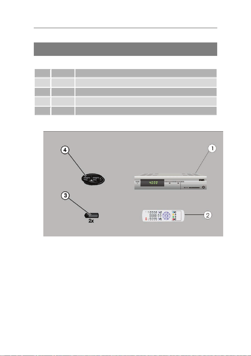
Package contents
Check the package contents after buying.
No. Amount Item
1 1 Digital satellite receiver
2 1 Remote control
3 2 Batteries (Type AAA, “Micro cells“)
4 1 SCART cable
4BPackage contents
9
Page 10

5BDescription
Description
With this equipment digital satellite channels can be received using a
satellite antenna.
The receiver does not need to be programmed, all programmes
transmitted at the time of delivery over the Astra, Hotbird and Turksat
satellites are already pre-programmed.
The channels transmitted by a satellite can be received as soon as
the receiver is connected up to an antenna pointing at a satellite. The
receiver searches for the channels as soon as the automatic search
function for this satellite is started.
All functions of the receiver can be operated using the remote control.
All receiver settings can easily be effected by means of the menu on
the TV screen. The on-screen menu supports the following
languages:
• German,
• English,
• Arabic,
• French,
• Italian,
• Russian,
• Spanish
• Turkish,
• Farsi,
• Dutch,
• Greek and
• Hungarian.
The receiver can update software over the Astra satellite.
10
Page 11

5BDescription
Additional features:
• OTA (satellite update)
• Integrated text decoder (STB/VBI)
• PIG (Picture In Graphics)
• 4000 channel storage positions (3000 TV and 1000 radio
channels)
• LNB control logic (13/18V, 14/19V, 0/22 kHz)
• SCPC/MCPC reception in C/Ku-Band
• Digital receiver with Loop-Through output for the second receiver
• Digital audio output (optical)
• Symbol rate 2–45 Mb/s and frequency range 950–2150 MHz
• DiSEqC 1.2 STAB USALS
• Manual PID-input
• Electronic channel guide (EPG) with direct channel selection
• Eight-colour On Screen Display (OSD) with 17 transparency
modes
• Four-digit LED-Display
• Screen format can be set to 4:3 or 16:9 (widescreen)
• Child lock and blocking function for individual channels
• RS 232 C-connection for additional information exchange and
updating the system software (socket)
• Timer (7-recording period, as desired
)
• Five lists of favourites
• Data transmission from receiver to receiver
• Integrated Cryptoworks interface
11
Page 12
6BOverview of the equipment
Overview of the equipment
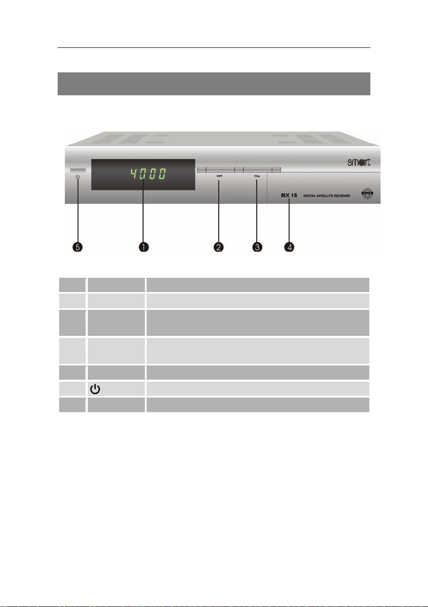
Receiver front panel
No. Symbol Function
1 LED-Display Shows channel number or time
CH▼
2
CH▲
3
4 – Cover for the Cryptoworks interface
5
Change down a channel,
move on-screen cursor downwards
Change up a channel,
move on-screen cursor upwards
“On” / “Standby” mode switch
12
Page 13
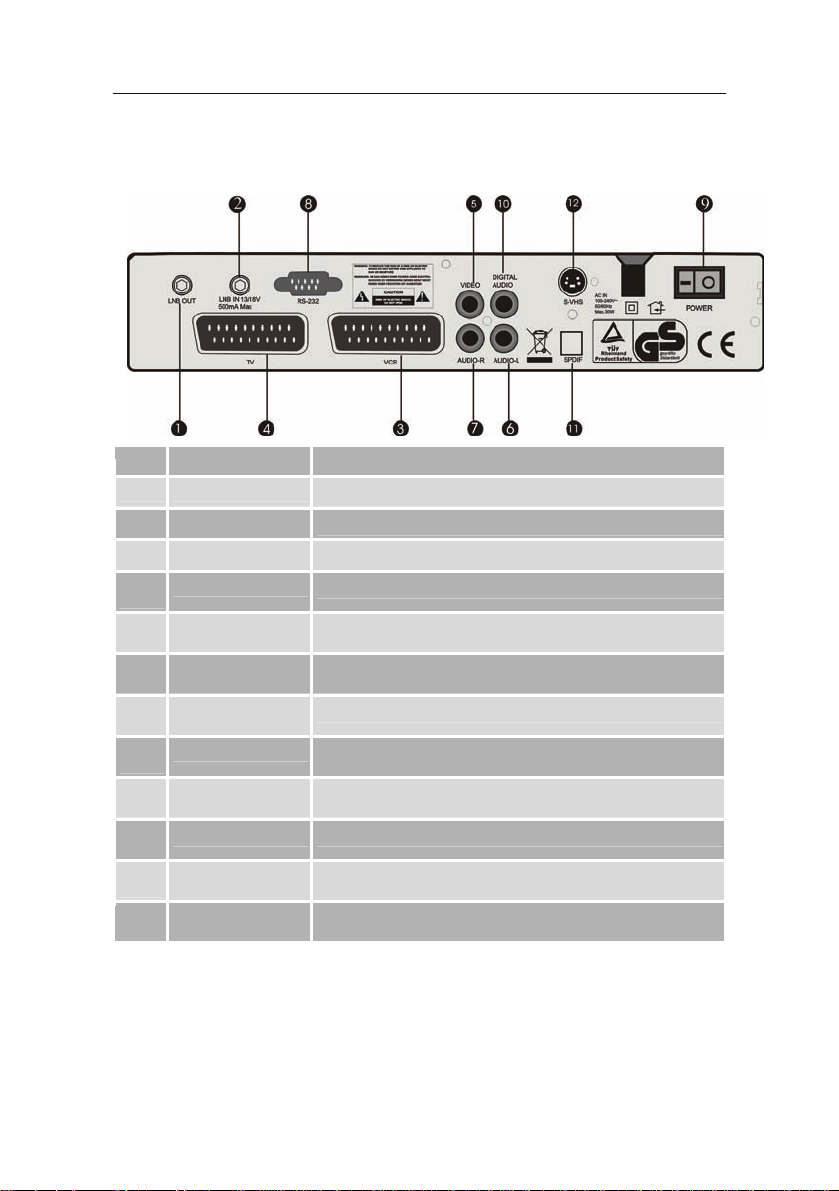
Receiver rear panel
No. Symbol Function
1 LOOP OUT
2 ANT INPUT
3 VCR SCART
4
TV SCART
5
Video
Loop connection for digital receiver
Connection for antenna cable
SCART-connection for video cassette recorder
SCART-connection for TV set
Video output, connection for video cassette recorder
6BOverview of the equipment
6
AUDIO L
7
AUDIO R
8
RS 232
9
0/I
10
DIGITAL AUDIO Digital co-axial audio output
11
SPDIF Digital optical audio output
12
S-VHS S-VHS connection
Analogue audio connection, left
Analogue audio connection, right
Serial interface
On / Off switch
13
Page 14
6BOverview of the equipment
Connecting up the receiver
The receiver is connected by means of an LNB cable to the
connection socket of the satellite antenna. Before connecting the
receiver an LNB cable may have to be installed.
L
An LNB cable is not supplied.
Danger!
The braided sheath and the internal conductor of the LNB cable
are under current during operation. Whilst operating, do not touch
the LNB cable. (Danger of injury through electric shock!)
Caution!
Before connecting up, remove all packaging from the receiver
otherwise the receiver could be damaged.
Caution!
Only connect up the receiver to the power source after all
equipment and the antenna have been correctly connected.
Otherwise the receiver could sustain damage.
14
Page 15

6BOverview of the equipment
Installing the LNB cable
For installing an IF plug on the co-axial cable wire strippers and
cutting pliers will be required.
Cut off 8mm co-axial cable down to the internal core at both ends.
Carefully cut 10mm of external isolation material off, so that the
braided sheath is showing.
Turn back the braided sheath and turn it over the outer isolation
material, ensuring that it does not touch the internal core
Remove the internal isolation material up to 2mm before the
braided sheath.
Turn the IF plug onto the turned-back braided sheath until the plu g
meets the internal isolation material..
L
The braided sheath should not protrude behind the end of
the plug.
Shorten the internal core with cutting pliers, so that it protrudes at
most 1mm out of the plug.
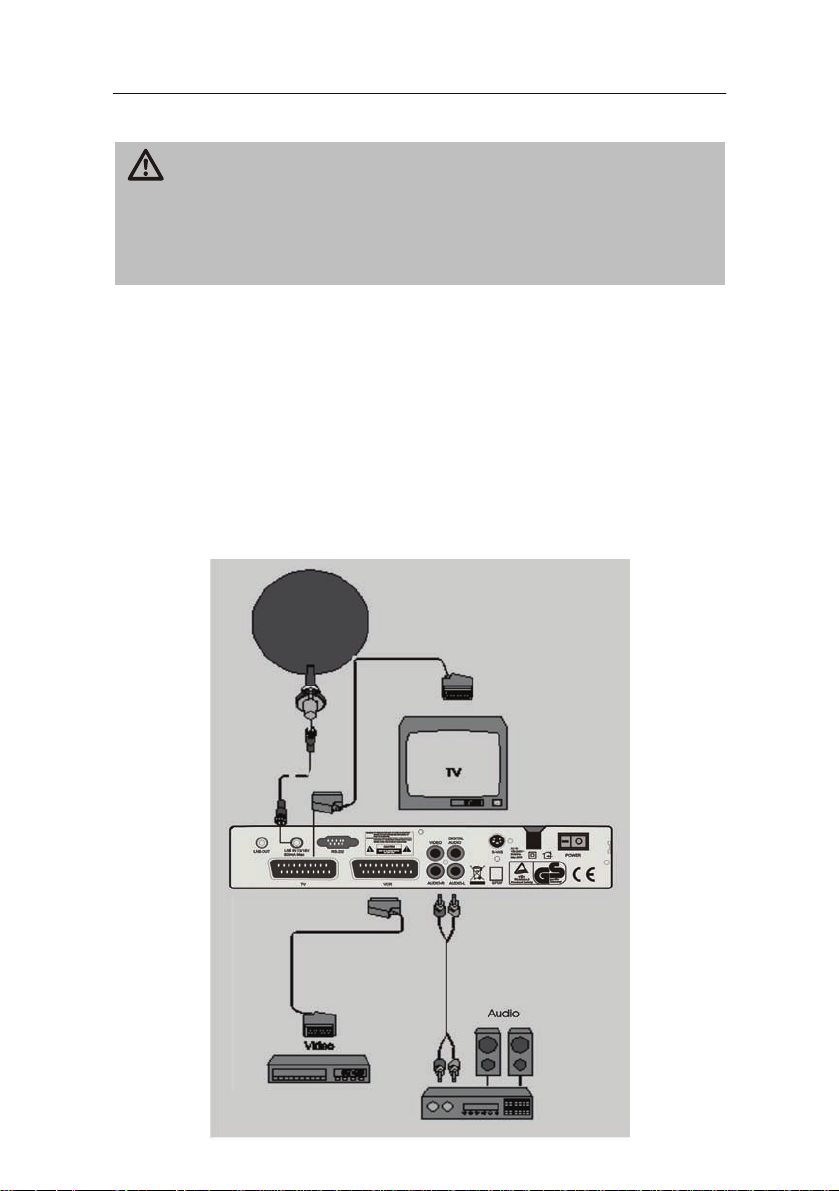
Connection of a SCART cable
Screw the IF plug of the LNB cable on to the receiver’s antenna
input marked “ANT INPUT“.
Plug the SCART cable into the receiver’s SCART connection
marked “TV“.
Connect the SCART cable with the TV set. Observe the operating
instructions of the TV set.
If a video cassette recorder is to be connected, then plug a
SCART cable in the receiver’s SCART connection marked “VCR”.
Connect the SCART cable with the video cassette recorder.
Observe the operating instructions of the video cassette recorder.
If a music centre is to be connected, then plug the cinch cable in
the receiver’s sockets marked “AUDO R” and “AUDIO L”.
15
Page 16
6BOverview of the equipment
Caution!
Never connect the phono input of the music centre to the receiver,
as this can damage the music centre. Do observe the instructions
regarding the connection of a cinch cable contained i n the
operating instructions of the music centre.
L
Cinch cables for audio and video are not supplied
Connect the cinch cable to the music centre.
L
Connection diagram with SCART cable
The TV set does not need to be switched on for radio
reception.
16
Page 17
6BOverview of the equipment
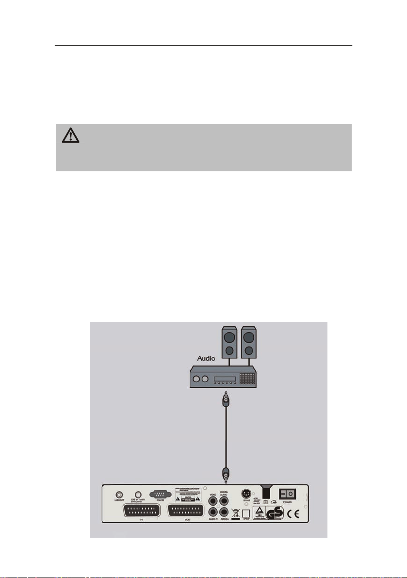
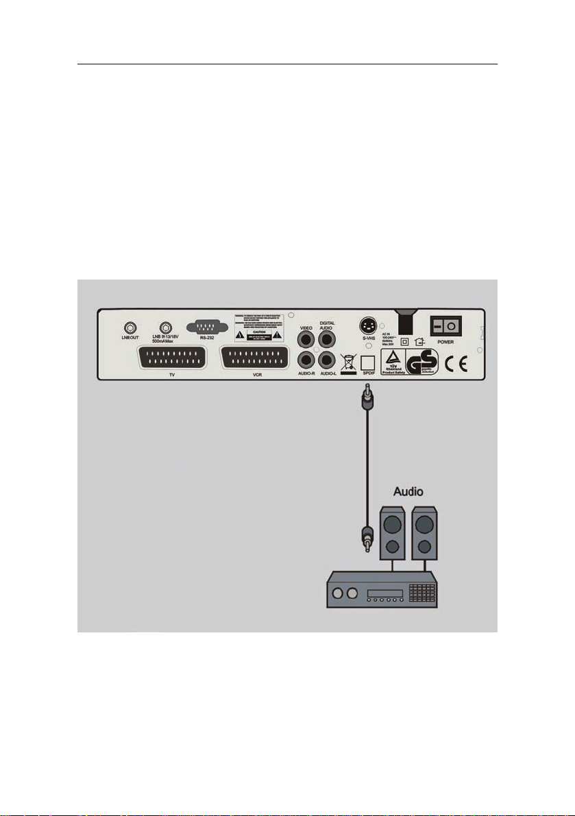
Connection of a digital audio receiver
If the 5-channel audio transmission (Dolby Digital Sound/AC3) is to
be used, then the digital audio receiver must be connected to the
optical or co-axial output of the receiver..
Caution!
Please observe the instructions regarding the connection
contained in the digital audio receiver’s operating instructions.
L
Connecting the co-axial digital output
An optical cable and co-axial cable are not supplied.
Remove the protective cap from the receiver’s socket marked
”DIGITAL AUDIO (CO-AXIAL)“.
Plug the optical cable in the receiver’s socket marked “DIGITAL
AUDIO (CO-AXIAL)“.
Connect the optical cable to the digital audio receiver.
Connection diagram
17
Page 18
6BOverview of the equipment
Connecting the optical digital output
Remove the protective cap from the receiver’s socket marked
”DIGITAL AUDIO (OPTICAL)“.
Plug the optical cable in the receiver’s socket marked “DIGITAL
AUDIO (OPTICAL)“.
Connect the optical cable to the digital audio receiver.
Connection diagram
18
Page 19
7BFirst steps
First steps
Switching on and off
To change from “standby” mode to “on”, press the “Power” button
on the remote control or on the receiver.
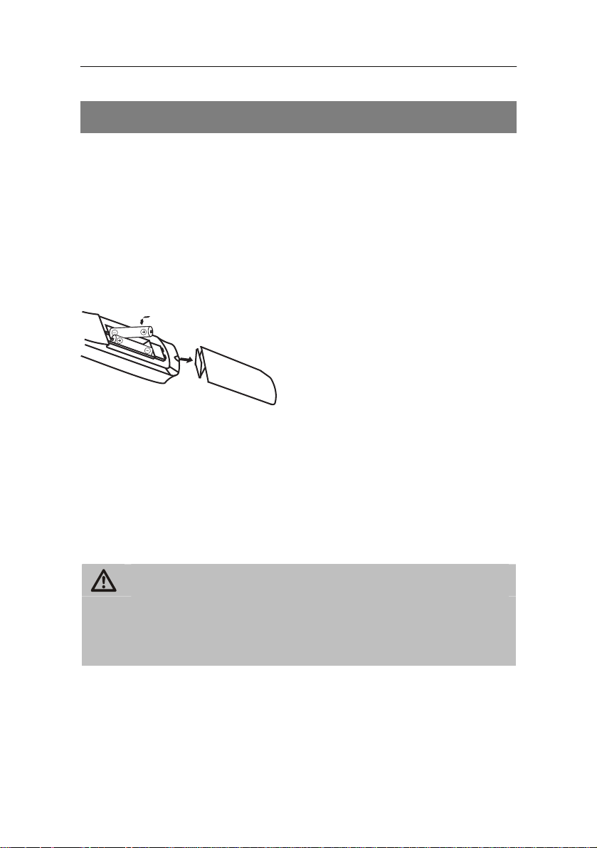
Remote control
Two micro batteries of designation LR 03 / AAA / 1,5 V are required
for the remote control
Open the battery compartment
Insert two batteries into the battery compartment, taking care that
the polarity is correct polarity. Close the battery compartment
cover carefully until the cover clicks in.
Replace weak batteries in good time.
Replace both batteries at the same time, and use batteries of the
same type.
When a battery is spent, put on a protective glove and clean the
battery compartment with a dry cloth.
Caution!
Batteries can contain poisonous substances, which can be harmful
to health and damage the environment. Please dispose of used
batteries in accordance with current legal regulations. Never throw
batteries away with normal domestic waste.
The remote control transmits infra-red signals to the receiver. Aim the
remote control at the front panel of the receiver and briefly press the
required button once.
19
Page 20

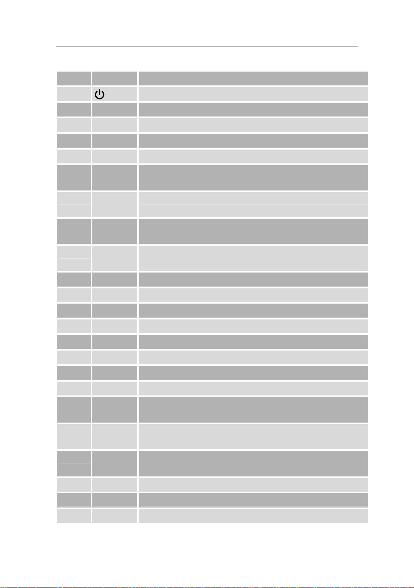
Remote control button functions
7BFirst steps
20
Page 21
7BFirst steps
No. Symbol Function
1
Switch “On” or change to “Standby” mode
2 RECALL Change to the previously selected channel
3 0-9 Direct channel no. selection, numerical input
4 TV Change over to TV mode
5 TXT Activates Teletext
6 VOL+
Increase volume
7 VOL-
Decrease volume
8 OK – confirm menu or menu item
– display channel list
9
X
– decrease volume
– move cursor to the left
10 Menu Call up or leave main menu
11 Setup Display set-up menu
12 FAV Call up list of “Favourites” (if already compiled)
13 (MUTE) Turn off sound
14 Radio Change over to radio mode
15 CH+ Step-up to next channel
16 CH- Step-down to next channel
17 INFO Display received data regarding current channel
18
S
– step-up to next channel
– move cursor upwards
19
W
– increase volume
– move cursor to the right
20
T
– step-down to next channel
– move cursor downwards
21 Lang Choice of desired audio mode or of menu language
22 EXIT Leave menu or menu item
23 EPG Electronic Programme Guide
21
Page 22

7BFirst steps
Receiver
Caution!
Check the connections of all equipment and the antenna are in
working order before connecting the receiver to the power source.
Insert the receiver’s plug in the power socket.
The receiver starts up in Standby mode. On the display the current
time is shown.
Insert the plugs of the auxiliary equipments in the power socket
and switch them on.
Select the AV channel on the TV set.
The receiver is delivered with pre-programmed TV channels and can
be used immediately. To see if there are any new channels, then
activate the channel search. Details are contained on page 30.
22
Page 23

7BFirst steps
Inserting a Smart Card
You can also view channels which have been encoded using the
Cryptoworks system by inserting the channel provider’s Smart Card.
Open the cover of the card slot.
Insert the Smart Card into the slot.
Caution!
If the Smart Card is incorrectly inserted, then this could damage
the receiver or the Smart Card.
Close the cover of the card slot.
Instructions for using the Smart Card software can be found on page
47.
23
Page 24

8BBasic settings
Basic settings
In order to take advantage of the entire spectrum of the receiver’s
functions, the receiver must first be configured.
Press the “SET UP“ button on the remote control.
The PIN number is now required.
Enter the PIN number (Works setting: 1234).
Changing the system settings
The following settings can be changed in the “System Settings”
sub-menu:
Setting Options Description
Video Format
TV Type Standard (4:3)
SCART/RGB On/Off Leave the setting at “On” if the
MULTI Works setting. The receiver switches
automatically to the television
broadcast standard being
transmitted. Only change the setting
if the TV set does not support the
indicated standards.
PAL I, PAL B, PAL G
or PAL K
SECAM SECAM is mainly used in France and
NTSC NTSC is a television broadcast
Wide (16:9)
PAL is one of the most common
television broadcast standards for
colour transmissions in Europe,
Australia and some Asiatic and
African countries.
Eastern Europe.
standard common in North America
and Japan.
Select a screen size from either 4:3
format or 16:9 format (Widescreen).
receiver is connected with a SCART
cable.
24
Page 25

8BBasic settings
Setting Options Description
Time zone Automatically set.
Positioner Yes/No “Yes“, if a motorised satellite
system is being used.
In this case the sub-menu “Motor
control” is displayed.
Summer time On/Off “Off” sets standard mean time, “On”
sets summer time.
Teletext Type STB/VBI “STB“ allows the calling up of
Teletext directly on the receiver.
“VBI” redirects the Teletext signal to
the TV set.
RAPS Scanning On/Off A description of RAPS can be found
on page 56.
Choose the desired settings.
25
Page 26

8BBasic settings
Changing antenna settings
In the “Antenna Settings” sub-menu the following settings can be
changed:
Setting Options Description
Satellite e.g.:
[019.2° E] Astra1
[013.0° E] Hotbird 1–5
LNB frequency
High L.O
Low L.O
22kHz impulse On/Off
DiSEqC
Universal
"Wideband“
OSC C-Band
C-Band
Ku-Band
These settings are
DiSEqC-A
DiSEqC-B
DiSEqC-C
The most common satellites are
pre-programmed. Additional
satellites can be inputted in
Chapter “Motor control” (see page
27).
These settings are
pre-programmed for the most
common satellites.
pre-programmed for the most
common satellites. The settings
can be altered using the numeric
buttons.
Here the individual satellites can
be allocated directly to a DiSEqC
position.
DiSEqC-D
Tone-A
Tone-B
Off
26
Page 27

Setting Options Description
8BBasic settings
LNB operation
H/V (Horizontal/Vertical)
Leave this setting at “H/V“.
The further settings are only
14V (Vertical)
relevant for single cable systems
or special in-house distribution.
18V (Horizontal)
Off (Aus)
Positioner
None
STAB USALS
DiSEqC 1.2
Settings for the motor control of
the satellite antenna. These only
apply to an antenna with
corresponding function (see page
27).
Choose the desired settings.
Motor control
Caution!
Leave the setting-up of the motor control to properly-trained
personnel. Otherwise the satellite equipment may not function
correctly.
L
In order to use this function, the satellite equipment must
possess a motor control.
Select the option “STAB USALS“ or “DiSEqC 1.2“ using the arrow
buttons “X" and “W".
Press the “OK“ button.
The following settings can be made in the “Motor Control” sub-menu:
27
Page 28

8BBasic settings
DiSEqC:
Setting Options Description
Satellite Select the desired satellite here.
Transponder The pre-programmed transponder
for the satellite are displayed here.
Move East<<< >>>West
The satellite can now be
turned into the desired
direction using the arrow
buttons “X“ and “W“ .
Save with ”Save Position“ and
„OK“ button.
Function
Reference
Position
Antenna Is automatically displayed.
Signal quality Is automatically displayed as a
Set west limit
Set east limit
Disable limit
Setting of limits for the Motor
Setting.
A starting point for the satellite
search function can be
selected by pressing the “OK”
button.
number and as a bar.
28
Page 29

8BBasic settings
Stab Usals:
Setting Options Description
Satellite Select here the desired satellite.
Transponder The pre-programmed transponder
for the satellite are displayed here
My Longitude
My Latitude
Move The satellite can now be turned in
Reference
Position
Signal Level Is automatically displayed as a
Signal Quality Is automatically displayed as a
Enter here the longitude on
which the satellite antenna is
located.
Enter here the latitude on
which the satellite antenna is
located.
the desired direction using the
arrow buttons “X“ and “W“ .
A starting point for the satellite
search function can be
selected by pressing the “OK”
button.
number and as a bar.
number and as a bar.
29
Page 30

8BBasic settings
Search for channels
The following settings can be made in the “Channel Search”
sub-menu:
Setting Options Description
Search Mode
Transponder
Frequency
Sat. (Free + Scr): Searches for all receivable satellite
channels, including encoded.
Sat. (Free): Searches for all unencoded
satellite channels.
TP (Free + Scr): Searches for all receivable
channels, including encoded, on a
specific transponder.
TP (Free): Search for all unencoded channels
on a specific transponder.
TP–NIT (Free + Scr): Searches all transponders
belonging to a group of channels.
TP–NIT (Free): Searches all transponders
belonging to a group of unencoded
channels.
Enter the transponder to be
searched..
The search is only possible in the
“TP“ or “NIT“ modes.
Enter the exact data to find the
channel.
Only possible in “TP“ or “NIT“
modes.
30
Page 31

Setting Options Description
8BBasic settings
Symbol rate
Polarity
FEC
Function
AGC Signal Displays the strength of the
Append
Delete
modify
Enter the exact data to find the
channel.
Only possible in “TP“ or “NIT“
modes.
Enter the exact data to find the
channel.
Only possible in “TP“ or “NIT“
modes.
Enter the exact data to find the
channel.
Only possible in “TP“ or “NIT“
modes.
Append, delete or modify settings
as a piece of data.
received signal.
If the TV picture is faulty, then
the antenna must be
re-aligned..
Choose the desired settings.
31
Page 32

8BBasic settings
Child lock/PIN-Code
The following settings can be made in the “Setup Child lock”
sub-menu:
• Set the child lock (menu block),
• Change the password
At the works the PIN Code “1234“ has been pre-set.
To call up a protected menu, the PIN code must be entered at the
prompt.
Enter the PIN code using the numeric buttons.
Each number entered is shown in a box in the input window as a star.
When the correct PIN code is entered, the selected menu opens
automatically.
Changing the PIN Code
The PIN code set at the works can be changed and any four-digit
number can be set as a personal PIN code.
L
Make a note of the new PIN code, as after changing the
code only the new number is valid. If the PIN code has been
forgotten, then please contact the manufacturer.
Select the menu item “Change password” using the arrow buttons
“T" and “S" or “X" and “W".
Press the “OK“ button.
Enter the new PIN code using the numeric buttons.
The display jumps automatically to the menu item “Repeat
password”.
Enter the new PIN code again.
The new password has now been accepted.
32
Page 33

8BBasic settings
Changing time settings
The following settings can be changed in the “Time Settings”
sub-menu:
Setting Options Description
Local time
Sleep timer 0 – 180 min.
Timer The receiver can be programmed so that at a
The timer is set in the following way:
Enter the current time in the following
format:
DD;MM;YYYY – Day – HH:mm.
Sets in 30-minute steps the time after
which the receiver switches itself off.
set time it switches over to a specified channel.
Up to seven timer functions are possible. This
function can be used, for example, to record a
programme on a video cassette recorder.
Change over to the “Status” bar.
Activate “On”.
Select at “CH Type“ TV or radio.
At “Channel No.” enter the number of the desired channel.
At “Channel Name” the name of the selected channel is displayed as
a check.
At “Start” enter the time at which the receiver should switch on or
over, and at “Duration” enter the length.
33
Page 34

8BBasic settings
Works settings
L
Call up the “Works Settings” sub-menu.
Select “Yes” if the receiver is to be returned to the works settings.
Select “No” to leave the menu.
If “Yes” has been selected, then the receiver automatically tries to
re-programme and update the channels using the RAPS system (see
page 56).
Wait until the receiver re-starts.
This process can take several minutes.
To return to the TV programme, press the “EXIT” button.
Here, the receiver settings are returned to the original works
settings as at delivery. All settings undertaken subsequently
and any stored data will be erased.
34
Page 35

9BOperation
Operation
Basic operating steps
Switching between radio and TV modes
L
To change between radio mode and TV mode, press either the
Selecting a channel
To change to the previous or subsequent channel, press the arrow
You can also press the arrow buttons on the receiver ”T“ or “S“.
L
Volume
To increase or decrease the volume, press the "VOL +“ or „VOL –“
Press the “Mute” button to switch off the sound.
If located in a menu, leave using the “EXIT” button..
“TV” button or the “RADIO” button.
buttons “T" or “S" or channel buttons “CH +“ or “CH –“
Switching to a desired channel can be done by directly
entering the channel number on the numeric buttons.
or the “X" and “W" buttons.
35
Page 36

9BOperation
Additional functions
Display additional information
The following information regarding the current channel can be
displayed:
• Channel (Name, position, settings, title of programme)
• Brief description of contents
To display additional information on the screen, press the “INFO”
button.
Each time the button is pressed the displayed information changes.
L
Display list of channels
To display the list of TV and/or radio channels press the “TV” or
Highlight a station using the arrow buttons “T" and “S" or “X" and
To change to the marked station, press the “OK” button.
To return to the selection menu, press the “EXIT” button.
Press the “TV” or “RADIO” button again to return to the normal
This function is only available if the station broadcasts the
relevant information.
“RADIO” button.
“W".
screen setting.
36
Page 37

9BOperation
Using the selection menu
The list of stations in the selection menu can be sorted or selected
according to various criteria. The list of stations of all satellites
received or those of a certain satellite can be displayed.
Select the satellite in the sub-menu “Sat” using the arrow buttons
“X" and “W".
Select the desired type of sort criteria in the sub-menu “List”:
Symbol Option
All (1.2.3..) All stations sorted numerically
All (A.B.C..) All stations sorted alphabetically
Free (1.2.3..) All unencoded stations sorted numerically
Free (A.B.C..) All unencoded stations sorted alphabetically
Select the desired channel using the arrow buttons “T" or “S".
Press the “OK” button.
Display list of favourites
To call up the list of favourite stations, press the “FAV” button
during operation.
L
This function can only be used if a list of favourites has been
created (see page 45).
To leave the list of favourites, press the “TV” button.
The list of stations is now displayed.
37
Page 38

9BOperation
Programme news
To display additional information regarding
• The current programme,
• The following programme or
• The programme of the selected station
Press the “EPG” button during operation.
L
Display Teletext
This function can only be used if the selected station
supports it.
To call up Teletext, press the “TXT” button during operation.
Enter the desired page number using the numeric buttons.
L
Choose language
This function can only be used if the current station offers
Teletext.
To display the menu for language options, press the “LANG”
button.
Select the desired language option using the arrow buttons “T" or
“S".
38
Page 39

9BOperation
The following language options can be set:
Menu option Option
1 of 1 (depending on station) Sound channel
2 (depending on station)
Mono
Level
Language Selected language will be displayed (depending on station)
Sub-title Show or hide sub-titles (depending on station)
Stereo
Mono left
Mono right
Normal
High
Low
Select the desired setting using the arrow buttons “X“ and “W“.
Recall
To call up the last channel selected, press the “RECALL” button.
On-screen user interface
Individual receiver setting preferences can be entered by means of
an on-screen user interface menu. The receiver and the TV set must
be switched on to display the user interface. This consists of the main
menu and sub-menus.
Press the “MENU“ button.
The main menu will be displayed.
Select the desired sub-menu using the arrow buttons “T" and “S"
and press the “OK” button.
The sub-menu will appear.
39
Page 40

9BOperation
Moving around the menus and sub-menus
To switch between the menu options, press the arrow buttons “T"
and “S" or “X" and “W" on the remote control.
L
The menu option selected will be displayed as black text.
To confirm the selected menu option, press the “OK” button.
The settings for this menu option will now appear.
Please read the messages at the bottom of the screen.
L
The on-screen display for most of the menu options is split
into two. On the left-hand side appears the name of the
setting. On the right-hand side the currently-set data is
displayed.
To spring from one setting to the next, press the arrow buttons "T“
and “S“.
The selected setting is highlighted.
To confirm the highlighted setting, press the “OK” button.
Options:
- Using the arrow buttons “X" or “W", the selection options can
be changed.
- Using the arrow buttons “T" and “S" the desired selection
options can be highlighted
- Using the numeric buttons figures can be entered, if the setting
calls for a numeric input.
To confirm the setting, press the “OK” button.
To return to the next higher menu level, press the “EXIT” button.
To leave the main menu, press the “EXIT” button again.
The on-screen menu closes and the screen reverts to TV or radio
mode.
40
Page 41

The menu layout
Sub-menu Menu options
Programme news
Channel
Listing
Language
Edit
Stations
Embedded
Software
Version
Radio mode/TV mode
Now & Next
Preview
Displays channels received sorted alphabetically
Menu language
Games
Radio Ch Logo
TV or radio stations
Move channels
Select favourites
Child lock On/Off
Delete channel
Add channel
Change channel data
General card information Crypto
Available entitlements
Shows information regarding receiver and currently
installed software.
9BOperation
41
Page 42

9BOperation
Programme news
The “Programme News” sub-menu allows switching between radio
and TV reception and to display information regarding the
currently-received station.
Select the “Programme news” sub-menu using the arrow buttons
“X" or “W":
• The mode symbol “
TV mode.
• “Now & Next“, to display information regarding the current
programme and following programme on the station being
received, or
• “Preview” to display the programme for the next 24 hours on
the station being received.
/ “, to change between radio and
Confirm the selection with the “OK” button.
Channel listing
Using this sub-menu the list of channels received, sorted
alphabetically, can be displayed and directly selected.
Select in the “Channel listing” sub-menu using the arrow buttons
“X" or “W" the desired first letters.
L
In the channel listing stations can be shown, which possibly
cannot be received. If these stations are selected, the
receiver will automatically switch to the list of receivable
stations.
42
Page 43

9BOperation
Language
In the “Language” sub-menu various functions can be selected:
• The screen menu language can be set,
• “Tetris“ or “Puzzle” games started, or
• The radio logo display can be switched on or off.
Highlight the desired function using the arrow buttons “T" and
“S".
Select the desired option using the arrow buttons “X" or “W".
Confirm the selection with the “OK” button.
The selected function will start or be stored, the on-screen display will
change to the menu.
Menu language
The on-screen menu can be displayed in the following languages:
• English, German, French, Italian, Spanish.
Optional, depending on software version:
• Arabic, Russian, Turkish, Dutch, Greek, Hungarian und Persian.
43
Page 44

9BOperation
Edit station
To quickly choose a station or to change the settings of stored
stations, select the “Edit station” sub-menu
Enter the password. This is set on delivery at “1234”.
To change between radio and TV mode, using the arrow buttons
“X" and “W" select the mode symbol “
Select the desired option using the arrow buttons “X" and “W" or
“T" and “S".
Press the “OK” button.
To return to the next higher menu, press the “EXIT” button
If changes have been undertaken, a prompt appears and asks if
these should be stored.
Select the option “Yes” to confirm the changes or “No” to reject the
changes, using the arrow buttons “X" or “W".
If a wrong input has been entered, proceed as follows:
To change to the next higher menu, press the “EXIT” button.
To delete the changes, select the option “No” using the arrow
buttons “X" or “W".
/ “.
Moving channel positions
The position of one or more stations can be changed to a different
position in the listing.
Select one or more stations as desired using the arrow buttons
“T" and “S" and press the “OK” button.
The selected stations are now highlighted with a coloured
background.
Repeat the selection process for the next station to be moved.
Using the arrow buttons select the station, before which the
previously selected stations are to be inserted.
To complete the action press the “Recall” button.
The highlighted stations are now inserted into the selected position.
All stations following on below are now moved downwards on the list.
44
Page 45

9BOperation
Selecting favourites
To make selecting favourite st ation s easier, these can be combined in
a list of favourites.
Using the arrow buttons “X“ and “W“ select the option “Select
favourites”.
Select the desired stations using the arrow buttons “X“ and “W“.
To include the station in the list of favourites, press the “OK”
button.
The “Favourite” field is now marked with a tick.
After marking all desired stations as favourites, press the “EXIT”
button..
Select the option “Yes” to adopt the changes, or
“No“, to discard the changes.
The station is now included in the list of favourites.
Child lock function On/Off
Stations can be blocked, for example, to stop children watching
programmes not considered suitable for them.
Select the desired stations using the arrow buttons ”X“ and “W“ or
“T“ and “S“, and highlight the option “Channel lock”.
Press the “OK” button.
Repeat these steps for each station to be locked.
The blocked stations can only be watched if the correct PIN code is
entered (see Section “Child lock”, page 32).
Deleting channels
Stations can be completely deleted from the list of stations.
Using the arrow buttons “X" and “W" or “T" and “S", select the
desired stations and highlight the option “Delete channels”.
Press the “OK” button.
Repeat these steps for the next station to be deleted.
Press the “EXIT” button.
If the query is answered with “Yes”, then the highlighted station i s
deleted and the main menu appears.
45
Page 46

9BOperation
Adding channels
Using this menu a station can be added to the list of stations, by
entering the corresponding information. Use this option only when
familiar with the digital satellite technology and the necessary
information is to hand. Information for the following parameters is
required:
• Satellite, Transponder, Frequency, Symbol Rate, Polarity, FEC,
Channel Name, Audio PID, Video PID, PCR PID
Select the option “Add channels”.
Enter the information regarding the station using the arrow buttons
“X" and “W" or “T" and “S".
Press the “OK” button.
Altering channel data
In this sub-menu information regarding stored stations can be
changed. The following information regarding the following
parameters can be altered:
• Station name
• Audio PID
• Video PID
• PCR PID
Use this option only when familiar with the digital satellite technology
and the necessary information is to hand.
Select the option “Alter channels”.
Enter the changes on the on-screen keyboard using the arrow
buttons “X" and “W" or “T" and “S".
Encoded “Crypto Embedded “Programme
Press the “Menu” button.
Select the ”Crypto Embedded“ sub-menu using the arrow buttons
”T“ and “S“.
Press the “OK“ button.
A selection menu with the following menu items will be now
displayed:
46
Page 47

9BOperation
Select the desired option using the arrow buttons ”T“ and “S“.
Press the “OK“ button.
Under the menu option “General Card Information“ there are various
options available.
Select the desired option using the arrow buttons”T“ and “S“.
To call up the desired option, press the “OK“ button.
Smart Card information (“Card label and Additional Info“)
If this option is selected, the following information regarding the Smart
Card is displayed:
• Designation (“Card Label“)
• Serial number (“Smart Card Address“)
• Expiry date (“Card Valid until“)
• Protection of minors activated (“Enable MR“) or not activated
(“Disable MR“)
Protection of minors (“Set Maturity Rating“)
Select the “Enable MR“ option in order to restrict access to
channels unsuitable for young persons, or
Select the “Disable MR“ option for unrestricted access to all
receivable channels.
PIN Code of the Smart Card (“Smart Card Pin Code Change“)
Using this option, the password of the Smart Card can be
• changed,
• enabled or
• disabled.
The menu option “Available Program Providers“ shows the channel
providers, for which the Smart Card is enabled.
47
Page 48

9BOperation
Software Version
Select the “Software Version“ sub-menu.
On the screen the following information will be displayed:
Display Description
Model name Receiver model
Build date Date of manufacture
Software version Current software version
System Software Update
Update RAPS
Config
Update system Software
With this option the receiver’s internal software can be brought up to
date.
L
Using the arrow buttons “T" and “S" select the option “System
Enter the PIN code.
On the screen two running bar graphics are displayed and the
receiver begins to search for new software. If the upper bar does not
move after ten minutes, the receiver is equipped with the up-to-date
software version.
This function is only available, if the Astra satellite is
received.
software” and press the “OK” button.
To discontinue the updating, press the “OK” button.
If the receiver is not equipped with an up-to-date software version
then the newest version will be automatically downloaded. The bar
graphic grows up to 100%. The receiver now processes the
downloaded data. This process can take up to 20 minutes. When the
processing is completed, the receiver asks if the update is to be
stored.
48
Page 49

9BOperation
Select the option “Yes” to install the update, or
“No“, to reject the update.
If the option “Yes” was selected, now go to the menu option
“Works settings” on page 34 and reset the receiver.
The software update is now completed.
Update software from receiver to receiver
The receiver’s internal software can also be updated with the help of
a second receiver..
Caution!
Only two receivers of the same type may be used, or else the
receivers could possibly be rendered unusable.
L
Only use a serial cable with 1:1 coupling (no null modem
cable!). When connecting from receiver to receiver the
following coupling is required: 1/4 cross wire, 2/3 cross wire,
7/8 cross wire, 5/5 1:1, 9/9 1:1, 6 open (“Loop-through
cable“). This cable can be obtained from a specialist dealer.
Take these instructions to the dealer.
Connect both receivers with a serial cable.
(RS-232C cable, cross-wired) through the RS-232C interface
(serial interface).
Switch on the receiver with the newest software (source receiver).
Switch on the receiver to be updated.
Caution!
Do not switch the receivers off during an update, otherwise the
receivers may not operate correctly.
Press the “Setup“ button.
Enter the PIN code.
The setup sub-menus will now appear.
Using the numeric buttons, enter the number 5732.
The TV now shows the “Box-to-Box Copy“ sub-menu.
Select the desired option using the arrow buttons “X" and “W".
To start the transmission press the “OK” button.
49
Page 50

9BOperation
The transmission starts an d the update is carried out. This process
can take several minutes.
To abort the transmission, press the “EXIT” button.
Switch the receiver with the updated software off and wait a few
seconds.
Disconnect the serial cable.
Switch on the receiver with the updated software again.
De-installation
Disconnect the receiver and the auxiliary equipment from the
power source.
Unscrew the LNB cable from the receiver.
Remove the batteries from the remote control, if the receiver is not
to be used for a long period of time.
Pack the receiver, the cables and the remote control in the box.
Store the receiver and all accessories in a dry and dust-free place.
Protect the receiver from frost.
50
Page 51

10BCleaning
Cleaning
Danger of electric shock!
No liquid must be allowed to get into the receiver. Never clean the
receiver with a wet cloth. Before cleaning disconnect the plug from
the power socket.
Caution!
Do not use abrasive cleaning liquids such as petrol or thinners.
These liquids could damage the surface of the housing, present a
fire hazard, or lead to a life-threatening electric shock.
Only clean the receiver housing with a dry cloth.
51
Page 52

Troubleshooting
Symptom Possible cause and remedy
11BTroubleshooting
The display does
not light up.
No sound or picture,
the receiver LED is
illuminated.
No sound or picture.
The TV set shows
no picture.
Poor picture,
Blockage problems
The power cable is not connected..
Plug the power cable into the power socket..
The power switch is not on.
Switch the receiver on.
The receiver is in Standby mode.
Press the “Power” button. The receiver switches itself on
and the programme appears on the TV screen.
The antenna is not directed at the satellite.
Align the antenna correctly.
No or only a weak signal.
Check the cable connection from LNB to receiver and from
receiver to the auxiliary equipments.
Align the antenna correctly.
The system is not correctly connected up.
Check the connection of the SCART or HF cable.
The TV set is not in AV mode.
Switch the TV set onto the corresponding AV input.
The antenna is not correctly aligned on the satellite.
The LNB is defective.
The remote control
does not work.
If, despite everything, a fault cannot be rectified, then please contact
a specialist dealer or the manufacturer.
The batteries are exhausted.
Replace them with new ones.
The remote control is not correctly directed.
Aim the remote control at the front panel of the receiver and
see that nothing is standing between remote control and
receiver.
52
Page 53

12BDisposal
Disposal
On no account dispose of the digital satellite receiver in normal
domestic waste. Local authorities will be able to advise on the most
environmentally-friendly method of disposing of the equipment. Hand
old batteries in at an appropriate collecting point.
53
Page 54

13BTechnical Data
Technical Data Technical Data
Receiver
Dimensions (L × B × H) 270 x 60 x 100 mm
Weight (without packaging) 1.6 kg
Operating temperature 0 ºC to +40 ºC
Storage temperature –40 ºC to +65 ºC
LNB/Tuner input
F-socket IEC 169–24
Input frequency range 950 MHz ~ 2150 MHz
Input level range –65 dBm to –25 dBm
LNB switch-over 14/18 V, max. 400 mA
LNB-switching signal 22 kHz, 0/12 V
DiSEqC-signal Version 1.2
Demodulator
Front-End Module QPSK
Input data rate 2 MS/s to 45 MS/s
SCPC- and MCPC-capable
Spectral inversion Automatic converting
System resources
Processor 32 bit, 60 MHz
SDRAM 8 Mbyte
FLASH 2 Mbyte
Video Decoder
Transmission speed Up to 15 Mbit/s
Video resolution (Video format) 720 x 576 (Pal), 720 x 480 (NTSC)
Screen format 4:3, 16:9
Data interface
Socket 9-pole, D-sub, max. 115 Kb/s
Remote control
Range Up to 7 m
Power
54
Page 55

13BTechnical Data
Power consumption Max. 30 W
Power supply 90 – 250 V alternating current, 50/60 Hz
Connections on the rear panel
Audio L/R 2 x RCA Cinch
Digital Audio output (S/PDIF) 1 x RCA Cinch, 1 x optical
Data interface 9-pole, D-sub
Digital Tuner Input IEC 169-24
Loop-Through digital tuner IEC 169-24
Video 1 x RCA Cinch
TV SCART RGB, CVBS, Y/C, Audio
VCR SCART CVBS, Y/C, Audio
55
Page 56

14BRAPS
RAPS
What is RAPS?
All currently-transmitted TV and radio channels are already sto red on
the receiver on delivery. RAPS (Receiver Automatic Programme
Search) updates the list of channels and allows the automatic
addition of new channels or the deletion of discontinued channels.
RAPS saves the effort of seeking and programming these changes.
When the receiver is switched on, RAPS checks if there are new
channels available. New channels are automatically included in the
channel listing and shown on the screen as such. When channels are
finally terminated, the corresponding places in the listing are also
automatically deleted.
Parallel to this a personal list can be drawn up (within the list of
favourites) or switch off RAPS at any time using the “Wo rks Settings”.
Automatic installation or update of RAPS
L
L
The search for new RAPS listings is only supported in TV
mode, not in the receiver’s radio mode. To search manually
for a RAPS listing or make subsequent changes in the
configuration of the RAPS system, switch to TV mode.
When RAPS is utilised, the existing channel listing will be
overwritten.
To activate RAPS on the receiver, return the receiver to the Works
Settings (see page 34).
After doing this a prompt is displayed on the screen.
To use RAPS, select the option “Yes” with the arrow buttons “X"
or “W".
Press “OK“.
The receiver now searches for an up-to-date RAPS listing and then
displays the following information:
56
Page 57

14BRAPS
RAPS date receiver: Date of RAPS listing stored on the receiver.
Date: Date of the current RAPS listing available via satellite.
Satellites: Number of satellites integrated in the RAPS listing.
Transponder: Number of transponders integrated in the RAPS listing.
Channels: Number of channels available in the RAPS listing.
Press the “OK” button to load the newest RAPS listing
or press the “EXIT“ button to leave the menu.
The progress of the updating can be seen in a bar graphic on the
display.
After this a selection menu of the receivable satellites is displayed.
Select the satellites to be received over the receiver using the
arrow buttons “T" and “S" or ”X" and “W".
Confirm the selection by pressing “OK“.
In the space in front of the satellite selected a tick will now be shown.
Repeat the previous steps for all the desired satellites.
Then highlight the “OK” selection bar using the arrow buttons “T"
and “S" or “X" and “W".
Press the “OK” button again.
The available RAPS files are now displayed in the listing.
To select the best listing, press the arrow buttons “T" and “S".
Press “OK”.
57
Page 58

14BRAPS
Tuning in local TV stations
In the following menu option a decision for a regional TV channel is
required. In Germany that would be the regional third channels. If the
choice falls on the listing for Austria, then the ORF-2 regional channel
(e.g. ORF-2 Tyrol or ORF-2 Carinthia) to be stored must be selected.
The available regional TV stations will be displayed in a listing:
Select the regional TV station desired using the arrow buttons “T"
and “S".
Press “OK”.
Then a prompt appears “Do you want to see channels with erotic
content?”
Select the desired option using the arrow buttons “X" and “W" .
Press “OK”.
Hiding foreign language stations
In order to keep the channel listing easy to read, foreign-language
stations can be hidden.
Select the option “Yes” with the arrow buttons “X" and “W" and
confirm the selection with “OK” to hide the foreign language
transmissions.
A selection menu is now displayed, in which the languages to be
hidden can be selected.
Select the “OK” space of the non-desired languages using the
arrow buttons “T" and “S" or “X" and “W".
Press the “OK” button.
In the space in front of the marked foreign language a tick is now
displayed.
Repeat these steps for all desired satellites.
After finishing making the selections, mark the “OK” space using
the arrow buttons “T" or “S" and “X" or ”W".
Press the “OK” button.
The settings are now stored.
58
Page 59

14BRAPS
Switching the automatic check of the RAPS listing on and off
RAPS is set, so that after switching-on the receiver automatically
checks if a new RAPS listing with changed transmitter data is
available. The check lasts about 15 seconds.
The check can be stopped by pressing the “EXIT” button. If the
automatic update process is not required, then proceed as follows:
Press the “SET UP“ button and enter the PIN code using the
numeric buttons.
Select the sub-menu “System Settings” using the arrow buttons
“T" or “S".
Select the menu option “RAPS Scanning” using the arrow buttons
“T" or “S".
Select the menu option “Off“ to turn off the automatic check
using the arrow buttons “T" or “S" or
The option “On” to turn the automatic check on again.
Select the menu option “System Settings”. Here is found the
option “RAPS Scanning”.
Press the “OK” button.
If “Off” was selected, the message “checking RAPS date” will not
appear, and the receiver switches directly to the last channel listing
stored.
Manual check of the RAPS listing
If the automatic check of the RAPS listing has been switched off, then
an update can be carried out manually.
Press the “MENU” button and select the sub-menu “Software
Version” using the arrow buttons “T" or “S".
using the arrow buttons “T" and “S" or “X" and „W" select the
menu option “Update” in the “RAPS” sub-menu.
Press the “OK” button.
Enter the PIN code using the numeric buttons.
The current settings for RAPS will now be displayed and the receiver
checks if a new RAPS listing is available. If the data in the fields
59
Page 60

14BRAPS
“RAPS Date Receiver“ (listing on the receiver) and “Date“ (newest
listing) are different, the RAPS listing has changed. In this case, carry
out an update as follows:
Press the “OK” button to load the new listing onto the receiver.
Proceed as described above. If the RAPS listing has not changed,
then the message “No changes found” will be displayed.
Confirm with the “OK” button to return to the “Software Version”
sub-menu.
Subsequent alteration of the RAPS settings
To alter the RAPS settings (for example, the hidden foreign language
stations) proceed as follows:
Press the “MENU” button and select the sub-menu “Software
Version” using the arrow buttons “T" or “S".
Select the menu option “Config” in the “RAPS” sub-menu using
the arrow buttons “T" and “S" or “X" and “W".
Press the “OK” button.
The menu “Automatic Programming” will be displayed.
Enter the RAPS settings as described above.
60
Page 61

Service
WELA electronic Hand els GmbH & Co. KG
Industriestraße 29
D-78112 St.Georg en
Service Hotline: 00 49 1805 / 93 52 11
Telefax: 00 49 7724 / 94 78 333
E-Mail: info@smart-electronic.de
Internet: www.smart-electronic.de
Warranty
The guarantee for the Smart digital satellite receiver manufactured by
WELA electronic Hand els GmbH & Co. KG is in line with the legal
requirements at the time of purchase.
61
Page 62

Declaration of Conformity
WELA electronic Hand els GmbH & Co. KG hereby declares that this
product conforms to the following guidelines and standards:
Low-voltage guideline 73/23/EWG
• EN 60 335-1
• EN 60 335-2-15
Guideline pertaining to electro-magnetic tolerance 89/336/EWG
• EN 55 013:2001
• EN 55 020
• EN 61 000-3-2:2000
• EN 61 000-3-3:1995+A1:2001
• EN 61 938
Type of equipment/Type: Digital Satellite receiver
WELA electronic Handels GmbH & Co. KG
62
 Loading...