

Page 1

Copyright 1995 by SMART Devices Inc.
5945 Peachtree Corners East
Norcross, GA 30071-1337
Table of Contents
SECTION 1 INTRODUCTION..............................................................2
SECTION 2 CARD DESCRIPTION......................................................3
SECTION 3 INSTALLATION.................................................................7
-
WIRING HOOKUP INSTRUCTIONS.................................7
SECTION 4 CALIBRATION..................................................................10
- B CHAIN CALIBRATION.................................................10
- A CHAIN CALIBRATION.................................................12
SECTION 5 OPERATING INSTRUCTIONS.........................................13
SECTION 6 SERVICE..........................................................................13
SECTION 7 SCHEMATICS ..................................................................16
LIMITED WARRANTY: SMART products and accessories are warranted against malfunction or failure due to defects in workmanship or
materials for a period of one year from the date of shipment. If a problem occurs during the warranty period, the unit will be repaired, or
replaced at our option, without charge for materials or labor. If air freight is requested by the dealer, the difference between air and surface
charges will be billed to the dealer. This limited warranty does not cover products that have been abused, altered, modified, or operated in
other than specified conditions. Prior factory approval is required on all returns. Returned equipment or defective parts must be shipped
freight prepaid to us by the dealer or customer.
Our limited warranty does not cover damages resulting from accident, misuse or abuse, lack of responsible care, or failures not attributable to
manufacturing defects, except as provided herein. SMART Devices, Inc. makes no warranties, express or implied, including warranties of
merchantability or fitness for a particular purpose.
RETURN POLICY: Factory authorization MUST be obtained before returning any product. A 15% restocking charge will be issued on unused
equipment (in original box) that is returned for credit. Credit is issued to the dealers account. The credit may be used against future purchases
and no cash transactions are offered. All returns must be shipped freight prepaid by the dealer. Equipment returned without a factory RA
(Return Authorization) will be refused.
SMART products are designed to deliver unsurpassed quality in workmanship and performance. The following information gives detailed instructions on the installation and operation of the SMART MOD V processor. We strongly encourage new owners of the MOD V to
thoroughly read this entire manual before placing their new SMART product into service.
This will ensure that the MOD V will be operated properly to give the superior performance
that it was designed to deliver.
For service or installation assistance, please call our
Technical Support Department between the hours of
8 a.m-5 p.m. E.S.T., Mon.-Fri.
1-800-45-SMART
Page 2
2
INTRODUCTION
The MOD V Stereo cinema processor is a full 8 channel
system delivering superior audio quality for any theatre.
This advanced processor comes standard with many features, yet is easy to operate, making the unit the best buy on
the market. The MOD V is fully compatible with all digital
formats, and was designed to easily process 70mm and
35mm magnetic soundtracks.
To achieve optimum results from your new MOD V cinema
processor, the theatre engineer installing the system should
be totally familiar with all features and adjustments. Careful
attention to detail and familiarity with the installation
instructions will allow you to offer a system that has a
sound quality second to none.
FEATURES
In addition to the standard features you find on other
processors, the MOD V offers many extras that makes operation easier and more flexible.
FADER CONTROL:
To begin, the MOD V has one MASTER FADER that controls the overall playback level for all 8 channels. This master fader is used as the volume control for all formats except
music mode. Seven trim controls on the front panel independently fine tune adjust (± 3 dB) the volume level of each
format. The music control on the front panel is the master
music level control. The trim faders allow matched levels
when the MOD V transitions between various formats. This
unique feature allows the MOD V to operate without constant attendance by a projectionist.
STATUS INDICATORS:
The operator control panel features a STATUS DISPLAY
readout that shows the mode the system is in at any time.
Red LED’s show which format is selected. The indicator
lights can be seen from a distance so it is not necessary to
be near the processor to verify the status. LED arrays on the
front panel indicate relative volume level for the five primary channels: Left, Center, Right, Left Surround and Right
Surround.
UPDATING FOR THE FUTURE:
Since the MOD V processor is totally modular, any new circuit developments or additional options may be added easily. This can be achieved by simply plugging in a new card
into the existing card cage when a factory exchange or
update promotion is offered. The system can stay up with
current and future technology at minimum expense.
MOD V COMPONENTS:
There are two main components included in the MOD V
system: the power supply and the card cage. There are also
several optional plug-in cards to give the system more features and greater flexibility. The system cannot operate
without the two main components, but can operate without
the options.
— POWER SUPPLY:
A heavy duty fully-regulated power supply is furnished with
the MOD V processor. This bipolar supply is heavily filtered and supplies ample current for both the positive and
negative 20 VDC supplies. This external power supply minimizes the chances of hum pickup when high gain electronic
circuits are placed in the same chassis as a power supply.
Also, the large power capacity of the supply provides a very
“stiff” voltage to all cards in the MOD V to prevent power
sag (momentary drop of the supply output due to heavy
loads). This gives excellent transient peak response and
superior stability.
— CARD CAGE:
The “working” part of the MOD V system is housed in a
card cage rack mount assembly that contains plug-in component cards for easy servicing and future expansion of the
system. A theatre may elect to start with a basic OPTICAL
STEREO sound system, update to a digital stereo system,
and eventually an eight channel system with sub-woofer.
The SMART MOD V is fully equipped to handle your
expansion needs. The MOD V will easily handle magnetic
soundtracks with the addition of external magnetic preamps
and two more noise reduction cards that easily plug into the
main card cage.
Installation and Service Manual
MOD V Digital/Optical Stereo Cinema Processor
Page 3
3
INSTALLATION & OPERATION
CARD DESCRIPTION
Each circuit card in the MOD V has its own on-board voltage regulators that stabilizes the circuits locally as well as filter
unwanted signals that may be present on the main power busses.
Test points are included on some cards for the sound engineer to access vital circuit points with his scope or meter. These
terminals will accept a meter probe or “alligator” clip.
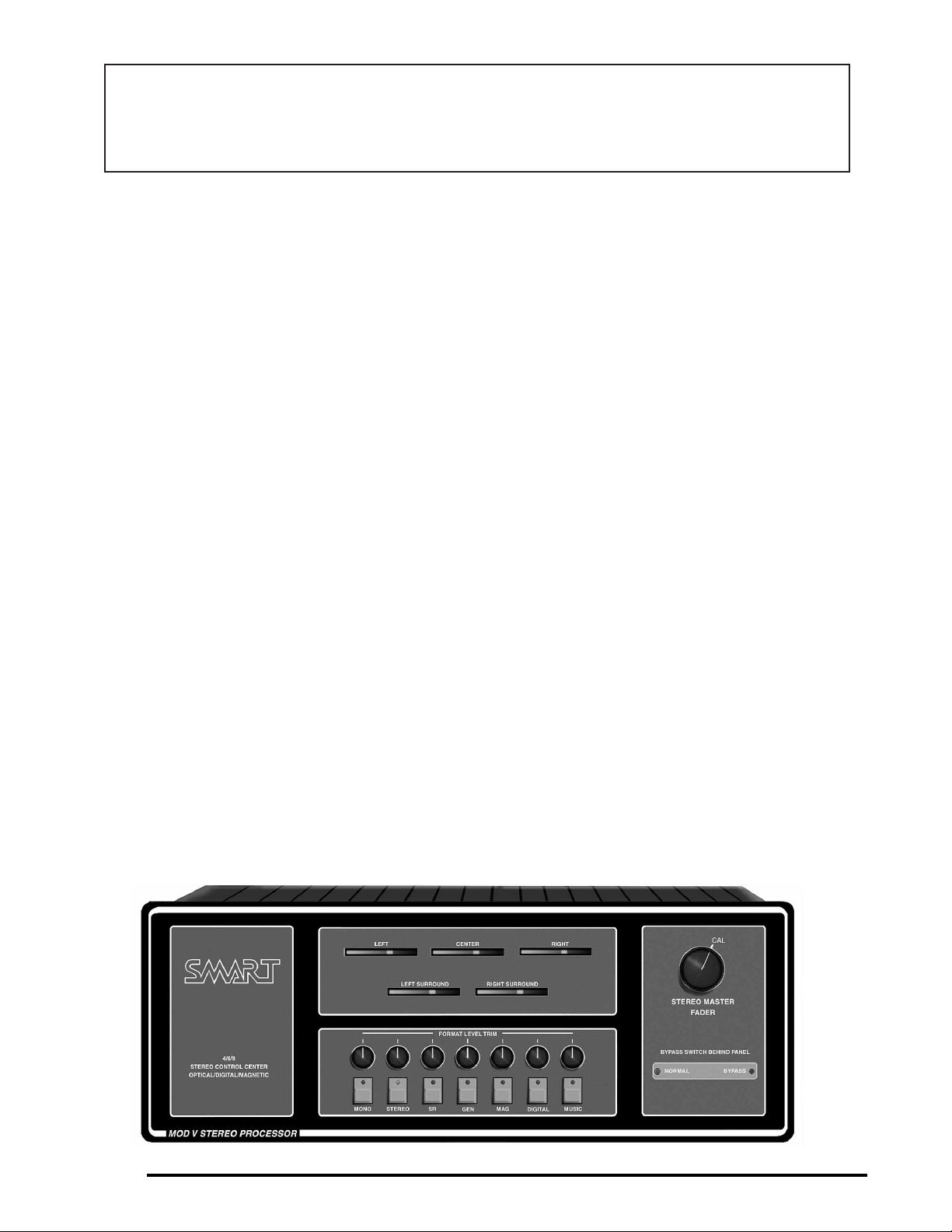
FRONT DISPLAY CARD:
MOD5X380
The front panel is where the Master Film Fader and individual Format Trim Level controls are located. This important card
has three switches (located on the inside of the unit) which are used for selecting various modes. To access these switches,
just pull the front panel forward from the top. The hinged front panel allows easy access to these switches.
The NULL switch is used during setup to change the LEFT SURROUND LED ARRAY circuit to indicate when a proper
surround null has been achieved. It should normally be left in the OFF position. The VOLUME switch selects either local
volume control or remote volume control. The third switch (only on the “C” version or later of the circuit board) is the
MAGNETIC NR switch which is used to select Type A or Type SR noise reduction for MAG prints. This switch is normally
set to MAG A.
Test points 1-3, located on the front right hand side of the board, is where you will find a convenient location for probing the
left and right outputs of the preamp card. The four red LED’s next to the preamp test points are used for setting preamp levels during setup.
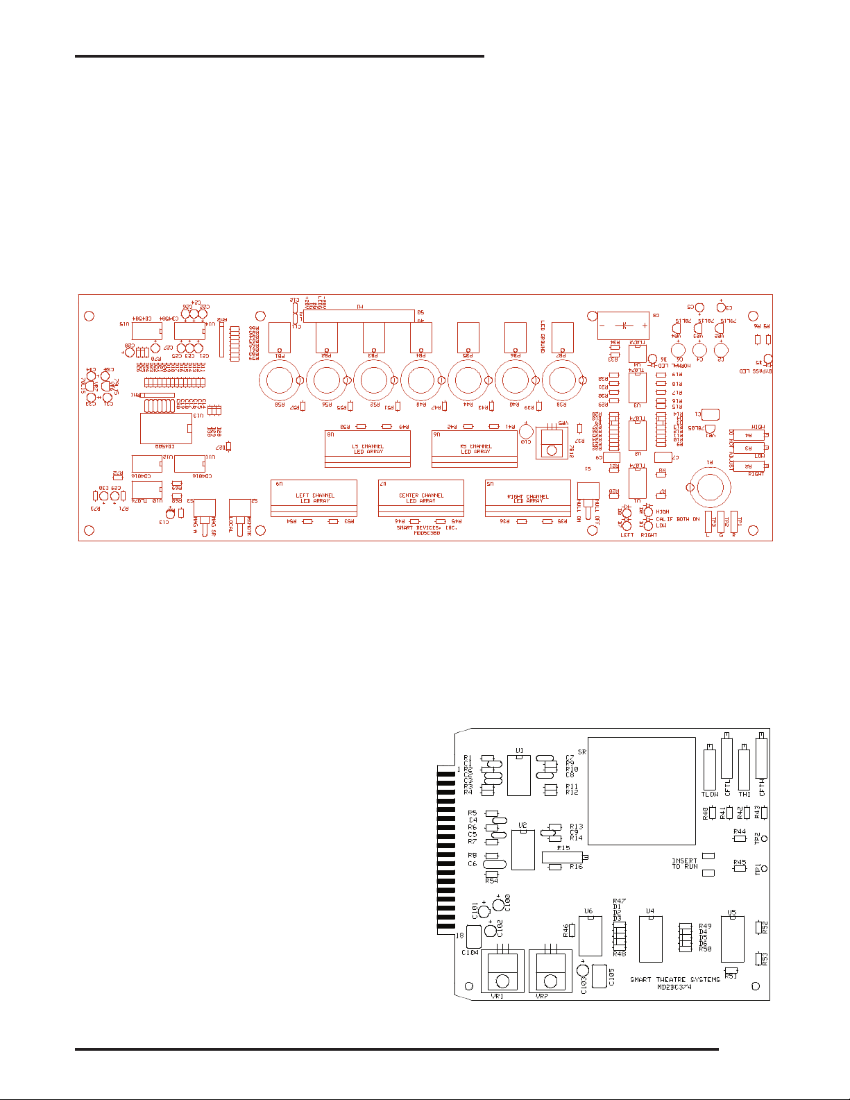
NOISE REDUCTION CARDS:
MD2BX374
The SMART noise reduction cards provide noise reduction
for decoding Dolby type A stereo prints and Spectral
Recording (SR) encoded prints. The noise reduction circuitry
is automatically switched to the proper mode when selected
by the format switches on the front of the processor. There
are four trimpots and two test points on each NR card. These
are for factory use only. Do not attempt to adjust these
trimpots or use the test points. Two of the NR cards (slots 1
and 2) are dual purpose. They are used for both optical
stereo and for mag soundtracks, left and right channels. The
other two cards (slots 3 and 4) are strictly for mag use only,
center and surround channels. These two are optional and are
not shipped with every MOD V, since they are only used for
sound systems equipped for magnetic prints.
Page 4
4
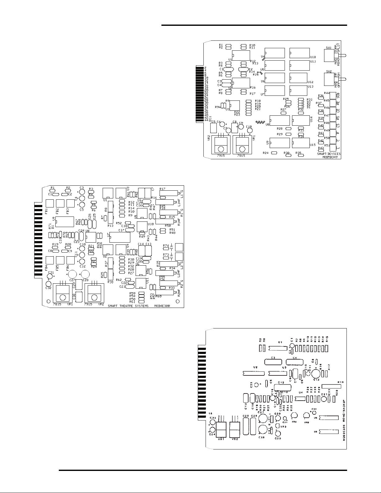
EXTERNAL INPUT/NR SWITCHING CARD:
MOD5X349
This card handles several functions related to external magnetic and digital signal sources, NR switching, and magnetic modes. Source selection of digital or magnetic signals is
provided by electronic switching I.C’s. These determine
which signals appear on the main signal busses of the MOD
V. This is dependent on which format is selected. The Left
and Right NR cards are switched between optical and mag
sources, again dependent on the selected format.
This card also has 2 toggle switches to select various magnetic sound modes. The bottom switch selects MAG NR
ON or OFF. Since most mag prints use NR encoding
(Dolby 70), this switch is normally ON (up position). The
top switch selects mag mono surrounds or split surrounds.
Because most mag prints do not have split surrounds, this
switch should normally be left in MONO (down position).
DUAL PROJECTOR PREAMP CARD:
MOD4X300
There are 2 stereo solar cell preamplifiers in the MOD V:
each preamplifier channel is equipped with slit-loss correction. The Stereo-optical preamplifiers on this card increase
the incoming level from the stereo solar cells. Electronic
changeover circuitry between stereo pairs is built on the
card to allow use in dual projector booths. If the MOD V is
installed in a single projector booth, leave the second projector inputs unconnected.
The Dual Projector Preamp Card has two solar cell preamplifier gain controls and two slit-loss correction circuits for
each projector. There is sufficient gain built into the preamps for narrow slit optical sound lenses when the exciter
lamp is run at 80% of its rated value. The card is silk
screened to make it easier to see the location of each preamplifier gain and slit-loss correction control pot.
MONO/BACKUP CARD:
MOD2X305
The MONO card provides the necessary frequency response
shaping and level shifting to provide a quality mono signal
from mono prints. In addition, a special open ended noise
reduction circuit called Dynamic Noise Reduction is used to
eliminate much of the “hiss” and film scratch noise often
present on film. This card also provides the necessary drive
signal for the optional stereo synthesizer portions of the
MOD V.
The MONO card contains the necessary circuitry for the
emergency backup system in the event of loss of sound
within the MOD V processor. The multi-turn pot on this
card is for setting the emergency backup level.
Page 5
5
INSTALLATION & OPERATION
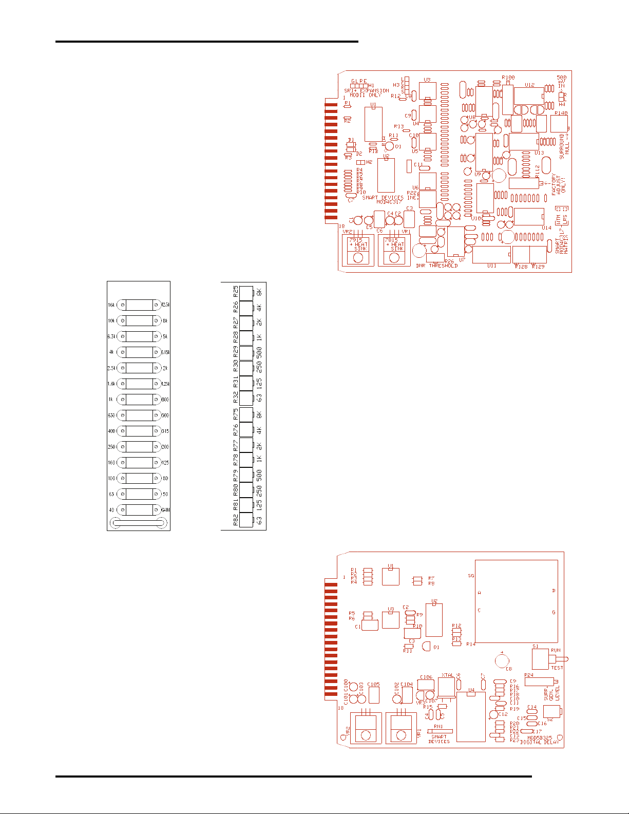
MATRIX CARD:
MOD4X317
This is the heart of the stereo conversion process. The Wide
Trac Deluxe Matrix card takes the signal from the preamp
and noise reduction circuits and converts the two channel
soundtrack into the four channels required for normal stereo
mode. There is a surround null adjustment trimpot on the
matrix card which the installer can adjust to minimize surround channel crosstalk without disturbing the input signal
calibration settings of the preamplifier and noise reduction
circuits.
1/3 OCTAVE EQUALIZER CARDS:
MOD4X320
Three one third octave room tuning equalizers are used for the
front stage speakers. Each adjustable frequency band in the
front stage EQs may be cut or boost ± 10 dB. A +6 dB gain
adjustment is also on each card. For overall unity gain, leave the
gain pot in the CCW position. For unity gain on each of the frequency band adjustments, leave the pot in the mid position. All
pots are the single turn type.
DUAL CHANNEL ONE OCTAVE EQUALIZER CARD:
MOD4X324
This card is for the Left and Right Surround Channels. Circuitry
and operation is similar to the stage channel EQs except that it
uses one octave EQs and there is no gain adjustment pot. The
top eight trimpots are for Left Surround, and the bottom eight
are for Right Surround.
DIGITAL TIME DELAY/SURROUND GENERATOR
CARD:
MOD5X325
The digital time delay portion of the MOD V system is contained on this card, along with the optional Stereo
Generator Surround Module. The surround channel passes
through the time delay whenever any Stereo-Optical format
or Stereo Generator format is selected by the operator.
35mm magnetic, 70mm magnetic, Music or digital inputs
are NOT time delayed. There is a rotary switch on this card
that is used to set the time delay setting. The rotary switch
has 16 positions: 0-9 & A-F. Position 0 is 10 milliseconds
of delay, which is the minimum delay setting. Each position
clockwise adds 10 milliseconds of delay for a maximum
setting of 160 milliseconds (position F).
Note: Earlier units used an analog time delay card. This
card had dip switches that set the time delay. All switches
down (on position) produced a minimum delay of 35 milliseconds. Each dip switch flipped up (off position) added
10 milliseconds of additional delay.
1/3 Octave EQ One Octave EQ
Page 6

6
OUTPUT/MUSIC CARD:
MOD5X331
Eight channels of audio, comprised of the primary stereo
channels (Left, Center, Right, Sub, Left Surround and Right
Surround), along with the Left-Extra and Right-Extra channels, pass through the MASTER VCA (Voltage Controlled
Amplifiers). The digital inputs also allow for separate Left
Surround and Right Surround channels in addition to a separate subwoofer input. The VCAs exhibit very close tracking between channels and are controlled by the MASTER
FILM FADER and individual FORMAT LEVEL TRIMS
contained on the front panel. Music Fade-in and Fade-out,
controlled by the automation or front panel format switch,
is also on the output card along with a special music matrix
to generate a four channel non-sync sound from a standard
two channel music tape or CD player.
FRONT STEREO GENERATOR CARD (optional):
MOD2X340
A deluxe Stereo Generator (synthesizer) is offered as an
optional feature of the MOD V system. The synthesized
front channel circuits are included on this card. The optional
surround generator is part of the DELAY/SURROUND
GENERATOR card in another part of the system. The output levels for the three stage synthesizer channels should be
adjusted ONLY after the main stereo-optical channels have
been correctly adjusted. The synthesizer levels should be set
to be the same as other stereo channels so that a transition
between film format modes will appear smooth to the audience without large level changes. Three multi-turn pots are
located on the front of the Stereo Generator PC board to
adjust the Left, Center, and Right channel outputs.
SUB WOOFER/BASS EXPANDER CARD:
MOD5X346
The last PC board on the far right of the MOD V card cage
contains the subwoofer output circuitry and the EMERGENCY BYPASS switch. Switching the MOD V into
emergency bypass mode is as simple as flipping the red
bypass switch. The bypass audio level is set by a multi-turn
pot on the Mono Backup card.
This card is equipped with an optical expander circuit that
works only when optical sound formats have been selected
(Stereo, SR & Stereo Generator), and not on Magnetic,
Digital inputs, or non-sync music. The small ON-OFF toggle switch on the front of the PC board turns the subwoofer
circuit on or off. The Sub-Bass optical expander expands
the output level at a 1.5 to 1 ratio in the low frequencies.
The Sub-Bass card is equipped with a five band 1/3 octave equalizer. The frequency adjustments are 31, 40, 50, 63 and 80
Hz. This gives good coverage of the sub-bass region.
Page 7

7
INSTALLATION & OPERATION
Bandpass shaping for the low frequency subwoofer output is selectable with various settings of the DIP switches at the front
of the PC card. The High Pass filter has a fixed slope of 12 dB/octave, and the Low pass filter is 18 dB/octave. The following
combinations of switches will configure the filters for the desired LF bandpass output.
DIP SWITCH SETTINGS FOR VARIOUS FREQUENCY BANDPASS CHARACTERISTICS
ALL switches UP for wide-band frequency response. Useful when feeding a sub-woofer power amplifier that has built-in filters.
ALL F1 switches DOWN - ALL other switches UP for 10-65 Hz
response to sub-woofer output.
F2 switches DOWN with ALL other switches UP will give a 10-200 Hz
response.
ALL F1 switches and HPF (high pass filters) DOWN, with F2 switches
up for 25-80 Hz frequency response.
ALL F2 and HPF switches DOWN with F1 switches up results in 35225 Hz bandpass.
If ALL DIP switches are set to the DOWN position, the output response
will be 23-68 Hz.
The Subwoofer/Bass expander card has individual output level adjustments for
Optical, Digital, Magnetic, and Music Formats. Each format sub-bass level may be set separately.
PROCESSOR PLACEMENT IN THE RACK:
Before mounting the MOD V processor in the equipment
rack or projector console, be sure to select a well ventilated
area that allows cool air to circulate around the individual
components. In SMART prewired rack systems, the Power
Supply is mounted on the floor of the rack, and the rackmounted processor is placed at eye level for easy visibility
of the system operation status.
Make sure that the processor is not immediately adjacent to
hum producing components. Run the factory-supplied
power supply wiring harness along the left side of the
equipment cabinet (when viewed from the rear) to the MOD
V processor. Dress the wires for appearance and craftsmanship. The wiring harness has a connector that plugs into the
back of the MOD V. Make sure to observe polarity. As you
are looking at the back of the MOD V, the far left connector
is where the power supply harness plugs in. The power supply wires will exit from the bottom of the connector. The
red wire should go to the terminal marked +20 VOLTS, the
black wire to PS GROUND, and the yellow wire to -20
VOLTS. Remember to check all connections before applying power to the system. A wire that is reversed could be
very destructive to the system.
EMERGENCY SUPPLY:
The emergency power supply is contained within the Main
Power Supply. There is a white wire with a red stripe that is
part of the power supply harness and it should be connected
to the MOD V terminal marked BYPASS DC, and the black
lead should connect to the terminal marked BYPASS GND.
WIRING HOOKUP INSTRUCTIONS:
EASY HOOKUP:
All connections are made to rear of the MOD V with plugin Entrelec connectors (supplied). Inputs, Outputs, Power
and Control connections are carefully laid out in groups.
Please do not bundle the wires together with tie-wraps.
Make sure each group has good separation between lowlevel and high-level signals.
SOLAR CELL HOOKUP:
Connect the wire from the left solar cell (red) to the corresponding LEFT projector input terminal of the MOD V.
Connect the wire from the right solar cell (green) to the
RIGHT projector input terminal. The common solar cell
lead (black) should be connected to the NEUTRAL projector input terminal, and the shield of the cable to the
GROUND terminal. Be sure to cut off the shield at the projector end so that a ground loop is not created. Only the
shield on the MOD V end of the cable should be grounded.
It is good practice to tape or shrink wrap the end of the
shielded cable at the sound head to prevent any stray shield
wires from grounding out to the sound head case.
INSTALLATION INSTRUCTIONS
Page 8

8
DOUBLE CHECK your work to see that the solar cell leads
arrive at the proper terminals. A reversal of leads will cause
very strange results. You may hear the center channel information through the surround speakers, the surround through
the stage, and the left channel out of phase with the right.
This is a common error, so verify correct wiring before proceeding.
AUTOMATION TERMINALS:
A momentary ground contact to one of the format terminals
on the automation inputs of the MOD V will switch the
processor to any desired format, including music. When the
MOD V is in music mode and any one of the film formats
are pulsed, the film sound will appear at the main outputs,
and the music will slowly fade out. While the processor is in
one of the film formats and the music terminal is pulsed, the
MOD V will fade from the film mode to music.
OUTPUTS:
The 8 channel outputs are labeled LEFT, LEFT EXTRA,
CENTER, RIGHT, RIGHT EXTRA LEFT SURROUND,
RIGHT SURROUND, SUB+ and SUB-. Shielded cable
should be run between these terminals and the next piece of
equipment in the sound system (equalizer, amplifier, etc.).
Convenient GROUND terminals are provided near the outputs. A balanced subwoofer output is available on the MOD
V. The balanced output provides an easy means to mono
bridge the sub amplifier.
CHANGEOVER WIRING OF DUAL PROJECTOR PREAMPS:
Changeover between projectors is done electronically in the
MOD V. This necessitates that BOTH exciter lamps be lit at
the same time. No exciter light changeover is provided in
the unit. An exciter light changeover has at least 3 dB more
circuit noise than an electronic changeover and is NOT recommended in high quality systems.
Projector changeover is accomplished by using only a single
pair of wires and either a manual switch or relay contacts in
the automation system. A relay closure in the automation
equipment will execute a changeover by grounding the
CHANGEOVER terminal. Run a pair of twisted unshielded
wires to the “dry” contacts of the automation projector
changeover relay. Connect one wire from the other end of
the pair to the CHANGEOVER terminal of the MOD V
only. Ground the other wire of the pair to the nearest ground
terminal on the MOD V. When the automation relay closes,
projector TWO of the MOD V will be “enabled,” and the
first pair of stereo preamplifiers (PROJ 1) will be “disabled.” Releasing the relay will cause the reverse action to
occur. In other words, PROJ 1 is always ON until the
CHANGEOVER terminal is grounded. The
CHANGEOVER terminal must be held low to activate
PROJ 2. It is not a pulse input.
DIGITAL INPUTS:
The MOD V system has 8 inputs on the rear barrier strip
labeled for each channel of a digital decoder. There is also a
DB25 input connector that can be used for digital inputs
(see the REAR CHASSIS DB25 SECTION for specific
pinout designation). The Digital inputs accept any high
level multi-channel source and route the signals through the
MOD V, which includes the Master Fader and EQs.
Another application of the Digital Input terminals is for
external sync sources. Sound-Interlock from a 35mm reproducer or a single 16mm projector may be fed into the
Digital inputs and selected with the front panel DIGITAL
program switch on the MOD V front panel.
MUSIC INPUT:
The non-sync music inputs for the MOD V feature a special
music matrix decoder that separates in-phase and out-ofphase signals on a standard two channel recording (CD
player or tape) and creates four channels of auditorium
music. Connect your stereo music source to the LEFT and
RIGHT MUSIC inputs on the MOD V.
Occasionally, a theatre may use a monaural sound player
such as a background music cartridge player that does not
have stereo capabilities. A jumper on the OUTPUT CARD
in the MOD V is moved to the MONO position for this use.
The music source should then be connected to both LEFT
and RIGHT MUSIC inputs. Music will appear on all stage
channel and surround speakers when mono material is feeding the sound system.
REAR CHASSIS DB25 CONNECTORS:
The computer type DB25 connectors on the back of the
processor are for special inputs and outputs. On the far left
(as you view the rear of the chassis) there is a DB25 connector that provides monitor outputs of all channels for a
THX booth monitor/crossover package. Output pinout of
the DB25 connector is compatible with a THX monitor.
You may use a shielded SERIAL computer cable to make
Page 9

9
INSTALLATION & OPERATION
the connection between the MOD V and a THX monitor.
The cable should have a male DB25 on one end, and female
on the other end. You must use a cable in which all pins of
the DB25 are connected. Some computer cables do not connect all pins. The middle DB 25 connector provides inputs
for 70mm magnetic signals from external preamps. The far
right DB25 connector is an alternative input connection for
a digital decoder (i.e. DTS, Dolby Digital). See below for
specific pinout configuration.
The MONITOR DB25 outputs:
Pin 2 Left
Pin 16 Left Extra
Pin 5 Center
Pin 8 Right
Pin 19 Right Extra
Pin 23 Left Surr.
Pin 24 Right Surr.
Pin 25 Sub+
Pin 12 Sub Pins 3, 10, 11, 14, 17 & 20 Ground
The MAGNETIC DB25 inputs:
Pin 1 Left
Pin 2 Center
Pin 3 Right
Pin 4 Surround
Pin 5 Left Extra
Pin 6 Right Extra
Pins14-20 Ground
The DIGITAL DB25 inputs
Pin 1 Left
Pin 3 Center
Pin 5 Right
Pin 6 Left Surr.
Pin 7 Right Surr.
Pin 8 Sub
Pin 12 Digital
Pin 13 Stereo A / Stereo SR *
Pin 14 Ground
*see Default Optical Selection below
DEFAULT OPTICAL SELECTION:
External Digital Decoders available on the market (i.e.
DTS) have a function that instructs the processor to switch
to an optical format in the event that the digital decoder fails
or loses time code. When this happens, the digital decoder
will pulse a special terminal to ground to alert the processor
to switch to the optical format.
On the MOD V Digital DB25 input connector, this terminal
is the Stereo A / Stereo SR pin (see above). The MOD V
will switch to either Stereo A or Stereo SR depending on
the location of a 0 ohm resistor jumper located on the lower
right side of the back motherboard.
The MOD V is shipped to default to Stereo A in the event
of a digital decoder problem. In this default mode, J1 has a
0 ohm resistor installed and J 2 does not. For a default setting of Stereo SR, you must remove the 0 ohm resistor
jumper on J1 (it must be desoldered) and one must be
installed on J2 (soldered in place). The factory default setting of Stereo A should be adequate for most theatres.
However, if a Stereo SR default is desired, then all plug-in
cards must be removed along with the internal tray in order
to access the back motherboard. Use extreme care when
removing and plugging in the circuit cards. Make sure
power is removed from the system before doing so.
MUTING FUNCTION:
A convenient mute terminal on the back of the MOD V
allows all output channels of the MOD V to be silenced
whenever this terminal is grounded.
Note: On earlier units, the MUTE terminal was mistakenly
marked as GROUND. This terminal is the sixth one from
the left on the far left entrelec connector as viewed from the
rear of the MOD V.
REMOTE FADER OPERATION:
The volume control of the MOD V can be operated remotely at another location, independent of the MASTER FILM
FADER. This can be accomplished by adding a remote, linear taper 10k ohm pot (to act as a volume control) between
the REM SEND and GROUND terminals on the back of the
MOD V. Connect the wiper of the remote pot to the REM
RETURN terminal. (See diagram.)
The toggle switch on the left hand side of the front panel
display board, labeled VOLUME SELECT, allows the operator to select either local or remote volume control of the
MOD V. This switch is easily accessible by opening the
hinged front panel.
Note: Remote operation is for film formats only, and will
not affect the music level.
GROUNDING
On the left rear side of the MOD V (see below), next to the
power supply terminals, a special ground wire has been
added to allow jumpering of the MOD V circuit ground to
the system chassis ground. Normally, this wire is left
unconnected which separates circuit ground from chassis
ground. In most cases, this will result in the least amount of
ground loop problems.
In the event of ground problems, this wire may be connected to any terminal marked GROUND on the rear of the
MOD V. This will then jumper the circuit ground to chassis
ground. Take special caution when diagnosing ground problems; what may work with one sound system may not necessarily work with another.
Rear view of MOD V showing the special ground wire.
Page 10

10
CALIBRATION
The Sound Systems should be turned on for at least one
hour before alignment. All doors should be closed and the
exhaust fan should be running if the MOD V is placed in an
equipment rack.
Note: Before plugging or unplugging cards in the MOD V
during calibration, be certain power is removed from the
MOD V. Otherwise, damage to cards or the processor may
result!
EQUIPMENT REQUIRED:
Sound Pressure level meter, real time analyzer with a calibrated microphone, dual trace oscilloscope, multimeter, a
tuning wand and appropriate test loops.
B CHAIN CALIBRATION:
PRELIMINARY:
It is desirable to have a SMART PINK NOISE GENERATOR CARD and, optionally, an EXTENDER CARD for
performing the calibration and testing of the MOD V. Note:
Make sure the SMART Pink Noise Generator Card has the
following minor modification: There must be a jumper wire
between pins 4 & 5 of the edge connector as viewed from
the component side. This allows the Surround switch to
simultaneously feed pink noise to both Left and Right
Surround channels. A future version of the Pink Noise
Generator card will have separate Left and Right Surround
switches.
The PINK NOISE card may be plugged directly in without
the extender card, but it is easier if the extender card is used
with the PINK NOISE card. The PINK NOISE card plugs
into the MATRIX CARD position for setting house EQ levels and into the PREAMP CARD position for setting subbass levels. The PINK NOISE CARD has seven switches.
The bottom switch is used to select NORMAL or CHOOCHOO modes. The top six switches are used to turn individual channels on and off. These channel switches are
three position, with center position being off, the top position giving an in phase signal and the bottom position giving an out of phase signal. There is a built-in high quality
pink noise source which feeds these switches.
If a Pink Noise Card is not available for the MOD V calibration, then an external pink noise source may be used
instead. Feed the external pink noise source into the DIGITAL inputs on the rear of the MOD V for the following
checks. Set the pink noise source level for .55 volts RMS.
You must use an analog meter to measure this voltage level.
Special Note: The factory settings for digital levels on the
External Input/NR Switching Card should be left as they are
while using an external pink noise source. This will ensure
that the house levels are set correctly. Normally, the digital
input levels on the External Input/NR Switching card do not
need adjustment, but if they must be adjusted, do so AFTER
setting house levels. See the DIGITAL LEVEL SETTINGS
at the end of the B CHAIN CALIBRATION section for
more information.
For the following procedures, select STEREO by pushing
the appropriate button on the front panel. Also, set the front
panel MASTER FILM FADER to the CAL line, and the
trim faders to the 12 o’clock position.
EQUALIZATION AND HOUSE LEVELS:
The equalizers are normally shipped with the individual
trimpots set for a flat frequency response. The 1/3 octave
equalizers used for the stage channels are capable of cutting
and boosting each frequency band ± 10 dB. The individual
trimpots are single turn types, with the mid position of each
pot being flat (unity gain).
The dual-channel surround equalizer card is a full octave
band type. All frequencies on this card are also cut and
boost ± 10 dB with single turn trimpots.
Remove the MATRIX CARD from its slot and set it aside.
Plug the PINK NOISE CARD into the MATRIX CARD
slot. Make sure the NORMAL/CHOO-CHOO switch is in
the NORMAL position. Turn on the appropriate switch on
the PINK NOISE CARD for the channel you wish to equalize. Perform the equalization and then adjust the output
trimpot on the OUTPUT/MUSIC CARD so that 85 dBC spl
is measured in the auditorium. Do this for the five main
channels (Left, Center, Right, Left Surround & Right
Surround). If more gain is needed, then the gain pot on the
ISO Cinema playback standard states that 1/3 octave bands
should be tuned for flat response to 2 kHz, with a 3
dB/octave rolloff above 2K.
The optional extender card can be used with the Pink Noise
Card to calibrate the MOD V. This allows easier access to
the Pink Noise Card.
10
5
0
-5
-10
-15
31.5 63 125 250 500 1K 2K 4K 8K 16K
Page 11

11
INSTALLATION & OPERATION
stage EQs can be used which gives an additional 6 dB of
gain. However, do not boost the gain on the EQ cards unless
it is absolutely necessary.
The 1/3 octave stage channel equalizers in the MOD V
allow the same tuning results obtained in professional room
tuning filter sets used in high-end sound playback applications. Sound contractors learned, a long time ago, that
boosting frequency bands adjacent to bands that are cut
introduce a phase shift that the ear is very sensitive to.
Although the test instruments show a nice curve, the sound
has a coloration that is not natural. For this reason, we
encourage you to apply the minimum amount of boost and
cut whenever needed. Never over-equalize the system. All
frequencies may be cut and boosted by as much as 7 dB in
each of the 1/3 octave bands without creating the above
problems. The use of bass and treble controls on the equalizer has also been avoided to further minimize phase shift.
Each filter section uses a single turn trimpot for adjustment.
The equalizers are factory set for flat response during final
QC test.
Before attempting to equalize be sure the stage speaker connections are properly polarized, the polarity of the components in each speaker system is correct, and the speaker
devices are mechanically aligned according to the manufacturer’s recommendations. Remember that equalizers are
used to tune the room, NOT to correct poor speaker installation and alignment.
If LE and RE are being used, turn on the pink noise for
these channels (one at a time) and adjust the output trimpots
for 85 dBC spl. There are no equalizers for the LE and RE
channels.
SUB-BASS LEVELS:
Remove the PREAMP CARD from
its slot and set it aside. Remove the
PINK NOISE CARD from the
MATRIX CARD slot and plug it into
the PREAMP CARD slot. Do not
plug the MATRIX CARD back in yet.
Turn on the LEFT and RIGHT pink
noise switches. Adjust the individual
EQ adjustments on the Sub-Bass Card
for a flat low frequency response from
the subwoofer. Each EQ pot allows a
± 10 dB range. Adjust the OPTICAL
LEVEL trimpot on the Sub-Bass Card
for 90 dBC spl from the subwoofer. In
Music or Mag modes, adjust Music or
Mag pots for the desired sub levels. In
Digital mode, set Dig sub pot per digital processor instructions.
OPTIONAL GENERATOR FUNCTIONS:
If your MOD V is equipped with the optional stereo and
surround generator modules, then do the following adjustments:
Install the J1 jumper on the Front Stereo Generator Card to
the rear two pins to prevent high frequency attenuation
when in Generator mode. Insure that the Pink Noise
Generator Card is plugged into the preamp slot. Switch on
the pink noise for the Left and Right channels (in phase),
and flip the Digital Time Delay/Surround Generator Card
switch to the TEST position. Turn the surround amp off.
Now adjust the Left, Center and Right generator levels on
the Front Stereo Generator Card to read 82 dBC in the auditorium. To do this, switch the power amplifiers off and set
gains one channel at a time, by switching on only the amplifier for that channel being adjusted. Once stage levels are
balanced, switch all power amps on and check to insure that
a sound pressure level of 85 dBC is obtained. Turn off the
stage amps and turn on the surround amp. Adjust the level
pot on the Digital Time Delay/Surround Generator Card for
an auditorium level of 85 dBC. Flip the RUN/TEST switch
back to RUN and turn all amps back on. Remove the Pink
Noise Generator Card.
Plug the MATRIX and PREAMP Cards back into their
appropriate slots.
MUSIC LEVELS:
Set the MUSIC LEVEL control on the front panel to the 3
o’clock position. Select Music mode and turn on the music
source that is feeding the MOD V. Turn the left and right
music level trimpots on the Output/Music Card to obtain a
normal house level. These trimpots are factory set and may
not need adjustment. DO NOT TURN THESE UP TOO
HIGH as music-to-film crosstalk may occur. Adjust the
trimpots so that right and left music are set to the same
level. The music circuit in the MOD V has a simple matrix
which generates four channels of music from any 2-channel
stereo music source.
TIME DELAY:
Locate the 325 DIGITAL TIME
DELAY/SURROUND GENERATOR
Card. The bottom of this card has a
rotary switch. Each position clockwise
on the rotary switch equals 10 mSec
(milliseconds) of delay. Position 0 is
the minimum delay setting which
equals 10 mSec of delay. Position 1
produces a total of 20 mSec of delay,
position 2, 30 mSec, etc. The maximum amount of delay possible is 160
mSec. Measure the distance in feet
from the ideal seat (which is usually
2/3 of the way back from the stage
speakers, centered side to side) to the
stage speakers. Now measure the distance from the ideal seat to the nearest surround speaker. Subtract the two measurements. Now add 20 to this number to get the
delay (in milliseconds) required in the auditorium. Set the rotary switch to the nearest setting in milliseconds.
DIGITAL LEVEL SETTINGS:
Incoming signals from the Digital input terminals SHOULD be trimmed externally to match
levels from the Stereo-Optical signals. These
adjustments can be made at the output of the
external digital processor or interlock audio
tape machine (see manufacturer’s manual). If
necessary, additional digital level adjustments
can be made on the MOD V EXTERNAL
INPUT/NR SWITCHING CARD, which has
eight trimpot adjustments for cutting or boosting the input level of each individual digital
channel. Normally, this card is set for unity
POSITION DELAY
0 10
1 20
2 30
3 40
4 50
5 60
6 70
7 80
8 90
9 100
A 110
B 120
C 130
D 140
E 150
F 160
Page 12

12
gain. Make sure that all other B-chain calibration adjustments have been made prior to adjusting the digital input
levels on the External Input/NR Switching Card (see special
note in the PRELIMINARY section of the B CHAIN CALIBRATION).
A CHAIN CALIBRATION:
PRELIMINARY:
1. Clean soundhead optics, exciter lamp, optical lens and
solar cell before attempting a soundhead alignment.
2. Set exciter lamp voltage for at least 80% of rated voltage.
BXM 9 volt 4 amp — 7.2 volts
BXN 10 volt 5 amp — 8 volts
Most foreign 6.3 volt 4 amp — 5 volts
3. Make sure film/cell spacing is approximately 1mm with
the slit image striking the top one-third of solar cell.
4. Connect scope and real time analyzer to the left and right
preamp outputs on the rear terminals of the MOD V, or at
the test points (mini-banana jacks) on the front panel display board.
5. Locate gain controls on 300 Preamp Card. Turn gain
controls fully clockwise.
6. Turn the MASTER FILM FADER all the way down to
avoid excessive noises in the auditorium
for the next steps.
SOUNDHEAD ALIGNMENT:
1. Play a S.M.P.T.E. Buzz Track loop.
Adjust the lateral film guide assembly or
exciter lamp assembly. Monitor the preamp signals with the oscilloscope. Adjust
for minimum signal on the left and right
channels. Refer to specific instructions in
the projector soundhead manual. Minor
variations in alignment procedure depend
on the individual mechanical design of the soundhead.
2. Play CAT.# 97 Stereo Cell Alignment Film. Move solar
cell laterally and vertically until you have achieved minimum crosstalk between channels (see above right).
3. Repeat steps 1 and 2 until no further improvement can be
obtained.
4. Play Pink Noise side of CAT.# 69 Test Film. Switch
scope to X/Y Mode. Adjust soundhead optical lens azimuth
for narrowest diagonal trace. Observe the real time analyzer
and focus the lens for maximum high frequency output
while maintaining the best azimuth. This is not easy, but it
is one of the most critical adjustments affecting the overall
system performance and is often not done as well as it
should be.
5. Adjust the vertical and lateral alignment of the EXCITER
LAMP for maximum output on both channels. This is especially critical with a narrow slit optical lens because there is
a much smaller “window” for the light to pass through.
6. Check the high frequency output on both channels. Make
sure the response is the same on both channels. With a nar-
row slit optical lens, the response should be flat within ± 3
dB to about 12 kHz with NO slit loss correction. If not, this
MUST be corrected before proceeding with the next steps.
It is not permissible to use slit loss correction to correct
poor high frequency response caused by misalignment of
the optical soundhead. An EXCITER LAMP out of alignment, the barrel of the optical lens crooked, or oil in the
optical lens will all affect output and balance.
OPTICAL PREAMP CALIBRATION:
Run the pink noise side of the CAT. # 69 loop. Observe the
frequency response on your RTA which is still connected to
the preamp testpoints. Adjust the left and right slit loss correction trimpots on the PREAMP CARD for optimum flat
high frequency response. Do not over adjust the slit loss
correction in an effort to obtain extended response. This will
result in an undesirable frequency response peak.
Note: While adjusting the slit loss correction, aim for as flat
a high frequency response as possible. If one of the preamp
channels is slightly worse than the other, then adjust the better responding preamp to match the lesser. This will ensure
that the matrix steering in the MOD V will be as accurate as
possible.
While running the Dolby CAT. # 69 loop, tone side.
Observe the preamp calibration LED’s on the front panel
display board. These LED’s are located near the right front
of the display board, component side. Adjust the LEFT and
RIGHT trimpots on the PREAMP CARD until both LED’s
Low crosstalk between channels.
The preamp calibration LED’s
Page 13

13
INSTALLATION & OPERATION
for left and both LED’s for right are on simultaneously.
There are preamp testpoints located just to the right of the
calibration LED’s to which you may hook up an AC voltmeter to accurately measure the preamp levels. The correct
level for Dolby tone is 707 mV AC.
SURROUND NULL:
Make sure the MATRIX CARD is plugged back into its
slot. Set the SURROUND NULL switch on the Front Panel
Display Card to ON. While running the CAT. # 69 Dolby
tone adjust the NULL trimpot on the MATRIX CARD for a
minimum signal observed on the Left Surround LED array
on the front of the MOD V. Switch the Surround Null back
to off when finished.
BYPASS:
Listen to the CENTER channel on the booth monitor.
Switch from normal to backup (the Red switch on the SubBass Card) and adjust the backup level pot on 305 Mono
Card to achieve equal levels while switching from Normal
mode to Backup mode while running a film soundtrack.
This completes the “A” Chain and BYPASS calibrations.
OPERATING INSTRUCTIONS
The MOD V system is one of the easiest systems to operate.
The Manager/Operator of the sound booth should review
the operation instructions to assure that emergency functions are also understood, should they ever be needed.
TURNING ON THE SYSTEM:
The sound engineer who installed the sound system has provided a way to apply power to the system through a master
power switch or circuit breaker. Also, several of the individual components in the equipment rack have their own power
switches. Become familiar with all switches or breakers that
control power to the sound equipment.
If the components are normally turned on individually, it is
important that the processing components are turned on first
and the power amplifiers are turned on after all other components are on for a few seconds. This will allow time for
the low level circuits to stabilize so that the power amplifiers will not pass a “turn-on thump” to the auditorium
speakers. Repeat in reverse order when turning off the system.
MUSIC SELECTION:
It is likely that the sound system will be turned on before
the arrival of the first audience of the day. The MOD V
powers up in Music mode. If the music player (CD player or
tape machine) is running, music will be heard in the audito-
rium and on the booth monitor. MUSIC may also be selected by pressing the front panel Music button.
PROGRAM SELECTION:
The automation should be set to select the proper formats
when needed. However, any format may be overrided by
simply pushing one of the Format buttons located on the
front of the MOD V.
EMERGENCY BYPASS SWITCH:
The MOD V contains a backup system that will keep the
show sound on the screen in the event of a failure of the
processor. This special circuitry is located on the MONO
card in the main card cage unit and is activated by the red
NORMAL-BACKUP switch located on the Sub-Bass
Expander card at the far right slot in the MOD V chassis.
MASTER FILM FADER:
This control is located on the MOD V Front Panel and is
used to set the system level for any film format, but not for
music level.
FORMAT LEVEL TRIMS:
These front trim controls can be used to make minor volume
changes to any of the formats. The MUSIC control serves as
the master fader for music level, and is a full range volume
control.
AUTOMATIC SURROUND GENERATOR:
The MOD V system may contain an optional surround generator for monaural soundtracks when the system is placed
into the GEN mode of operation. This circuit needs no
adjustment by the installer or operator.
SERVICE
CAUTION:
Service instructions are included for use by qualified personnel only. To avoid electrical shock, do not perform servicing other than that described within the Operating
Instructions unless you are qualified to do so. Refer all such
servicing to qualified service personnel.
Repairs to this product should be performed in accordance
with applicable safety standards, and should be performed
only by a trained service technician.
Most components used in the MOD V are available locally
The front of the MOD V is where the Master Film Fader,
Format Level Trims, Format Select Buttons, and individual
channel LED indicators are located.
Page 14

14
from a radio parts supplier. Refer to the schematic diagrams
for information regarding specific circuits. IC sockets are
used to facilitate easy removal and replacement of any
Integrated Circuit, should this ever become necessary.
Each unit is “burned in” for a minimum of 5 days before
Q.C. testing and packaging. This ensures that the MOD V
purchased by the customer will be free of defect. However,
in the event of a failure of one or more functions of the
MOD V, a service call will result by the owner. Before calling the unit defective, always check for obvious causes of
the symptoms first:
1. Is the unit receiving AC. power? (Control panel lit.)
2. Has the power supply fuse blown? (Replace with
applicable fuse type and rating.)
3. Are all controls in their normal operating mode?
4. Is the supporting equipment functioning properly?
(Amplifiers, equalizers, exciter lamp supply, etc.)
When all symptoms point to an internal problem, your only
choice is to substitute with a spare (or similar piece of
equipment) and have the unit fixed by SMART Devices or
another competent repair facility.
TROUBLESHOOTING:
A quick check of the power supply voltages will indicate if
the power supply is operating properly. Place your service
meter negative lead on a convenient GROUND point (such
as a terminal strip ground). Switch your voltmeter to the
PLUS 30 volt DC range or higher and measure the positive
voltage input at the power supply terminal on the MOD V.
It should be 20 volts DC. Now measure the negative voltage
from the power supply. It should be -20 volts DC. If you
cannot obtain the voltages mentioned, you may have a
shorted connecting cable or a bad power supply.
Disconnect the low voltage cable by unplugging the power
plug at the processor end and make the tests again on the
power supply terminals. BE CAREFUL NOT TO SHORT
THE PINS ON THE POWER SUPPLY TERMINALS
WHILE MAKING THESE TESTS. A MOMENTARY
SHORT COULD PRODUCE A DANGEROUS SPARK
BEFORE THE SUPPLY GOES INTO SELF-PROTECT.
When you are satisfied that the voltages are correct, go to
the schematic diagram and study the circuit layout. The
most practical way to troubleshoot audio circuits is through
signal tracing. Put an audio signal into the input and follow
the signal with a scope until the signal stops. This method
allows you to locate a defective component in the related
section.
Since the MOD V uses a bi-polar supply, each audio IC
opamp output should measure nearly 0 volts DC with no
signal. That is, you should be able to probe each output pin
with your service meter and see a minimum DC offset. If
the opamp is showing a few volts at the output pin, it is likely that a bad capacitor or resistor is causing an input bias
that forces the output of the amplifier to shift. A defective
IC could also be the culprit. Note: SOME OF THE IC’s
OPERATE ON A SINGLE-ENDED SUPPLY. These chips
get their current from the positive supply rail with a ground
return. Single-ended chips may show a very large offset
voltage at their outputs. Also check for a hairline short in
the PC card foil traces. Here are several tips that will aid in
troubleshooting:
1. Make sure the switches are in the proper position
before testing the unit.
2. Very hot IC’s usually indicate an internal short.
3. An open resistor may lead you to believe that an IC
is defective. Use a substitute device to see if the problem is in the device itself or elsewhere.
4. Shorted input capacitors may bias an IC opamp OFF.
5. Be sure IC’s are firmly in their sockets. They can be
vibrated loose during shipment.
The following paragraph applies to earlier units equipped
with the analog time delay card — MOD2X335:
Signal tracing procedures may also be employed when servicing the time delay portion of the SURROUND CHANNEL(s). A signal at the input, through the filter circuit, the
delay chip, and the anti-alias filter will reveal where the signal has stopped. Refer to the schematic for pin identification
of the signal flow. The HFE4047 clock associated with the
delay chip must be operating properly for the audio signal to
pass through the delay chip. An oscilloscope will reveal
high level square wave pulses on pins 10 and 11 of the 4047
when this device is operating. If either phase of the clock
fails, no audio can pass. We suggest you NOT REMOVE
the delay chip itself unless you are positive it has failed.
This component is very expensive and can be easily
destroyed by stray static caused by handling. The BIAS pots
near the chips are factory set to each individual chip, and
should not be moved unless the IC must be replaced by a
new device.
The MATRIX CARD and NOISE REDUCTION CARDS
in the MOD V contain many components and IC’s that are
factory calibrated. The Matrix Card is not intended to be
serviced without special test equipment and test fixtures. A
defective card may be exchanged with a new one from the
factory. We do suggest, though, that the MOD V be
returned to the factory for servicing if a failure is verified.
An important part of any pre-service call is to make sure
that the operator or other theater personnel is fully familiar
with the operation of this equipment. Often service calls are
The MOD V Power Supply should be the first item checked
when troubleshooting the MOD V system.
Page 15

15
INSTALLATION & OPERATION
made unnecessarily because the operator was not trained
with the correct operation procedures.
MANY IC DEVICES CAN BE DESTROYED BY HANDLING. CMOS logic devices and Bi-FET opamps are very
static sensitive. They are safe when plugged into their sockets, but removal can expose the inputs to conduct static
electricity from tools, your hands, or other static generating
components. USE PROPER HANDLING PROCEDURES
when removing IC’s from their sockets.
This manual is included with each shipment so that you can
leave a copy with the theatre owner or operator.
SERVICE ACCESS:
The MOD V contains up to 16 plug-in printed circuit cards,
depending on the system configuration. These cards should
be removed ONLY WHEN MAIN POWER HAS BEEN
REMOVED. Plugging in a card with power present can
cause a jolt to the input regulators, causing them to fail. It
should never be necessary to remove the main “Mother
Board” that lies at the rear of the card cage.
To replace LED’s in, or otherwise service the front panel,
the printed circuit card must be detached from the front
panel. First, remove the 50 pin ribbon cable. Then, remove
the 8 screws holding it to standoffs mounted on the rear of
the front panel. It is NOT necessary to remove the knobs on
the Fader pots before attempting to release the card. After
the screws have been removed, slowly and carefully pull the
card back from the front panel so that all and LED’s are
clear of their holes.
To reassemble the unit, follow the directions in reverse.
Before tightening the screws holding the card to the standoffs, make sure the LED’s are seated squarely in their front
panel holes.
P.C. CARD COMPONENT REPLACEMENT:
All IC’s in the MOD V PC cards are socketed and can easily be replaced from the top surface of the boards.
WARNING:
Disconnect the power supply from the AC power line
before replacing components to avoid the danger of electrical shock.
If any of the CMOS logic chips are replaced, use reasonable
care to avoid damage due to static electricity. If the relative
humidity is below 50%, use a grounded workbench and
make sure that the PC board is grounded to it. To prevent
static damage to a chip, do not touch any of the leads unless
you are also touching the workbench, or you are connected
to it through a standard high-resistance grounded wrist
strap. (Such wrist straps are connected to ground through a
1 megaohm or more resistor, greatly reducing danger to personnel due to electric shock.)
Other components that are soldered in place may be
replaced following the instructions covered in this section.
If filter capacitors are to be replaced, fasten them securely
to the board using the original factory installation as a
model. This will prevent them from breaking loose from
vibration in the future.
REPLACEMENT PARTS:
If you have difficulty finding parts for this or any other
SMART product, The SMART Technical Support
Department stands ready to supply you with the required
parts at a fair price. Please contact us at the address on the
title page of this manual.
REPLACEMENT OF COMPONENTS ON PRINTED
CIRCUIT BOARDS:
It is important to use the correct technique for replacing
components mounted on PC boards. Failure to do so will
result in possible circuit damage and/or intermittent problems.
The circuit boards used in the MOD V are the double-sided
plated-through type. This means that there are traces on
both sides of the boards, and that the through-holes contain
a metallic plating in order to conduct current through the
board. Because of the plated-through holes, solder often
creeps 1/16” up into the hole, requiring a sophisticated technique of component removal to prevent serious damage to
the board.
COMPONENT REMOVAL:
If the technician has no practical experience with the
demanding technique of removing components from double-sided PC boards without board damage, it is wiser to cut
each of the leads of the defective component from its body
while the leads are still soldered to the board. The component is then discarded, and each lead is heated independently and pulled out of the board with long nose pliers. Each
hole may be cleared of solder by using solder wick or by
carefully heating with a low-wattage soldering iron and
sucking out the remaining solder with a spring-activated
desoldering tool. THIS METHOD IS THE BEST
METHOD OF CLEARING A PLATED-THROUGH
HOLE OF SOLDER.
Another technique is:
1. Use a 30 watt soldering iron to melt the solder on the
underside (solder side) of the PC board. Do not use a soldering gun or high wattage iron! As soon as the solder is
molten, vacuum it away with a spring activated desoldering
tool like the Edsyn “Soldapult.” Do not overheat the board!
Overheating will almost surely damage the board by causing the conductive foil to separate from the board. Use a
pair of fine needle-nose pliers to wiggle the lead horizontally until it can be observed to move freely in the hole.
2. Repeat step 1 until each lead to be removed has been
cleared of solder and is free to move.
3. Now lift the component out of the holes.
COMPONENT INSTALLATION:
1. Bend the leads of the replacement component until it
will fit easily into the appropriate PC board holes. Using a
good brand of rosin-core solder, solder each lead to the bottom side of the board with a 30 watt soldering iron. Make
sure that the joint is smooth and shiny. If no damage has
been done to the plated through hole, soldering the topside
pad is not necessary. However, if the removal procedure did
not progress smoothly, it would be wise to solder each lead
at the topside to avoid potential intermittent problems.
 Loading...