

Page 1
Devices, Inc.
Seven-channel stereo processor
plus overhead channel
MOD 7
Seven Channel Plus Overhead Channel
Cinema Stereo Processor
With Circle Surround Analog Matrix
Digital EX format included
Easy interface to digital
soundtrack players
Simple operation
2 Rack Spaces
UL Listed, universal voltage
power supply
A/V input for VCR, DVD, or
LaserDisc
INSTALLATION AND
OPERATION MANUAL
Copyright 2003 by SMART Devices, Inc.
5945 Peachtree Corners East
Norcross, GA 30071-1337
1-800-457-6278
or
770-449-6698
Publication Number MOD7A600.p65
06182003
Page 2

MOD 7 STEREO PROCESSOR
Thank you for buying this SMART product.
Please take the time to familiarize yourself with this product by carefully reading this manual. Most questions can be answered by reading and following the instructions contained herein. Because of the multitude of products from other manufacturers, this manual cannot possibly cover all the different configurations and hookups. Please consult with your Dealer,
Installer, Technician or the SMART factory for any unusual situations involving the connection and use of this product with
equipment from other manufacturers. When properly connected and operated, this product should deliver outstanding
results.
SMART products are designed to deliver unsurpassed quality in workmanship and performance. The following information gives detailed instructions on the installation and operation of the SMART MOD 7 stereo processor. We strongly
encourage new owners of the MOD 7 to thoroughly read this entire manual before placing this new product into service.
This will ensure that the MOD 7 will be operated properly to give the superior performance that it was designed to
deliver.
SUPPORT
For service or installation assistance, please call our Technical Support Department between the hours of 8 AM - 5 PM
eastern time, Monday - Friday. Call 1-800-457-6278
You may also obtain technical support via e-mail. Please send e-mail to: service@smartdev.com
The SMART web site is http://www.smartdev.com You may download manuals and obtain other information about our
company and its products.
LIMITED WARRANTY
SMART products and accessories are warranted against malfunction or failure due to defects in workmanship or materials for a period of one year from the date of shipment. If a problem occurs during the warranty period, the unit will be
repaired, or replaced at our option, without charge for materials or labor. If air frieght is requested by the dealer, the
difference between air and surface charges will be billed to the dealer. This limited warranty does not cover products that
have been abused, altered, modified, or operated in other than specified conditions. Prior factory approval is required on
all returns. Returned equipment or defective parts must be shipped freight prepaid to us by the dealer or customer.
Our limited warranty doesn not cover damages resulting from accident, misuse or abuse, lack of responsible care, or
failures not attributable to manufacturing defects, except as provided herein. SMART Devices, Inc. makes no warranties,
express or implied, including warranties of merchantability or fitness for a particular purpose.
RETURN POLICY
Factory autorization MUST be obtained before returning any product. A 15% restocking charge will be issued on unused
equipment (in original box) that is returned for credit. Credit is issued to the dealer’s account. The credit may be used
against future purchases and no cash transactions are offered. All returns must be shipped freight prepaid by the dealer.
Equipment returned without a factory RA (Return Authorization) will be refused.
is a trademark of SRS Labs, Inc.
Circle Surround
under license from SRS Labs, Inc.
Surround EX is a trademark of Dolby Labs, San Francisco. CA
technology is incorporated
2
Copyright 2003 by SMART Devices, Inc.
5945 Peachtree Corners East
Norcross, GA 30071-1337
Page 3

INSTALLATION & OPERATION
Table of Contents
SUPPORT ------------------------------------------------------------------------------------------------------------------------ ---------------------------------------------------- 2
LIMITED WARRANTY --------------------------------------------------------------------------------------------------------------- ------------------------------------------- 2
RETURN POLICY ------------------------------------------------------------------------------------------------------------------ ------------------------------------------------ 2
INTRODUCTION ------------------------------------------------------------------------------------------------------------------- ---------------------------------------------- 4
FEATURES ----------------------------------------------------------------------------------------------------------------------- ---------------------------------------------------- 5
Circle Surround DSP Matrix ----------------------------------------------------------------------------------------------------- ---------------------------------------- 5
Fader Control/Remote Equalization Settings ----------------------------------------------------------------------------------------------------------------------- 5
Format Switching ------------------------------------------------------------------------------------------------------------------------------------------------------------ 5
Solar Cell/Reverse Scan Inputs ----------------------------------------------------------------------------------------------------------------------------------------- 5
Digital Inputs ----------------------------------------------------------------------------------------------------------------------------------------------------------------- 5
Music Inputs ------------------------------------------------------------------------------------------------------------------------------------------------------------------ 5
Surround Channel Time Delay ----------------------------------------------------------------------------------------------------------------------------------------- 5
Main Outputs ----------------------------------------------------------------------------------------------------------------------------------------------------------------- 5
Main Power Supply -------------------------------------------------------------------------------------------------------------------------------------------------------- 5
Emergency Sound Backup Power Supply --------------------------------------------------------------------------------------------------------------------------- 5
Monitor Output -------------------------------------------------------------------------------------------------------------------------------------------------------------- 5
CONFIGURATION --------------------------------------------------------------------------------------------------------------------------------------------------------------- 6
Main Board Removal ------------------------------------------------------------------------------------------------------------------------------------------------------- 6
Preamp Configuration ----------------------------------------------------------------------------------------------------------------------------------------------------- 6
EX Power Up and Overhead Channel Configuration ------------------------------------------------------------------------------------------------------------ 7
Noise Reduction Configuration ----------------------------------------------------------------------------------------------------------------------------------------- 7
MATRIX CONFIGURATION -------------------------------------------------------------------------------------------------------------------------------------------------- 8
Configuration Descriptions ---------------------------------------------------------------------------------------------------------------------------------------------- 8
Pink Noise Setup ------------------------------------------------------------------------------------------------------------------------------------------------------------ 8
Matrix LED Indicators ----------------------------------------------------------------------------------------------------------------------------------------------------- 8
Overhead Channel Setup (matrix) ------------------------------------------------------------------------------------------------------------------------------------- 8
Time Delay Setup ----------------------------------------------------------------------------------------------------------------------------------------------------------- 9
INSTALLATION ----------------------------------------------------------------------------------------------------------------------------------------------------------------- 10
Processor Placement ------------------------------------------------------------------------------------------------------------------------------------------------------ 10
Power Supply Connections ------------------------------------------------------------------------------------------------------- -------------------------------------- 10
Backup Power Supply. --------------------------------------------------------------------------------------------------------------------------------------------------- 10
Soundhead Connections ------------------------------------------------------------------------------------------------------------------------------------------------ 10
Solar Cell --------------------------------------------------------------------------------------------------------------------------------------------------------------------- 10
Reverse Scan ---------------------------------------------------------------------------------------------------------------------------------------------------------------- 10
Two Projector Systems --------------------------------------------------------------------------------------------------------------------------------------------------- 11
Non-Sync Music Connections ----------------------------------------------------------------------------------------------------------------------------------------- 11
Automation Connections------------------------------------------------------------------------------------------------------------------------------------------------ 11
Muting Function ----------------------------------------------------------------------------------------------------------------------------------------------------------- 11
Digital Player Connections --------------------------------------------------------------------------------------------------------------------------------------------- 12
Digital Interface DB25 Pinout ----------------------------------------------------------------------------------------------------------------------------------------- 12
Default Optical Selection ----------------------------------------------------------------------------------------------------------------------------------------------- 12
Monitor Interface ---------------------------------------------------------------------------------------------------------------------------------------------------------- 12
Output Connections ------------------------------------------------------------------------------------------------------------------------------------------------------ 12
Output Wiring for non-EX applications ---------------------------------------------------------------------------------------------------------------------------- 12
Output Wiring for EX applications ---------------------------------------------------------------------------------------------------------------------------------- 12
Output Wiring for EX and Overhead Applications ------------------------------------------------------------------------------------------------------------- 12
SYSTEM SETUP ------------------------------------------------------------------------------------------------------------------------------------------------------------------ 13
A-CHAIN CALIBRATION --------------------------------------------------------------------------------------------------------------------------------------------- 13
Preliminary ------------------------------------------------------------------------------------------------------------------------------------------------------------------ 13
Soundhead Alignment --------------------------------------------------------------------------------------------------------------------------------------------------- 13
Slit Loss Correction ------------------------------------------------------------------------------------------------------------------------------------------------------- 14
Optical Preamp Calibration -------------------------------------------------------------------------------------------------------------------------------------------- 14
Bypass Setup ---------------------------------------------------------------------------------------------------------------------------------------------------------------- 15
B-CHAIN CALIBRATION --------------------------------------------------------------------------------------------------------------------------------------------- 15
Equalization and House Levels --------------------------------------------------------------------------------------------------------------------------------------- 15
Subwoofer Levels --------------------------------------------------------------------------------------------------------------------------------------------------------- 16
Non-Sync Music Inputs ------------------------------------------------------------------------------------------------------------------------------------------------- 16
Time Delay ------------------------------------------------------------------------------------------------------------------------------------------------------------------ 16
Digital Level Settings ---------------------------------------------------------------------------------------------------------------------------------------------------- 16
OPERATING INSTRUCTIONS --------------------------------------------------------------------------------------------------------------------------------------------- 18
3
Page 4
MOD 7 STEREO PROCESSOR
INTRODUCTION
The MOD 7 Cinema Stereo Processor is an inexpensive, full-featured product which allows any theatre to provide
the best presentation to its customers. Whether as an upgrade or in new installations, the MOD 7 offers features,
ease of use, and pricing that are sure to please anyone.
The MOD 7 is the only cinema processor to incorporate the patented Circle Surround® matrix. Circle Surround
produces 5 channels of audio from a standard optical stereo soundtrack. This means you can have split surround
optical sound presentations in auditoriums that are equipped for split surround operation. In addition, a sub-bass
channel is derived from the optical soundtrack.
Digital soundtracks may be processed in six channel mode which includes split surrounds and subwoofer. In
addition, the MOD 7 will process the surround ex channel. You do not have to add an external ex channel processor. This saves rack space and money. EX mode may be set to come on or off at power up, and it can be switched
on and off easily with a front panel pushbutton.
The MOD 7 also processes the overhead channel. This is a unique feature of the MOD 7 which is not found in any
other processor . Be ready when this new channel starts appearing in feature films.
The MOD 7 is fully compatible with both standard solar cell and red LED reverse scan soundheads. The preamps
can be configured easily for optimum results with either type of soundhead. The Projector 2 preamp can be setup
for use with a DVD, LaserDisc, or VCR player to process the audio channels into a multi-channel presentation.
To achieve the best from your new MOD 7 Cinema Stereo Processor, the theatre engineer installing the system
should be totally familiar with all features and adjustments. Careful attention to detail and familiarity with the
installation instructions will allow you to offer a system that has a truly exceptional sound quality.
4
Page 5

FEATURES
INSTALLATION & OPERATION
Circle Surround DSP Matrix
The patented Circle Surround process produces 5
channels of audio from a standard optical stereo
soundtrack. This means you can have split surround
optical sound presentations in auditoriums that are
equipped for split surround operation. SMART is the
first manufacturer to introduce this technology into
professional cinema applications. The Circle Surround
Analog Matrix in the MOD 7 produces highly accurate
decoding of the optical stereo A or SR soundtrack. The
same matrix is used in DIGITAL format to derive the ex
and overhead channels.
Fader Control/Remote Equalization Settings
The MOD 7 has one master FADER that controls the
overall playback level for all eight channels. This master
fader is used as the volume control for all formats. The
individual left and right music level controls are located
on the front right of the main circuit board (MR and ML).
The octave equalization settings (7 bands plus bass and
treble) are set with potentiometers on the front PCB
panel, so re-equalizing the MOD VI will not be necessary
in the event of a main circuit board replacement.
Format Switching
The formats on the MOD 7 are Mono, Stereo A, Stereo
SR, EX On/Off, Digital and Music. All formats may be
manually controlled by the gray pushbuttons on the
front panel. Red Light Emitting Diodes mounted in the
pushbuttons indicate the selected format. Format
switching is also possible by connecting an automation
or remote switch contacts to the AUTOMATION
terminals on the back of the MOD 7.
Solar Cell/Reverse Scan Inputs
The MOD 7 has stereo solar cell inputs with electronic
changeover for two projectors. Each pair of stereo cell
inputs is an electronically balanced circuit that helps to
reduce any interference pickup on the solar cell leads.
Separate “neutral” leads for right and left channels
allow for Reverse Scan wiring.
Digital Inputs
The MOD 7 is fully compatible with popular digital
formats (i.e. DTS, Dolby Digital, etc.). The MOD 7 will
easily handle the stage, split surround, and subwoofer
channels from an external digital decoder.
is processed through the Circle Surround matrix to
produce 5.1 channels of sound from a stereo music
source. These inputs may be also be used as an A/V
input for use with a DVD, LaserDisc, or VCR players.
The music inputs are processed through the Circle
Surround matrix.
Surround Channel Time Delay
The MOD 7 has a digital time delay circuit for the
surround channel while playing optical stereo prints.
Time delay of the surround channel in optical stereo
mode is necessary for two reasons: 1) to mask any front
to surround crosstalk and, 2) to synchronize the stage
and surround channels to eliminate echo caused by
different sound path lengths from the stage and
surround speakers.
Main Outputs
The MOD 7 has seven output channels: LEFT, CENTER,
RIGHT, LEFT SURROUND, CENTER SURROUND (ex or
rear), RIGHT SURROUND, and SUB.
In addition, the MOD 7 includes the latest feature, an
OVERHEAD channel. This channel is derived from the
matrix-encoded LS and RS channels in a similar fashion
as the CENTER SURROUND (ex) channel.
Main Power Supply
A fully-regulated universal voltage switching power
supply is furnished with the MOD 7 processor. This
supply is heavily filtered and supplies ample current
for both the positive and negative 15 VDC supplies.
This external power supply minimizes the chances of
hum pickup when high gain electronic circuits are
placed in the same chassis as a power supply.
Emergency Sound Backup Power Supply
A 120V backup power supply is included with the
MOD 7 to power the backup preamp built into the
MOD 7. This will reduce your chances of losing a show
when using the MOD 7 processor. The 120V backup
supply delivers about 12 VDC at 100mA. For installations where 120V is not available, the user should
supply their own power supply. The output should be
12VDC @ 100mA and be relatively ripple free. The
bypass capability is a standard feature on the MOD 7.
BYPASS supplies sound to the Center Channel only.
Music Inputs
The MOD 7 processes both stereo and mono music
sources from tape, CD or cartridge players. The music
Monitor Output
The Monitor Output db25 connector provides a convenient point for wiring a monitor to the MOD 7.
5
Page 6
MOD 7 STEREO PROCESSOR
CONFIGURATION
The MOD 7 has a number of configuration options which are detailed in the following sections. Most of the configuration
options are selected throught the use of shunts (or jumpers) placed on header pins. Some of the options (such as those on
the matrix board) are selected through the use of DIP switches. If you need to move any shunts from the default factory
locations, it is probably easiest to do so before you have installed the MOD 7. The main board must be removed to get to
the configuration shunts.
Main Board Removal
To remove the main board, make sure that all connections are unplugged from the back. Then, using a small blade screwdriver, gently remove the main board retainers at each end of the chassis, These retainers are just inside the front of the
chassis on each end. Carefully unplug the ribbon cables from the front panel circuit board. The main board can now be
removed by pulling it forward. It must be flexed upward slightly as it comes forward to clear the front panel board.
Reverse the procedure to re-install the main board. Be especially careful when re-plugging the ribbon cable to make sure
that the connectors are properly lined up with the header pins. It is easy to mis-align these connectors.
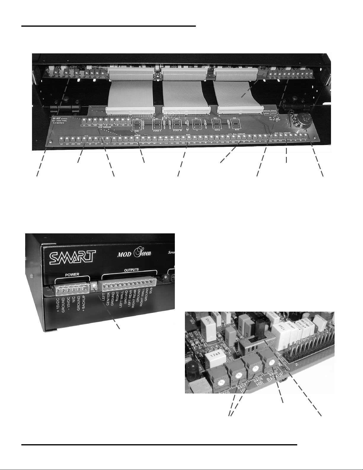
Preamp Configuration
The MOD 7 preamps can be configured through the use of shunts placed on header pins. The drawing below shows the
shunt locations and the purpose of each shunt. The PROJECTOR 2 input can be configured for use with a film projector or
for use as an audio input from a video source such as a DVD, LaserDisk, or VCR. When used as an audio for video input,
the left and right channels are processed through the Circle Surround matrix for multi-channel sound. The shunts for
SOLAR CELL and REVERSE SCAN apply to Projector 1 and Projector 2 individually. Each projector input can be configured differently.
Install both shunts for film projector.
(Factory setting)
Remove shunts for audio from video
source (DVD, LaserDisc, VCR).
Install shunts on pins marked PROJ 2
for film projector.
(Factory setting)
Install shunts on pins marked VIDEO
for audio from video source (DVD,
LaserDisc, VCR).
Install shunts on pins marked SOLAR
CELL for film projector with standard
exciter lamp/solar cell soundhead.
Install shunts on pins marked REV
SCAN for film projector with reverse
scan soundhead.
Install shunts on pins marked REV
SCAN (PROJ 2) for audio from video
source (DVD, LaserDisc, VCR).
(Factory setting)
(Factory setting)
Preamp Jumper Settings
Rear Left Corner of Main Board
6
Page 7

INSTALLATION & OPERATION
EX Power Up and Overhead Channel Configuration
The MOD 7 can be configured so that EX mode is either ON or OFF at power up. If you are not using the EX format,
then place this shunt in the OFF position.
The MOD 7 can be configured to deliver an overhead channel from digital soundtracks. If you are using a digital
player and have installed overhead speakers and amplifiers, then place this shunt in the OS position. Otherwise, leave
it in the CS position.
This shunt determines the power-up
setting for EX mode. With the shunt
in the OFF position, the MOD 7 will
power up with EX mode turned OFF.
(Factory setting)
This shunt determines whether the
RIGHT REAR output is used for a
rear surround (CS) channel
tory setting)
channel.
or an overhead (OS)
(Fac-
EX and Overhead Surround Jumper Settings
Right Rear Corner of Main Board
Noise Reduction Configuration
The MOD 7 can be configured to disable the Noise Reduction
circuitry. This is desirable if you are using the Projector 2 input for
an audio from video source (DVD, LaserDisk, VCR) since these
sources are NOT NR encoded.
The factory setting enables the Noise Reduction circuitry.
Install 4 shunts for noise reduction.
(Factory setting)
Remove shunts for audio from video
source (DVD, LaserDisc, VCR).
NR Jumper Settings
Left of Matrix Board
7
Page 8

MOD 7 STEREO PROCESSOR
MA TRIX CONFIGURA TION
Refer to the diagram on Page 9 for locations of switches
and LEDs mentioned in this section.
The DIP switches labeled CONFIGURATION are used for
setting the various operating modes. Normally, all these
switches are in the UP (off) position.
This configuration sets up the following modes:
Configuration Descriptions
SW1-1 causes the matrix to always be in Music mode.
This mode is optimized for non-matrix-encoded material
such as music CDs. Normally this mode is selected
automatically so the switch should be off.
SW1-2 selects between Split or Mono Surrounds.
SW1-3 selects the Soundspread option. This allows a
hard-panned left or right signal to also appear in the left
surround or right surround channels. This is normally not
used and is off in cinema applications.
SW1-4 selects between a phantom center channel for
Left/Right/Surround systems or a real center channel for
full Left/Center/Right/Surround systems.
SW1-5 OFF selects the Autobalance function which
automatically corrects for minor level imbalances in the
signals feeding the matrix. (SW1-5 ON defeats
Autobalance.)
Matrix LED Indicators
The STATUS LEDs indicate some of the operating conditions of the matrix. The RUN LED blinks once per second
if the microcontroller is operating properly. If it is not
blinking, then press the RESET pushbutton to restore
proper operation.
The CS LED is on for multiple stage channel mode (either
L/R or L/C/R). The FS led is on for Front/Surround
operation (no left and right channels). The film LED
indicates Cinema Mode and the MUSIC LED is for Music
mode. In the MOD 7, the matrix will switch modes
automatically as the format is changed from Music to any
Film format.
The SETUP LED comes on when SW1-8 (Pink Noise
Setup Switch) is on.
Overhead Channel Setup (matrix)
Place SW1-2 ON (down) when using the overhead
channel. This places the surround mode of the matrix in
mono which insures that all derived overhead material
appears in the overhead channel.
Pink Noise Setup
Pink noise is activated by setting SW1-8 ON (down) and
selecting the desired channels on SW2 as shown in the table
below. Be sure to turn OFF SW1-8 when done using pink
noise.
SW1-6 selects Front/Surround Mode or Multi-channel
Mode.
SW1-7 causes the matrix to always be in Cinema mode.
Useful when playing a LaserDisk or DVD through the
Music inputs. (Overrides SW1-1)
SW1-8 turns on Pink Noise
CONFIGURATION SWITCH FUNCTIONS
SW1 ON OFF
1 Force Music Mode Auto Cinema/Music Mode
2 Mono Surrounds Split Surrounds
3 Soundspread On Soundspread Off
4 Phantom Center Real Center
5 Autobalance Defeat Autobalance On
6 Front/Surround Mode Multi-Channel Mode
7 Force Cinema Mode Auto Cinema/Music Mode
8 Pink Noise Setup Mode Normal Mode
8
PINK NOISE SWITCH FUNCTIONS
SW2 ON - PINK NOISE OFF - NORMAL
1 Left Channel
2 Center Channel
3 Right Channel
4 Left Wall Surround Channel
5 Right Wall Surround Channel
6 Subwoofer Channel
Page 9
INSTALLATION & OPERATION
Time Delay Setup
The rotary switch is for setting the Surround Delay Time.
The switch is labeled as shown in this drawing:
POSITION DELAY (in mSec)
010
120
230
340
450
560
670
780
890
9 100
A 110
B 120
C 130
D 140
E 150
F 160
This table shows the
delay for each of the
switch settings. Set
the time delay as you
would for any stereo
processor
9
Page 10

MOD 7 STEREO PROCESSOR
INST ALLATION
Processor Placement
Before mounting the MOD 7 processor in the equipment rack or projector console, be sure to select a well ventilated area
that allows cool air to circulate around the individual components. Make sure that the processor is not immediately
adjacent to hum producing components such as power amplifiers with large transformers.
MOD 7 rear panel
Power Supply Connections
The PS-2 is a cool-running, universal switching power
supply that operates on 100-250 VAC (50-60Hz), needing
only a change in plug to operate in any country. It delivers
clean +15 and -15 DC voltages to the MOD 7 and has
enough extra power to run companion products. Mount
the PS-2 in any convenient place. Run the factory supplied
power supply wiring harness to the MOD VI processor.
Dress the wires for appearance and craftsmanship. The
wiring harness has a 6 position Phoenix pluggable terminal
strip that plugs into the leftmost plug labeled POWER on
the rear of the MOD 7.
WARNING: Do NOT plug a “live” power supply into the
back of the MOD 7 processor! Make sure that the power
supply is DISCONNECTED from the power mains before
connecting to the MOD 7. Failure to heed this warning can
cause fatal damage to internal components and void the
manufacturer’s warranty.
The wire codes for the main Power Supply are as follows
(from left to right on the back of the MOD 7):
Red : +15 VDC
Black : GROUND
White : -15 VDC
Backup Power Supply .
The backup power supply is a 12 VDC, 100mA supply that
is furnished only for countries with 120VAC mains. It
comes from the factory connected to the 6 position Phoenix
connector when shipped to 120VAC mains countries.
Customers in other countries will need to provide their
own 12 VDC, 100mA backup supply.
The wire codes for the Backup Power Supply are as follows
(from left to right on the back of the MOD 7):
Black w/ white stripe : +BACKUP
Black : GROUND
Remember to check all connections before applying power
to the system. A wire that is reversed could be very
destructive to the system.
Soundhead Connections
Solar Cell
Using three-conductor shielded cable, connect the wire
from the left solar cell (red) to the corresponding +LEFT1
input terminal of the MOD 7 SOUNDHEAD connector.
Connect the wire from the right solar cell (green) to the
+RIGHT1 input terminal. The common solar cell lead
(black) should be connected to both –LEFT1 and –RIGHT1,
and the shield of the cables should be connected to a
GROUND terminal. Be sure to cut off the shield at the
projector end so that a ground loop is not created. Only the
shields on the MOD 7 end of the cable should be grounded.
It is good practice to tape or shrink wrap the end of the
shielded cable at the sound head to prevent any stray
shield wires from grounding out to the sound head case.
Reverse Scan
If you are using a Reverse Scan system, use a two-conductor shielded cable to connect the -LEFT1 and +LEFT1
terminals on the MOD 7 to the corresponding terminals on
the Reverse Scan terminal block. Connect another twoconductor cable likewise from the -RIGHT1 and +RIGHT1
terminals to the corresponding terminals on the Reverse
Scan terminal block. The “neutral” wires (-LEFT1 and RIGHT1) should not be tied together.
10
Page 11

INSTALLATION & OPERATION
If you have a second projector, repeat the above steps
except hook your solar cell wires to the -RIGHT2,
+RIGHT2, -LEFT2 and +LEFT2 inputs.
DOUBLE CHECK your work to see that the solar cell leads
arrive at the proper terminals. A reversal of leads will
cause very strange results. You may hear the center
channel information through the surround speakers, the
surround through the stage, and the left channel out of
phase with the right. This is a common error, so verify
correct wiring before proceeding.
Connecting the MOD 7 to a Reverse Scan soundhead.
terminal must be tied to ground to activate Projector Two. It is
not a pulse-toggled input.
TWO PROJECTOR SYSTEMS - NO AUTOMATION:
Rig a single pole, single throw switch between the
CHANGEOVER terminal and a GROUND terminal.
When the switch is open, Projector 1 will be active, when it
is closed, Projector 2 will be active.
NOTE : Changeover between projectors is done electronically in the MOD 7. This necessitates that BOTH exciter
lamps be lit at the same time. No exciter light changeover is
provided in the unit. An exciter light changeover has at
least 3 dB more circuit noise than an electronic changeover
and is NOT recommended in high quality systems.
Non-Sync Music Connections
The non-sync music inputs for the MOD 7 are run through
the Circle Surround matrix to generate 5.1 channels of
auditorium music. Connect your stereo music source (CD
player, tape, etc.) to the MUSIC LEFT and MUSIC RIGHT
inputs on the back of the MOD 7.
Occasionally, a theater may use a monaural sound player
such as a background music cartridge player or satellite
music service that does not have stereo capabilities. In this
event, connecting a mono signal into both LEFT and RIGHT
MUSIC inputs will generate music in the center channel
only.
T wo Projector Systems
Connect the CHANGEOVER and GROUND terminals on
the MOD 7 AUTOMATION terminal strip to the booth
automation changeover relay terminals.
Projector changeover is accomplished by using only a
single pair of wires and either a manual switch or relay
contacts in the automation system. A relay closure in the
automation equipment will execute a changeover by
grounding the CHANGEOVER terminal. Run a twoconductor shielded cable to the “dry” contacts of the
automation projector changeover relay. On the other end,
connect one wire to the CHANGEOVER terminal on the
MOD 7. Ground the other wire to the nearest ground
terminal on the MOD 7. Connect the shield of the wire, on
the MOD 7 end, to a ground terminal. Cut off the shield on
the automation end. When the automation relay closes,
Projector Two of the MOD 7 will be “enabled,” and the first
pair of stereo preamplifiers (Projector One) will be “disabled.” Releasing the relay will cause the reverse action to
occur. In other words, Projector One is always ON until the
CHANGEOVER terminal is grounded. The CHANGEOVER
SMART recommends using a stereo distribution amplifier
such as the SMART DA226 to feed signals from one music
source to multiple sound processors.
Automation Connections
Connect the format pins on the AUTOMATION terminal
strip of the MOD 7 to the system’s corresponding automation relay terminals.
A momentary ground contact on one of the FORMAT
SELECT inputs on the rear of the MOD 7 will switch the
processor to any desired format, including music. The EX
format select terminal will toggle between EX ON and EX
OFF when pulsed to ground.
Note: The MOD 7 powers up in Non-Sync Music mode.
Muting Function
A convenient MUTE terminal in the AUTOMATION
section of the back panel allows all output channels of the
MOD 7 to be silenced whenever this terminal is grounded.
11
Page 12

MOD 7 STEREO PROCESSOR
Digital Player Connections
The MOD 7 has six inputs (Left, Center, Right, Left Surround, Right Surround and Sub) via a female DB25 connector marked DIGITAL INTERFACE. The DIGITAL IN-
TERFACE inputs accept any high level multi-channel
source. The audio signals are processed through the
equalizers and master volume circuit before they appear at
the main OUTPUTS. If EX mode is selected, then the Circle
Surround matrix processes the left surround and right
surround channels to produce the rear and overhead
channels.
SMART has interconnection cables available to connect the
popular digital player systems to the MOD 7. Simply plug
the appropriate DB25 connector to the MOD 7 DIGITAL
INTERFACE port and the other DB25 connectors to the
audio and control ports on the digital player.
If you desire to make your own cables, here is the pinout
for the DB25 connector.
Digital Interface DB25 Pinout
Pin 1 Left
Pin 3 Center
Pin 5 Right
Pin 6 Left Surround
Pin 7 Right Surround
Pin 8 SubWoofer
Pin 9 Mono
Pin 10 Music
Pin 11 Stereo A
Pin 12 Digital
Pin 13 Stereo SR
Pin 14-25 Ground
Another application for the digital input is for external sync
sources. Sound interlock from a 35-mm reproducer or a
single 16-mm projector may be fed into the DIGITAL
INTERFACE and selected with the front panel DIGITAL
format switch.
Monitor Interface
The MONITOR INTERFACE Port is a male DB25 connec-
tor to which a booth monitor’s processor inputs can be
connected. The pinout is as follows:
Pin 5 Right Rear/Overhead
Pin 7 Left Rear
Pin 12 +15 VDC
Pin 13 -15 VDC
Pin 15 Subwoofer
Pin 17 Right Wall
Pin 19 Left Wall
Pin 21 Right
Pin 23 Center
Pin 25 Left
Pins 2, 4, 6, 8,
10, 16, 18, 20,
22, & 24 Ground
Output Connections
The main OUTPUTS are labeled LEFT, CENTER, RIGHT,
LEFT WALL, LEFT REAR, RIGHT REAR, RIGHT WALL,
and SUB. Shielded cable should be run between these
terminals and the next piece of equipment in the sound
system (equalizer, amplifer, etc.). Convenient GROUND
terminals are provided near the outputs.
Output Wiring for non-EX applications
If you are not using the EX feature, then wire all surround
amplifiers to the LEFT WALL and RIGHT WALL termi-
nals. Do not use the LEFT REAR and RIGHT REAR
terminals.
Output Wiring for EX applications
If you are using the EX feature, then wire the left wall and
right wall amplifiers to the LEFT WALL and RIGHT
WALL terminals. Wire the left rear and right rear amplifiers to the LEFT REAR and RIGHT REAR terminals. Please
note: the CS/OS shunt must be in the CS position (see top
of Page 7 titled EX Power Up and Overhead Channel
Configuration)
Default Optical Selection
External digital decoders available on the market have a
function that instructs the processor to switch to an optical
format in the event that the digital decoder fails or loses
time code. When this happens, the digital decoder will
pulse the appropriate terminal (MONO, STEREO A,
STEREO SR, or MUSIC) to ground to alert the processor to
switch to the optical format. The information pertaining to
which format to default to is encoded in the digital
soundtracks on DTS prints. On Dolby Digital, the default is
SR.
12
Output Wiring for EX and Overhead Applications
If you are using the EX and overhead features, then wire
the left wall and right wall amplifiers to the LEFT WALL
and RIGHT WALL terminals. Wire the left rear and right
rear amplifiers to the LEFT REAR terminal. Wire the
overhead amplifier to the RIGHT REAR terminal. Please
note: the CS/OS shunt must be in the OS position (see top
of Page 7 titled EX Power Up and Overhead Channel
Configuration) Also SW1-2 on the matrix must be set to the
DOWN position.
Page 13

SYSTEM SETUP
INSTALLATION & OPERATION
Required Equipment
· sound pressure level meter
· real time analyzer (RTA) with a calibrated microphone
· dual trace oscilloscope
· multimeter
· a tuning wand
· S.M.P.T.E. Buzz Track Loop
· C.A.T. #97 Stereo Cell Alignment Film
· C.A.T. #69 Test Film
Before Calibrating
Turn on sound systems for 1/2 hour.
Turn off the EX feature.
Close the auditorium doors.
A-CHAIN CALIBRA TION
The A chain is usually considered to be the signal path
originating from the solar cell and continuing to the
processor’s master fader. This signal path includes the
preamp, noise reduction and matrix stages.
Preliminary
Clean soundhead optics, exciter lamp, optical lens and
solar cell before attempting a soundhead alignment.
Turn the master FADER all the way down to avoid
excessive noises in the auditorium for the next steps.
Soundhead Alignment
1 Play a S.M.P.T.E. Buzz Track loop.
2 Adjust the lateral film guide assembly, laser lens
assembly or exciter lamp assembly while monitoring the
preamp signals with the oscilloscope.
3 Adjust for minimum signal on the left and right channels.
Refer to specific instructions in the projector soundhead
manual. Minor variations in alignment procedure depend
on the individual mechanical design of the soundhead.
4. Play C.A.T. # 97 Stereo Cell Alignment Film.
5. Move laser lens or solar cell laterally and vertically
until you have achieved minimum crosstalk between
channels (see figure 6).
6. Repeat steps 1-5 until no further improvement can be
obtained.
Set exciter lamp voltage for at least 80% of rated voltage.
BMX 9 volt 4 amp – 7.2 volts
BXN 10 volt 5 amp – 8 volts
Most foreign 6.3 volt 4 amp – 5 volts
Make sure film/cell spacing is approximately 1 mm with
the slit image striking the top one-third of the solar cell.
Open the MOD VI front panel and connect Oscilloscope
and real time analyzer to the TP7 (left preamp) and TP8
(right preamp) test points.
TP7 and TP8 are located on the bottom side of the front
center of the MOD 7 main board between the J1 and J2
connectors. TPG (GROUND) is located to the left of J1, also
on the bottom side.
Turn Gain controls fully clockwise.
Turn Slit Loss controls fully counterclockwise.
The Preamp Gain controls are R1 and L1 for projector 1,
and R2 and L2 for projector 2. The Slit Loss controls are
LHF1 and RHF1 for projector 1, and LHF2 and RHF2 for
projector 2. Both sets of trimpots are located on the left
hand side of the front of the main circuit board.
Figure 6. Low crosstalk between channels
7. Play Pink Noise side of C.A.T. #69 Test Film.
8. Switch oscilloscope to X/Y Mode.
9. Adjust sound head optical lens azimuth for narrowest
diagonal trace (see figure 7).
13
Page 14

MOD 7 STEREO PROCESSOR
10 Observe the real time analyzer and focus the lens for
maximum high frequency output while maintaining the
best azimuth.
Figure 7. Pink noise in X/Y mode on the oscilloscope.
This is not easy, but it is one of the most critical adjustments affecting the overall system performance and is often
not done as well as it should be.
2. Adjust the left and right slit loss correction trimpots on
the PREAMP for optimum flat high frequency response.
Do not over adjust the slit loss correction in an effort to
obtain extended response. This will result in an undesirable frequency response peak. While adjusting the slit loss
correction, aim for as flat a high frequency response as
possible. If one of the preamp channels is slightly worse
that the other , then adjust the better responding preamp to
match the lesser. This will ensure that the matrix steering
in the MOD 7 will be as accurate as possible.
Optical Preamp Calibration
1. Run a Dolby C.A.T. #69 Test Film, Dolby tone side.
2. Locate the preamp calibration switch (SW1) and LEDs
(LED1 and LED2) on the left hand side of the front of the
main circuit board.
3. Push SW1 to the left. This causes the LEDs to indicate
the status of the Left channel preamp level.
Make sure you are changed over to the correct projector by
observing the CHANGEOVER terminal on the back of the
MOD 7. If the pin is open, the system is in projector 1
mode, if it is grounded, the system is in projector 2 mode.
4. Adjust Projector 1 left channel gain control (L1) until
both LEDs are lit.
11. Adjust the vertical and lateral alignment of the EXCITER LAMP for maximum output on both channels. This
is especially critical with a narrow slit optical lens because
there is a much smaller “window” for the light to pass
through.
12. Check the high frequency output on both channels and
make sure the response is the same on both channels.
With a narrow slit optical lens, the response should be flat
within ± 3 dB to about 12 kHz with NO slit loss correction.
If not, this MUST be corrected before proceeding with the
next steps. It is not permissible to use slit loss correction to
correct poor high frequency response caused by misalignment of the optical soundhead. An EXCITER LAMP out of
alignment, the barrel of the optical lens crooked, or oil in
the optical lens will all affect output and balance.
Slit Loss Correction
1. Run the Pink Noise side of C.A.T. #69 Test Film.
2. Observe the frequency response on your RTA which
should be still connected to the preamp testpoints.
This is a critical adjustment. You may not be able to get
both LED’s on simultaneously. Try to get as close as
possible.
5. Repeat steps 1-4 for the right channel gain control (R1),
and for projector 2 left and right channel gain control (L2
and R2).
Preamp Calibration LED’s
Left side potentiometers (Preamp, slit loss, hearing impaired, and
backup levels) and preamp calibration selector switch (SW1).
14
Page 15

You can verify that the LED meters are indicating correctly
by connecting an AC voltmeter to the LEFT PRE (TP7) and
RIGHT PRE (TP8) test points located on the bottom side of
the front of the main circuit board between connectors J1
and J2. Ground (TPG1) is located to the left of J1. You
should read between 300 to 325mVAC at these test points.
Bypass Setup
Bypass mode generates mono sound in the Center channel.
It is activated by pressing the red rocker switch to the
BYPASS position.
1. Run a film soundtrack.
INSTALLATION & OPERATION
Right side trimpots (Music, Digital, and Main output levels)
and Emergency Bypass switch
2. Listen to the CENTER channel on the booth monitor.
3. Switch from Normal to Backup.
The red Backup Switch (SW2) is mounted on the front right
of the main board, behind the front panel. Pushing the
switch to the right is BYPASS mode, to the left is NORMAL
mode.
4. Adjust the BYPASS level pot (on the left front side of the
main board) to achieve equal levels while switching from
Normal mode to Bypass mode.
B-CHAIN CALIBRA TION
The B Chain Calibration is generally considered to be the
signal path from the processor’s master fader to the speakers. This signal path includes the equalizers and output
stage. Before continuing with the B Chain Calibration,
check the wiring of all auditorium speakers to make sure
the phase is correct.
Preliminary
Special Note: If you will be installing an external digital
decoder, do so AFTER setting house levels. See the DIGITAL LEVEL SETTINGS at the end of the B CHAIN CALIBRATION section for more information.
1. Select STEREO A by pushing the appropriate button on
the front panel.
2. Set the FADER to the one o’ clock position.
Equalization and House Levels
The equalizers are normally shipped with the individual
trimpots set for a flat frequency response. The octave
equalizers used for the stage channels are capable of
cutting and boosting each frequency ±10 dB. The individual trimpots are single turn types, with the mid position
of each pot being flat (unity gain).
The MOD 7 has a built in Pink Noise Generator on the
Circle Surround Matrix Board. See pages 8 and 9 for a
description of the pink noise and time delay switches
Set the pink noise channel switches (SW2) on the Circle
Surround Matrix Card to the correct setting for the channel
you wish to equalize. Select the STEREO SR format.
Perform the channel equalization using the trimpots
located inside the front panel. The LO trimpot in each EQ
section mainly affects frequencies below 100Hz, and the HI
trimpot mainly affects frequencies above 10kHz.
After equalization of the each stage channel, adjust its
output level using the L, C, and R output trimpots on the
right front of the main circuit board so that 79 dBc spl is
measured in the auditorium for each channel.
If you are NOT using the EX feature, follow this procedure
for the Left Wall Surround and Right Wall Surround
channels. Adjust equalization as you normally would. Then
set the LW and RW level trimpots to obtain 76 dBc spl in
the auditorium for each channel.
If you ARE using the EX feature, follow this procedure for
the Left Wall Surround, Right Wall Surround, and EX
channels. Turn OFF the rear channel amplifier (or disconnect the rear speakers from the rear amplifier). Adjust
equalization as you normally would. Then set the LW and
RW level trimpots to obtain 76 dBc spl in the auditorium
for each channel.
15
Page 16

MOD 7 STEREO PROCESSOR
ISO Cinema Playback Standard states that octave bands
should be tuned for flat response to 2 kHz, with a 3 dB/
octave rolloff above 2 kHz.
The music is played through the matrix the same as a
soundtrack and provides 6 channel decoding from a
conventional 2-channel stereo source. This feature in the
MOD 7 presents a high impact playback in the auditorium
for pre-show entertainment. Although all 2 channel
commercial stereo recordings contain hidden “extra
channel” information due to multiple microphone recording or multi-track mixdown, you will really appreciate the
effect if you purchase CD’s that have been encoded in
“Circle Surround” with 6-channel source. There are many
new recordings available with the “Circle Surround” logo
on the CD case.
Now turn ON the rear channel amplifier and turn OFF the
left wall and right wall amplifier. Select left wall surround
AND right wall surround pink noise by pushing down
switches 4 and 5 on the pink noise dip switches. Equalize
the rear channel. Then adjust the REAR output level
trimpot for 76 dBc spl in the auditorium. Restore all amplifiers to the ON condition.
If you are using the OVERHEAD feature, select DIGITAL
format. Also select EX format. Select left wall surround
pink noise only. Adjust the ENV level trimpot (located on
the MOD 7 rear panel by the power connector-see picture
on page 17) to obtain 76 dBc spl in the auditorium.
Subwoofer Levels
With the SubWoofer Pink Noise channel on, adjust the sub
level trimpot (SUB) to the right on the front of the main
circuit board for 79 dBC spl from the subwoofer. The
installer may wish to adjust for another level, depending on
the amount of subwoofer desired.
Non-Sync Music Inputs
Select Music mode and turn on the music source that is
feeding the MOD 7.
Time Delay
Measure the distance in feet from the ideal seat (which is
usually 2/3 of the way back from the stage speakers,
centered side to side) to the stage speakers.
Measure the distance from the ideal seat to the nearest
surround speaker.
Subtract the two measurements.
Add 20 to this number to get the delay (in milliseconds)
required in the auditorium.
Set the rotary switch on the Circle Surround Matrix Card
(S1) to the nearest setting in milliseconds. See Page 9 for a
description of the time delay settings.
Digital Level Settings
The MOD 7 offers a digital level modifier trimpot (DIG)
that provides cut from the main FADER level when in
digital mode. In addition to externally trimming the
DIGITAL INPUT signals, the installer may use this trimpot
to fine tune the DIGITAL to Stereo-Optical sound level
matching.
Turn the left and right music level trimpots (LM and RM)
on the right front of the main board to obtain a normal
house level.
These trimpots are factory set and may not need adjustment. Adjust the trimpots so that right and left music are
set to the same level. A way to accomplish this is to play a
stereo music selection with a good vocal track and adjust
either the left or right music trimpots for minimum vocals
in the surround channel.
16
Make sure that all other B-chain calibration adjustments
have been made prior to adjusting the digital levels (see
special note in the PRELIMINARY section of the B CHAIN
CALIBRATION).
Make adjustments at the output of the external digital
decoder or interlock audio tape machine (see the digital
player manufacturer’s manual for details).
Use the DIG trimpot (located on the front right side of the
main circuit board) to fine-tune the digital level relative to
the Stereo-Optical level.
Page 17
INSTALLATION & OPERATION
Bypass Switch
A-Chain trimpots
Left EQ
Center EQ
Rear EQ
Front Panel Interior View
Overhead Channel Level
Right EQ
Left Wall EQ
B-Chain trimpots
The Hearing Impaired level and Backup Level adjustments
are located in the A-Chain trimpots section on the left hand
end of the main baord. The Preamp Calibration selector
switch is located just behind the Backup Level trimpot.
When the slide switch is to the left, the Left Channel
preamp is selected. When moved to the right, it selects the
Right Channel preamp.
Right Wall EQ
Fader Pot
The Overhead Level trimpot is located on the back panel by
the power connector. This will only need adjustment if you
are employing overhead speakers and amplifier.
Hearing Impaired Levels
Backup Level
Preamp Calibration Channel
Selector Slide Switch
17
Page 18

MOD 7 STEREO PROCESSOR
OPERA TING INSTRUCTIONS
The MOD 7 system is one of the easiest systems to operate.
The Managaer/Operator of the sound booth should review
the operation instructions to assure that emergency functions are also understood in the unlikely event of an
equipment failure.
TURNING ON THE SYSTEM
The sound engineer who installed the sound system has
provided a way to apply power to the system through a
master power switch or circuit breaker. Also, several of the
individal components in the equipment rack have their
own power switches. Become familiar with all switches or
breakers that control power to the sound equipment.
The MOD 7 is equipped with a power up muting circuit
that allows time for the low level circuits to stabilize before
enabling the processor outputs. This circuit prevents a
“turn-on thump” from being passed to the auditorium
speakers. However, since most amplifiers are not equipped
with a comparable muting circut for the power down
sequence, it is recommended that the amplifiers be turned
off before the processor to avoid a “turn-off thump” in the
auditorium.
MUSIC SELECTION
It is likely that the sound system will be turned on before
the arrival of the first audience of the day. The MOD 7
powers up in Music mode. If the music player (CD player
or tape machine) is running, music will be heard in the
auditorium and on the booth monitor. Music may also be
selected by pressing the front panel MUSIC button.
PROGRAM SELECTION
The automation should be set to select the proper formats
when needed. However, any format may be overriden by
simply pushing one of the Format buttons located on the
front of the MOD 7.
MUSIC LEVEL CONTROL
The music level should have been preset by the installer of
the sound system. However, if any change in music level is
desired then the LM (Left) and RM (Right) music level
controls can be turned to change the overall volume level.
These trimpots are located behind the front panel on the
right front of the main circuit board. The front panel is
mounted on hinges and latched by magnets, so a light tug
on the top of the panel should open it for access.
BYPASS SWITCH
The MOD 7 contains an emergency bypass system that will
keep the sound on the screen in the event of a failure of the
processor. This special circuitry is activated by the BYPASS
switch, which is located behind the front panel on the front
right of the main circuit board. The switch is bright red, and
switching it to the right puts the system in BYPASS, to the
left is NORMAL mode. During BYPASS, sound is produced only through the Center channel.
BYPASS uses the same preamp circuitry as normal operation. The power is supplied simultaneously by the main
supply and a small backup power pack. In the unlikely
event of preamp circuitry failure, the backup system may
not function. If this happens, please contact your service
technician or call the SMART factory.
EX Format
The EX function (activated by the button on the front panel)
applies special processing to the Left Surround and Right
Surround channels in DIGITAL format. This process
extracts the Center Surround (REAR) channel. If your
system is equipped for EX playback, SMART recommends
keeping EX turned on all the time.
If your cinema is NOT equipped to play in EX format, then
make sure to keep the EX format turned off.
VOLUME LEVEL
The front panel FADER control is used to set the system
level for any format. The system was calibrated with the
FADER at the one o’clock position, which is where most
prints will play at a normal level.
18
 Loading...