

Page 1
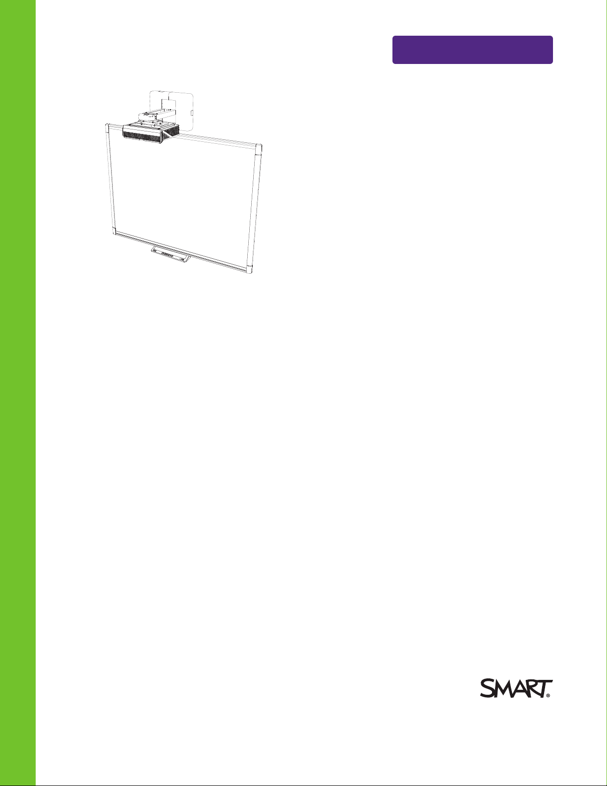
SMARTBoard® M600ix3
Help us make t hi s document better
smar ttech.com/docfeedback/170910
interactive whiteboard systems
CONFIGURATION AND USER’S GUIDE
FOR MODELS M680ix3 AND M685ix3
Page 2

FCC war nin g
This e quipment has b ee n tes ted and found to comply withthe li mits for a Class A dig ital d evi ce, p ursuant to Part 15 o f the FCC Rules . Thes e li mits are desi gned to
pro vide reaso nable p rotectio n against harmful interfer ence when the eq uipment is oper ated in a commercial e nvironment. T his eq uipment g ener ates, uses and
can rad iate radio frequency ene rgy and, i f not installed and used in accord ance with the manufacturer’s instructions, may cause harmful interfer ence to r adio
communications. Oper ation o f this e quipment in a r esi dential are a is likely to cause harmful i nterfere nce in which case the user will be require d to co rre ct the
interfere nce at his own exp ense .
Trad emark no tic e
SMARTBoard , SMARTNo tebo ok, SMARTMee tingPro, DViT, smarttech, the S MART lo go and all SMART tagline s are trademarks o r re gi stere d trade marks of
SMARTTe chnologie sU LC in the U.S . and/or other countries. Micros oft, Windows and InternetExpl ore r are either re gis tere d trade marks or trademarks o f
Microso ft Cor por ation i n the U.S . and/or o ther countries. All other third -party p ro duct and co mpany names may be trademarks of their r esp ective owners.
Copyri gh t n ot ice
© 2 013–201 5 SMARTTe chnologi esU LC. All rights r ese rve d. No p art of this publicatio n may b e r ep rod uced, transmitted, transcri be d, sto red in a retri eval s ystem
or translated into any language i n any form by any means w ithout the p rio r wr itten co nsent o f S MARTTechnolog ie sULC. Information in this manual is subject to
change without notice and d oes not re pre se nt a commitment o n the part o f S MART.
This p rod uct and/or use thereo f cove red by one o r more of the foll owing U .S. p atents: s marttech.com/patents.
05/2015
smar ttech.com/kb/170910
Page 3

Important information
Before you install and use the SMARTBoard® interactive whiteboard system, read and understand
the safety warnings and precautions in this user’s guide and the included important information
document. These safety warnings and precautions describe the safe and correct operation of the
interactive whiteboard system and its accessories, helping you prevent injuries and equipment
damage. Ensure that the interactive whiteboard system is always used correctly.
In this document, “interactive whiteboard system” refers to the following:
l SMARTBoard M685 series interactive whiteboard
l SMARTU100 or SMARTU100w projector
l Accessories and optional equipment
The projector included with the system is designed to work only with certain SMARTBoard
interactive whiteboard models. Contact your authorized SMART reseller (smarttech.com/where) for
more information.
Safety warnings, cautions and important information
Installation
WARNI NG
l Failure to follow the installation instructions shipped with the SMART product could result in
injury and damage to the product.
l To reduce the risk of fire or electric shock, do not expose the SMART product to rain or
moisture.
l Two people are required to mount your SMART product because it may be too heavy for
one person to safely maneuver.
When you lift the interactive whiteboard, you and your assistant should stand on either side
of the screen, supporting its weight at the bottom while balancing the top with your other
hand.
i smar ttech.com/kb/170910
Page 4
IMP ORTAN T INFORMATI ON
l When mounting the projector boom on a framed or hollow wall, attach the mounting bracket
to a stud to safely support the projector’s weight. If you use only drywall anchors, the drywall
can fail, resulting in possible injury and damage to the product which may not be covered
by the warranty.
l Do not leave cables on the floor where they can be a tripping hazard. If you must run a cable
over the floor, lay it in a flat, straight line and secure it to the floor with tape or a cable
management strip of a contrasting color. Handle cables carefully and avoid excessive
bending.
CAUTION
l Do not operate this unit immediately after moving it from a cold location to a warm location.
When the unit is exposed to such a change in temperature, moisture can condense on the
lens and crucial internal parts. Allow the system to reach room temperature before
operation to prevent possible damage to the unit.
l Do not place the unit in hot locations, such as near heating equipment. Doing so could cause
a malfunction and shorten the life of the projector.
l Avoid setting up and using the SMART product in an area with excessive levels of dust,
humidity and smoke.
l Do not place your SMART product in direct sunlight or near any appliance that generates a
strong magnetic field.
l You must connect the USB cable that came with your SMARTBoard interactive whiteboard
to a computer that has a USB compliant interface and that bears the USB logo. In addition,
the USB source computer must be compliant with CSA/UL/EN 60950 and bear the CE mark
and CSA and/or UL Mark(s) for CSA/UL 60950. This is for operating safety and to avoid
damage to the SMARTBoard interactive whiteboard.
IMPORTANT
l Use the
SMARTBoard M600ix3 interactive whiteboa rd system installation guide
(smarttech.com/kb/170886) to install the interactive whiteboard and projector.
l Make sure an electrical socket is near the SMART product and remains easily accessible
during use.
l Using the SMART product near a TV or radio could cause interference to the images or
sound. If this happens, move the TV or radio away from the projector.
ii smar ttech.com/kb/170910
Page 5
IMP ORTAN T INFORMATI ON
Operation
WARNI NG
l If you are using an external audio system, use only the power supply included with that
product. Using the wrong power supply might create a safety hazard or damage the
equipment. If in doubt, refer to the specification sheet for your product to verify the power
supply type.
l Do not climb (or allow children to climb) on a wall- or stand-mounted SMARTBoard
interactive whiteboard.
Do not climb on, hang from or suspend objects from the projector boom.
Climbing on the interactive whiteboard or projector boom could result in injury or
product damage.
l Refer to the safety warnings and precautions published by the projector
manufacturer. Do not stare (or allow children to stare) directly into the projector’s beam of
light.
l Do not touch (or allow children to touch) your projector because it can become extremely
hot during normal operation.
l Do not stand (or allow children to stand) on a chair to touch the surface of the SMARTBoard
product. Instead, safely fix the product at the appropriate height on a wall or use a SMART
height-adjustable floor stand.
l To prevent injury or product and property damage, use only the mounting hardware
supplied with the SMARTBoard M600 series interactive whiteboard when you install the
product on drywall. The mounting hardware provided with other interactive whiteboards
may not be strong enough to support the weight of SMARTBoard M600 series interactive
whiteboards.
CAUTION
l Do not block the projector’s ventilation slots and openings.
IMPORTANT
l Keep the remote control in a safe place because there is no other way to access menu
options.
l Disconnect the product from its power source when it’s not used for a long period.
iii smar ttech.com/kb/170910
Page 6

IMP ORTAN T INFORMATI ON
Other precautions
If you’re using a SMARTproduct other than a SMARTBoard interactive whiteboard system, refer to
the product’s installation manual for relevant warnings and maintenance instructions.
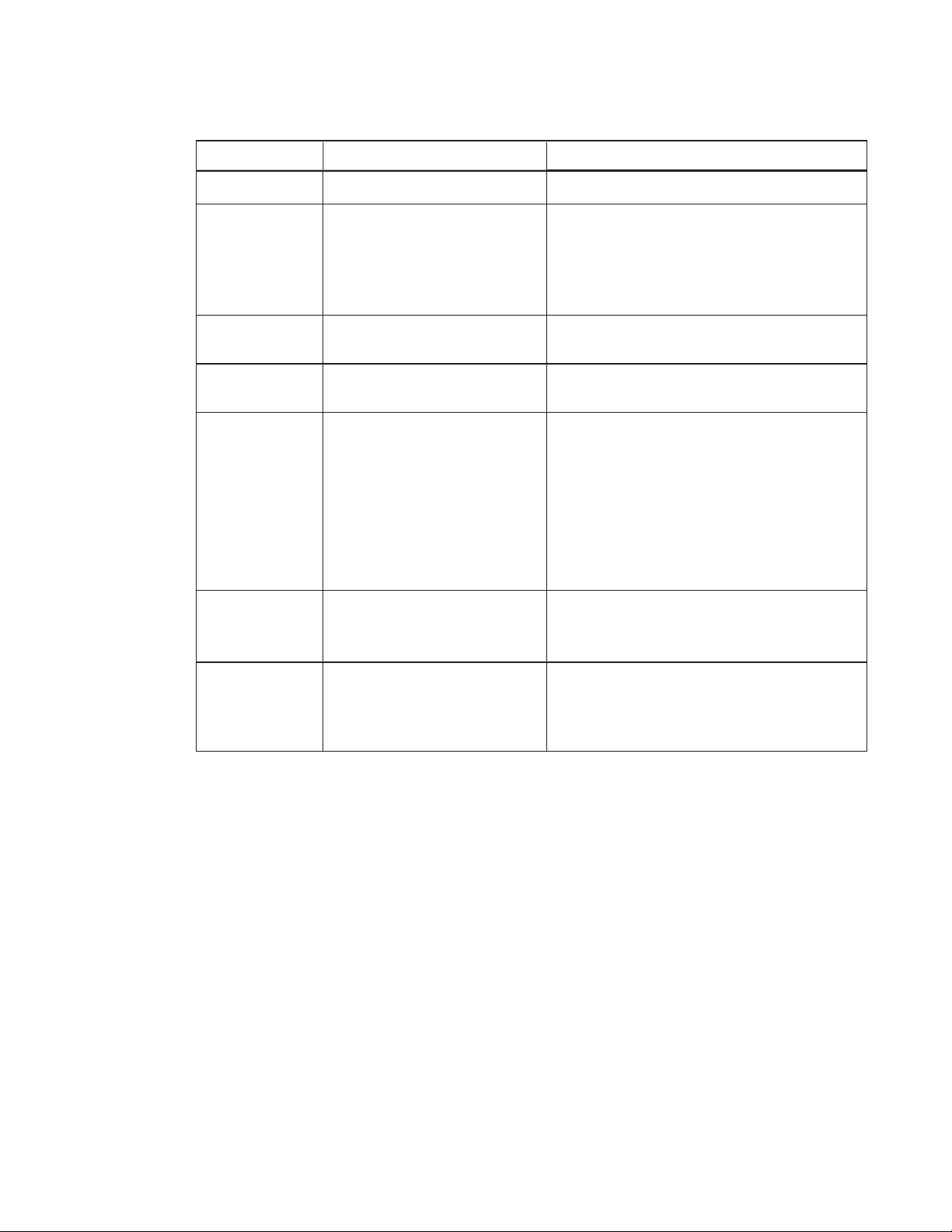
Environmental requirements
Before you install the SMARTBoard interactive whiteboard system, review the following
environmental requirements.
Environment al
Parameter
requirement
Operating temperature
Operating temperature
(projector)
41°F to 95°F (5°C to 35°C) from 0' to 6000' (0 m to 1800 m)
l
41°F to 86°F (5°C to 30°C) from 6000' to 9800' (1800 m to 3000 m)
l
Standard speed: 41°F to 95°F (5°C to 35°C) from 0' to 6000' (0 m to
l
1800 m)
High speed: 41°F to 86°F (5°C to 30°C) from 6000' to 6800' (1800 m
l
to 2100 m)
Storage temperature -4°F to 122°F (-20°C to 50°C)
Humidity
Up to 85% storage relative humidity, non-condensing
l
Up to 85% operating relative humidity, non-condensing
Water and fluid
resistance
Intended for indoor use only. Doesn’t meet any salt-spray or water
l
ingress requirements.
Don’t pour or spray liquids directly onto your interactive whiteboard,
l
the projector or any of its sub-components.
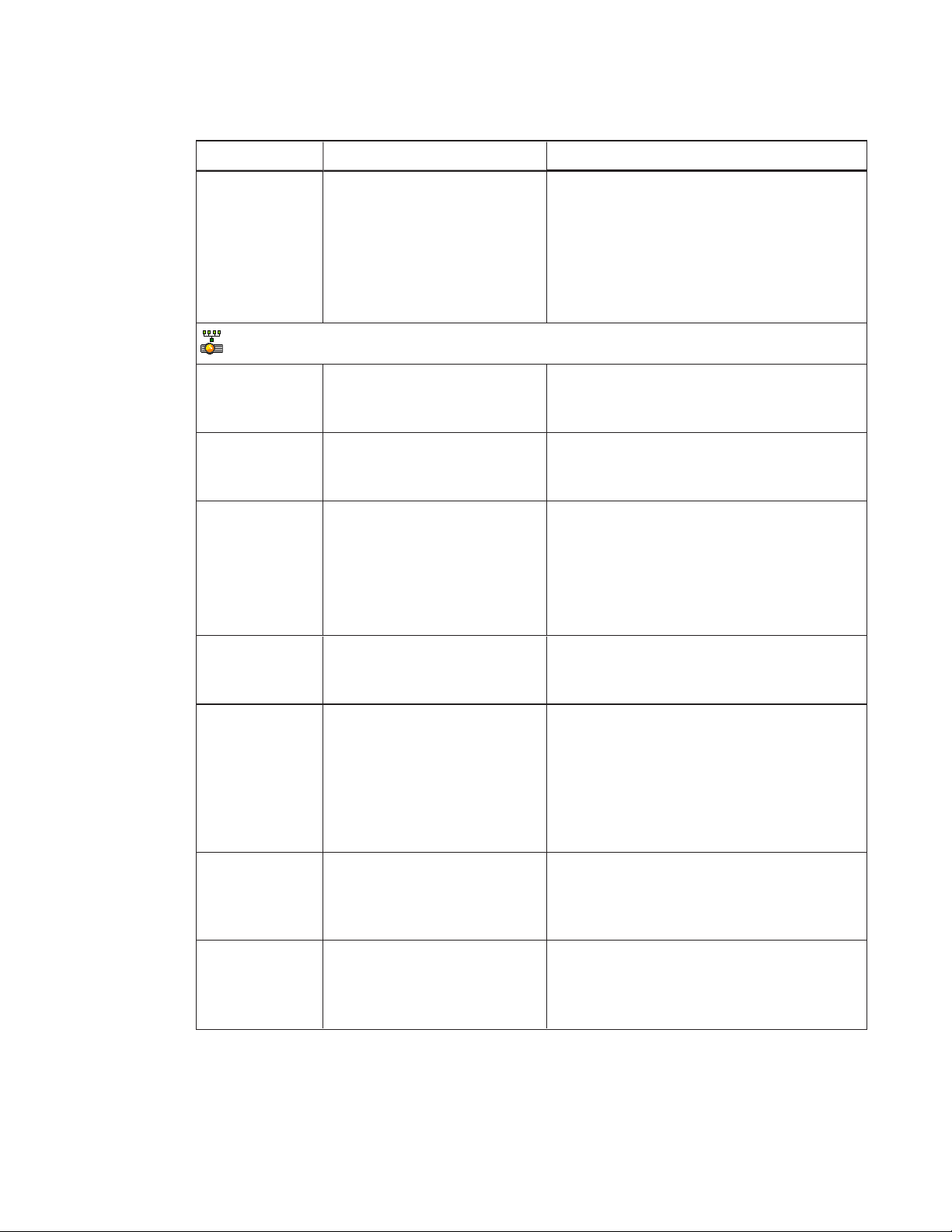
Dust Intended for use in office and classroom environments. Not for
industrial use where heavy dust and pollutants can cause
malfunctions or impaired operation. Periodic cleaning is required in
areas with heavier dust. See
Cleaning the projector
on page28 for
information on cleaning the projector.
Electrostatic discharge
(ESD)
EN61000-4-2 severity level 4 for direct and indirect ESD
l
No malfunction or damage up to 8kV (both polarities) with a
l
330ohm, 150 pF probe (air discharge)
Unmated connectors meet no malfunction or damage up to 4kV
l
(both polarities) for direct (contact) discharge
Cables All SMARTBoard interactive whiteboard system cables should be
shielded to prevent potential accidents and degraded video and
audio quality.
Conducted and
EN55022/CISPR 22, Class A
radiated emissions
iv smarttech.com/kb/170910
Page 7

Contents
Important informat ion i
Safety warnings, cautions and important information i
Environmental requirements iv
Chapter 1: About th e int eractive whiteboard system 1
SMARTBoard interactive whiteboard system features 2
Included accessories 4
Chapter 2: Inst alling t he int eractive whit eboard system 5
Choosing a location 5
Choosing a height 6
Securing the projector to the boom 6
Routing the cables 7
Installing SMART software 7
Chapter 3: Using the int eractive whiteboard system 9
Using the projector 9
Using the interactive whiteboard 25
Chapter 4: Maint aining the int eractive whiteboard system 27
Maintaining the interactive whiteboard 27
Cleaning the projector 28
Focusing and adjusting the projector image 29
Replacing the projector lamp 29
Chapter 5: Troubleshooting the interact ive whit eboard system 37
Before you start 38
Determining the interactive whiteboard system’s status 39
Resolving interactive whiteboard issues 42
Resolving projector errors 42
Resolving image issues 43
Resolving audio issues 47
Resolving network communication issues 48
Accessing the service menu 48
Transporting the interactive whiteboard system 49
Appendix A: R emot ely managing t he system through a network interface 51
Web page management 51
Simple Network Management Protocol (SNMP) 59
v smarttech.com/kb/170910
Page 8

CONTENTS
Appendix B: Remotely managing the system t hrough an RS-232 serial int erface 61
Serial interface settings 62
Projector programming commands 63
Appendix C: Integrating ot her devices 89
Video format 89
Connecting peripheral sources and outputs 95
Appendix D: Remote control code definit ions 97
Appendix E: Hardware environmental compliance 99
Waste Electrical and Electronic Equipment and Battery regulations (WEEE and
BatteryDirectives) 99
Batteries 99
Mercury 99
More information 99
Index 101
vi smarttech.com/kb/170910
Page 9

Chapter 1
system
SMARTBoard interactive whiteboard system features 2
SMARTBoard M600 series interactive whiteboard 2
SMARTU100 or SMARTU100w projector 3
Included accessories 4
Remote control 4
Pens 4
Optional accessories 4
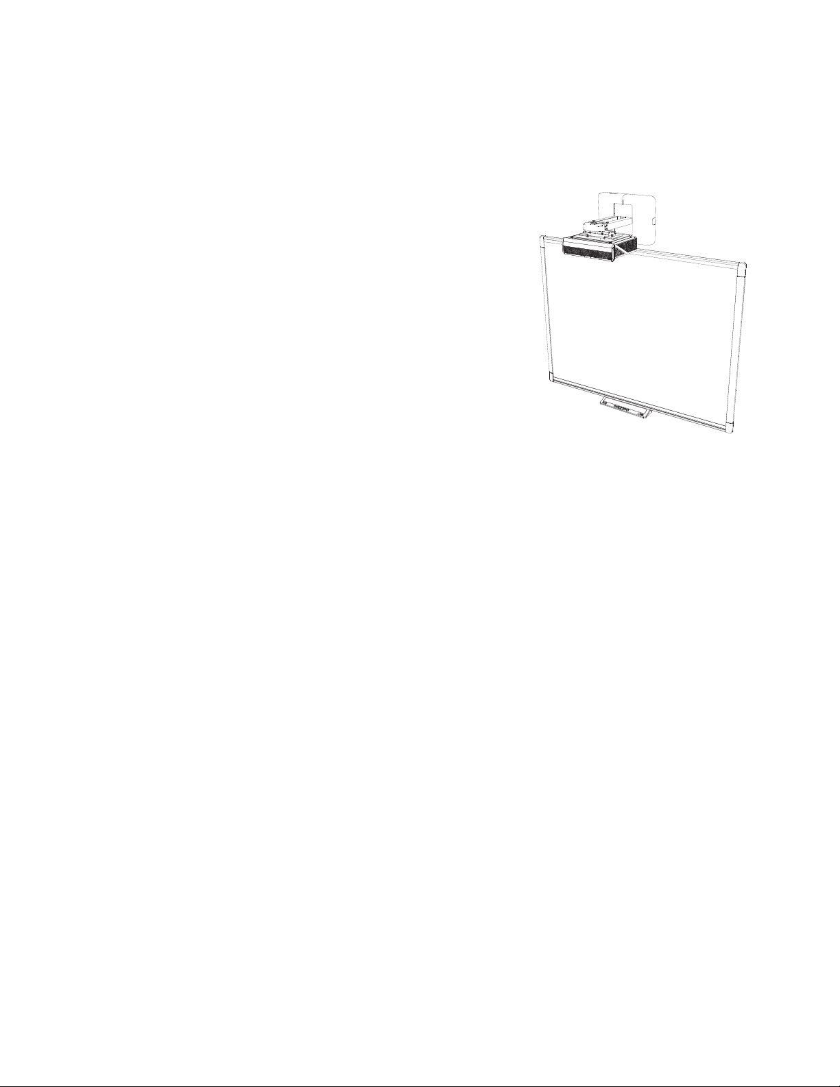
The SMARTBoard interactive whiteboard system combines the following components:
l SMARTBoard M600 series interactive whiteboard
l Wall-mounted, short-throw SMARTU100 or SMARTU100w projector
l Accessories and optional equipment
This chapter describes the features of the interactive whiteboard and provides information about
product parts and accessories.
1 smar ttech.com/kb/170910
Page 10
CHAPTER 1
ABOUT THE I NTERACTIVE WHITEBOARD SYSTEM
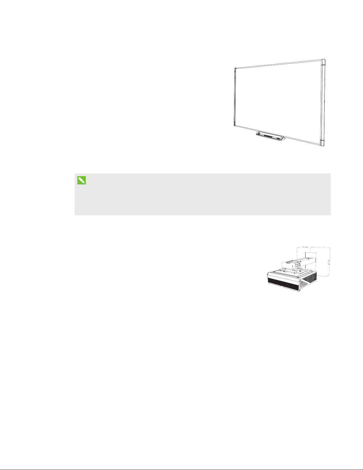
SMARTBoard interactive whiteboard system
features
Your SMARTBoard interactive whiteboard system
uses the short-throw, high-offset SMARTU100 or
SMARTU100w projector. When the projector
displays an image from your computer on the touch-
sensitive interactive whiteboard, you can do
everything that you can do at your computer—open
and close applications, scroll through files,
conference with others, create new documents or
edit existing ones, visit websites, play video clips and
more—by touching the screen. You can use an array
of gestures within applications.
This projector also supports video and audio
connections from a variety of devices, including
DVD/Blu-ray™ players, VCRs, document cameras and digital cameras, and can project media from
these sources onto the interactive screen.
When you use SMART software with your SMARTBoard interactive whiteboard system, you can
write or draw over the projected computer image in digital ink using a pen tray pen or your finger,
and then save these notes to a .notebook file or directly into any Ink Aware application.
SMARTBoard M600 series interactive whiteboard
Your SMARTBoard M600 series interactive whiteboard, featuring SMART’s proprietary DViT®
(DigitalVisionTouch) technology, is the most intuitive touch-sensitive front projection interactive
whiteboard in the world.
The SMARTBoard M600 series interactive whiteboard performs best with the SMARTU100
projector because of its exceptional color performance, aspect ratio, input response and short-
throw image distance.
2 smar ttech.com/kb/170910
Page 11
CHAPTER 1
ABOUT THE I NTERACTIVE WHITEBOARD SYSTEM
Other features of your interactive whiteboard include
the following:
l Pen tray buttons that activate the pens’ colors
and the on-screen keyboard, as well as right-
click and Orientation functions
l A durable hard-coated surface that is optimized
for projection and is easily cleaned
For more information about your SMARTBoard
interactive whiteboard, see the
SMARTBoard M600
series interactive whiteboa rd user’s guide
(smarttech.com/kb/170410).
NOTE
Because of its wide-screen format, the SMARTU100w projector is compatible only with
SMARTBoard M685 interactive whiteboards, and not with SMARTBoard M680 interactive
whiteboards.
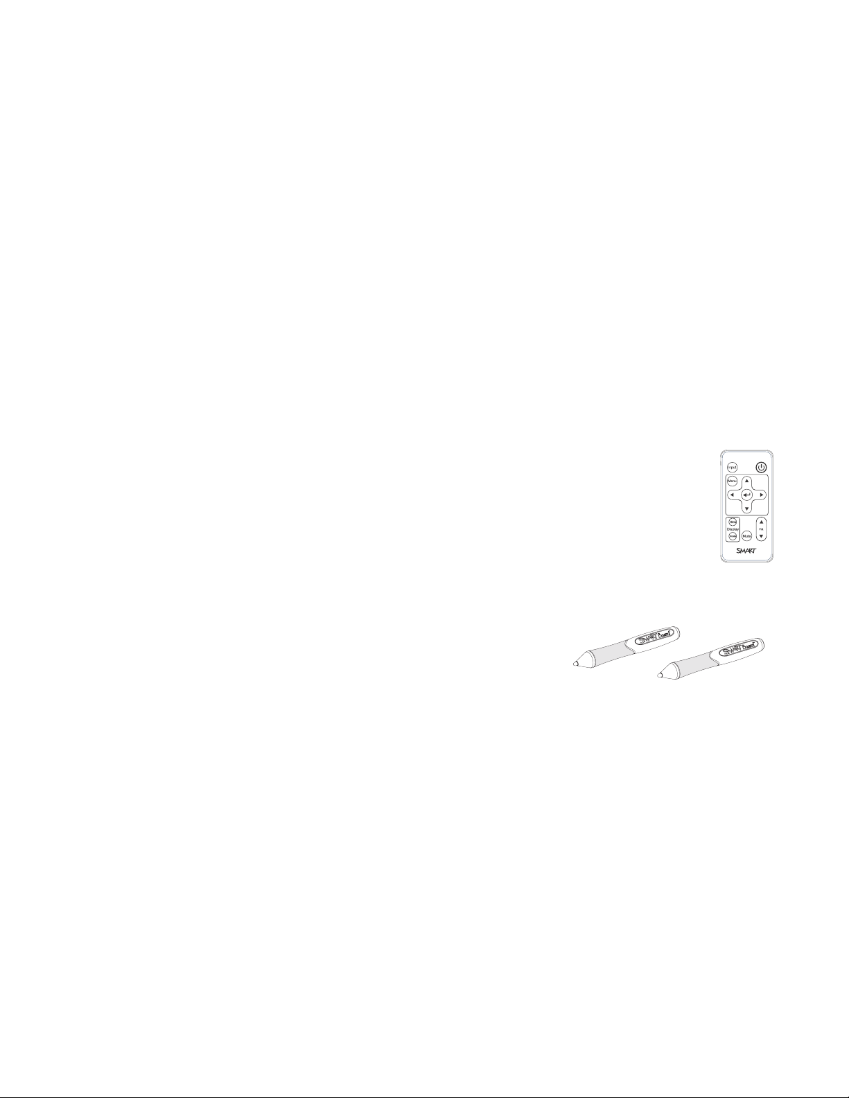
SMARTU100 or SMARTU100w projector
The SMARTU100 or SMARTU100w projector system includes a short-
throw projector for use with SMARTBoard interactive whiteboards
and a sturdy support system suitable for many different environments.
Other features of the projector system include the following:
l A wall-mounted, high-offset projector engine that uses DLP®
technology by TexasInstruments™, providing BrilliantColor™
performance and Gamma 2.2 correction with SMART
Presentation, Bright Room, Dark Room, sRGB and User modes
l Philips® ImageCare™ lamp control technology extends lamp life
l PAL, PAL-N, PAL-M, SECAM, NTSC and NTSC 4.43 video system compatibility
l HDMI, Composite,and VESA® RGB video inputs
l UXGA, SXGA+, SXGA, WXGA, XGA, SVGA, VGA video format compatibility
l Native 1024 × 768 resolution (SMARTU100 projector)
OR
Native 1280 × 800 resolution (SMARTU100w projector in 16:10 aspect ratio mode)
l Remote management via a serial RS-232 interface, web page or SNMP
3 smarttech.com/kb/170910
Page 12
CHAPTER 1
ABOUT THE I NTERACTIVE WHITEBOARD SYSTEM
l An alert broadcast feature that enables administrators to send notification messages to
network-connected projector systems for immediate on-screen display
l Protected cable routing through a cable cover that limits tampering and clutter
l A secure mounting and installation system that includes the following:
o
An optional projector padlock ring to prevent removal of the projector from the boom
o
Accessory mounting hardware for solid masonry or framed wall installations kit (Part
Number 1007416)
o
Templates and instructions for positioning the system safely
Included accessories
The following accessories are included with the interactive whiteboard system.
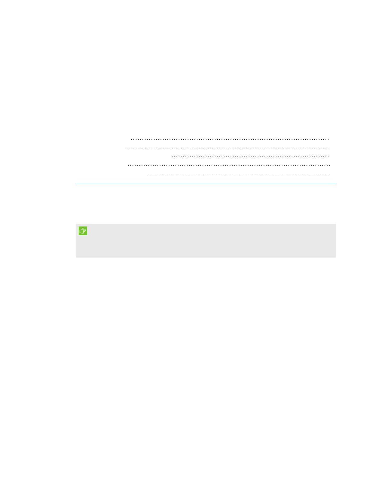
Remote control
The remote control enables you to control the system and set up your projector. Use
the remote control to access menu options, system information and input selection
options.
Pens
There are two pens included with the interactive whiteboard.
Pick up a pen and press one of the four color buttons on the
pen tray (black, red, green or blue) to select the color of digital
ink you write on the interactive whiteboard.
Optional accessories
You can add a variety of accessories to your interactive whiteboard to best meet your specific
needs. Purchase these items from your authorized SMART reseller (smarttech.com/where).
For more information on accessories, go to smarttech.com/accessories.
4 smarttech.com/kb/170910
Page 13
Chapter 2
system
Choosing a location 5
Choosing a height 6
Securing the projector to the boom 6
Routing the cables 7
Installing SMART software 7
Consult the SMARTBoard interactive whiteboard system installation document included with your
product for instructions on how to install and secure the system.
IMPORTANT
Use the
(smarttech.com/kb/170886) to install the interactive whiteboard and projector.
This chapter provides additional considerations and details for installing the interactive whiteboard
system.
SMARTBoard M600ix3 interactive whiteboa rd system installation guide
Choosing a location
Choose a location for the interactive whiteboard system that’s far from bright light sources, such as
windows and strong overhead lighting. IR lighting can cause issues with the performance of the
cameras and can lead to unintentional or missed touches.
Select a wall with a flat, regular surface and sufficient clearance to accommodate the interactive
whiteboard system. Install the projector and your interactive whiteboard on the same flat surface.
For best presentation alignment, mount the interactive whiteboard system in a location that’s
central to your audience’s viewing direction.
For mobile or adjustable installation options, contact your authorized SMART reseller.
5 smar ttech.com/kb/170910
Page 14
CHAPTER 2
INSTALLING THE INTERACTIVE WHITEBOARD SYSTEM
WARNI NG
Refer to the interactive whiteboard system’s specifications (available at smarttech.com/support)
for its weight. Check local building codes to ensure that the wall can support this weight, and use
appropriate mounting hardware for the wall type.
Choosing a height
SMART includes a mounting template with each interactive whiteboard system. If you lose this
template, contact your authorized SMART reseller. Using this template ensures that you can do the
following:
l Mount the projector at a safe height for head space clearance, while maintaining enough
space for airflow and installation access above the unit.
l Position the projector at the correct height above the interactive whiteboard to align the
projected image with the touch screen.
Dimensions on the template recommend a distance from the floor suitable for adults of average
height. Consider the general height of your user community when you choose a location for the
interactive whiteboard.
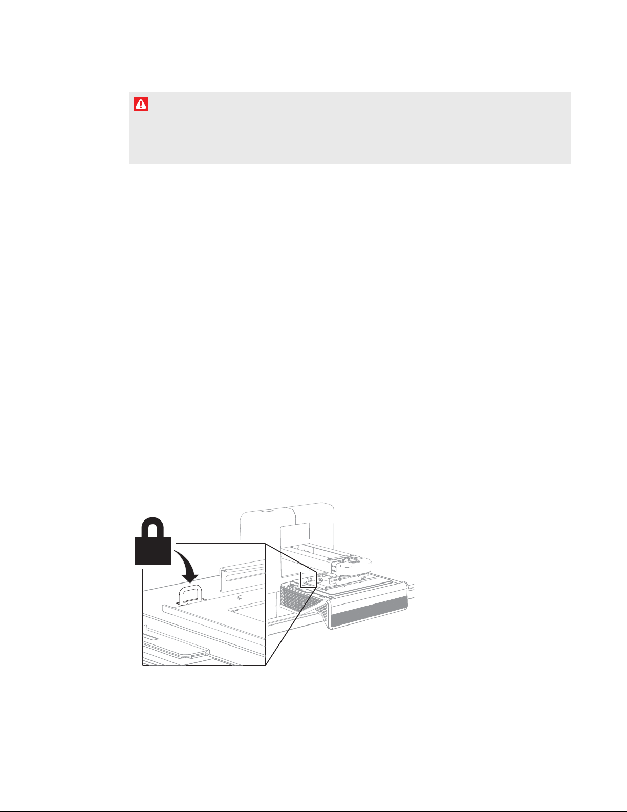
Securing the projector to the boom
The top surface of the projector features a secure metal loop that can accommodate a cable
you’ve secured to the projector boom.
6 smar ttech.com/kb/170910
Page 15
CHAPTER 2
INSTALLING THE INTERACTIVE WHITEBOARD SYSTEM
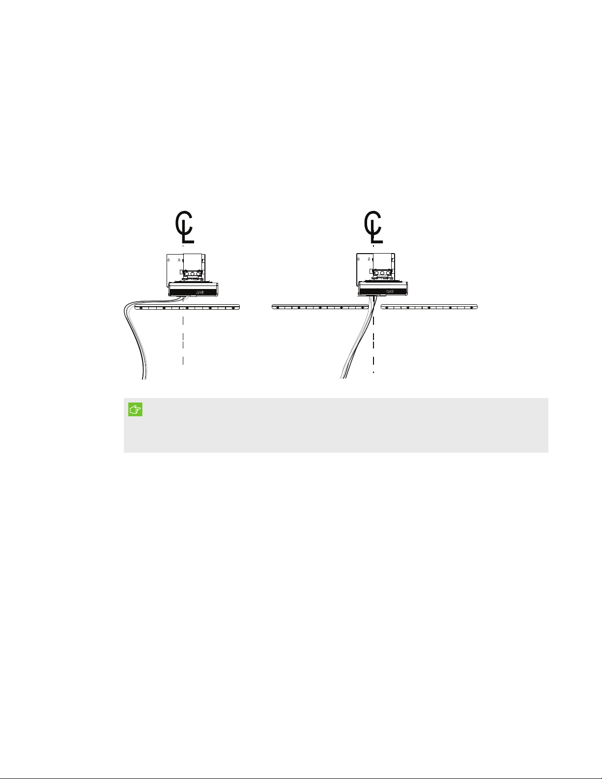
Routing the cables
If the interactive whiteboard uses one mounting bracket, make sure that all projector cables pass
along the top of the bracket and then down the side of the interactive whiteboard.
If the interactive whiteboard uses two mounting brackets, make sure that all projector cables pass
between the brackets. Space the wall-mounting brackets 4" (10.2 cm) apart to provide full support
for the interactive whiteboard’s weight.
IMPORTANT
Do not connect the power cable to a power outlet until you have connected all the cables to the
projector and interactive whiteboard.
Installing SMART software
To access all the features of the interactive whiteboard system, install SMARTsoftware, such as
SMARTNotebook® collaborative learning software, on the connected computer.
Download SMARTsoftware from smarttech.com/software. These web pages list the minimum
hardware requirements for each software version. If SMART software is already installed on your
computer, take this opportunity to upgrade the software to ensure compatibility.
7 sm arttech.com/kb/170910
Page 16

Page 17

Chapter 3
system
Using the projector 9
Using the remote control 9
Replacing the remote control battery 10
Using the remote control buttons 11
Adjusting projector settings 12
Focusing the image 22
Adjusting the image 23
Projector connection diagram 23
Using the interactive whiteboard 25
This chapter describes the basic operation of the interactive whiteboard system and explains how
to set up the remote control, retrieve system information, access the projector’s image adjustment
options and integrate the interactive whiteboard system with peripheral devices.
Using the projector
Using the remote control
The projector remote control enables you to access on-screen projector menus and change
projector settings.
9 smar ttech.com/kb/170910
Page 18
CHAPTER 3
USING THE I NTERACTIVE WHITEBOARD SYSTEM
Replacing the remot e cont rol bat t ery
Follow this procedure to replace the remote control battery.
WARNI NG
l Reduce the risk associated with a leaking battery in the projector’s remote control by
following these practices:
o
Use only the specified CR2025 coin-cell battery.
o
Remove the battery when the remote control is unused for an extended period.
o
Do not heat, disassemble, short or recharge the battery, or expose it to fire or high
temperatures.
o
Avoid eye and skin contact with the battery if it has a leak.
l Dispose of the exhausted battery and product components in accordance with applicable
regulations.
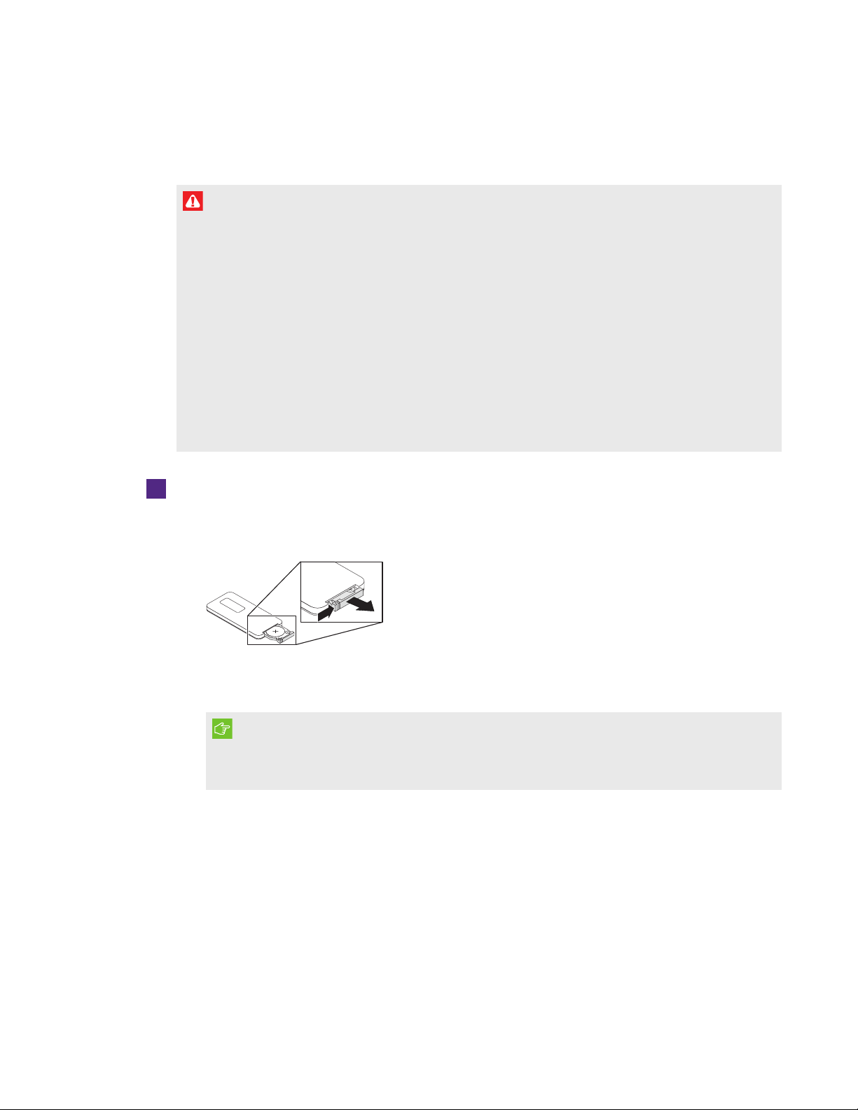
To replace the remote control batt ery
1. Hold down the side release on the leftside of the battery holder and pull the battery holder
completely out of the remote control.
2. Remove the old battery from the battery holder and replace it with a CR2025 coin-cell
battery.
IMPORTANT
Align the battery’s positive (+) and negative (–) terminals with the correct signs on the
battery holder.
3. Insert the battery holder into the remote control.
10 smar ttech.com/kb/170910
Page 19
CHAPTER 3
USING THE I NTERACTIVE WHITEBOARD SYSTEM
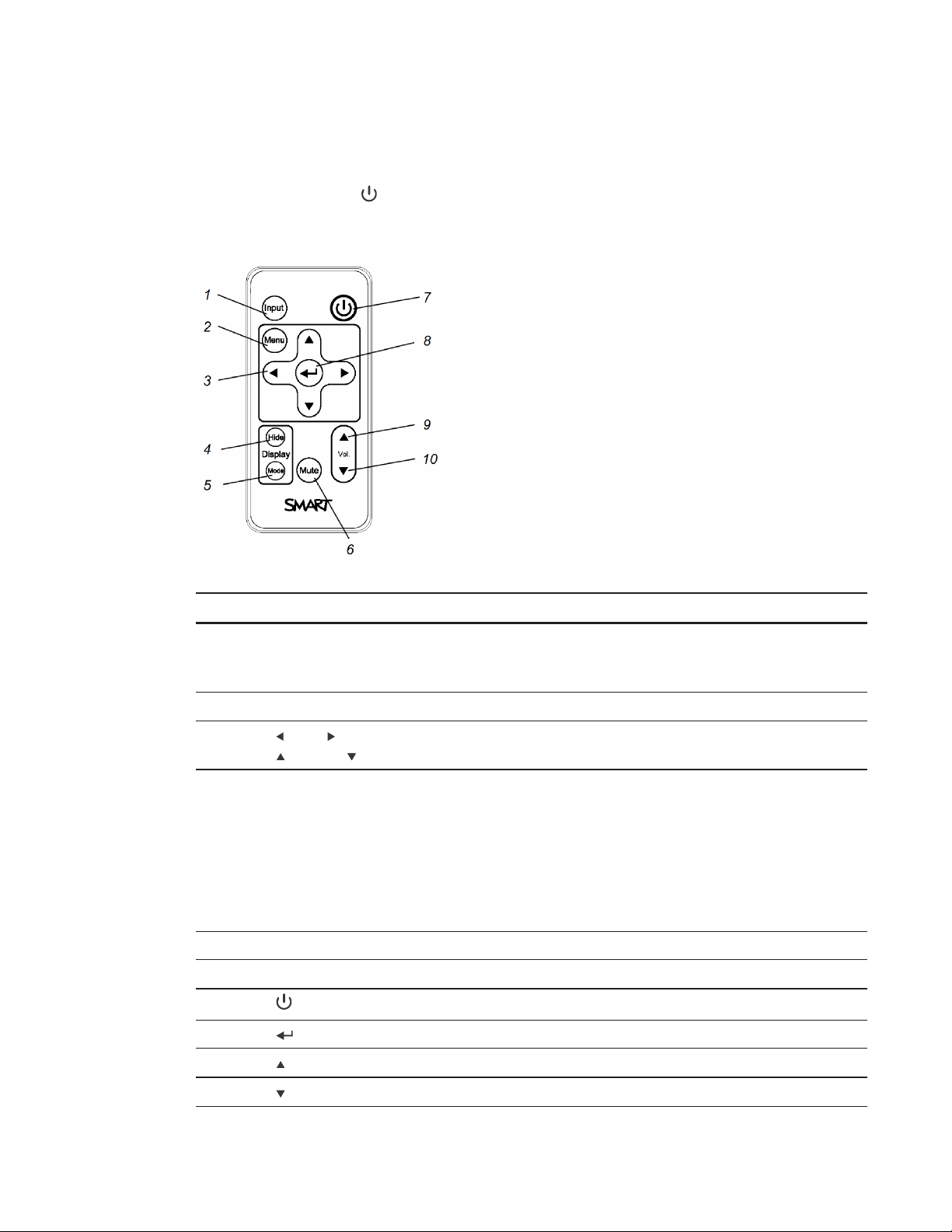
Using t he remote control butt on s
The projector remote control enables you to access on-screen menus and change projector
settings. Use the Power button on the remote control to put the projector into Standby mode or
to turn it on. You can also use the I nput button on the remote control to switch sources on the
projector.
Number Fun ct ion Description
1 Input Select a video and audio input source on the
projector and the associated USB input source on
the ECP, if present.
2 Menu Show or hide the projector menus.
3 (Left), (Right),
Change the menu selections and adjustments.
(Up) and (Down) arrows
4 Hide Freeze, hide or display the image:
Press once to freeze the image.
l
For example, you can display a question on
the screen while you check your e-mail.
Press again to hide the image, that is, to
l
display a black screen.
Press again to return to the live image.
l
5 Mode Select a display mode.
6 Mute Mute audio amplification.
7
(Power)
Turn on the projector or put it into Standby mode.
8 (Enter) Accept the selected mode or option.
9 (Volume Up) Increase audio amplification volume.
10 (Volume Down) Decrease audio amplification volume.
11 smar ttech.com/kb/170910
Page 20
CHAPTER 3
USING THE I NTERACTIVE WHITEBOARD SYSTEM
NOTE
The Mut e, Volume Up and Volume Down buttons work only if there is an audio source
connected to the projector for the selected video input source.
Adjusting project or settings
Use the remote control’s Menu button to access the on-screen display and adjust the projector
settings.
IMPORTANT
Keep the remote control in a safe place because there is no other way to access menu options.
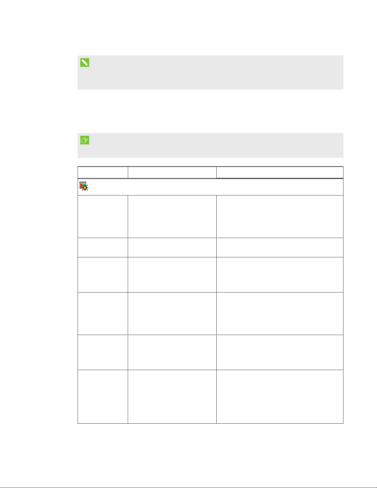
Sett ing Use Notes
Image Adjustment menu (VGA1 input)
Display Mode Indicates the projector’s
display output
(SMARTPresentation,
BrightRoom, DarkRoom,
sRGB and User).
Brightness Adjusts projector brightness
from 0 to 100.
Contrast Adjusts the difference
between the lightest and
darkest parts
of the image from 0 to 100.
Frequency Adjusts the display data
frequency of the projected
image from -5 to 5 to match
the frequency of your
computer’s graphics card.
Tracking Synchronizes your projector’s
display timing with your
computer’s graphics card from
0 to 63.
H-Position Moves the horizontal position
of the source video left or right
from 0 to 100 (relative to the
projected image).
The default is SMAR TPresentat ion.
The default is 50.
The default is 50.
The default is 0.
Don’t adjust this setting unless you’re advised
to by SMARTSupport.
Apply this setting only after you make all
boom adjustments.
This setting is useful in situations where the
source video is cut off.
12 smarttech.com/kb/170910
Page 21
CHAPTER 3
USING THE I NTERACTIVE WHITEBOARD SYSTEM
Sett ing Use Notes
V-Position Moves the vertical position of
the source video up or down
from -5 to 5 (relative to the
projected image).
White Peaking Adjusts the image color
brightness from 0 to 10 while
providing more vibrant white
shades.
Degamma Adjusts the color performance
of the display from 1 to 3.
Color Opens a sub-menu for
adjusting the Red, Green, Blue,
Cyan, Magenta and Yellow
colors on the projector from 0
to 100, providing custom color
and luminance output.
Image Adjustment menu (HDMI1 and HDMI2 inputs)
Display Mode Indicates the projector’s
display output
(SMARTPresentation,
BrightRoom, DarkRoom,
sRGB and User).
Don’t adjust this setting unless you’re advised
to by SMARTSupport.
Apply this setting only after you make all
boom adjustments.
This setting is useful in situations where the
source video is cut off.
A value closer to 0 creates a natural image
and a value closer to 10 increases brightness.
The default is 10.
The default is 2.
Each color has a default value of 100.
Adjustments to the color settings register
under the User mode.
The default is SMAR TPresentat ion.
Brightness Adjusts projector brightness
from 0 to 100.
Contrast Adjusts the difference
between the lightest and
darkest parts of the image from
0 to 100.
White Peaking Adjusts the image color
brightness from 0 to 10 while
providing more vibrant white
shades.
Degamma Adjusts the color performance
of the display from 1 to 3.
13 smarttech.com/kb/170910
The default is 50.
The default is 50.
A value closer to 0 creates a natural image
and a value closer to 10 increases brightness.
The default is 10.
The default is 2.
Page 22
CHAPTER 3
USING THE I NTERACTIVE WHITEBOARD SYSTEM
Sett ing Use Notes
Color Opens a sub-menu for
adjusting the Red, Green, Blue,
Cyan, Magenta and Yellow
colors on the projector from 0
to 100, providing custom color
and luminance output.
Image Adjustment menu (Composite input)
Display Mode Indicates the projector’s
display output
(SMARTPresentation,
BrightRoom, DarkRoom,
sRGB and User).
Brightness Adjusts projector brightness
from 0 to 100.
Contrast Adjusts the difference
between the lightest and
darkest parts
of the image from 0 to 100.
Saturation Adjusts the intensity of the
video signal’s color from 0 to
100.
Each color has a default value of 100.
Adjustments to the color settings register
under the User mode.
The default is SMAR TPresentat ion.
The default is 50.
The default is 50.
The default is 50.
Sharpness Adjusts the video signal’s
sharpness from 0 to 32, with 0
being the maximum sharpness
and 32 being the maximum
smoothness. The default
setting of 16 leaves the video’s
sharpness unaffected.
Tint Adjusts the video signal’s tint
from 0 to 100. Adjusting the
setting toward 0 makes the
image more green. Adjusting
the setting toward 100 makes
the image more magenta.
White Peaking Adjusts the image color
brightness from 0 to 10 while
providing more vibrant white
shades.
Degamma Adjusts the color performance
of the display from 1 to 3.
The default is 16.
The default is 50.
A value closer to 0 creates a natural image
and a value closer to 10 increases brightness.
The default is 10.
The default is 2.
14 smarttech.com/kb/170910
Page 23
CHAPTER 3
USING THE I NTERACTIVE WHITEBOARD SYSTEM
Sett ing Use Notes
Color Opens a sub-menu for
adjusting the Red, Green, Blue,
Cyan, Magenta and Yellow
colors on the projector from 0
to 100, providing custom color
and luminance output.
Audio menu
Line out Enables or disables the line
out.
Microphone Enables or disables the
microphone.
Speaker Enables or disables the
speaker.
Main Volume Adjusts the projector’s volume
amplification from 0 to 40.
Microphone
Volume
Disable Main
Volume Control
Adjusts the microphone’s
volume (gain) from 0 to 40.
Disabling the main volume
control maintains the current
volume setting even if a user
tries to change the volume with
the remote control or volume
buttons on another device.
Each color has a default value of 100.
Adjustments to the color settings register
under the User mode.
The default is on.
The default is on.
The default is on.
The default is 20.
The default is 20.
The default is off.
Mute Mutes the projector’s audio
output.
Closed
Captioning
Turns the display of Closed
Captions on or off.
CC Language Chooses the language for
Closed Captioning.
Advanced Opens the Advanced Audio
sub-menu.
Advanced Audio sub-menu
VGA1 Mic Enables or disables the
microphone input while using
the VGA1 input.
15 smarttech.com/kb/170910
The default is off.
If you mute the projector’s audio output and
then increase or decrease the volume, the
volume is restored automatically. You can
prevent this from happening by disabling the
volume control.
The default is off.
The user can choose between CC1 or CC2.
The default is CC1.
The default is on.
Page 24
CHAPTER 3
USING THE I NTERACTIVE WHITEBOARD SYSTEM
Sett ing Use Notes
VGA1 Speaker Enables or disables the
speaker output while using the
VGA1 input.
HDMI1 Mic Enables or disables the
microphone input while using
the HDMI1 input.
HDMI1 Speaker Enables or disables the
speaker output while using the
HDMI1 input.
HDMI2 Mic Enables or disables the
microphone input while using
the HDMI2 input.
HDMI2 Speaker Enables or disables the
speaker output while using the
HDMI2 input.
Composite Mic Enables or disables the
microphone input while using
the Composite input.
Composite
Speaker
Enables or disables the
speaker output while using the
Composite input.
The default is on.
The default is on.
The default is on.
The default is on.
The default is on.
The default is on.
The default is on.
Microphone
Boost
Boosts the microphone gain by
20dB.
Exit Closes the Advanced Audio
sub-menu.
Operational Settings menu
Signal Detect Enables or disables the
automatic detection of an
active signal source.
Lamp Reminder Turns the lamp replacement
reminder on or off.
Lamp Mode Adjusts lamp brightness to
Standard or Economy.
The default is off.
The default is off.
When On, the projector continuously
switches inputs until it finds an active video
source.
When Off, the projector maintains signal
detection in one input.
This reminder appears 100 hours before the
recommended lamp replacement.
Standard displays a high-quality, bright
image.
Economy increases the lamp life by
decreasing the brightness of the image.
16 smarttech.com/kb/170910
Page 25
CHAPTER 3
USING THE I NTERACTIVE WHITEBOARD SYSTEM
Sett ing Use Notes
ImageCare
Turns ImageCare on or off. The default is off.
Keystone Adjusts the size of the top and
bottom edge with a range of
-15 to 15.
USB 1 Source
Select
USB 2 Source
Select
Maps the USB port to Video
input.
Maps the USB port to Video
input.
Auto Power Off Sets the length of the auto
power-off countdown timer
between 1 and 240 minutes.
Zoom Adjusts the zoom to the center
of the image in or out from 0 to
30.
The default is 0.
Ensure that the top and bottom edges of the
image are horizontal before you position the
left and right edges of the image relative to
the interactive whiteboard.
The default is HDMI1.
The default is VGA1.
The default is 15 minutes.
The timer begins to count down when the
projector no longer receives a video signal.
The timer finishes when the projector enters
Standby mode.
Select 0 to turn off the timer.
Select 120 to enable proper functioning of
ImageCare.
The default is 0.
Zooming in cuts off the outer edges of the
source video.
Projector ID Displays the projector’s unique
ID number (from 000 to 999)
within your organization’s
network.
You can refer to or change this number when
using the network remote management
feature (see
through a network interfa ce
Remotely managing the system
on page51).
17 smar ttech.com/kb/170910
Page 26

CHAPTER 3
USING THE I NTERACTIVE WHITEBOARD SYSTEM
Sett ing Use Notes
Aspect Ratio Adjusts the image output to
FillScreen, MatchInput or
16:9.
Startup Screen Opens the Startup Screen sub-
menu, in which the user can
select the type of startup
screen (SMAR T, Capture User
Start u p Screen, Preview
Start u p Screen), or I mage
Alignment Screen.
The default is FillScreen.
FillScreen produces an image that fills the
entire screen by stretching and scaling the
source video to match the projector’s native
resolution and aspect ratio.
MatchInput displays the source video in its
native resolution and aspect ratio. As a result,
unused space could appear along the top
and bottom edges of the screen (letterbox
format) or along the left and right edges of
the screen (pillarbox format).
16:9 displays the source video in 16:9 aspect
ratio. As a result, unused space appears
along the top and bottom edges of the
screen. This is recommended for use with
HDTV and DVD/Blu-ray discs enhanced for
wide-screen televisions.
See
Video format
on page89 for
descriptions of each mode.
This screen displays when the projector lamp
is starting and a video source signal isn’t
displayed.
SMAR T displays the default SMART logo on
a blue background.
Capture User Start up Screen closes the onscreen display menu and captures the entire
projected image. The captured image is
displayed the next time the on-screen display
opens. (The capture can take up to one
minute, depending on the complexity of the
background graphic.)
Preview St artup Screen enables you to
preview the default or captured startup
screen.
Image Alignment Screen enables you to
adjust the projected image size, shape and
location.
18 smarttech.com/kb/170910
Page 27
CHAPTER 3
USING THE I NTERACTIVE WHITEBOARD SYSTEM
Sett ing Use Notes
Default Opens the Reset to Default
screen, in which the user can
resets the projector settings to
their default values.
Network menu
Network and
VGAOut
Activates the projector’s RJ45
(8P8C) connector and network
features.
Status Displays the current network
status (Connect ed, or
Disconn ected).
DHCP Displays the status of the
network’s Dynamic Host
Configuration Protocol (DHCP)
as On or Off.
If you select Y es, all projector settings reset
to their defaults, reversing any menu changes
you made. This action is irreversible.
Don’t adjust this setting unless you want to
reset all of the applied settings, or unless
you’re advised to by a SMARTSupport
specialist.
The default is Disconnect ed.
The default is off.
On enables a DHCP server on the network to
assign an IP address to the projector
automatically.
Off enables an administrator to assign an IP
address manually.
Password
Reminder
Emails the network password
to the email address selected
in advance.
IP Address Displays the projector’s current
IP address in values between
0.0.0.0 and 255.255.255.255.
Subnet Mask Displays the projector’s subnet
mask number in values
between 0.0.0.0 and
255.255.255.255.
Gateway Displays the projector’s
network gateway in values
between 0.0.0.0 and
255.255.255.255.
See
Web page management
on page51 to
set up a destination email address.
To change the projector’s IP address, use the
RS-232 connector or use a DHCP server to
assign a dynamic IP address, and then set a
static IP address using the network remote
management feature (see
Remotely
managing the system through a network
interface
on page51).
19 smarttech.com/kb/170910
Page 28

CHAPTER 3
USING THE I NTERACTIVE WHITEBOARD SYSTEM
Sett ing Use Notes
DNS Displays the projector’s
domain name server IP
address in values between
0.0.0.0 and 255.255.255.255.
MAC Address Displays the projector’s MAC
address in xx-xx-xx-xx-xx-xx
format.
Group Name Displays the projector’s
workgroup name as set by an
administrator (maximum 16
characters).
Projector Name Displays the projector’s name
as set by an administrator
(maximum 16 characters).
Location Displays the projector’s
location as set by an
administrator (maximum 16
characters).
Contact Displays the contact email
address for projector support
as set by an administrator
(maximum 16 characters).
You can set the projector’s workgroup name
using the remote management features (see
Remotely managing the system through a
network interface
on page51 and
Remotely
managing the system through an RS-232
serial interface
on page61).
You can set the projector’s name using the
remote management features (see
Remotely
managing the system through a network
interface
on page51 and
Remotely
managing the system through an RS-232
serial interface
on page61).
You can set the projector’s location using the
remote management features (see
Remotely
managing the system through a network
interface
on page51 and
Remotely
managing the system through an RS-232
serial interface
on page61).
You can set the contact name or number
using the remote management features (see
Remotely managing the system through a
network interface
on page51 and
Remotely
managing the system through an RS-232
serial interface
on page61).
20 smarttech.com/kb/170910
Page 29
CHAPTER 3
USING THE I NTERACTIVE WHITEBOARD SYSTEM
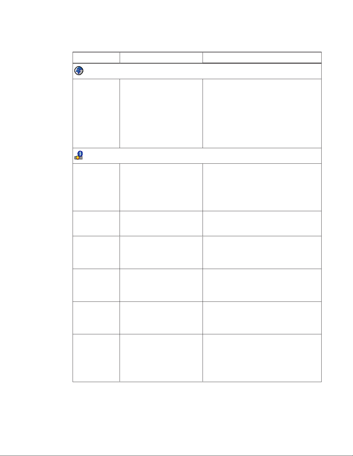
Sett ing Use Notes
Language menu
Language Selects the language used in
the projector menus.
Informat ion menu
Lamp Hours Displays the current number of
lamp usage hours from 0 to
9999 hours from when it was
last reset.
Input Displays the currently active
video input source (VGA1,
Composite, HDMI1, or HDMI2).
Resolution Displays the projector’s most
recently detected video
source signal resolution and
refresh rate.
Projector menu support is available in English
(U.S.), English (UK) French, German, Dutch,
Danish, Finnish, Italian, Norwegian, Russian,
Spanish, Swedish, Portugese, Chinese
(Simplified), Chinese (Traditional), Czech,
Hungarian, Japanese, Malayasian, Polish,
Romanian, Arabic, Turkish, Greek, Slovak,
Korean and Hebrew. (U.S. English is the
default.)
Always reset the lamp hours after you
replace a lamp, because lamp service
reminders are based on the current hours of
use. See
Resetting the la mp hours
on
page36 for details on the lamp hours reset
procedure.
Default is VGA1.
If no video source is currently active, this
setting displays the last known source signal
image resolution and refresh rate.
DDP Displays the projector’s digital
display processor (DDP)
firmware version in x.x.x.x
format.
MPU Displays the projector
microprocessor unit (MPU)
firmware version in x.x.x.x
format.
Network Version When the Network and VGA
Out setting is enabled,
displays the projector’s
network communications
processor firmware version in
x.x.x.x format.
21 smarttech.com/kb/170910
If the Network and VGA Out setting is not
enabled, 0.0.0.0 appears.
Page 30
CHAPTER 3
USING THE I NTERACTIVE WHITEBOARD SYSTEM
Sett ing Use Notes
Model Number Displays the projector’s model
number (SMART U100 or
SMAR T U100w).
Serial Number Displays the projector’s serial
number.
Focusing the image
Use the projector’s focus slider to focus the projected image.
To focus the image
Adjust the Focus slider until the image is in focus.
22 sm arttech.com/kb/170910
Page 31

CHAPTER 3
USING THE I NTERACTIVE WHITEBOARD SYSTEM
Adjusting the image
Refer to these notes when adjusting the projected image, as described in the included
SMARTBoard M600ix3 interactive whiteboa rd system installation guide
(smarttech.com/kb/170886).
l While adjusting the projected image size, shape and location, use the projector’s default
background so that you can see the full projected image clearly. Don’t use other images,
which might be cropped or scaled by the projector and could result in a misleading projected
image size, shape and location.
l Use the mechanical adjustments described in the installation document to make all physical
image adjustments. Don’t use the projector’s on-screen menu options during the projector
alignment process.
l Be aware that as you tilt the projector up or lower its mounting boom to raise the image, the
entire projected image increases or decreases in size, especially at the bottom of the
projected image.
l When adjusting keystone (tilt), ensure that the top and bottom edges of the image are
horizontal before you position the left and right edges of the image relative to the interactive
whiteboard.
l When you move the projector forward or backward on the boom to make the image larger or
smaller, you might need to tilt or turn the projector slightly to keep the image square. Loosen
the lever slightly to aid in this adjustment.
l To fine-tune the image, you might need to repeat all steps described in the installation
document in smaller increments.
Projector connection diagram
You can connect a variety of peripheral devices to the projector, including DVD/Blu-ray players,
VCRs, HDMI streaming devices, document cameras, digital cameras and high-definition sources, as
well as peripheral device outputs, such as a secondary projector or a flat-panel display and
powered speakers.
NOTE
You might need to purchase third-party adapters to connect certain peripheral devices.
23 smarttech.com/kb/170910
Page 32

CHAPTER 3
USING THE I NTERACTIVE WHITEBOARD SYSTEM
No. Connect or Connect to:
1 USB B Computer (for service access only)
2 DB15F (DE-15F) RGB video output (VGA
Secondary display (not included)
Out)
3 DB15F (DE-15F) RGB video input (VGA1) Primary computer (not included)
4 RCA Composite video input Video source (not included)
5 HDMI1 and HDMI2 inputs High-definition video and audio sources
(not included)
6 3.5 mm phone jack VGA1 audio input Audio sources associated with primary
and secondary computers
7 Right RCA audio input
Audio source for composite video (not
included)
8 Left RCA audio input
Audio source for composite video (not
included)
9 3.5 mm phone jack microphone Microphone (not included)
10 3.5 mm phone jack audio output Speakers (not included)
11 DB9F (DE-9F) RS-232 Room control system or other terminal
device (not included)
12 7-pin mini-DIN ECP control
13 4-pin power mini-DIN 5V/2A output ECP power (5v/2A)
14 RJ45 (8P8C) Network (for web page management and
SNMP access)
15 USB A receptacle, power only +5 VDC HDMI streaming device (not included)
16 Power Mains power supply
24 smarttech.com/kb/170910
Page 33

CHAPTER 3
USING THE I NTERACTIVE WHITEBOARD SYSTEM
NOTES
l To connect the interactive whiteboard, see the
whiteboard system installation guide
l To connect accessories to the interactive whiteboard, refer to the documents included with
(smarttech.com/kb/170886).
SMARTBoard M600ix3 interactive
the accessories and consult the SMARTSupport website (smarttech.com/support) for
additional information.
Using the interactive whiteboard
Refer to the
(smarttech.com/kb/170410) for in-depth information on using the interactive whiteboard and its
features.
When you connect the SMARTBoard interactive whiteboard to a computer that has SMART
software installed, you can access the interactive whiteboard‘s full capabilities.
For additional resources, go to smarttech.com/support, where you’ll find up-to-date, product-
specific information, including setup instructions and specifications.
The SMARTtraining website (smarttech.com/training) includes an extensive library of training
resources you can consult as you learn to set up or use the interactive whiteboard system.
SMARTBoard M600 series interactive whiteboa rd user’s guide
25 smarttech.com/kb/170910
Page 34

Page 35

Chapter 4
whiteboard system
Maintaining the interactive whiteboard 27
Preventing damage to the interactive whiteboard 27
Keeping the writing surface clean 28
Cleaning the projector 28
Focusing and adjusting the projector image 29
Replacing the projector lamp 29
Removing and replacing the projector lamp module 29
Resetting the lamp hours 36
This chapter includes methods for properly cleaning and preventing damage to the SMARTBoard
interactive whiteboard system.
Maintaining the interactive whiteboard
For information on maintaining the interactive whiteboard, see the
whiteboard installa tion guide
With proper care, the SMARTBoard interactive whiteboard will provide years of trouble-free
service.
(smarttech.com/kb/170555).
Preventing damage to the interactive whiteboard
Although the interactive whiteboard’s surface is very durable, take the following precautions to
prevent damage.
l Don’t use sharp or pointed objects, such as ballpoint pens or pointers, as writing tools.
l Replace the pen nib when the nib wears out.
l Don’t use low-odor dry-erase markers because they can be very difficult to erase. Use
standard (high-odor) dry-erase markers that show a warning to use them only in well-ventilated
areas.
l Don’t use adhesive tape on the interactive surface.
SMARTBoard M600 interactive
27 smar ttech.com/kb/170910
Page 36

CHAPTER 4
MAIN TAINING THE INTERACTIVE W HI TEBOARD SYSTEM
l Don’t use abrasive erasers or harsh chemicals to clean the product.
l The digital cameras located in the corners of the frame are protected from dust and dirt by
windows. In extremely dusty environments, spray an alcohol-free household glass cleaner,
such as Windex® cleaner, on a cotton swab and rub it gently on the windows. Don’t use
compressed air to clean the cameras.
Keeping the writing surface clean
Follow these tips to keep the interactive whiteboard’s surface clean.
l Clean the interactive whiteboard at least every six months.
l Don’t spray cleaner directly onto the interactive whiteboard’s surface. Instead, spray a light
amount of cleaner on a cloth and then gently wipe the interactive surface.
l
IMPORTANT
Turn off the interactive whiteboard system before you clean it so that you do not scramble
the desktop icons or inadvertently activate applications when you wipe the interactive
surface.
TIP
To view dirt or streaks more easily, set the projector to Standby (lamp off) mode.
Cleaning the projector
WARNI NG
Cleaning a wall-mounted projector can result in a fall or injury. Use caution when climbing a
ladder, and consider removing the projector from its wall-mounting bracket to clean it.
CAUTION
l Never scrub the mirror cover with a cleaning cloth or touch the mirror cover with your hands
or a brush. Instead, clean the mirror cover as you would clean a lens, using lens cleaning
tissue and no solvents. Do not apply pressure to the mirror cover, and do not use cleaning
products designed for touch screens or monitors.
Before you clean the projector, press the Power button twice on the remote control to
l
put the system in Standby mode, and then allow the lamp to cool for at least 30 minutes.
28 sm arttech.com/kb/170910
Page 37

CHAPTER 4
MAIN TAINING THE INTERACTIVE W HI TEBOARD SYSTEM
l Do not spray cleaners, solvents or compressed air directly on the projector. Do not use
spray cleaners or solvents near any part of the projector because they can damage or stain
the unit. Spraying the system could spread a chemical mist on some of the projector’s
components and lamp, resulting in damage and poor image quality.
l Do not allow liquids or commercial solvents of any kind to flow into the projector base or
head.
l If wiping the mirror cover is unavoidable, wear protective gloves and gather the cleaning
cloth into a ball. Gently run the cleaning cloth across the lens mirror from the center to the
edge, using the cleaning cloth as you would a feather duster. Don’t apply pressure to the
mirror cover.
IMPORTANT
l When cleaning the interactive whiteboard system:
o
Wipe the exterior of the projector with a lint-free cloth.
o
If necessary, use a soft cloth moistened with a mild detergent to clean the projector
housing.
l Do not use abrasive cleaners, waxes or solvents.
Focusing and adjusting the projector image
For information on focusing and adjusting the projector image, see
page22 and
Adjusting the ima ge
on page23.
Focusing the image
on
Replacing the projector lamp
This section provides instructions for replacing the projector lamp module.
Removing and replacing the projector lamp module
Eventually the lamp will dim and a message will appear reminding you to replace the lamp. Make
sure you have a replacement lamp module before you proceed with the following instructions.
29 smarttech.com/kb/170910
Page 38

CHAPTER 4
MAIN TAINING THE INTERACTIVE W HI TEBOARD SYSTEM
WARNI NG
l See smarttech.com/compliance for the projector’s MSDS documents.
l Replace the lamp module when the projector displays its lamp life warning message. If you
continue to use the projector after this message appears, the lamp can shatter or burst,
scattering glass throughout the projector.
l If the lamp shatters or bursts, leave and then ventilate the area.
Next do the following:
o
Avoid touching the glass fragments because they can cause injury.
o
Wash your hands thoroughly if you have come into contact with lamp debris.
o
Thoroughly clean the area around the projector, and discard any edible items placed in
that area because they could be contaminated.
o
Call your authorized SMART reseller for instructions. Do not attempt to replace the
lamp.
l Replacing the lamp module in a wall-mounted projector can result in a fall or injury. Use
caution when climbing a ladder, and consider removing the projector from the wall-
mounting bracket to replace the lamp module.
l Uncovering the lamp while the projector is mounted on the wall-mounting bracket can lead
to product damage or personal injury from falling pieces of glass if the lamp is broken.
30 smarttech.com/kb/170910
Page 39

CHAPTER 4
MAIN TAINING THE INTERACTIVE W HI TEBOARD SYSTEM
l When replacing the projector lamp module:
o
Put the projector into Standby mode and wait 30 minutes for the lamp to cool
completely.
o
Do not loosen or remove any screws other than those specified in the lamp
replacement instructions.
o
Wear protective eyewear while changing the lamp module. Failure to do so can cause
injuries including loss of eyesight if the lamp shatters or bursts.
o
Use only replacement lamp modules approved by SMARTTechnologies. Contact your
authorized SMART reseller for replacement parts.
o
Never replace the lamp module with a previously used lamp module.
o
Always handle the fragile lamp assembly with care to prevent premature lamp failure or
exposure to mercury. Use gloves when touching the lamp module. Do not touch the
lamp with your fingers.
o
Recycle or dispose of the lamp module as hazardous waste in accordance with local
regulations.
You need a Phillips No. 2 screwdriver to complete these procedures.
To remove t he old lamp module
Switch off the power to the projector by pressing the Power button on the remote control.
1.
2. Allow the projector to cool for at least 30 minutes.
3. Disconnect the power cable from the projector.
31 smarttech.com/kb/170910
Page 40

CHAPTER 4
MAIN TAINING THE INTERACTIVE W HI TEBOARD SYSTEM
4. Open the lamp cover.
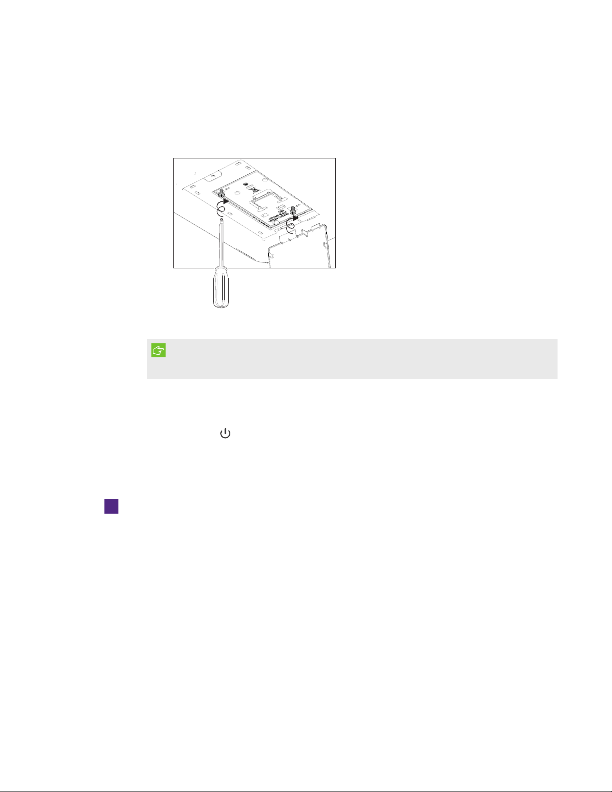
5. Use a Phillips screwdriver to loosen the two captive screws from the bottom of the lamp
module.
NOTE
Don’t try to remove these screws. Captive screws can’t be removed, only loosened.
6. Pull up the lamp handle carefully.
32 smarttech.com/kb/170910
Page 41

CHAPTER 4
MAIN TAINING THE INTERACTIVE W HI TEBOARD SYSTEM
7. Remove the lamp module
33 smarttech.com/kb/170910
Page 42

CHAPTER 4
MAIN TAINING THE INTERACTIVE W HI TEBOARD SYSTEM
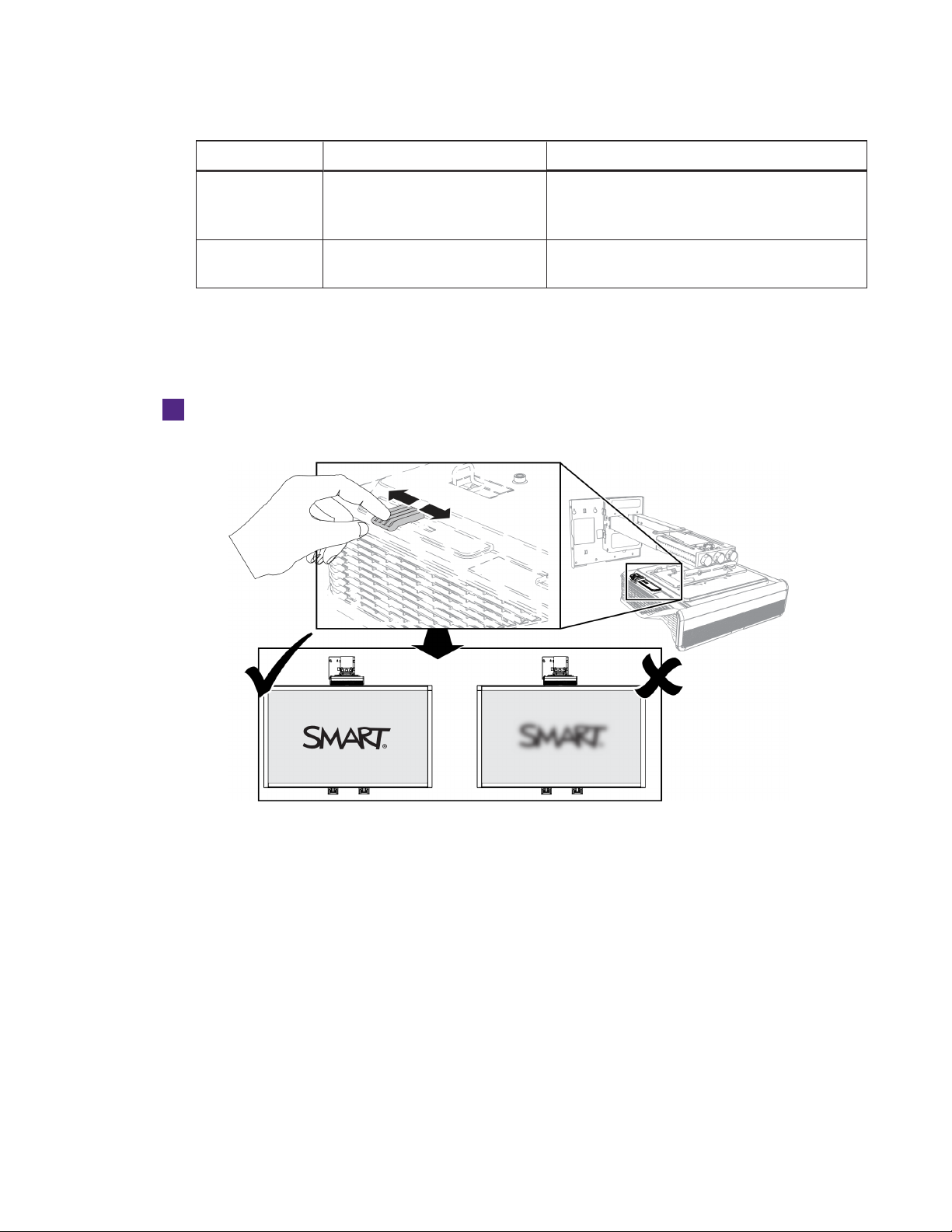
To put t he new lamp module into t h e projector
1. Remove the new lamp module from its packaging.
2. Carefully place the lamp module into the projector and gently press the power end of the
lamp module against the projector to ensure the power plug makes contact with the
projector’s power receptacle.
NOTE
You should be able to place the lamp module into the projector easily without applying
much force.
34 smarttech.com/kb/170910
Page 43
CHAPTER 4
MAIN TAINING THE INTERACTIVE W HI TEBOARD SYSTEM
3. Use the Phillips screwdriver to secure the captive screws.
IMPORTANT
Do not over-tighten the screws.
4. Close the lamp cover.
5. Connect the power cable to the wall outlet.
Press the Power button once on the remote control to confirm that the projector is
6.
operating and that the lamp module is correctly installed.
7. Put the old lamp module in a secure container, and handle it gently until you recycle it.
To finish the projector lamp module installat ion
1. Turn on the projector.
2. Adjust the projector image if necessary (see
3. Access the service menu to reset the lamp hours (see
Adjusting the ima ge
Resetting the la mp hours
on page23).
on the next
page).
4. Activate the projector’s alert emails and lamp warnings if they’ve been deactivated (see
alerts
on page57 and
Control pa nel
on page52).
Ema il
35 smarttech.com/kb/170910
Page 44

CHAPTER 4
MAIN TAINING THE INTERACTIVE W HI TEBOARD SYSTEM
Resetting the lamp hours
After you replace the lamp module, access the projector service menu to reset the lamp hours. To
prevent errors, only a system administrator should perform this procedure.
NOTE
Always reset the lamp hours after you replace the lamp, because lamp service reminders are
based on the current hours of use.
To reset the lamp hours
1. Using the remote control, press the following buttons quickly to access the service menu:
Down, U p, U p, Left, Up.
CAUTION
Do not adjust any settings in the service menu other than those listed in this guide. Changing
other settings can damage or affect the operation of the projector and may invalidate the
warranty.
2. Scroll down to
Lamp Hour Reset
, and then press OK.
CAUTION
Do not reset the lamp hours unless you have just replaced the lamp module. Resetting the
lamp hours on an old lamp can damage your projector as a result of lamp failure.
NOTE
The
Display Hour
value cannot be reset because it’s the running total of hours the projector
has been in use.
3. Press the Menu button on the remote control.
The
SMART U100 Settings
Select to confirm that
4.
menu appears.
Lamp Hour
is reset to zero.
36 smarttech.com/kb/170910
Page 45

Chapter 5
whiteboard system
Before you start 38
Locating status lights 38
Locating serial numbers 39
Determining the interactive whiteboard system’s status 39
U100 and U100w projector status lights 40
Resolving interactive whiteboard issues 42
Resolving operation issues 42
Resolving projector errors 42
The projector stops responding 42
The “Lamp Failure” message appears 43
The projector Power and Service lights are off 43
Resolving image issues 43
Loss of signal 44
Partial, scrolling or incorrectly displayed image 44
Unstable or flickering image 45
Frozen image 46
The image doesn’t fit the interactive whiteboard 46
The image from a connected laptop computer isn’t projected 46
Unaligned projected image 47
Resolving audio issues 47
Resolving network communication issues 48
Accessing the service menu 48
Retrieving your password 49
Resetting the projector 49
Transporting the interactive whiteboard system 49
37 smarttech.com/kb/170910
Page 46

CHAPTER 5
TROUBLESHOOTING THE INTERACTIVE WHITEBOARD SYSTEM
This chapter provides basic troubleshooting information for the interactive whiteboard system.
For issues not covered in this chapter, consult the SMARTSupport website
(smarttech.com/support) or contact your authorized SMART reseller (smarttech.com/where).
Before you start
Before you troubleshoot the interactive whiteboard system or contact SMARTSupport or your
authorized SMART reseller for assistance, you need to do the following:
l Locate the interactive whiteboard system’s status lights.
l Locate the interactive whiteboard system’s serial numbers.
Locating status lights
The interactive whiteboard system consists of several components, and each has its own status
light:
l The Select button on the interactive whiteboard's pen tray also functions as a status light.
The projector’s Power , Service light, and Diagnostic Indicator are located on the bottom
l
of the projector.
38 smarttech.com/kb/170910
Page 47
CHAPTER 5
TROUBLESHOOTING THE INTERACTIVE WHITEBOARD SYSTEM
Locating serial numbers
The SMARTBoard M600 interactive whiteboard serial number is located on the lower-right edge
of the frame, as well as on the back of the interactive whiteboard. For more information, see the
SMARTBoard M600 series interactive whiteboa rd user’s guide
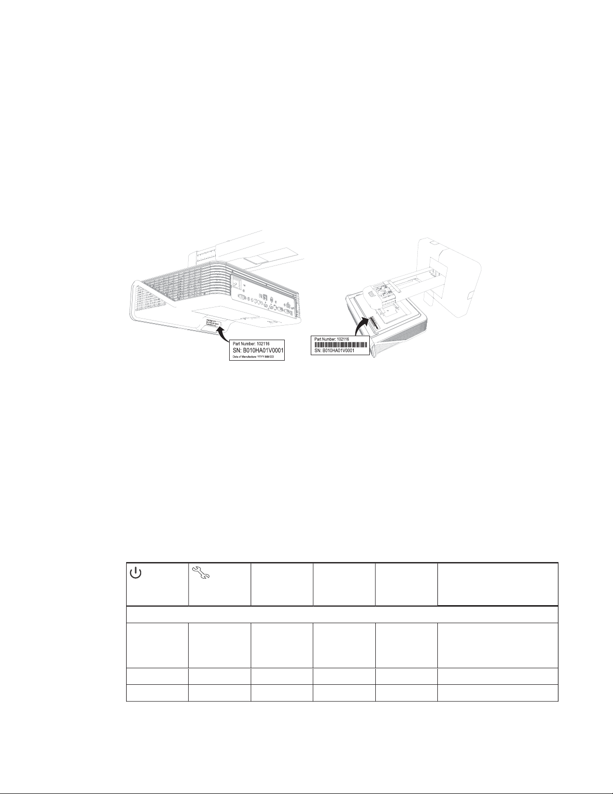
The SMARTU100 and U100w projector’s serial number is located in two places: one next to the
mirror cover and the other on the top of the projector.
(smarttech.com/kb/170410).
For the locations of serial numbers on other components and accessories, see
smarttech.com/support.
Determining the interactive whiteboard system’s status
Use the following table to determine the status of your interactive whiteboard system.
Pen tray Select
Projector Power
light
Normal operating statuses
Solid green Off Solidwhite Correct Full control The system is operating normally.
Flashing green Off Off None None The system is starting up.
Solid am ber Off Off None N one The system is in Standby mode.
Projector Service
light
button status light
Projected im age Touch and pen
control
Stat us and related troubleshooting
If image or sound issues occ ur, see
the remaining sections of this chapter
for troubleshooting information.
39 smarttech.com/kb/170910
Page 48

CHAPTER 5
TROUBLESHOOTING THE INTERACTIVE WHITEBOARD SYSTEM
Pen tray Select
Projector Power
light
Flashing am ber Off Off None N one The system is entering Standby
Solid green Off Solidamber N/A None The interact ive whiteboard’s
Error statuses
Solid green Off Solidwhite Incorrect Full c ontrol There’san issue with the projected
Solid green Off Solidwhite Correct None There’s an issue with the interactiv e
Solid green Off Flashing white Correct Touch only SMARTProductDrivers isn’t installed
Solid green Off Off N/A None There’s an issue with the c onnections
Solid am ber Flashing red N/A None N/A There’s an issuewith the projector
Off Flashing red Off None None The projector’s operating
Off Solid red N /A None N/A There’san issue with t he projector’s
Off Off Off None None The projector power cable isn’t
Projector Service
light
button status light
Projected im age Touch and pen
control
Stat us and related troubleshooting
mode.
controller module is ready t o receive
a firmware update or is applying a
firmware update.
image.
See
Resolving image issues
page43.
whiteboard.
See
Resolving operation issues
page42.
or isn’t runningcorrectly on the
connected computer.
between the interactive whiteboard
and the other c omponents of the
system.
See
Resolving interactive whiteboard
issues
on page42.
lamp.
See
The “L amp Failure” message
appears
on page43.
temperature has been exceeded.
See
Resolving projector errors
page42.
fan or c olor wheel.
See
Resolving projector errors
page42.
properly c onnected.
OR
There’s an issue with the mains power
supply (for example, the circuit
breaker is off ).
on
on
on
on
U100 and U100w projector status lights
A code appears on the projector’s diagnostic indicator if the projector encounters an error. Use the
following table to interpret the codes.
40 sm arttech.com/kb/170910
Page 49

CHAPTER 5
TROUBLESHOOTING THE INTERACTIVE WHITEBOARD SYSTEM
Lamp state Power LED P rojector
On Solid green Solid red Lh L h = Lam p hours reminder
Off Flashing red Flashing
Off after
failing to
turn on
Off Flashing red Flashing red OH OH = Thermal sensor overheat
Off Flashing red Flashing red dH dH = Lam p driver overheat
Off Solid red Solid red LF LF = Lamp failure If the condition persists, replace the
Flashing
amber
Service light
amber
Flashing
amber
Diagnostic
Indicator
After the projector starts, a message
appearson-screen t ellingthe user to
replace the lamp soon. The message
disappearsafter a moment. The Lh
code remains.
LH LH = Lam p v oltage too high
The projector has detected that t he
lamp voltage is too high for safe
operation.
LF LF = Lam p failure
The lamp failed to turn on aft er
several att empts.
The projector has over-heated and
shut down automatically . The
system can be restarted to resume
normal operation.
The projector has over-heated and
shut down automatically . The
system can be restarted to resume
normal operation.
LH LH = Lam p v oltage too high Replace the lamp.
F1 F1 = System fan 1 failure Contact SMART Support.
F2
F2 = System f an 2 failure
Description Remedy
Order a new lamp soon.
Replace t he lam p.
Wait 20 m inutes, and then try to
turn t he projector on again.
If the condition persists, replace t he
lamp.
The projector may require cleaning,
or the operating environment is too
hot. It m ay be possiblet o resume
normal operation if t he lam p has
beenturned off for at least 30
minutes and operatingenvironment
has cooled down.
The projector may require cleaning,
or the operating environment is too
hot. It m ay be possiblet o resume
normal operation if t he lam p has
beenturned off for at least 30
minutes and operatingenvironment
has cooled down.
lamp.
41 smarttech.com/kb/170910
F3
F4
FC FC = Color wheel failure
PS
FP
Fd Fd = D mD failure
Fb Fb = Lamp driver (ballast) failure
F3 = System fan 3 failure
F4 = Blower fan f ailure
PS = 12 VD C f ailure
FP = D DP processor failure
Page 50

CHAPTER 5
TROUBLESHOOTING THE INTERACTIVE WHITEBOARD SYSTEM
Resolving interactive whiteboard issues
This section includes information on resolving issues with the interactive whiteboard.
For information not covered in this section, see the
whiteboard user’s guide
(smarttech.com/kb/170410).
SMARTBoard M600 series interactive
Resolving operation issues
To resolve operation issues, complete the following tasks:
l Confirm that all cables are securely connected to the back of the pen tray, computer and
control module.
l Perform the calibration procedure documented in the
whiteboard user’s guide
l Reset the interactive whiteboard system by disconnecting the power cable from the wall
outlet and then connecting it.
l If necessary, complete additional troubleshooting with the guidance of SMARTSupport using
SMARTBoard Diagnostics.
(smarttech.com/kb/170410).
SMARTBoard M600 series interactive
Resolving projector errors
System administrators can resolve the following projector errors on their own before contacting
SMARTSupport. Performing initial troubleshooting on the projector reduces the time of a support
call.
The projector stops responding
If the projector stops responding, perform the following procedure.
To restart an unresponsive projector
1. Put the projector into Standby mode, and then wait 30 minutes for it to cool down.
2. Disconnect the power cable from the power outlet, and then wait at least 60 seconds.
3. Connect the power cable, and then turn on the projector.
42 smarttech.com/kb/170910
Page 51

CHAPTER 5
TROUBLESHOOTING THE INTERACTIVE WHITEBOARD SYSTEM
The “Lamp Failure” message appears
If the “Lamp Failure” message appears, one of the following issues is occurring:
l The lamp is overheating, likely due to blocked air vents.
l The lamp has reached the end of its life.
l The projector has an internal problem.
To resolve the “Lamp Failure” err or
1. Replace the lamp module as described in
module
on page29.
Removing a nd replacing the projector lamp
2. If replacing the lamp module doesn’t resolve the issue, put the projector into Standby mode,
disconnect the power cable, and then contact your authorized SMARTreseller.
The projector Power and Service lights are off
If the projector Power and Service lights are both off, one of the following issues is occurring:
l There was a power outage or a power surge.
l A circuit breaker or a safety switch was tripped.
l The projector isn’t connected to the power source.
l The projector has an internal problem.
To resolve the unlit projector Power and Service lights issue
1. Check the power source, and then make sure that all cables are connected.
2. Confirm that the projector is connected to an active power outlet.
3. Make sure the pins on the connectors aren’t broken or bent.
4. Connect the power cable, and then turn on the projector.
5. If the previous steps don’t resolve the issue, disconnect the power cable and then contact
your authorized SMARTreseller.
Resolving image issues
To resolve common image issues, complete the following tasks:
l Ensure the computer or other video source is on and set to display a resolution and refresh
rate supported by the projector (see
l Ensure the video source is properly connected to the projector.
43 smarttech.com/kb/170910
Video format
on page89).
Page 52

CHAPTER 5
TROUBLESHOOTING THE INTERACTIVE WHITEBOARD SYSTEM
l Press the I nput button on the remote control or the Input Select button on the pen tray to
switch to the correct video source.
If these tasks don’t resolve the issue, refer to the following sections for additional troubleshooting
information.
Loss of signal
If a video source signal isn’t detected, if it’s out of range of the projector’s support video modes or
if the signal is being switched to a different device or input, the projector doesn’t show a source
signal and instead displays the SMART logo on a blue screen.
To resolve signal loss issues
1. Wait approximately 45 seconds for the image to synchronize. Some video signals require
more time to synchronize. Cycling through the inputs can also help image synchronization.
2. If the image doesn’t synchronize, check the cable connections to the projector.
3. Ensure that the image signal is compatible with the projector (see
Video format
on page89).
4. If there are any extension cables, switch boxes, connection wall plates or other devices in the
video connection from the computer to the projector, temporarily remove them to ensure
they aren’t causing the video signal loss.
5. If the projector still doesn’t show a source signal, contact your authorized SMART reseller.
Partial, scrolling or incorrectly displayed image
NOTE
This procedure may vary depending on the version of Windows® operating system or MacOSX
operating system software and your system preferences. The following procedures apply to
Windows 7 operating systems and MacOSX10.8 operating system software.
44 smarttech.com/kb/170910
Page 53

CHAPTER 5
TROUBLESHOOTING THE INTERACTIVE WHITEBOARD SYSTEM
To resolve a partial, scrolling or incorrectly displayed image on a Windows comput er
1. Select St art > Control Panel.
2. Click Display, and then select Adjust resolution.
3. Verify that the display resolution is set to 1024 × 768 (SMARTU100 projector) or 1280 × 800
(SMARTU100w projector in 16:10 aspect ratio mode).
4. Click Advanced sett in gs, and then click the Monitor tab.
5. Verify that the screen refresh rate is 60 Hz.
To resolve a partial, scrolling or incorrectly displayed image on a Mac comput er
1. Select Apple Menu > System Preferences.
The
System Preferences
dialog box appears.
2. Click Displays.
3. Verify that the display resolution is set to 1024 × 768 (SMARTU100 ) or 1280 × 800
(SMARTU100w in 16:10 aspect ratio mode).
4. Verify that the screen refresh rate is 60 Hz.
Unstable or flickering image
If the projector’s image is unstable or flickering, the frequency or tracking settings on the input
source could be different from the settings on the projector.
IMPORTANT
Write down the current settings before adjusting any of them in the following procedure.
To resolve an unstable or flickering image
1. Check the display mode of your computer’s graphics card. Make sure it matches one of the
projector’s compatible signal formats (see
computer’s manual for more information.
2. Configure the display mode of your computer’s graphics card to make it compatible with the
projector. Refer to your computer’s manual for more information.
Video format
on page89). Refer to your
3. Adjust the frequency, tracking, H-position and V-position settings in the on-screen menu. See
Adjusting projector settings
45 smarttech.com/kb/170910
on page12.
Page 54

CHAPTER 5
TROUBLESHOOTING THE INTERACTIVE WHITEBOARD SYSTEM
4. Optionally, reset the projector as described in
the frequency and tracking to their original values.
IMPORTANT
This action resets all values to their defaults.
Resetting the projector
on page49 to adjust
Frozen image
If the projector has a frozen image, perform the following procedure.
To resolve a frozen image
1. Ensure that the Hide Display feature is off.
2. Press the Hide button on the projector’s remote control to hide or show the display.
3. Ensure that the source device, such as the DVD player or computer, isn’t malfunctioning.
4. Put the projector into Standby mode, and then wait 30 minutes for it to cool down.
5. Disconnect the power cable from the power outlet, and then wait at least 60 seconds.
6. Connect the power cable, and then turn on the projector.
7. If the previous steps don’t resolve the issue, contact your authorized SMARTreseller.
The image doesn’t fit the interactive whiteboard
If you’re using a SMARTU100w projector with a wide screen interactive whiteboard, verify that
you’re using the correct aspect ratio mode for the interactive whiteboard:
Int eractive whit eboard Aspect rat io mode
SMARTBoard M685 interactive whiteboard 16:10
You can set the aspect ratio mode using the Native DLP Resolution setting in the Projector
Functions menu (see
Adjusting projector settings
on page12).
The image from a connected laptop computer isn’t projected
Laptop computer settings can interfere with projector operations.
Some laptop computers deactivate their screens when you connect a secondary display. Refer to
your computer’s manual for details on reactivating the computer's display screen.
46 smarttech.com/kb/170910
Page 55

CHAPTER 5
TROUBLESHOOTING THE INTERACTIVE WHITEBOARD SYSTEM
Unaligned projected image
Alignment errors occur when the projected image isn’t perpendicular to the screen. Alignment
errors can occur when if the interactive whiteboard system is mounted on an uneven surface or a
wall that has obstructions, or if the projector is swiveled too far from the interactive whiteboard’s
vertical center.
Use the instructions in the
SMARTBoard M600ix3 interactive whiteboa rd system installation guide
(smarttech.com/kb/170886) to eliminate most image alignment issues.
The projector image can slip if the projector is moved often or installed in a location prone to
vibration, such as next to a heavy door. Follow these precautions to help prevent the image from
becoming unaligned:
l Make sure that the installation wall is plumb and square and doesn’t move or vibrate
excessively.
l Make sure that there are no obstructions behind the projector’s wall-mounting bracket, and
that the bracket is firmly secured to the wall according to the installation instructions.
l Adjust the projected image. See the
installation guide
(smarttech.com/kb/170886) and
SMARTBoard M600ix3 interactive whiteboa rd system
Adjusting the ima ge
on page23.
Resolving audio issues
The projector includes an integrated speaker. You can also connect an external audio system to
the audio output connector in the projector’s connection panel. If sound isn’t coming from either
the internal speaker or the external audio system, perform the following procedures.
NOTE
You might need to configure your computer to pass audio through HDMI if it isn’t configured
automatically.
To resolve audio issues
1. Ensure that the speakers’ or audio system’s cables are properly connected to the audio
output plug on the projector’s connection panel.
2. Press the Mut e button on the projector’s remote control. If Audio Mute is on, turn it off.
3. Use the projector’s remote control to ensure that the volume isn’t at the lowest setting.
4. Ensure that the speaker or audio system is on and that the volume is turned up.
47 smarttech.com/kb/170910
Page 56

CHAPTER 5
TROUBLESHOOTING THE INTERACTIVE WHITEBOARD SYSTEM
5. Check that the source input, such as your computer or video device, isn’t malfunctioning.
Ensure that its audio output is on and that the volume isn’t set to the lowest position.
NOTE
You must display the source input’s video to play its audio through the connected speakers
or audio system.
6. If the previous steps don’t resolve the issue, contact your authorized SMART reseller.
Resolving network communication issues
If you don’t have network access, perform the following procedure to troubleshoot the system.
To resolve network commu nicat ion issues
1. Ensure that the network cable is properly connected to the RJ45 connection on the
projector’s connection panel.
2. Ensure that the LAN warning light on the projector is green. To activate the projector’s
network features, use the “vgaoutnetenable=on” RS-232 command (see
programming commands
Adjusting projector settings
until you complete one of these tasks.
3. Press the Menu button, and then select the Network Settings menu to check the IP address.
See
Adjusting projector settings
IP address into your browser or SNMP agent.
4. If you still don’t have network access, contact your network administrator. If your administrator
is unable to resolve the issue, contact your authorized SMART reseller.
on page63) or enable the Network and VGA Out setting (see
on page12). The network features on the projector don’t work
on page12 for a description of the IP address field. Enter this
Projector
Accessing the service menu
CAUTION
l To prevent tampering or unintentional changes, only system administrators should access
the service menu. Do not share the service menu access code with casual users of the
interactive whiteboard system.
l Do not adjust any settings in the service menu other than those listed in this guide. Changing
other settings can damage or affect the operation of the projector and may invalidate the
warranty.
48 smarttech.com/kb/170910
Page 57

CHAPTER 5
TROUBLESHOOTING THE INTERACTIVE WHITEBOARD SYSTEM
Retrieving your password
If you forget the projector’s password, you can retrieve it by accessing the projector service menu
directly from the projector or from the password settings menu on the projector’s web interface
(see
Password settings
To retrieve the password from the service menu
1. Using the remote control, press the following buttons quickly to access the service menu:
Down, U p, U p, Left, Up.
on page58).
2. Scroll to
The password appears on the screen.
3. Write down the password.
4. Scroll to
Password Get
Exit
, and then press Ent er on the remote control to exit the projector service menu.
, and then press Ent er on the remote control.
Resetting the projector
At some point during troubleshooting, you might need to reset all projector settings.
IMPORTANT
This action is irreversible.
To reset all project or settings
1. Using the remote control, press the following buttons quickly to access the service menu:
Down, U p, U p, Left, Up.
2. Scroll to
3. Scroll to
Factory Reset
Exit
, and then press Ent er on the remote control to exit the projector service menu.
, and then press Ent er on the remote control.
Transporting the interactive whiteboard system
Save the original interactive whiteboard system packaging so that it’s available if you need to
transport the interactive whiteboard system. When required, repack it with all of the original
packaging. This packaging was designed to provide optimal shock and vibration protection. If you
no longer have the original packaging, purchase the same packaging directly from your authorized
SMART reseller.
49 smarttech.com/kb/170910
Page 58

Page 59

Appendix A
through a network interface
Web page management 51
Accessing web page management 52
Home 52
Control panel 52
Network settings 55
Email alerts 57
Password settings 58
Simple Network Management Protocol (SNMP) 59
This chapter includes detailed instructions on how to remotely manage the SMARTBoard
interactive whiteboard system settings through a network interface.
Web page management
You can access advanced setup features via the projector’s web-based interface. This web page
enables you to manage the projector from a remote location using any computer connected to
your organization’s intranet.
NOTE
To access the web page, use a browser that supports JavaScript. Most commonly used
browsers, such as InternetExplorer®, Chrome™ and Firefox®, support JavaScript.
51 smarttech.com/kb/170910
Page 60

APPENDIX A
REMOTEL Y MANAGING THE SYSTEM THROUGH A N ETWORK INTERFACE
Accessing web page management
Before you can access the web page, connect the projector to the network and enable the
projector’s network functions using the projector’s menu. An IP address appears on the on-screen
display.
To use t h e management web page
1. Start your Internet browser.
2. Type the projector’s IP address in the address box, and then press ENTER.
The
SMART U100 Projector Settings
3. Select the menu options in the left pane to access the settings on each page.
4. Modify settings using your computer’s mouse and keyboard, and then click Submit or another
action button next to each setting you change.
(or
SMART U100w Projector Settings
) window appears.
Home
The Home menu page displays basic projector information and enables you to select the on-
screen display language.
NOTE
You can view basic projector information but you’re unable to change it (with the exception of
the on-screen display language) from the Home menu page.
Submenu setting Descript ion
Language Displays language options
Projector Information Displays current projector information
Control panel
This menu enables you to manage the projector audio and video status, alerts and appearance
using an Internet browser.
Submenu setting Descript ion
Power State Displays the projector’s current power state: I dle, Powering,
Cooling, or OFF.
52 smarttech.com/kb/170910
Page 61

APPENDIX A
REMOTEL Y MANAGING THE SYSTEM THROUGH A N ETWORK INTERFACE
Submenu setting Descript ion
Restore All Projector
Defaults
Returns projector settings to default values or refreshes the current
settings. Select Submit or R efresh.
IMPORTANT
The Submit option is irreversible and resets all values.
Volume Adjusts the projector’s volume from 0 to 40.
Mute Turns on or turns off the mute settings. Select On to mute the
projector’s sound and Off to turn off mute.
Volume Control Enables or disables audio line out.
System Output Switch Selects the output for the Line input: Line Out+Speaker, Line Out
Only, Speaker Only, or none.
Display Mode Adjusts the display output to SMART Present at ion, Bright Room,
Dark Room, sRGB and User modes:
SMAR T Present at ion is recommended for color fidelity.
l
BrightRoom and DarkRoom are recommended for locations
l
with those conditions.
sRGB provides standardized accurate color.
l
User enables you to apply your own settings.
l
Brightness Adjusts projector brightness from 0 to 100.
Contrast Adjusts the difference between the lightest and darkest parts
of the image from 0 to 100.
Frequency Adjusts the display data frequency of the projected image from
-5 to 5 to match the frequency of your computer’s graphics card.
Tracking Synchronizes your projector’s display timing with your computer’s
graphics card from 0 to 63.
White Peaking Adjusts the image color brightness from 0 to 100 while providing
more vibrant white shades. A value closer to 0 creates a natural
image and a value closer to 10 increases brightness.
Degamma Adjusts the color performance of the display from 0 to 31.
Color Adjusts the Red, Green, Blue, Cyan, Magenta and Yellow colors on
the projector from 0 to 100 to provide custom color and luminance
output. Each color has a default value of 100. Adjustments to the
color settings register to the User mode.
Auto Signal Detect Enables or disables signal searching of input connectors.
When On, the projector continuously switches inputs until it
l
finds an active video source.
When Off, the projector maintains signal detection in one input.
l
53 smarttech.com/kb/170910
Page 62

APPENDIX A
REMOTEL Y MANAGING THE SYSTEM THROUGH A N ETWORK INTERFACE
Submenu setting Descript ion
Lamp Reminder Select On to show or Off to hide the lamp replacement reminder
when it appears. This reminder appears 100 hours before the
recommended lamp replacement.
Lamp Mode Adjusts lamp brightness to Normal or ECO. ECO increases the lamp
life by decreasing the image’s brightness.
ImageCare Turns ImageCare on or off.
Auto Power Off Sets the length of the auto power off countdown timer between 0
and 240 minutes. The timer begins to count down when the
projector no longer receives a video signal. The timer finishes when
the projector enters Standby mode. Select 0 to turn off the timer.
Select 120 to enable proper functioning of ImageCare.
Zoom Adjusts the zoom to the center of the image in or out from 0to30.
H-position (RGB input) Moves the horizontal position of the source video left or right from
0 to 100 (relative to the projected image).
NOTE
This is useful in situations where the source video is cut off.
V-position (RGB input) Moves the vertical position of the source video up or down from -5
to 5 (relative to the projected image).
NOTE
This is useful in situations where the source video is cut off.
Aspect Ratio Adjusts the image output to Fill Screen, Match Input or 16:9.
Fill Screen produces an image that fills the entire screen by
l
stretching and scaling.
Match Input matches the projector’s aspect ratio to the input’s
l
aspect ratio. As a result, black bands might appear along the
top and bottom edges of the screen horizontally (letterbox
format) or along the left and right edges of the screen vertically
(pillarbox format).
16:9 changes the output to 16:9 by letterboxing the image,
l
which is recommended for use with HDTV and DVDs
enhanced for wide-screen television.
NOTE
See
Video format
on page89 for descriptions of each mode.
Startup Screen Sets the type of startup screen to SMART or User. The SMART
screen is the default SMART logo on a blue background. The User
screen uses the saved picture from the Capture User Startup
Screen function.
54 smarttech.com/kb/170910
Page 63

APPENDIX A
REMOTEL Y MANAGING THE SYSTEM THROUGH A N ETWORK INTERFACE
Submenu setting Descript ion
Video Mute Turns the video mute setting on or off. Select On to hide the display
and Off to show it again.
High Speed Fan Adjusts the speed of the projector’s fan. Select High or Normal.
NOTE
Use the High setting when the projector’s temperature is high or
the altitude is above 6000' (1800 m).
Projector Mode Adjusts the projection mode to Front , Ceiling, Rear or Rear Ceiling.
IMPORTANT
SMART recommends that you never change this setting from the
Ceiling projection mode.
Source Adjusts the input source to VGA1, HDMI1, HDMI 2, or Composite.
HDMI1 Assigns an alternative name (up to 15 characters long) to the HDMI1
input, which appears when you select the HDMI1 input.
HDMI2 Assigns an alternative name (up to 15 characters long) to the HDMI2
input, which appears when you select the HDMI2 input.
VGA1 Assigns an alternative name (up to 15 characters long) to the VGA1
input, which appears when you select the VGA1 input.
Composite Assigns an alternative name (up to 15 characters long) to the
Composite video input, which appears when you select the
Composite video input.
Emergency Alert Turns the on-screen alert broadcast message on or off. When
enabled, this message displays over the current projected image.
Alarm Message Displays an on-screen emergency notification message (maximum
60 characters).
Network settings
This menu allows you to use or not use Dynamic Host Control Protocol (DHCP) and to set the
network-related addresses and names when DHCP isn’t used.
Submenu setting Descript ion
DHCP Determines if the projector’s IPaddress and other network settings
are dynamically assigned by a DHCPserver or are manually set.
On allows the network’s DHCP server to assign a dynamic IP
l
address to the projector.
Off allows you to manually set the projector’s IP address and
l
other network settings.
55 smarttech.com/kb/170910
Page 64

APPENDIX A
REMOTEL Y MANAGING THE SYSTEM THROUGH A N ETWORK INTERFACE
Submenu setting Descript ion
IP Address Displays or allows you to set the projector’s IP address in values
between 0.0.0.0 and 255.255.255.255.
Subnet Mask Displays or allows you to set the projector’s subnet mask number in
values between 0.0.0.0 and 255.255.255.255.
Gateway Displays or allows you to set the projector’s default network
gateway in values between 0.0.0.0 and 255.255.255.255.
DNS Displays or allows you to set the projector’s IP address for your
network’s primary domain name server in values between 0.0.0.0
and 255.255.255.255.
Group Name Displays or allows you to set the projector’s workgroup name
(maximum 12 characters).
Projector Name Displays or allows you to set the projector’s name (maximum 12
characters).
Location Displays or allows you to set the projector’s location (maximum 16
characters).
Contact Displays or allows you to set the contact name, number or email
address for projector support (maximum 16 characters).
SNMP Turns the Simple Network Management Protocol (SNMP) agent on
or off.
Read-Only Community Sets a password that is required for each SNMP get request to
thedevice.
NOTE
The default for Read-Only Community is public.
Read/Write Community Sets a password that is required for each SNMP set request to the
device.
NOTE
The default for Read/Write Community is private.
TRAP Destination Address Displays or allows you to set the IP address of the network’s SNMP
TRAP manager in values between 0.0.0.0 and 255.255.255.255.
The TRAP destination address is the IP address of the computer
assigned to handle unsolicited data generated by SNMP TRAP
events generated by the projector, such as power state changes,
projector failure modes, a lamp needing to be replaced or other
issues.
56 smarttech.com/kb/170910
Page 65

APPENDIX A
REMOTEL Y MANAGING THE SYSTEM THROUGH A N ETWORK INTERFACE
Email alerts
This menu enables you to enter your preferred address for receiving email alerts and to adjust
related settings.
Submenu setting Descript ion
Email Alert Select Enable to turn on or D isable to turn off the email alert
function.
To Displays or allows you to set the email address of the email alert
recipient.
CC Displays or allows you to set the email address of the email alert
“copyto” recipient.
From Displays or allows you to set the email address of the user who
sends the email alert.
Subject Displays or allows you to set the email alert subject.
Outgoing SMTP server Displays or allows you to set the Simple Mail Transfer Protocol
(SMTP) server that you use on your network.
Username Displays or allows you to set the SMTP server user name.
Password Displays or allows you to set the SMTP server password.
57 smar ttech.com/kb/170910
Page 66
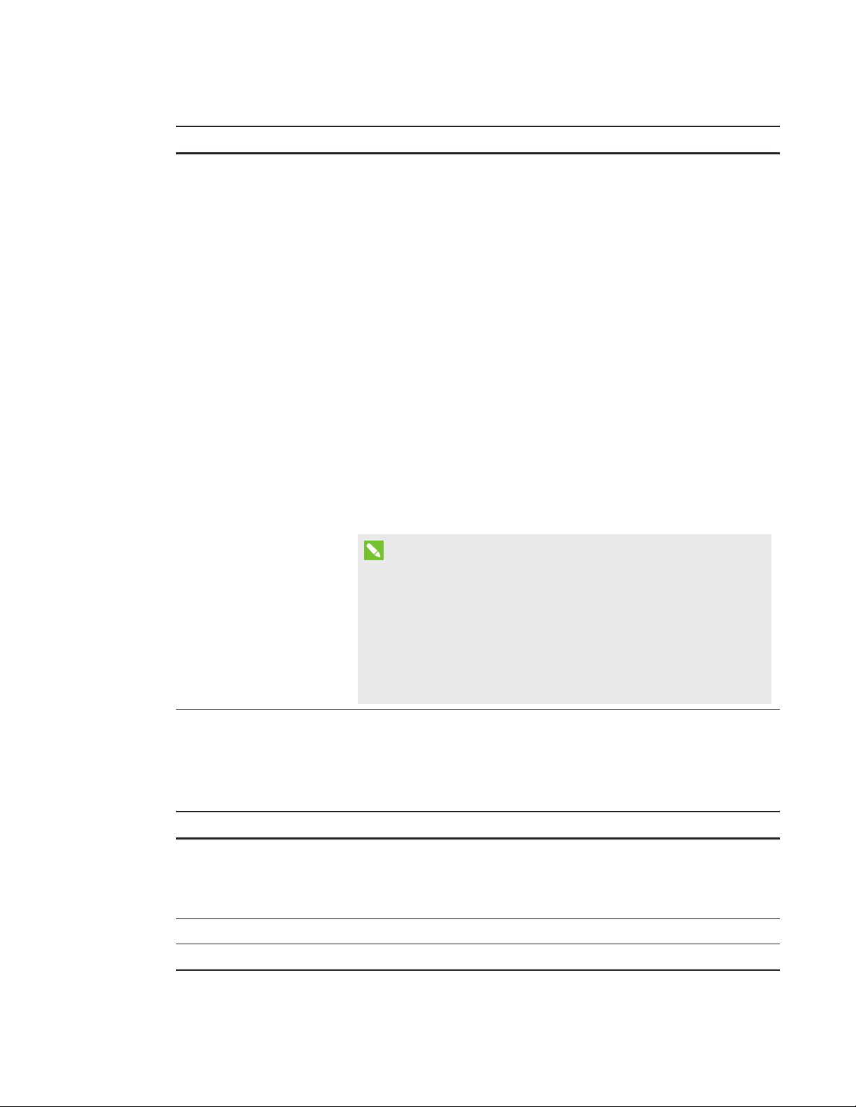
APPENDIX A
REMOTEL Y MANAGING THE SYSTEM THROUGH A N ETWORK INTERFACE
Submenu setting Descript ion
Alert Condition Sends email alerts whenever the following conditions occur. Select
the settings you want, and then click Submit.
Lamp Hours Reminder Lh
l
System Fan 1 Fail F1
l
System Fan 2 Fail F2
l
System Fan 3 Fail F3
l
Blower Fan Fail F4
l
Lamp Driver (Ballast) failure Fb
l
System Overheat OH
l
Famp Failed to Strike LF
l
Lamp voltage Too High LH
l
Color Wheel Fail FC
l
DDP (Processor Failure) FP
l
12 VDC Failure PS
l
DmD Failure Fd
l
Lamp Driver Overheat dH
l
NOTE
The projector sends an alert email (SMART Alert) to your email
address. Click Email Alert Test to confirm that your email address
and SMTP server settings are correct by sending a test email
(SMART Alert-Test Mail).
If the settings aren’t correct, the email alert messages aren’t sent
or received successfully and warnings and notification message
aren’t available to advise of this state.
Password settings
This menu provides a security function that allows an administrator to manage projector use and
enable the administrator password function.
Submenu setting Descript ion
Password When the password function is enabled, the administrator password
is required to access Web Management. Select Disable to allow
remote web management of the projector without requiring a
password.
New Password Enter a new password
Confirm Password Confirm the password
58 sm arttech.com/kb/170910
Page 67

APPENDIX A
REMOTEL Y MANAGING THE SYSTEM THROUGH A N ETWORK INTERFACE
NOTES
l The first time you enable the password settings, the default password value is four numbers,
for example, 1234.
l The maximum allowable password length is four numbers or letters.
l If you forget the projector password, refer to
Accessing the service menu
on page48 to set
the projector setting to factory defaults.
Simple Network Management Protocol (SNMP)
The projector supports a list of SNMP commands as described in the management information
base (MIB) file. You can download this file by browsing to smarttech.com/software and clicking the
MIB file’s link in the
The SNMP agent in your projector supports SNMP version 1 or 2. Upload the MIB file to your SNMP
management system application, and then use it as described in your application’s user guide.
Hardwa re
section for the projector.
59 smarttech.com/kb/170910
Page 68

Page 69

Appendix B
through an RS-232 serial interface
Serial interface settings 62
Projector programming commands 63
Projector power state controls 63
Command/response definitions 63
Field definitions 64
Source Application Selection 64
Command/response definitions 64
Field definitions 65
Video control 66
Command/response definitions 66
Field definitions 68
Audio control 71
Command/response definitions 71
Field definitions 72
Network information 74
Command/response definitions 74
Field definitions 74
System information 75
Command/response definitions 75
Field definitions 78
Service Information 83
Command/response definitions 83
Field definitions 83
Engineering commands 86
Command/response definitions 86
Field definitions 87
Additional commands 88
Command/response definitions 88
Unknown command 88
61 smarttech.com/kb/170910
Page 70

APPENDIX B
REMOTEL Y MANAGING THE SYSTEM THROUGH AN RS-232 SERIAL INTERFACE
This appendix includes detailed instructions on how to set up your computer or room control
system to remotely manage the SMARTBoard interactive whiteboard system settings through an
RS-232 serial interface.
By connecting a computer or room control system to the interactive whiteboard, you can select
video inputs, start up or shut down the interactive whiteboard system and request information such
as projector lamp use, current settings and network addresses.
Serial interface settings
The projector’s serial interface acts as a Data Communications Equipment (DCE) device, and its
settings can’t be configured. You must configure your computer’s serial communication program or
the room control system’s serial communication settings with the following values:
Sett ing Value
Data Rate 19.2 kbps
Data Bits 8
Parity None
Stop Bits 1
Flow Control None
NOTES
l Asynchronous mode is disabled by default in the projector.
l All commands should be in ASCII format. Terminate all commands with a carriage return.
l All responses from the projector are terminated with a command prompt. Wait until you
receive the command prompt indicating that the system is ready for another command
before you proceed.
l The room control feature of the projector is always on.
To configure your comput er’s serial interface
1. Turn on your computer, and then start your serial communications program or terminal
emulation program.
2. Connect your computer to the serial connection cable you previously connected to the
control panel.
62 smarttech.com/kb/170910
Page 71

APPENDIX B
REMOTEL Y MANAGING THE SYSTEM THROUGH AN RS-232 SERIAL INTERFACE
3. Configure the serial interface settings using the values from the table above, and then press
ENTER.
An “invalid cmd= ? for help” message appears, and the “>” character appears as a command
prompt on the following line.
IMPORTANT
If no message appears or if an error message appears, the serial interface configuration is
not correct. Repeat step 3.
4. Type commands to configure the settings.
NOTES
o
To see a list of commands available in the current operating mode, type ? and then
press ENTER.
o
If you’re using a terminal emulation program, turn on your program’s local echo setting
to see characters as you type them.
Projector programming commands
This section documents the projector programming commands and responses.
Projector power state controls
Use these commands to determine the projector power state and related controls.
Command/response definitions
Command Response Responds when powered off
on powerstate=[power state] yes
off [off option] powerstate=[power state] yes
get powerstate powerstate=[power state] yes
63 smarttech.com/kb/170910
Page 72

APPENDIX B
REMOTEL Y MANAGING THE SYSTEM THROUGH AN RS-232 SERIAL INTERFACE
Field definitions
Field Possible values Descript ion
off option now This is an optional field. It forces the projector
to shut down. Once this process starts, it can’t
be canceled. If “now” isn’t specified, the “off”
command causes a countdown to appear. To
turn off the projector, send a second “off”
command before the countdown expires;
otherwise the projector remains on at the end
of the countdown.
NOTE
Consider this as another projector state.
When the countdown is complete, an
asynchronous response indicates that the
projector has returned to the “on” state.
This command is accepted when the projector
has turned off, but it does nothing other than
return the power state.
powerstate
powering
l
on
l
cooling
l
confirm off
l
idle
l
The projector’s current power state. Different
projectors have different potential power
states. These power states match the power
states in the SMART U100 and SMART U100w
projectors.
Source Application Selection
Use these commands to switch among input sources and embedded applications. These
commands also control the USB switch for these sources.
Command/response definitions
Command Response Responds when powered off
set input [target] input=[current] no
get input input=[current] yes
get videoinputs videoinputs=[current] yes
set usb1source [target] usb1source=[current] yes
get usb1source usb1source=[current] yes
set usb2source [target] usb2source=[current] yes
get usb2source usb2source=[current] yes
64 smarttech.com/kb/170910
Page 73

APPENDIX B
REMOTEL Y MANAGING THE SYSTEM THROUGH AN RS-232 SERIAL INTERFACE
Field definitions
Field
current input
target input
Possible values
VGA1
l
Composite
l
HDMI1
l
HDMI2
l
None
l
= VGA1
l
= Composite
l
= HDMI1
l
= HDMI2
l
= None
l
= Next
l
current videoinputs VGA1, Composite,
HDMI1, HDMI2
current usb1source
VGA1
l
HDMI1
l
HDMI2
l
Disabled
l
Description
A text list of available video source inputs.
None is a non-selectable input and is returned
in response to a “get input” command when the
projector is turned off.
A text list of possible inputs. Selecting Next
causes the projector to move to the next item
in the list and return a response equivalent to a
user-specified input.
A comma-separated list of available projector
inputs. The strings returned in this command
must match the strings used for the input
selection from the on-screen display (OSD).
Current value for which the USB1 switch is
enabled
target usb1source
current usb2source
target usb2source
65 smarttech.com/kb/170910
= VGA1
l
= HDMI1
l
= HDMI2
l
= Disabled
l
VGA1
l
HDMI1
l
HDMI2
l
Disabled
l
= VGA1
l
= HDMI1
l
= HDMI2
l
= Disabled
l
Value to which the USB1 switch-enabled source
is set. If this value is the same as the USB2
source, the USB1 source is used and the USB2
source is ignored.
Current value of the USB2 switch
Value to which the USB2 switch-enabled
source is set. If this value is the same as the
USB2 source, the USB1 source is used and the
USB2 source is ignored.
Page 74

APPENDIX B
REMOTEL Y MANAGING THE SYSTEM THROUGH AN RS-232 SERIAL INTERFACE
EXAMPLE
> set input=vga1
input = vga1
> set input=next
input = composite
> get videoinputs
videoinputs = vga1, composite, hdmi1
> get usb1source
usb1source = vga1
> get usb2source
usb2source = hdmi1
> set usb2source=hdmi1
usb2source = hdmi1
>
Video control
Use these commands to change the projector's video output controls. The range of values used
for these commands should match the range displayed in the on-screen display (OSD). The
firmware must handle videofreeze and videomute states correctly. A change should be made to
ensure that videofreeze and videomute are mutually exclusive.
Command/response definitions
Command Response Responds when powered off
set displaymode [target] displaymode=[current] no
get displaymode displaymode=[current] no
set brightness [target] brightness=[current] no
get brightness brightness=[current] no
set contrast [target] contrast=[current] no
get contrast contrast=[current] no
set frequency [target] frequency=[current] no
get frequency frequency=[current] no
set tracking [target] tracking=[current] no
get tracking tracking=[current] no
set saturation [target] saturation=[current] no
66 smarttech.com/kb/170910
Page 75

APPENDIX B
REMOTEL Y MANAGING THE SYSTEM THROUGH AN RS-232 SERIAL INTERFACE
get saturation saturation=[current] no
set tint [target] tint=[current] no
get tint tint=[current] no
set sharpness [target] sharpness=[current] no
get sharpness sharpness=[current] no
set hposition [target] hposition=[current] no
get hposition hposition=[current] no
set vposition [target] vposition=[current] no
get vposition vposition=[current] no
set whitepeaking [target] whitepeaking=[current] no
get whitepeaking whitepeaking=[current] no
set degamma [target] degamma=[current] no
get degamma degamma=[current] no
set red [target] red=[current] no
get red red=[current] no
set green [target] green=[current] no
get green green=[current] no
set blue [target] blue=[current] no
get blue blue=[current] no
set cyan [target] cyan=[current] no
get cyan cyan=[current] no
set magenta [target] magenta=[current] no
get magenta magenta=[current] no
set yellow [target] yellow=[current] no
get yellow yellow=[current] no
set videofreeze [target] videofreeze=[current] no
get videofreeze videofreeze=[current] no
67 smar ttech.com/kb/170910
Page 76

APPENDIX B
REMOTEL Y MANAGING THE SYSTEM THROUGH AN RS-232 SERIAL INTERFACE
set displayhide displayhide= [target] no
get displayhide displayhide= [target] no
Field definitions
Field Possible values Descript ion
target displaymode
l = SMART
The ranges must match the OSD ranges.
Presentation
l = Bright room
l = Dark room
l = sRGB
l = User
current displaymode
l SMART
The ranges must match the OSD ranges.
Presentation
l Bright room
l Dark room
l sRGB
l User
target brightness
l + val
l – val
l = 0 to 100
Use + or – to change the brightness
incrementally. Enter a number within the range
to set the brightness to a specific level.
current brightness Range: 0 to 100 The device’s current brightness
target contrast
l + val
l – val
l = 0 to 100
Use + or – to change the contrast incrementally.
Enter a number within the range to set the
contrast to a specific level.
current contrast Range: 0 to 100 The device’s current contrast
target frequency
l + val
l – val
l = -5 to +5
The ranges must match the OSD ranges.
current frequency Range: -5 to +5 The ranges must match the OSD ranges.
target tracking
l + val
l – val
l = 0 to 31
The ranges must match the OSD ranges.
current tracking Range: 0 to 31 The ranges must match the OSD ranges.
68 sm arttech.com/kb/170910
Page 77

APPENDIX B
REMOTEL Y MANAGING THE SYSTEM THROUGH AN RS-232 SERIAL INTERFACE
Field Possible values Descript ion
target saturation
l + val
l – val
l = 0 to 100
The ranges must match the OSD ranges.
current saturation Range: 0 to 100 The ranges must match the OSD ranges.
target tint
l + val
l – val
l = 0 to 100
The ranges must match the OSD ranges.
current tint Range: 0 to 100 The ranges must match the OSD ranges.
target sharpness
l + val
l – val
l = 0 to 31
The ranges must match the OSD ranges.
current sharpness Range: 0 to 31 The ranges must match the OSD ranges.
target hposition
l + val
l – val
l = 0 to 100
The ranges must match the OSD ranges.
current hposition Range: 0 to 100 The ranges must match the OSD ranges.
target vposition
l + val
l – val
l = -5 to +5
The ranges must match the OSD ranges. Values
depend upon the source.
current vposition Range: -5 to +5 The ranges must match the OSD ranges.
target whitepeaking
l + val
l – val
l = 0 to 10
The ranges must match the OSD ranges.
current whitepeaking Range: 0 to 10 The ranges must match the OSD ranges.
target degamma
l + val
l – val
l = 0 to 3
The ranges must match the OSD ranges.
current degamma Range: 0 to 3 The ranges must match the OSD ranges.
target red
l + val
l – val
l = 0 to 100
The ranges must match the OSD ranges.
current red Range: 0 to 100 The ranges must match the OSD ranges.
69 smarttech.com/kb/170910
Page 78

APPENDIX B
REMOTEL Y MANAGING THE SYSTEM THROUGH AN RS-232 SERIAL INTERFACE
Field Possible values Descript ion
target green
l + val
l – val
l = 0 to 100
The ranges must match the OSD ranges.
current green Range: 0 to 100 The ranges must match the OSD ranges.
target blue
l + val
l – val
l = 0 to 100
The ranges must match the OSD ranges.
current blue Range: 0 to 100 The ranges must match the OSD ranges.
target cyan
l + val
l – val
l = 0 to 100
The ranges must match the OSD ranges.
current cyan Range: 0 to 100 The ranges must match the OSD ranges.
target magenta
l + val
l – val
l = 0 to 100
The ranges must match the OSD ranges.
current magenta Range: 0 to 100 The ranges must match the OSD ranges.
target yellow
l + val
l – val
l = 0 to 100
The ranges must match the OSD ranges.
current yellow Range: 0 to100 The ranges must match the OSD ranges.
target videofreeze
current videofreeze
current displayhide
target displayhide
70 smarttech.com/kb/170910
l = on
l = off
l = on
l = off
l normal
l frozen
l muted
l normal
l frozen
l muted
l next
Video freeze on/off
Video freeze on/off
Matches the three states of the Hide button on
the remote control.
Set the mode directly or move from one state
to the next sequentially.
Page 79

APPENDIX B
REMOTEL Y MANAGING THE SYSTEM THROUGH AN RS-232 SERIAL INTERFACE
Use the above commands to set the property to an absolute value or to adjust the current value.
EXAMPLE
>get brightness
brightness=55
>set brightness = 65
brightness=65
>set brightness +5
brightness=70
>set brightness -15
brightness=55
>
All video commands also have an optional source specification. For example, to set the brightness
of a specific source, use the following command.
EXAMPLE
>set brightness = 65
brightness=65
>set brightness vga1 = 65
brightness vga1 = 65
This sets the brightness of the VGA1 source whether the projector is on this source or not.
Audio control
Use these commands to set audio output controls. The range of values used for these commands
should match the range shown in the on-screen display (OSD).
Command/response definitions
Command Response Powered off
set volume [target] volume=[current] no
get volume volume=[current] no
set micvolume [target] micvolume=[current] no
get micvolume micvolume=[current] no
set mute [target] mute=[current] no
get mute mute=[current] no
71 smar ttech.com/kb/170910
Page 80

APPENDIX B
REMOTEL Y MANAGING THE SYSTEM THROUGH AN RS-232 SERIAL INTERFACE
Command Response Powered off
set volumecontrol
[target]
get volumecontrol volumecontrol=
volumecontrol=
[current]
no
no
[current]
set cc [target] cc=[current] no
get cc cc=[current] no
set sysoutputsw
sysoutputsw=[current] no
[target]
get sysoutputsw sysoutputsw=[current] no
Field definitions
Field Possible values Descript ion
target volume l + val
l – val
l = -20 to 20
Use + or – to change the volume incrementally.
Enter a number within the range to set the
volume to a specific level. When you modify
the volume using the RS-232, the OSD's
volume slider matches the slider that appears
when you use another control. Note that -20
should map to 0 and 20 should map to 40.
current volume
Range: -20 to 20
target micvolume l + val
l – val
l = -20 to 20
current micvolume
Range: -20 to 20
target mute l = on
l = off
current mute l = on
l = off
The device’s current volume. Note that -20
should map to 0 and 20 should map to 40.
Use + or – to change the micvolume
incrementally. Enter a number within the range
to set the volume to a specific level. When you
modify the volume using the RS-232, the OSD's
volume slider matches the slider that appears
when you use another control. Note that -20
should map to 0 and 20 should map to 40.
The device’s current volume.
Specifies whether mute is enabled or disabled.
Current state of the mute function
72 smar ttech.com/kb/170910
Page 81

APPENDIX B
REMOTEL Y MANAGING THE SYSTEM THROUGH AN RS-232 SERIAL INTERFACE
Field Possible values Descript ion
current volumecontrol l = on
l = off
target volumecontrol l = on
l = off
target cc l = cc1
l = cc2
l = off
current cc l = cc1
l = cc2
l = off
target sysoutputsw l = line+spkr
l = line
l = spkr
l = none
current sysoutputsw l = line+spkr
l = line
l = spkr
l = none
Current state of the volume control
Specifies whether volume control is enabled or
disabled.
Closed captioning states
Closed captioning states
Specifies the system output switch
Current state of the system output switch
Use the commands above to set the property to an absolute value or to adjust the current value.
EXAMPLE
>get volume
volume=0
>set volume=-10
volume=-10
>set volume +5
volume=-5
>set volume -15
volume=-20
73 smarttech.com/kb/170910
Page 82

APPENDIX B
REMOTEL Y MANAGING THE SYSTEM THROUGH AN RS-232 SERIAL INTERFACE
Network information
Use these commands to set your network information.
Command/response definitions
Command Response Powered off
get netstatus netstatus=[current] yes
set network network=[current] yes
get network network=[current] yes
set dhcp [target] dhcp=[current] yes
get dhcp dhcp=[current] yes
set ipaddr [target] ipaddr=[current] yes
get ipaddr ipaddr=[current] yes
set subnetmask
subnetmask=[current] yes
[target]
get subnetmask subnetmask=[current] yes
set gateway [target] gateway=[current] yes
get gateway gateway=[current] yes
set primarydns [target] primarydns=[current] yes
get primarydns primarydns=[current] yes
get macaddr macaddr=[MAC
yes
address]
Field definitions
Field Possible values Descript ion
current netstatus l connected
l disconnected
current network l on
l off
Current status of the network interface
Current status of the network module and the
VGA output
target network l on
l off
74 smarttech.com/kb/170910
Enable/Disable network module and VGA
output
Page 83

APPENDIX B
REMOTEL Y MANAGING THE SYSTEM THROUGH AN RS-232 SERIAL INTERFACE
Field Possible values Descript ion
current dhcp l = on
l = off
target dhcp l on
l off
current ipaddr
Range: 0.0.0.0 to
255.255.255.255
target ipaddr
= Range: 0.0.0.0 to
255.255.255.255
current subnetmask
Range: 0.0.0.0 to
255.255.255.255
target subnetmask
= Range: 0.0.0.0 to
255.255.255.255
current gateway
Range: 0.0.0.0 to
255.255.255.255
target gateway
= Range: 0.0.0.0 to
255.255.255.255
current primarydns
Range: 0.0.0.0 to
255.255.255.255
Enable/Disable for DHCP Networking
Enable/Disable for DHCP Networking
Current IP address (static or dhcp assigned)
Set to static IP Address
Current subnet Mask
Target subnet Mask
Current gateway
Target gateway
Current primary dns
target primarydns
= Range: 0.0.0.0 to
Target primary dns
255.255.255.255
MAC address
xx-xx-xx-xx-xx-xx
The device’s MAC address.
System information
Use these commands to set the system information.
Command/response definitions
Command Response Powered off
set autosignal [target] autosignal=[current] no
get autosignal autosignal=[current] no
set lampreminder
[target]
get lampreminder lampreminder=
lampreminder=
[current]
[current]
no
no
75 smar ttech.com/kb/170910
Page 84

APPENDIX B
REMOTEL Y MANAGING THE SYSTEM THROUGH AN RS-232 SERIAL INTERFACE
Command Response Powered off
set lampmode [target] lampmode=[current] no
get lampmode lampmode=[current] no
set ImageCare [target] ImageCare=[current] no
get ImageCare ImageCare=[current] no
set autopoweroff
autopoweroff=[current] no
[target]
get autopoweroff set
autopoweroff=[current] no
zoom [target]
set zoom [target] zoom=[current] no
get zoom zoom=[current] no
set projectorid [target] projectorid=[current] no
get projectorid projectorid=[current] no
set aspectratio [target] aspectratio=[current] no
get aspectratio aspectratio=[current] no
set projectionmode
[target]
get projectionmode projectionmode=
projectionmode=
[current]
no
no
[current]
set startupscreen
startupscreen=[current] no
[target]
get startupscreen startupscreen=[current] no
set restoredefaults restoredefaults=
yes
[current]
get lamphrs lamphrs=[current] yes
set lamphrs [target] lamphrs=0 yes
get syshrs syshrs=[current] yes
get resolution resolution=[current] no
get nativeaspectratio nativeaspect=[native] no
get fwverddp fwverddp=[current] yes
get fwvernet fwvernet=[current] yes
get fwvermpu fwvermpu=[current] yes
76 smar ttech.com/kb/170910
Page 85

APPENDIX B
REMOTEL Y MANAGING THE SYSTEM THROUGH AN RS-232 SERIAL INTERFACE
Command Response Powered off
get serialnum serialnum=[current] yes
get fwverecp fwverecp=[current] yes
set language [target] language=[current] no
get language language=[current] no
set groupname [target] groupname=[current] no
get groupname groupname=[current] no
set projectorname
[target]
get projectorname projectorname=
projectorname=
[current]
no
no
[current]
set locationinfo [target] locationinfo=[current] no
get locationinfo locationinfo=[current] no
set contactinfo [target] contactinfo=[current] no
get contactinfo contactinfo=[current] no
get modelnum modelnum=U100, or
modelnum=U100w
no
Returns the actual model of the projector
set videomute [target] videomute=[current] no
get videomute videomute=[current] no
set vgaoutnetenable
[target]
get vgaoutnetenable vgaoutnetenable=
vgaoutnetenable=
[current]
yes
yes
[current]
set
emergencyalertmsg
emergencyalertmsg=
[current]
no
[target]
get
emergencyalertmsg
set emergencyalert
[target]
emergencyalertmsg=
[current]
emergencyalert=
[current]
get emergencyalert emergencyalert=
[current]
get signaldetected signaldetected=
[current]
77 sm arttech.com/kb/170910
no
no
no
yes
The response varies depending on the power
mode.
Page 86

APPENDIX B
REMOTEL Y MANAGING THE SYSTEM THROUGH AN RS-232 SERIAL INTERFACE
Field definitions
Field Possible values Descript ion
target autosignal
current autosignal
target lampreminder
current lampreminder
target lampmode
current lampmode
target ImageCare
current ImageCare
= on
l
= off
l
on
l
off
l
= on
l
= off
l
on
l
off
l
= standard
l
= ECO
l
standard
l
ECO
l
= on
l
= off
l
on
l
off
l
The ranges must match the OSD settings.
The ranges must match the OSD settings.
The ranges must match the OSD settings.
The ranges must match the OSD settings.
The ranges must match the OSD settings.
The ranges must match the OSD settings.
The ranges must match the OSD settings.
The ranges must match the OSD settings.
target autopoweroff
current autopoweroff
target zoom
current zoom
target projectorid
+ val
l
– val
l
= 0 to 240
l
+ val
l
– val
l
= 0 to 240
l
+ val
l
– val
l
= 0 to 30
l
= 0 to 30 The ranges must match the OSD ranges.
l
+ val
l
– val
l
= 0 to 999
l
The ranges must match the OSD ranges.
The ranges must match the OSD ranges.
The ranges must match the OSD ranges.
The ranges must match the OSD ranges.
78 smar ttech.com/kb/170910
Page 87

APPENDIX B
REMOTEL Y MANAGING THE SYSTEM THROUGH AN RS-232 SERIAL INTERFACE
Field Possible values Descript ion
current projectorid
target aspectratio
current aspectratio
= 0 to 999 The ranges must match the OSD ranges.
l
= fill
l
= match
l
= 16:9
l
The ranges must match the OSD ranges.
Fill:
Regardless of the input, the image is stretched
to match the DMD device. For example, a 16:9
image appears as a 4:3 image on an XGA
projector and as a 16:10 image on a WXGA
projector.
Match:
The signal is scaled so that the input aspect
ratio is maintained. For example, a 4:3 image
appears as a 4:3 image on screen.
16:9
The signal is scaled and stretched to produce a
16:9 image.
l
l
l
fill
match
16:9
The ranges must match the OSD settings.
target projectionmode
current
projectionmode
target startupscreen
current startupscreen
= front
l
= ceiling
l
= rear
l
= rear ceiling
l
= front
l
= ceiling
l
= rear
l
= rear ceiling
l
= smart
l
= usercapture
l
= preview
l
= smart
l
= usercapture
l
= preview
l
The ranges must match the OSD settings.
The ranges must match the OSD settings.
The ranges must match the OSD settings.
The ranges must match the OSD settings.
79 smar ttech.com/kb/170910
Page 88

APPENDIX B
REMOTEL Y MANAGING THE SYSTEM THROUGH AN RS-232 SERIAL INTERFACE
Field Possible values Descript ion
current reset
current lamphrs
done Sent once you reset the projector.
l
0 to 5000 Current lamp hour usage
l
target lamphrs 0 Clear the current lamp hour usage. The only
valid value is 0.
current resolution
native aspect ratio 4:3 for SMART U100,
800x600
l
1024x768
l
…
l
no signal
l
16:10 for SMART
U100w
Current resolution of the input. If no signal is
detected, “resolution=no signal” appears.
Native aspect ratio. DLP resolution of the
projector. Returns the actual native aspect ratio
of the projector.
current fwverddp x.x.x.x Firmware version
current fwvernet x.x.x.x Network processor version
current fwvermpu x.x.x.x MPU version
current prjserialnum xxxxxxxxxxxxx Projector serial number
current fwverecp x.x.x.x ECP version, if present
80 smarttech.com/kb/170910
Page 89

APPENDIX B
REMOTEL Y MANAGING THE SYSTEM THROUGH AN RS-232 SERIAL INTERFACE
Field Possible values Descript ion
current language
English (US)
l
English (U.K.)
l
French (France)
l
German
l
Dutch
l
Danish
l
Finnish
l
Italian
l
Norwegian
l
Russian
l
Spanish
l
Swedish
l
Portugese
l
Chinese
l
(Simplified)
Chinese
l
(Traditional)
Czech
l
Hungarian
l
Japanese
l
Malayasian
l
Polish
l
Romanian
l
Arabic
l
Turkish
l
Greek
l
Slovak
l
Korean
l
Hebrew
l
Must match the OSD setting
target language = above Must match the OSD setting.
target groupname = user string
current groupname user string
target projectorname = user string
81 smarttech.com/kb/170910
Page 90

APPENDIX B
REMOTEL Y MANAGING THE SYSTEM THROUGH AN RS-232 SERIAL INTERFACE
Field Possible values Descript ion
current projectorname user string
target locationinfo = user string
current locationinfo user string
target contactinfo = user string
current contactinfo user string
current modelnum user string Must match the OSD setting
current videomute
target videomute
current
vgaoutnetenable
target
vgaoutnetenable
current
emergencyalertmsg
target
emergencyalertmsg
current
emergencyalert
target
emergencyalertmsg
l
l
l
l
l
l
l
l
on
off
= on
= off
on
off
= on
= off
Must match the OSD setting.
Must match the OSD setting.
Status of VGA Out Enable and Network Enable
Value for VGA Out and Network Enable
User string Emergency Alert message
= User string Set the Emergency Alert message
l
l
l
l
on
off
= on
= off
To display the alert message, set this value to
“on.”
If the message is being displayed, “on” is
returned.
current signaldetected
l
l
true
false
If a signal is detected, “true” is returned.
Command List .... A list of commands appears. This list doesn’t
include service information commands.
82 sm arttech.com/kb/170910
Page 91

APPENDIX B
REMOTEL Y MANAGING THE SYSTEM THROUGH AN RS-232 SERIAL INTERFACE
Service Information
These commands are used in servicing and manufacturing the projector. They are hidden from the
user during normal operation.
Command/response definitions
Command Response Powered off
get displayhour displayhour=[current] no
set testpattern [target] testpattern=[current] no
set colorwheelidx
[target]
get colorwheelidx colorwheelidx=
colorwheelidx=
[current]
no
no
[current]
get failurelog failurelog=[current] yes
get error# error#=[current] yes
set factoryreset
factoryreset=[current] yes
[target]
set highspeedfan
[target]
get highspeedfan highspeedfan=
highspeedfan=
[current]
no
no
[current]
set statereporting
[target]
get statereporting statereporting=
statereporting=
[current]
yes
yes
[current]
get poweroverride poweroverride=
no
[current]
set poweroverride
[target]
poweroverride=
[current]
no
Field definitions
Field
Possible Values
Description
current displayhour 0 to 20000 Current display hours.
target testpattern = 1 to 4 Set the test pattern to pattern number (1 to 4). If
there’s only one test pattern, call it test
pattern1.
83 smarttech.com/kb/170910
Page 92

APPENDIX B
REMOTEL Y MANAGING THE SYSTEM THROUGH AN RS-232 SERIAL INTERFACE
Field
current testpattern
Possible Values
1: 19 × 25 Grid
l
2: Red
l
3: Green
l
4: Blue
l
5: Grey
l
6: White
l
l 7: Black
Description
Test pattern being displayed. The built-in test
pattern can be changed.
target colorwheelidx = ??? The ranges must match the OSD ranges.
current colorwheelidx ??? The ranges must match the OSD ranges.
84 smarttech.com/kb/170910
Page 93

APPENDIX B
REMOTEL Y MANAGING THE SYSTEM THROUGH AN RS-232 SERIAL INTERFACE
Field
current failurelog
Possible Values
Normal (NO)
l
Lamp Failed to
l
Strike (LS)
Lamp Failed (LF)
l
Lamp Hours
l
Reminder (Lh)
Lamp Voltage
l
Too High (LH)
System Fan 1 Fail
l
(F1)
System Fan 2 Fail
l
(F2)
System Fan 3 Fail
l
(F3)
Rear Blower Fan
l
Fail (F4)
Front Blower Fan
l
Fail (F5)
Colour Wheel Fail
l
(FC)
12 VDC Failure
l
(PS)
DDP Processor
l
Failure (FP)
DmD Failure (Fd)
l
Lamp Driver
l
failure (Fb)
Lamp Driver
l
Overheat (dH)
System Overheat
l
(OH)
Description
Projector's error state. The modes are projector
dependent.
When get failurelog is used, the abbreviated
version of the error state (in parenthesis) is
retrieved.
When get error# is used, the full name of the
error is retrieved.
Current error# Provide the details of
the specific error. “#”
is the number
recorded in the log. It
ranges from 1 to 5. 1
indicates the most
recent error and 5
indicates the oldest
error.
85 sm arttech.com/kb/170910
The details include the failure reason, system
hours, lamp hours, sensor temperature and
lamp voltage.
Example:
error1=Rear Blower Fan Fail F4, syshrs:1000,
lamphrs=1000, temp=60,volt=120.
error2= System Overheat OH, syshrs:3000,
lamphrs=2900, temp=150,volt=120.
Page 94

APPENDIX B
REMOTEL Y MANAGING THE SYSTEM THROUGH AN RS-232 SERIAL INTERFACE
Field
target factoryreset
current factoryreset
target highspeedfan
current highspeedfan
current statereporting
target statereporting
current poweroverride
Possible Values
= true
l
= false
l
= true
l
= false
l
= high
l
= normal
l
high
l
normal
l
on
l
off
l
= on
l
= off
l
on
l
off
l
Description
If set to “true,” perform a factory reset.
Otherwise, do nothing.
Set to “true” only if a factory reset is about to
occur.
Must match the OSD settings.
Must match the OSD settings.
Current state reporting value
Target state reporting value
A power override forces the projector to
remain on when the command is received. This
command isn’t persistent and isn’t stored to
non-volatile memory (cleared on power cycle).
When this mode is enabled, the power button
on the remote control and the ECP, if present,
must not turn off the projector.
This command must also be added to the
service menu so the user can disable it from the
OSD.
target poweroverride
l
l
= on
= off
Sets the power override
Engineering commands
These commands are to be part of the RS232 list but not viewable by the “?” command
Command/response definitions
Command Response Powered off
set dbmsgon [target] dbmsgon =[current] no
86 sm arttech.com/kb/170910
Page 95

APPENDIX B
REMOTEL Y MANAGING THE SYSTEM THROUGH AN RS-232 SERIAL INTERFACE
Command Response Powered off
get vgacalibration vgacalibration =
no
[current]
get waveformid waveformid=[current] no
get lampvoltage lampvoltage =[current] no
get temperature temperature =[current] no
set temperaturereport
[target]
set
downloadlampdriver
temperaturereport=
[current]
downloadlampdriver=
[current]
no
no
[target]
clearfailurelog no
set burnin no
dwscaler#7537 no
Field definitions
Field
target dbmsg
Possible Values
on
l
off
l
Description
Turn on/off debug message.
current vgacalibration
??? To get the status of ADC calibration while
l
power on.
current waveformid
current lampvoltage
current temperature
target
temperaturereport
target
??? To get waveform ID while power on.
l
??? To get lamp voltage while power on.
l
??? To get system temperature while power on.
l
on
l
off
l
done Auto program waveform while standby
l
While set to on, the system temperature is sent
every five seconds (requires high-speed fan
mode to be on)
downloadlampdriver
clearfailurelog
done Clear all failure log for production burn in
l
preparation.
dwscaler#7537 Enter DDP download mode
87 smar ttech.com/kb/170910
Page 96

APPENDIX B
REMOTEL Y MANAGING THE SYSTEM THROUGH AN RS-232 SERIAL INTERFACE
Additional commands
These commands and behaviors are to provide backward compatibility for legacy control
interfaces.
Command/response definitions
Command Execut e command: Behaviour
set input=VGA1 set input=VGA1 switch to VGA1 port
set input=Composite set input=NEXT switch to next physical port
set input=HDMI1 set input=NEXT switch to next physical port
set input=HDMI2 set input=NEXT switch to next physical port
Unknown command
If an unknown command is received, the projector sends the following response to the user (there
is a space between “invalid” and “cmd”).
>dummycommand 2134
invalid cmd=dummycommand 2134
88 smarttech.com/kb/170910
Page 97

Appendix C
Video format 89
Native Video Format 89
Video format compatibility 90
SMARTU100 projector 90
SMARTU100w projector 91
HD and SD signal format compatibility 93
SMARTU100 projector 93
SMARTU100w projector 93
Video system signal compatibility 94
SMARTU100 projector 94
SMARTU100w projector 94
Connecting peripheral sources and outputs 95
This appendix provides information on integrating the SMARTBoard interactive whiteboard
system with peripheral devices.
Video format
The projector has a native video format and various video format compatibility modes. You can
change image appearances for certain formats and compatibilities.
Native Video Format
The following table lists the native VESA RGB video formats for the projector.
Projector Resolut ion Mode Aspect ratio Refresh
rat e
(Hz)
SMART U100 1024 × 768 XGA 4:3 60 48 65
SMART U100w 1280 × 800 WXGA 16:10 60 48 65
89 sm arttech.com/kb/170910
Hor izontal
frequency
(kHz)
Pixel
clock
(MHz)
Page 98

APPENDIX C
INTEGRATING OTHER DEVICES
Video format compatibility
The following tables list the projectors’ compatible VESA RGB video formats by resolution, which
the projector adjusts automatically when you use the aspect ratio commands described in
Adjusting projector settings
SMAR TU100 project or
Resolution Mode Aspect ratio Refresh rat e (Hz) Mat ch In pu t
720 × 400 720×400_85 1.8:1 85.039 Letterbox
640 × 480 VGA 60 4:3 59.94 Full screen
640 × 480 VGA 72 4:3 72.809 Full screen
640 × 480 VGA 75 4:3 75 Full screen
640 × 480 VGA 85 4:3 85.008 Full screen
800 × 600 SVGA 56 4:3 56.25 Full screen
on page12.
appearance
800 × 600 SVGA 60 4:3 60.317 Full screen
800 × 600 SVGA 72 4:3 72.188 Full screen
800 × 600 SVGA 75 4:3 75 Full screen
800 × 600 SVGA 85 4:3 85.061 Full screen
832 × 624 MAC 16" 4:3 74.55 Full screen
1024 × 768 XGA 60 4:3 60.004 Full screen
1024 × 768 XGA 70 4:3 70.069 Full screen
1024 × 768 XGA 75 4:3 75.029 Full screen
1024 × 768 XGA 85 4:3 84.997 Full screen
1024 × 768 MAC 19" 4:3 74.7 Full screen
1152 × 864 SXGA1 75 4:3 75 Full screen
1280 × 720 HD 720 16:9 60 Letterbox
1280 × 768 SXGA1 75 1.67:1 60 Letterbox
1280 × 800 WXGA 16:10 60 Letterbox
1280 × 960 Quad VGA 60 4:3 60 Full screen
1280 × 960 Quad VGA 85 4:3 85.002 Full screen
1280 × 1024 SXGA3 60 5:4 60.02 Letterbox
1280 × 1024 SXGA3 75 5:4 75.025 Letterbox
90 smarttech.com/kb/170910
Page 99

APPENDIX C
INTEGRATING OTHER DEVICES
Resolution Mode Aspect ratio Refresh rat e (Hz) Mat ch In pu t
appearance
1280 × 1024 SXGA3 85 5:4 85.024 Letterbox
1360 × 765 1.04M9 16:9 59.799 Letterbox
1600 × 900 1.44M9 16:9 59.946 Letterbox
1600 × 1200 UXGA 4:3 60 Full screen
1680 × 1050 1680x1050 50 16:10 49.974 Letterbox
1680 × 1050 1680x1050 50 16:10 59.954 Letterbox
1920 × 1080 HD 1080 16:9 60 Letterbox
SMAR TU100w project or
Resolution Mode Aspect
rat io
Refresh
rat e (Hz)
Match Input
appearance
(16:10 aspect
rat io mode)
Match Input
appearance
(16:9 aspect
rat io mode)
720 × 400 720×400_85 9:5 85.039 Letterbox Letterbox
640 × 480 VGA 60 4:3 59.94 Pillarbox Pillarbox
800 × 600 VGA 72 4:3 72.809 Pillarbox Pillarbox
800 × 600 VGA 75 4:3 75 Pillarbox Pillarbox
800 × 600 VGA 85 4:3 85.008 Pillarbox Pillarbox
800 × 600 SVGA 56 4:3 56.25 Pillarbox Pillarbox
800 × 600 SVGA 60 4:3 60.317 Pillarbox Pillarbox
800 × 600 SVGA 72 4:3 72.188 Pillarbox Pillarbox
800 × 600 SVGA 75 4:3 75 Pillarbox Pillarbox
800 × 600 SVGA 85 4:3 85.061 Pillarbox Pillarbox
832 × 624 MAC 16" 4:3 74.55 Pillarbox Pillarbox
1024 × 768 XGA 60 4:3 60.004 Pillarbox Pillarbox
1024 × 768 XGA 70 4:3 70.069 Pillarbox Pillarbox
1024 × 768 XGA 75 4:3 75.029 Pillarbox Pillarbox
1024 × 768 XGA 85 4:3 84.997 Pillarbox Pillarbox
1024 × 768 MAC 19" 4:3 74.7 Pillarbox Pillarbox
91 smarttech.com/kb/170910
Page 100

APPENDIX C
INTEGRATING OTHER DEVICES
Resolution Mode Aspect
rat io
Refresh
rat e (Hz)
Match Input
appearance
(16:10 aspect
rat io mode)
Match Input
appearance
(16:9 aspect
rat io mode)
1152 × 864 SXGA 75 4:3 75 Pillarbox Pillarbox
1280 × 768 WXGA 60 1.67:1 60 Letterbox Pillarbox
1280 × 960 Quad VGA 60 4:3 60 Pillarbox Pillarbox
1280 × 960 Quad VGA 85 4:3 85.002 Pillarbox Pillarbox
1280 × 960 SXGA3 60 5:4 60.02 Pillarbox Pillarbox
1280 × 1024 SXGA3 75 5:4 75.025 Pillarbox Pillarbox
1600 × 1200 SXGA+ 4:3 59.978 Pillarbox Pillarbox
1600 × 1200 UXGA_60 4:3 60 Pillarbox Pillarbox
92 smarttech.com/kb/170910
 Loading...