

Page 1
Operating instructions
smart fortwo coupé and smart fortwo cabrio
Page 2

Page 3

>>Let the fun begin!
Congratulations on choosing the smart fortwo coupé or smart fortwo cabrio. We're pleased about your decision. No doubt you are also
full of anticipation and want to finally start driving your car.
We'll show you what it's all about, give you a few important pieces of advice and some tips.
Please study these operating instructions thoroughly to ensure that you have more enjoyment with your smart and can recognise and
avoid any potential dangers to yourself or others.
The Operating Instructions, Quick Guide, Service Booklet and list of smart centers constitute part of the car itself. You should always
keep these documents in the car and make sure that you pass them on to the next owner if and when you come to sell your smart.
Incidentally, smart is among the first automotive manufacturers to offer a soot filter in the compact car segment. The maintenance
free system considerably reduces the hazardous soot particles emitted by the smart cdi engine. This contributes to environmental pro
tection and human health.
Page 4

Contents
>>Let the fun begin!
Introduction............................................. 4
>>Blind date.
Unlocking and locking............................ 10
Adjusting the seats................................ 17
Mirrors, adjustment .............................. 22
Power windows ....................................... 24
Seat belts ............................................... 25
Belt tensioners and belt force limiters 29
Cockpit, lefthand drive model ............. 31
Cockpit, righthand drive model........... 32
Control levers........................................ 33
Instrument cluster,
lefthand drive model............................ 34
Instrument cluster,
righthand drive model ......................... 35
Instrument cluster ................................ 36
Upper centre console............................ 51
Lower centre console ........................... 55
Shift lever console ................................ 56
All sections marked with the * symbol refer to either factoryfitted optional extras or original smart accessories.
>>Light conditions.
Lights .....................................................58
Headlight range control.........................61
Interior lights ........................................62
Fog lamps ...............................................63
Turn signal lights...................................65
Warning sounds and indicator lights.....66
>>Communication.
Audio/telematics devices*.....................68
smart radio one*....................................69
smart radio three*.................................70
smart radio five*....................................71
smart radio navigator* ..........................72
smart CD changer*.................................76
CD box*...................................................77
Cassette box*.........................................80
Telephone console*................................83
Universal handsfree system*............... 86
ipod*.......................................................87
smart sound package* ...........................88
>>Weather outlook.
Sun visors .............................................. 90
Sunroof visor* ....................................... 92
Power glass sliding roof* ...................... 93
Coat hooks ............................................. 95
Heater/ventilation ................................. 96
Air conditioning plus* ......................... 102
Wipers .................................................. 105
Rear window heater ............................. 107
Outside mirror heaters* ..................... 108
Seat heater*......................................... 109
Car cover* ........................................... 110
>>Variable driving enjoyment.
Soft top system (only smart cabrio).... 112
Windblocker* ....................................... 120
Notes on the soft top system............... 122
Soft top system faults.......................... 123
Care notes and maintenance ............... 125
>>Child friendly.
Child restraint systems* ..................... 130
Using child restraint systems* ........... 133
2 Good news
Page 5

Contents
>>Study in motion.
Before driving off................................ 136
Driving ................................................. 139
Parking................................................. 147
Driving in winter.................................. 149
Driving with a catalytic converter ...... 151
Driving tips.......................................... 152
Cruise control*.................................... 154
Speed limiter*...................................... 157
Brakes.................................................. 160
Electronic Stability Program (esp)...... 165
Airbags ................................................ 166
>>Loading up.
Storage compartments and trays........ 174
Luggage compartment......................... 183
Luggage compartment cover*............. 188
Luggage net bag* ................................ 190
Divider* between the luggage and
passenger compartments (coupé)....... 193
Divider* between the luggage and
passenger compartments (cabrio)...... 195
Multifunction box* ............................... 197
Rear rack* ........................................... 198
Loading guidelines .............................. 199
All sections marked with the * symbol refer to either factoryfitted optional extras or original smart accessories.
>>Parttime jobs.
Refuelling .............................................204
Oil level ................................................206
Checking operating fluids ...................210
Tyre inflation pressure .......................215
Wiper blades.........................................218
Care notes............................................219
>>Communications breakdown.
Onboard diagnosis socket (OBD) ....... 226
Fuses ....................................................227
Bulbs.....................................................232
12volt power socket...........................235
Breakdown set* ....................................236
Wheel trim cap* .................................... 242
Wheel theft protection* .......................243
Tyres and wheels .................................244
Battery .................................................252
Roll starting .........................................259
Towing ..................................................260
Fire extinguisher* ...............................263
>>Data transfer.
Information signs
(example: lefthand drive version) ..... 266
Model plate .......................................... 267
Technical data ..................................... 268
Homologation numbers ........................ 278
Official homologation........................... 279
>>Key word index.
Good news 3
Page 6

Introduction
Introduction
The concept of these operating
instructions
Driving a vehicle is just one of its fac
ets; discovering a vehicle in detail is
all about gaining an insight into its in
credibly broad scope.
At the start of every chapter we tell you
precisely what awaits you, and perhaps a
little more too.
To help you find your way around with
even greater ease, each chapter is co
lourcoded.
Here is a brief overview:
>>Blind date.
> For an initial impression.
>>Light conditions.
> All about the lights.
>>Communication.
> Radios, telephones and all other en
tertainment features.
>>Weather outlook.
> Preparing you for all types of weath
er.
>>Variable driving enjoyment.
> Roof features and more.
>>Child friendly.
> Carrying children safely and cor
rectly.
>>Study in motion.
> Driving and everything that it in
volves.
>>Loading up.
> How best to load the car and stow
items.
>>Parttime jobs.
> Refuelling, checking and topping
up.
>>Communications breakdown.
> Performing minor repairs swiftly
and effectively.
>>Data transfer.
> The technical data.
4 Good news
Page 7
Introduction
Clarity is our aim
Fewer words can often say more. To help
you enjoy reading these texts and concen
trate on what really matters, we have in
corporated a variety of design elements
that we'd like to outline here:
Lists
Items in lists are always preceded by a
dash:
to keep the list clearer,
for ease of recognition and under
standing.
When you need to act
In this instance, first of all we inform
you what you need to do, then provide any
supplementary information that is nec
essary.
In other words:
쮿 Ensure that you read through these de
tailed operating instructions
> only then will you be able to handle
your vehicle expertly and recognise
and avoid hazards both to yourself
and to others.
Notes
>Note!
Notes provide supplementary informa
tion on a topic.
>Important!
Anything that could result in material
damage is classified as important.
Safety notes
Safety instructions draw your attention
to potential hazards that could damage
your health or even have fatal conse
quences.
Danger of injury!
We want to protect you, other oc
cupants and other road users as effec
tively as possible.
For this reason, it is essential to read
and observe the sections marked with
this symbol.
Good news 5
Page 8

Introduction
Protection of the environment
The environmental policy of smart gmbh
is based on the environmental guidelines
of DaimlerChrysler, which are imple
mented in every phase of the product's
life. Protecting the environment, saving
energy and preserving natural resources
are essential components of all princi
ples. This starts with vehicle develop
ment, encompasses the production
process and ends with the recycling of
many different components.
Returning used vehicles
You can return your smart fortwo coupé or
smart fortwo cabrio to us for environ
mentally friendly disposal in accordance
with the EU Directive on End of Life Ve
hicle Law
1
but that day lies a long way
off.
About these operating instructions
As the scope of delivery of your vehicle
depends on the order placed, the equip
ment in it may deviate from that shown in
some of the descriptions and illustra
tions. In order to adapt our vehicles to
the everadvancing technologies avail
able, we must reserve the right to make
changes to design, equipment and tech
nology.
Therefore no claims can be derived from
any of the specifications, illustrations
or descriptions in these operating in
structions.
Environment!
We want to protect our environ
ment.
For this reason, it is essential to read
the sections marked with this symbol.
1 Applies in accordance with the national statutory provisions for motor vehicles. The smart fortwo coupé and the smart fortwo cabrio have fulfilled legal requirements for
recyclable design for some years now. A network of collection points and disassembly workshops is available to receive endoflife vehicles, where your vehicle can be
recycled in an environmentallyfriendly manner. At the same time, the possibilities for the recycling of vehicles and vehicle parts are continually being developed and
improved, The smart fortwo coupé and the smart fortwo cabrio consequently will remain able to meet the higher statutory recycling quotas that will take effect in the future.
Visit www.smart.com for more information.
6 Good news
Page 9

Introduction
Accessories and optional extras
All texts marked with an asterisk * refer
either to factoryfitted optional extras
or to original smart accessories that can
be installed in a qualified workshop,
such as a smart center. Please also ob
serve country and vehiclespecific regu
lations for smart original parts.
Safety
Be sure to read the following sections in
particular:
"Airbags" in chapter >>Study in mo
tion.
"Belt tensioners" and "Seat belts" in
chapter >>Blind date.
Correct use
Please observe the following information
when using the vehicle:
The warning signs in these operating
instructions
Chapter >>Data transfer. "Technical
data" in these operating instructions
Road traffic regulations
Road traffic licensing regulations
Children
Be sure that you also read the chapter
>>Child friendly.
Resale
Should you sell your car, please be sure to
pass on these operating instructions.
smart a brand of DaimlerChrysler
Good news 7
Page 10

8 Good news
Page 11
Contents
>Unlocking and locking . . . . . . . . . 10
>Adjusting the seats . . . . . . . . . . . 17
>Mirrors, adjustment . . . . . . . . . . . 22
>Power windows. . . . . . . . . . . . . . . . 24
>Seat belts . . . . . . . . . . . . . . . . . . . 25
>Belt tensioners and
Belt force limiters . . . . . . . . . . . . . 29
>Cockpit, lefthand drive model . . 31
>Cockpit, righthand drive model . 32
>Control levers . . . . . . . . . . . . . . . . 33
>Instrument cluster . . . . . . . . . . . . 36
>Upper centre console . . . . . . . . . . 51
>Lower centre console . . . . . . . . . . 55
>Shift lever console . . . . . . . . . . . . 56
>>Blind date.
Now it's time to acquaint yourself with your vehicle, get a general impression of it and get active.
Unlock the smart, get in, adjust the seats and mirrors to your preferred settings and make yourself comfortable.
You'll be amazed at how much space there is. And how comfortable everything is, too.
Page 12
Unlocking and locking
Lost your car key?
> You can get a spare key from a
qualified specialist workshop (such as
a smart center) following an identity
check.
Unlocking and locking
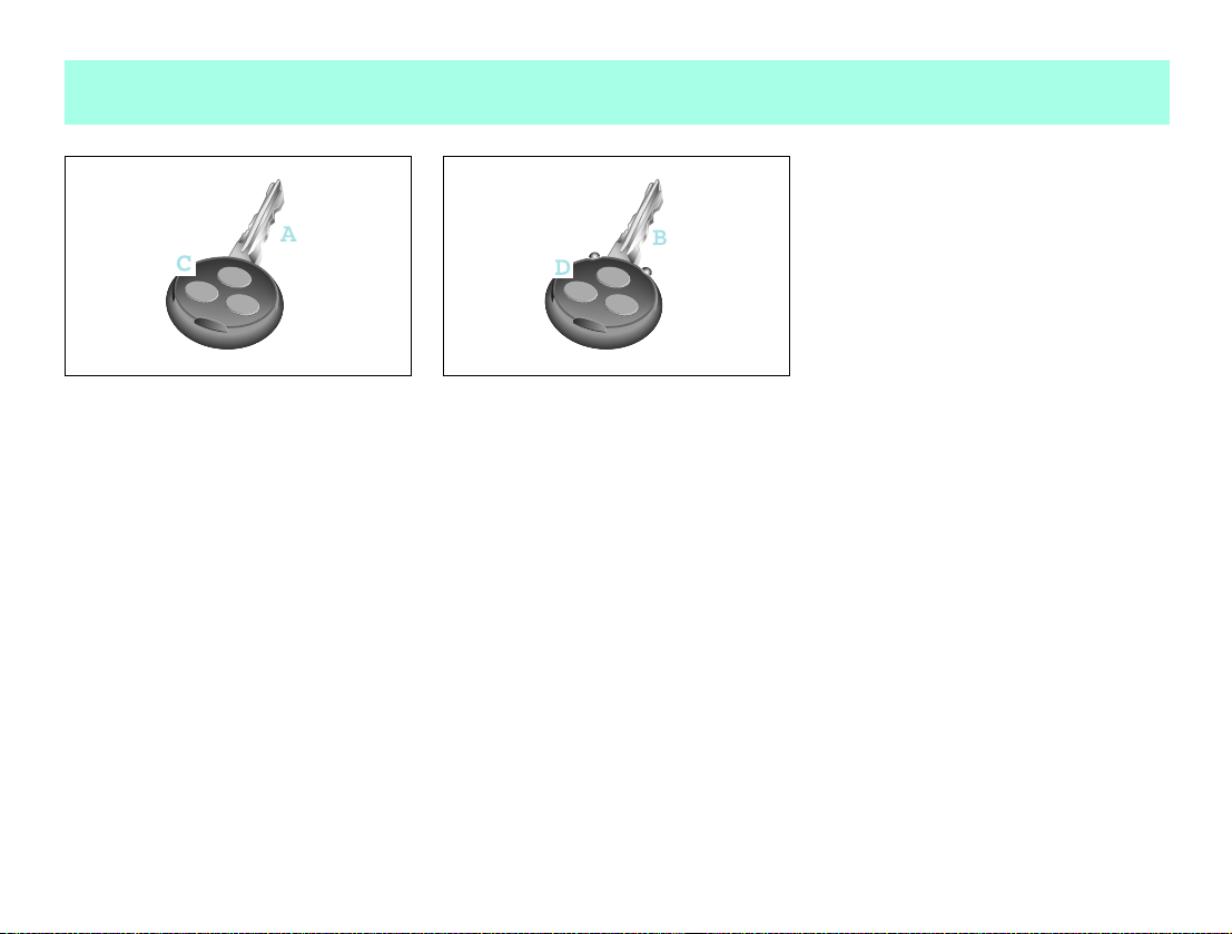
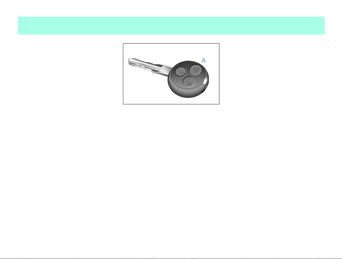
Your car's keys
Your vehicle can be ordered with keys op
erated by radio or infrared remote con
trol*.
쮿 Car key (A) with button for radio remote
control (C).
>Note!
Should you have problems with your radio
remote control in certain areas, please
get in touch with a qualified specialist
workshop such as a smart center.
10 Blind date
쮿 Car key (B) with button for infrared re
mote control* (D).
>Note!
Additionally, you receive a spare trans
mitter battery and a spare key.
>Note!
Unlocking and locking the driver and
passenger doors can only be done using
the radio remote control function on the
ignition key.
Page 13
Unlocking and locking
Unlocking and locking the car from
the outside
Accident risk!
When opening the doors, take care
not to endanger other road users or ne
cessitate other vehicles to swerve and
potentially cause an accident.
Make sure that nobody is endangered
when opening the doors.
Unlock and lock the car in the following
manner:
Unlocking the car with the remote
control
쮿 Press button (A) once.
> The turn signal lights flash once.
> The car's doors can be opened.
>Note!
The remote control has an operating
range of up to 15 metres. This can fluctu
ate greatly as a consequence of local con
ditions (reflective or absorbing objects)
and interference emitted by other radio
transmission systems. Similarly, the op
erating range fluctuates in line with the
direction from which the remote control
is activated.
Blind date 11
Page 14
Unlocking and locking
Locking the car with the remote control
Danger of injury!
Never leave children unsuper
vised in the vehicle. They could open a
locked door from the inside or start the
vehicle if the key is left in it and
thereby endanger themselves and oth
ers. You should therefore take the key
with you when leaving the vehicle, even
if you are only leaving it for a short
time.
Do not leave children unsupervised in
the car, even if they are secured by a
child restraint system. Children could
injure themselves on parts of the vehi
cle or be severely or even fatally
harmed by prolonged exposure to in
tense heat or cold.
쮿 Close the car's doors.
쮿 Press button (A) once.
> The turn signal lights flash three
times.
> The door lock display (B) flashes red.
The exterior and interior lighting comes
on and then goes off again after
12 seconds.
>Important!
Please make sure that you do not inad
vertently activate the remote control.
The automatic locking functions
Autorelock function
If you do not open either the driver or
passenger door after unlocking the car
with the remote control, the doors will be
locked again automatically after one
minute.
>Note!
Never leave your keys lying in the car.
You could lock yourself out!
12 Blind date
Page 15
Unlocking and locking
Drive lock function*
The vehicle doors are centrally locked
from a speed of approximately 14 km/h.
The drive lock function is switched off at
delivery.
Switching on the drive lock function
쮿 Switch off the ignition.
쮿 Press the central locking switch and
the locking button on the remote con
trol device at the same time.
> You will hear an acoustic signal. The
drive lock function is switched on.
Switching off the drive lock function
쮿 Switch off the ignition.
쮿 Press the central locking switch and
the unlocking button on the remote
control at the same time.
> You will hear an acoustic signal. The
drive lock function is switched off.
>Note!
For safety reasons, the sunroof top can
only be closed using the switch on the in
side of the vehicle.
>Important!
The remote control has an operating
range of up to 15 metres (approx. 50 ft).
Take care that you do not inadvertently
open your car's sunroof top.
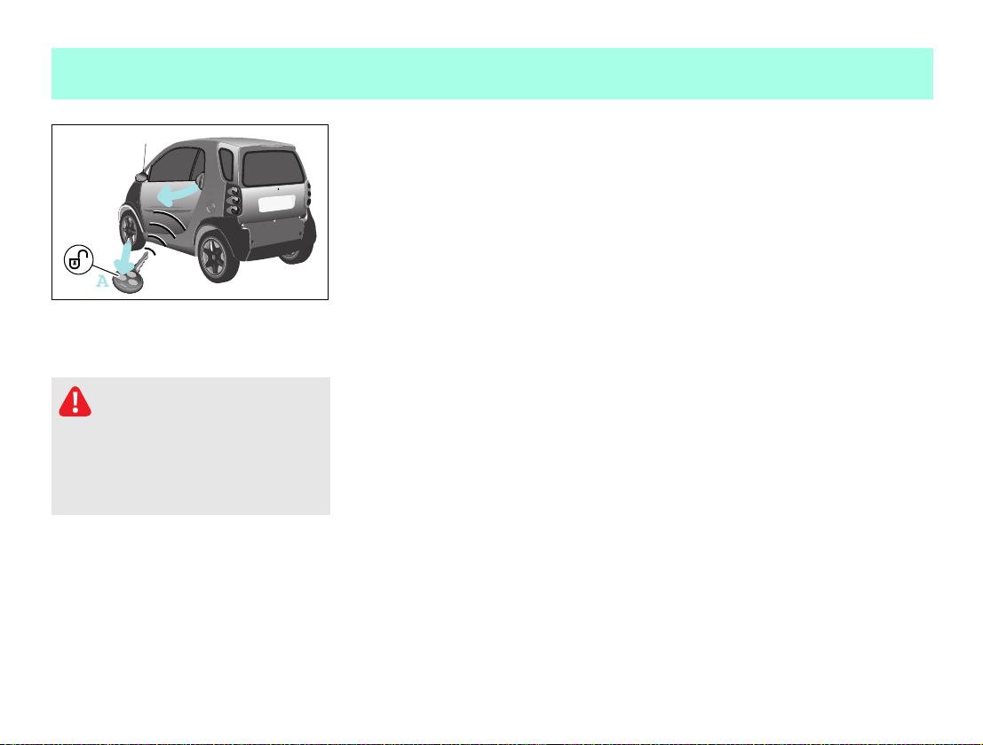
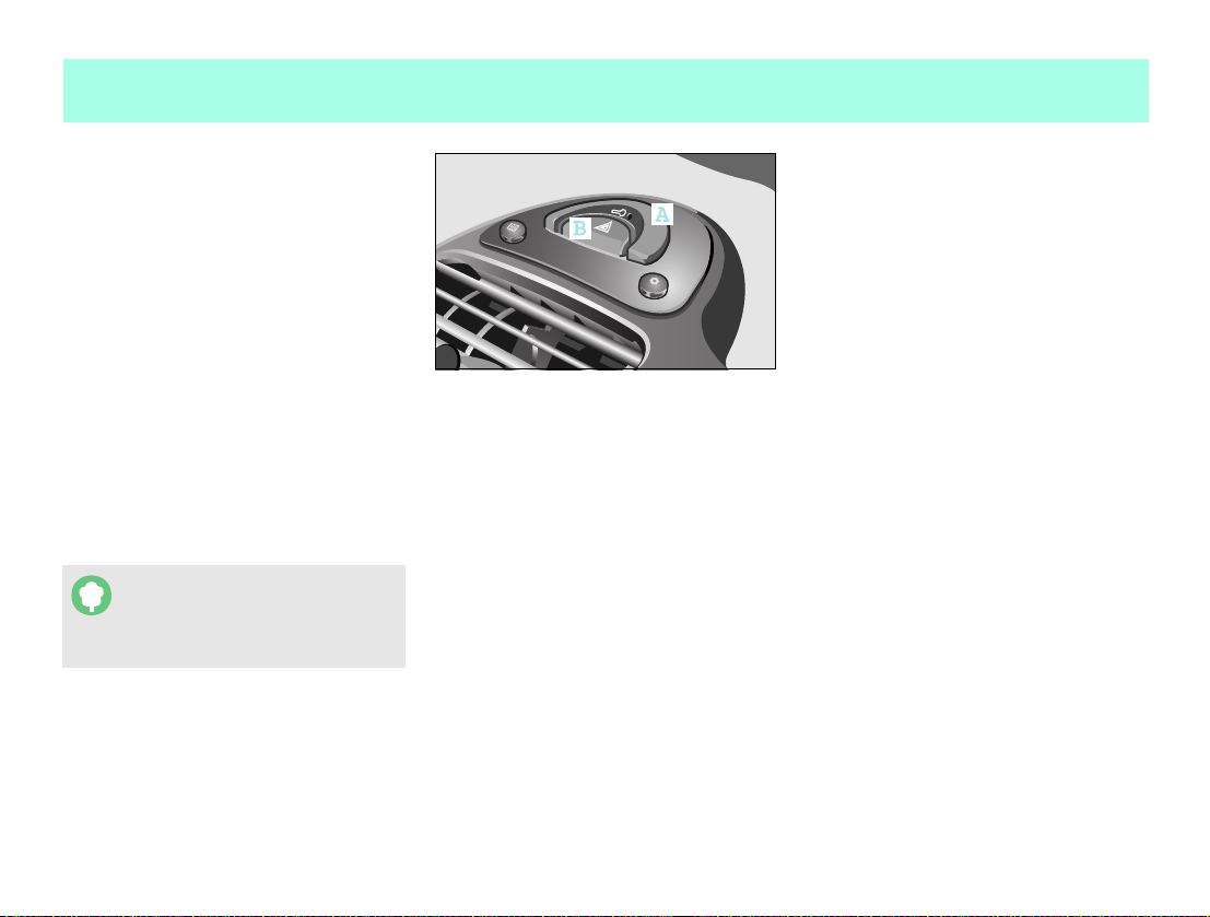
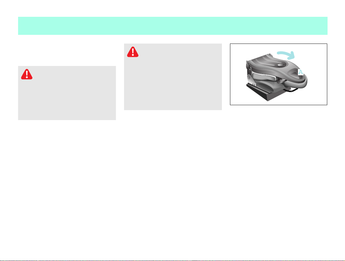
Opening and unlocking the sunroof top
(smart cabrio only)
You can open the sunroof top of your vehi
cle from the outside by pressing button
(A).
Convenience operation comprises the
following functions:
Complete opening of the sunroof top.
Unlocking of the rear soft top.
Unlocking of the rear soft top in its
folded and locked position.
Blind date 13
Page 16
Unlocking and locking
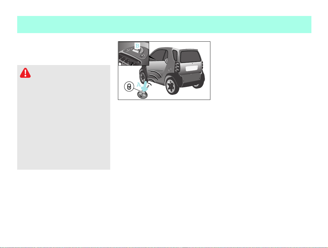
Locking and unlocking the car from
the inside
How to lock the car from the inside
쮿 Press the central locking switch (A) for
2seconds.
> The central locking mechanism is
distinctly heard.
> The car is locked and will protect
you against any unwanted persons
entering the car when waiting,
such as at traffic lights.
> The door lock display (B) will flash
red (if ignition is OFF).
If the vehicle will not lock using the
remote control although the battery of
the remote control has sufficient
voltage:
쮿 Open the driver door.
쮿 Switch on the ignition.
쮿 Press the central locking switch (A)
once.
> The door lock display (B) will flash
red for 5 seconds at double its nor
mal frequency.
> The car is locked if you switch the
ignition off within this period of 5
seconds.
쮿 Remove the key and exit the vehicle
with the key in your hand.
쮿 Close the driver door.
> The car is now locked.
How to unlock the car from the inside
쮿 You can unlock the doors by pulling the
door handle (C).
If the driver door is open a warning sig
nal will be sounded:
if a gear is engaged while the engine
is running and there is no pressure be
ing applied to either the footbrake or
the accelerator pedal.
if the lights are switched on and the
ignition is switched off.
Accident risk!
Do not leave children unsuper
vised in the vehicle. They could open a
door from the inside – even if it is
locked – and thereby endanger them
selves or others.
14 Blind date
Page 17
Unlocking and locking
How to recognise when the transmitter
battery in the key will soon be spent:
The turn signal lights flash 9 times in
quick succession when you lock the car.
Cause:
> The remote control transmitter bat
tery is almost spent.
> You will be able to use the remote
control approx. 100 more times.
Remedy:
> Replace the transmitter battery
> Have the transmitter battery re
placed by a qualified specialist
workshop, such as a smart center.
1
or
>Note!
If you fail to replace the transmitter
battery, after approximately 100 presses
of the remote control
you will not be able to lock or unlock
the car.
you will not be able to deactivate the
electronic immobiliser.
Environment!
Always dispose of discharged
transmitter batteries in an environ
mentallyfriendly manner.
1 A spare transmitter battery is included as part of the standard delivery scope.
you will not be able to start the car.
you will, however, be able to unlock the
central locking function by opening the
tailgate with the car key.
If the vehicle will not lock using the
remote control because the battery of the
remote control is spent:
If you can no longer lock the car using the
remote control an d you do not have a spare
transmitter battery on hand, please pro
ceed as follows:
쮿 Open the driver door.
쮿 Turn the key in the ignition switch to
position 0.
쮿 Press the central locking switch (A) un
til the door lock display (B) starts to
flash.
쮿 Turn the key in the ignition switch to
position 1 and then finally to position
0.
쮿 Take the keys out of the car with you and
close the doors.
쮿 The car is now locked.
Blind date 15
Page 18
Unlocking and locking
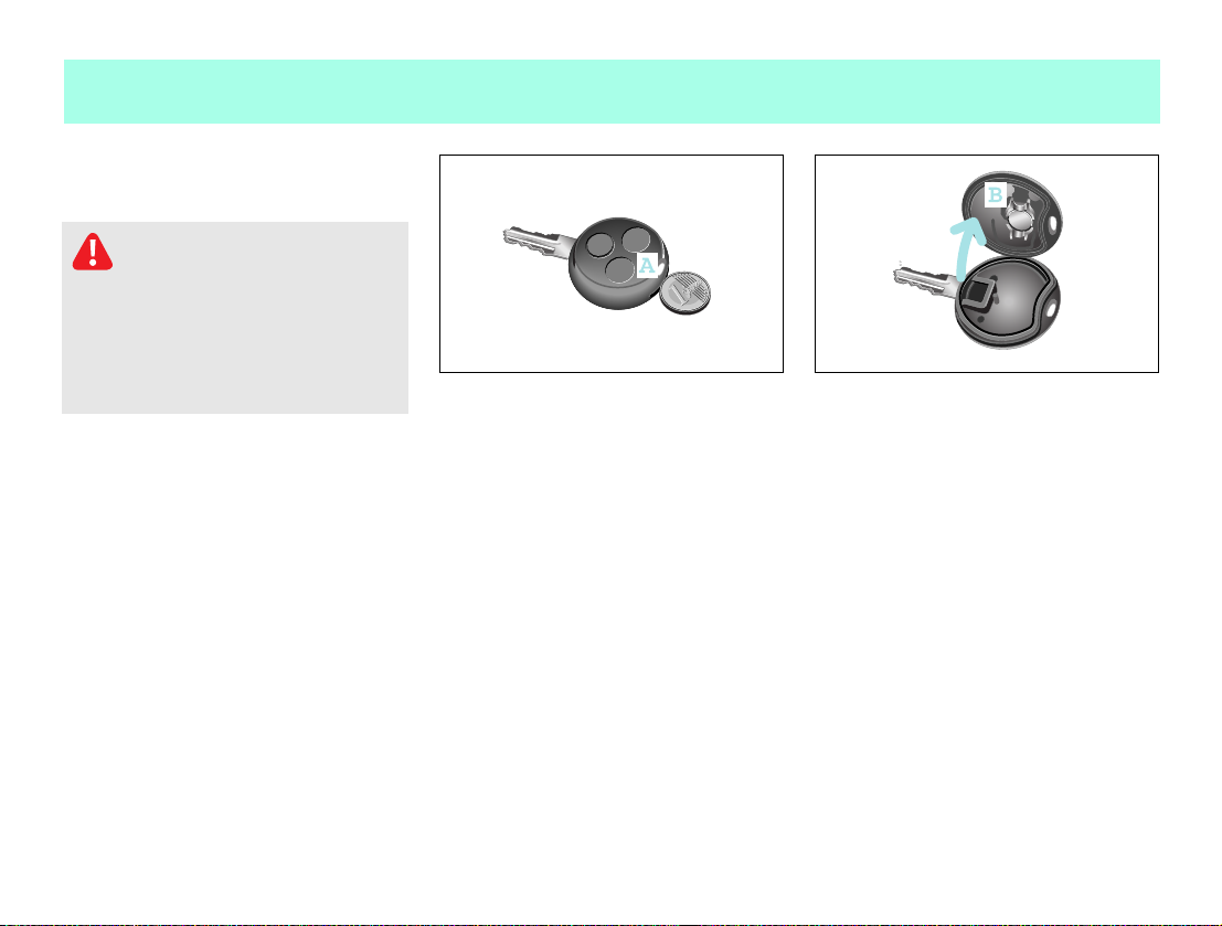
Replacing the transmitter battery
Danger of poisoning!
Batteries contain toxic and caus
tic substances. For this reason, keep
batteries away from children.
If a battery is swallowed, consult a doc
tor immediately.
Swallowing a transmitter battery can
cause serious health problems.
쮿 Use a coin to prise open the top half of
the key casing (A).
>Note!
Replace the remote control's transmitter
battery every 2 years at the latest.
Otherwise there is a danger of leakage!
The remote control could be destroyed.
쮿 Take the transmitter battery (B) out of
the board.
쮿 Insert the new transmitter battery,
checking that the polarity is correct.
> Type of battery: lithium cell CR 1225
>Note!
Check the polarity when inserting the
new transmitter battery.
Otherwise damage may occur to parts in
the electrical system.
쮿 Press both sides of the key casing back
together again.
16 Blind date
Page 19

Adjusting the seats
Adjusting the seats
Adjust the driver seat to the correct po
sition relative to the pedals and the
steering wheel before starting a journey.
Accident risk!
Only adjust the driver seat while
the vehicle is stationary. You will oth
erwise be distracted from the traffic
situation and the movement of the seat
could cause you to lose control of the
vehicle and result in an accident.
Danger of injury!
When adjusting the seat, make
sure that no one is trapped.
Observe the notes on the airbag system.
Danger of injury!
To reduce the risk of serious or
fatal injuries in an accident involving
rapid deceleration, e.g. with an air
bag inflating within a matter of milli
seconds, or if the brakes are applied
abruptly, please note the following:
All vehicle occupants must select a
seat position that allows the seat
belt to be worn correctly and that is
as far away from the airbag as possi
ble.
The driver seat position must allow
the driver to drive the vehicle safe
ly. The driver's arms must be slightly
bent when holding the steering
wheel. The driver must maintain a
distance from the pedals that allows
him to depress these fully.
Move the front passenger seat as far
back as possible, especially if a
child is secured in a restraint sys
tem* on this seat.
Vehicle occupants should always
wear their seat belt correctly and
position their backrest as close to
the vertical as possible. The head
restraint should support the back of
your head at about eye level.
Danger of injury!
Take the car to a qualified spe
cialist workshop, e.g. a smart center if
the seats have become damaged.
The seat is an integral part of the car's
safety system in the same way as
e.g. seat belts and airbags. Its safety
function can only be upheld if the seats
are free of damage.
Blind date 17
Page 20
Adjusting the seats
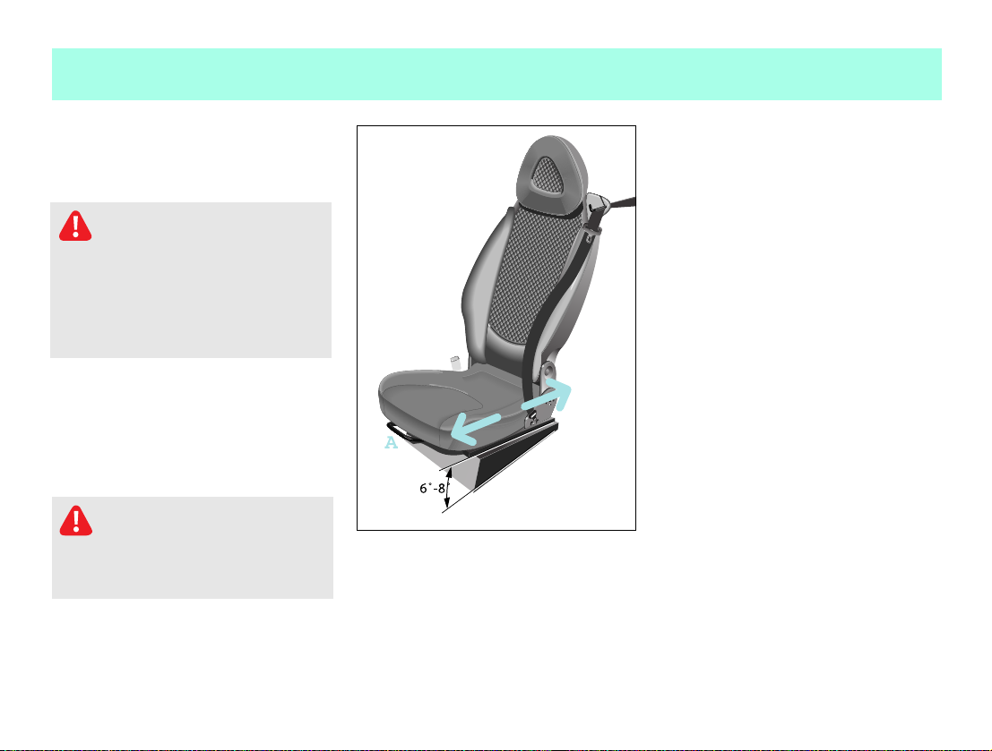
Longitudinal seat adjustment 쮿 Pull up the handle (A).
쮿 Move the seat to the desired position.
쮿 Release the handle.
> The locking mechanism must audibly
Accident risk!
Whenever the seat has been moved
forward or back, ensure that it engages
properly in position, as unexpected
movement or adjustment of the seat
while the car is being driven could
cause the driver to lose control and re
sult in an accident.
Danger of injury!
Do not insert your hands into the
seat rail when adjusting the seat's lon
gitudinal position. This represents a
considerable risk of injury.
engage on both sides.
Seat height adjustment
The seat guide is inclined in the hori
zontal plane. Longitudinal seat adjust
ment also alters the seat height.
18 Blind date
Page 21
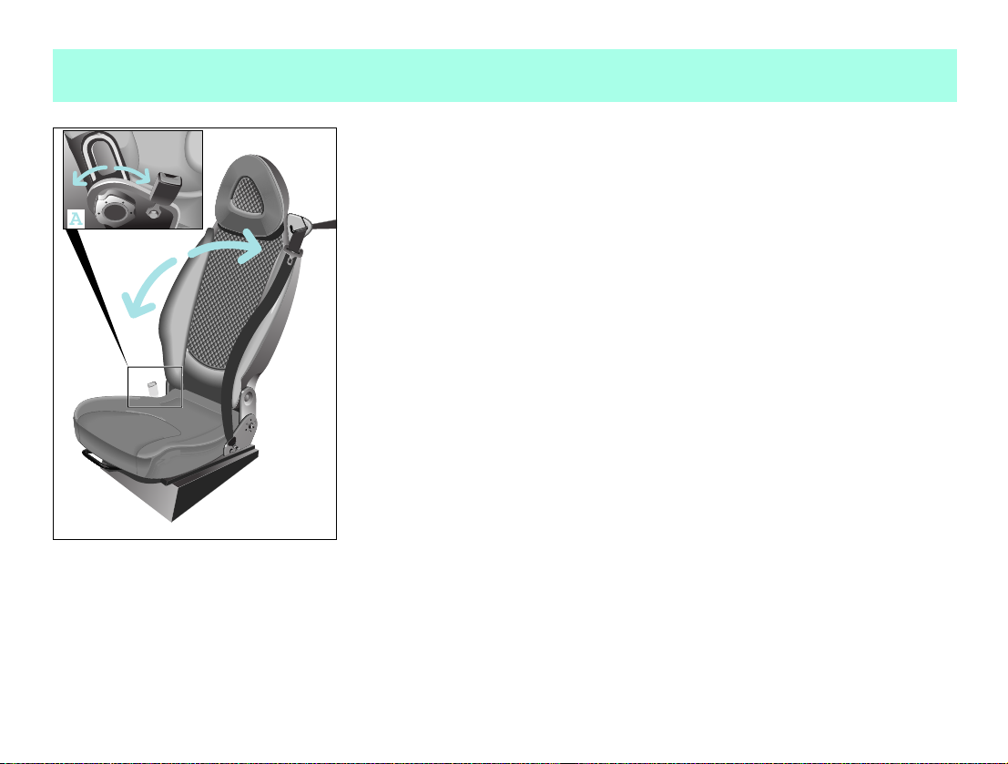
Adjusting the backrest inclination
쮿 Release the backrest.
쮿 Turn handwheel (A) forwards or back
wards.
>Note!
Only the driver seat can be adjusted.
Adjusting the seats
Blind date 19
Page 22
Adjusting the seats
Front passenger seat, folding down
Danger of injury!
Insert only suitable, sealed con
tainers in the stowage compartment.
Occupants otherwise could be injured
by the receptacles or their contents in
the event of an accident, a sudden brak
ing manoeuvre or a rapid change of di
rection.
Danger of injury!
Do not place any hot beverages or
glass bottles in the stowage compart
ment while driving. In the event of an
accident, a sudden braking manoeuvre
or a rapid change of direction,
the hot beverage can be spilt and
scald you and others,
glass bottles can be flung out and in
jure you and others.
Once folded down, you can use the passen
ger seat
as a storage space for small objects
(A).
as extra storage space.
>Note!
Please note the loading regulations (see
page 199) contained in these operating
instructions!
20 Blind date
Page 23
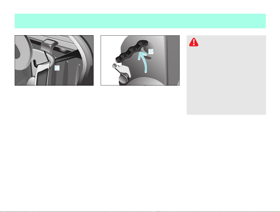
To fold the seat down:
쮿 Remove the seat belt from its belt
guide (C).
쮿 Slide the passenger seat into its cen
tre position.
쮿 Press both levers (D) backwards at the
same time.
> The backrest will move forward a few
millimetres out of its locked posi
tion.
쮿 Release both levers.
쮿 Fold the backrest forwards.
To fold back:
쮿 Pull backrest upwards and push it back
into position until both levers audibly
engage.
쮿 Place the seat belt back into the belt
guide (C).
Adjusting the seats
Danger of injury!
When returning the passenger
backrest to its upright position,
please ensure that
nobody becomes trapped,
no obstacles are jammed in the lock,
both levers audibly engage. Other
wise, in the event of an accident, a
sudden application of the brakes or a
rapid change of direction, the seat
backrest may fail to prevent any ob
jects stored in the luggage compart
ment from being propelled forwards,
exposing the occupants to the risk of
injury.
Blind date 21
Page 24
Mirrors, adjustment
Mirrors, adjustment
Accident risk!
The outside mirrors show objects
reduced in size. The objects are closer
than they appear. You could misinter
pret the distance to vehicles behind
you and cause an accident, e.g. when
changing lanes. Therefore, ensure that
you are aware of the actual distance to
vehicles behind you by also looking
over your shoulder.
Ensure that the outside and inside mir
rors are correctly set before starting a
journey. Only then can the driver be sure
that the view to the rear is unobstructed.
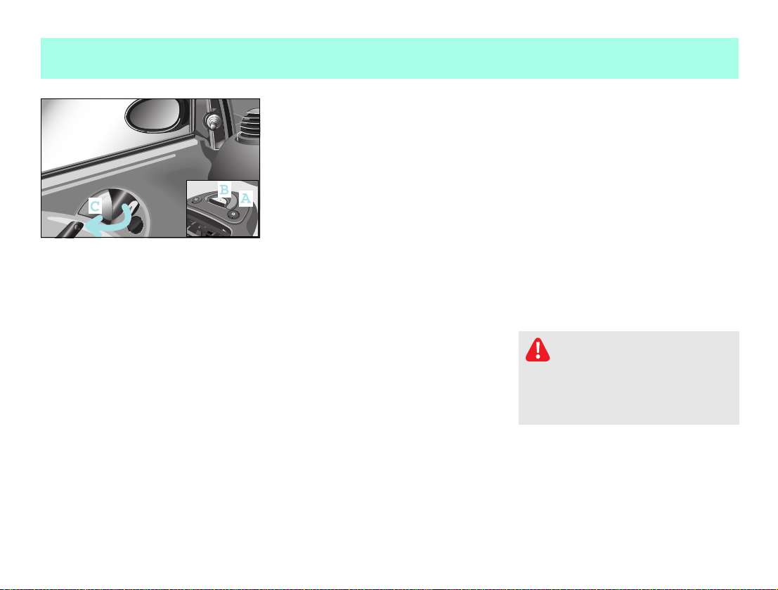
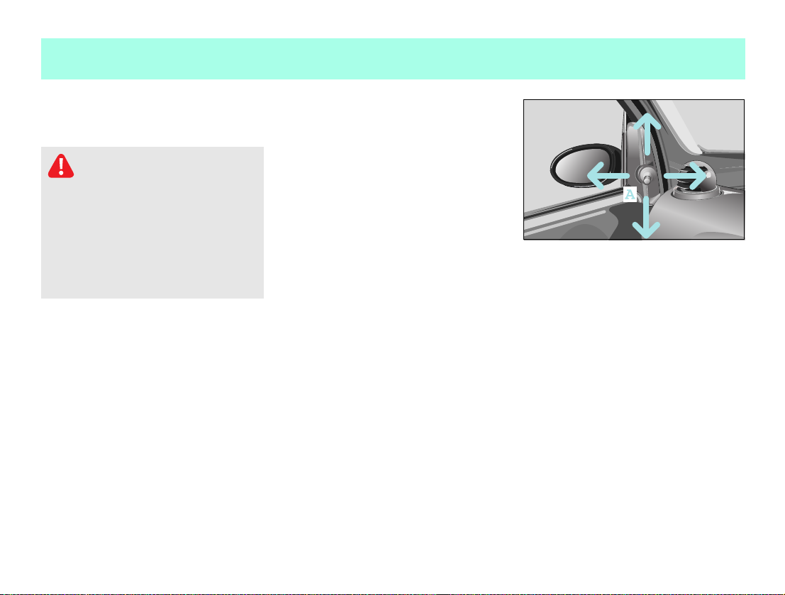
Manually adjustable outside mirror
쮿 Adjust the outside mirrors by turning
lever (A).
22 Blind date
Page 25
>Note!
The outside mirrors can only be adjusted
when the ignition is switched on.
Mirrors, adjustment
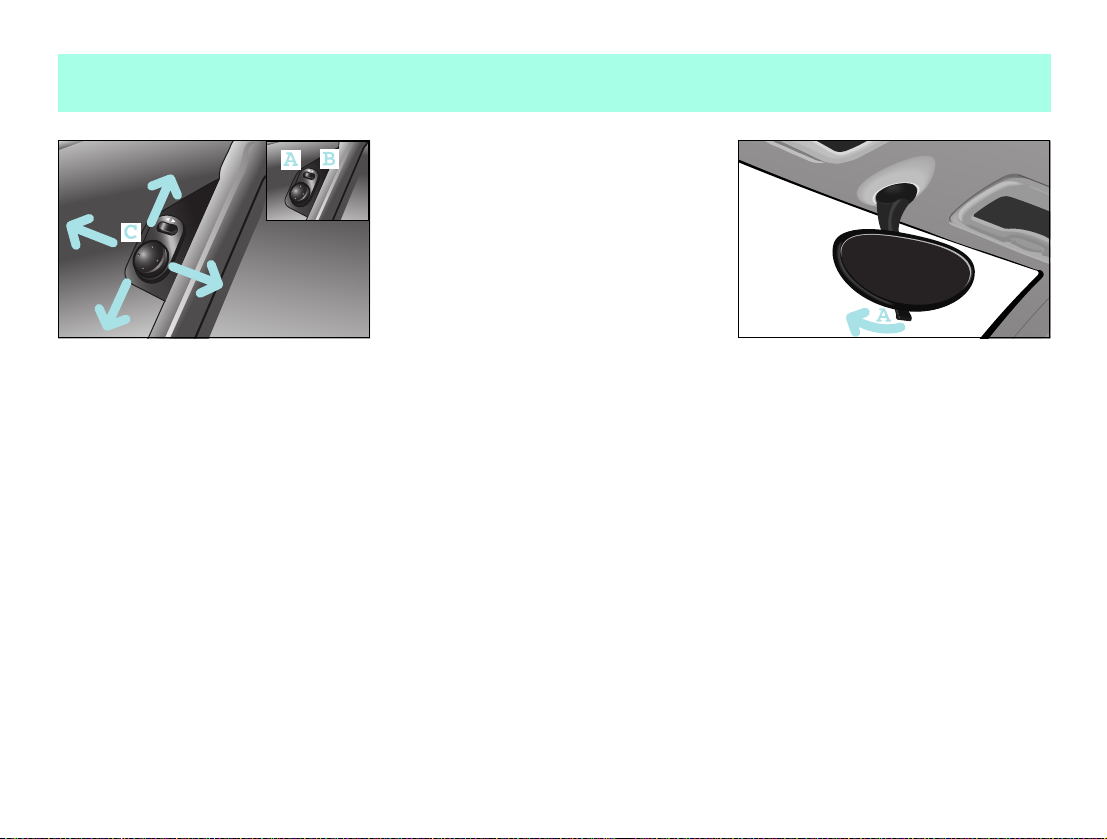
Electrically adjustable outside mirror*
The control knob is located on the driver
door.
쮿 The outside mirrors can be infinitely
adjusted by swivelling the control
knob (C).
Setting the adjustment side
쮿 Press the rocker switch.
Driver side (A)
Passenger side (B)
Adjusting the inside rearview mirror
쮿 Set the rearview mirror to the desired
position by hand.
To avoid being dazzled by oncoming traf
fic when driving at night:
쮿 Deflect the inside rearview mirror by
pulling lever (A).
> The view to the rear is retained.
Blind date 23
Page 26
Power windows
Power windows
Opening and closing the side windows
Danger of injury!
Make sure that nobody can become
trapped as you close a side window. If
there is a risk of trapping, press the
switch to open the windows.
Never leave children unsupervised in
the vehicle. They could e.g. injure
themselves by opening and closing the
windows!
The side windows can be opened and
closed by the electric power windows
when the ignition is on.
To open
쮿 Press the rocker switch (A) downwards.
To close
쮿 Press the rocker switch (A) upwards.
>Note!
The windows do not close automatically
when the car is locked.
24 Blind date
Page 27

Seat belts
Seat belts
The seat belts with integrated belt ten
sioners and belt force limiters combine
with the airbags to form a restraint sys
tem that offers maximum safety in the
event of an accident.
Danger of injury!
Airbags represent an additional
form of protection but are no substitute
for wearing a seat belt. To reduce the
risk of serious or fatal injuries, make
sure that all occupants – in particular,
pregnant women – wear their seat belt
correctly at all times, have adopted a
normal sitting position, and that the
seat is positioned as close to the ver
tical as possible.
Danger of injury!
A seat belt which is not worn,
which is worn incorrectly, or which has
not been engaged in the seat belt buck
le correctly, cannot perform its in
tended protective function. Under cer
tain circumstances this could even
cause severe or fatal injuries. You
should therefore make sure that all oc
cupants particularly pregnant
women – are always wearing their seat
belt correctly.
Make sure that the belt:
runs over the hip bone as low down as
possible, i.e. across the hip joint
and not across the stomach.
fits closely.
is not twisted.
runs across the middle of your shoul
der.
does not run across your neck or un
der your arm.
fits closely across your pelvic area,
by pulling upwards on the shoulder
section of the belt.
Do not secure any objects with a seat
belt if it is being used by one of the ve
hicle's occupants.
Avoid wearing bulky clothing, e.g. a
winter coat.
Do not position the belt strap across
sharpedged or fragile objects, espe
cially if these are located on or in your
clothing, e.g. spectacles, pencils or
keys. The seat belt strap could be dam
aged and you could be injured.
Only one person should use each seat
belt at any one time.
On no account should children travel
sitting on the lap of another occupant.
It would not be possible to restrain the
child, and the child or other vehicle
occupants could be injured seriously
in the event of abrupt braking or even
fatally in the event of an accident.
Blind date 25
Page 28

Seat belts
Danger of injury!
Persons under 1.50 m in height and
children under twelve years of age can
not fasten the seat belts properly. They
therefore require additional suitable
restraint systems on appropriate seats
for protection in an accident. Always
follow the manufacturer's installation
instructions when fitting a child re
straint system*.
Danger of injury!
A seat belt only offers its intend
ed degree of protection if the backrest
is positioned as close to the vertical as
possible and the occupant is sitting
upright. Avoid seat positions that pre
vent the seat belt from lying correctly
across the wearer's body. Position the
backrest as vertically as possible. Do
not drive with the backrest reclined
too far back. Otherwise, you could be
seriously or even fatally injured in the
event of an accident or sudden braking.
Danger of injury!
Modifications to or work not per
formed correctly on restraint systems
(seat belts, anchorages, belt tension
ers, belt force limiters or airbags) or
their wiring, as well as work on other
networked electronic systems, may pre
vent the restraint systems from working
correctly. Airbags or belt tensioners
could e.g. fail to operate in accidents
where the rate of deceleration exceeds
the tripping threshold, or be activated
unintentionally. Never carry out any
modifications on the restraint sys
tems. Never tamper with electronic
components and their software.
26 Blind date
Page 29

Danger of injury!
The seat belt cannot function cor
rectly if the belt or buckle is dirty or
damaged. Keep the belt and buckle
clean, otherwise the belt tongue cannot
engage correctly.
Check the seat belts regularly to ensure
that
they are not damaged,
they are not running across sharp
edges,
are not trapped.
Otherwise the belt could tear in the
event of an accident. You or others
could be seriously or fatally injured.
Have seat belts which have been dam
aged or subjected to heavy loads in an
accident replaced and have their an
chorages checked.
For safety reasons, smart gmbh recom
mends using only seat belts that smart
gmbh has specifically approved for
your vehicle.
Seat belts
Blind date 27
Page 30
Seat belts
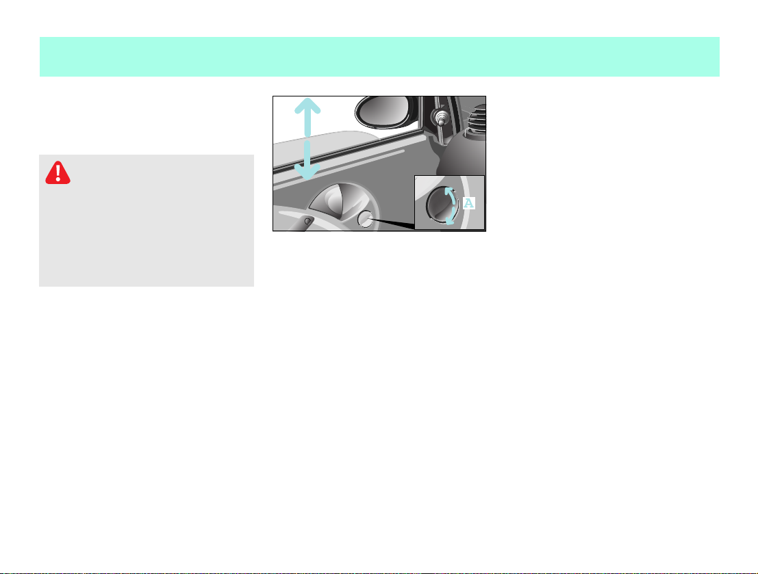
Seat belt height adjustment
The car has threestage seat belt height
adjustment capability integrated into
the seat.
The seat belt can run
through the belt guide (A),
above the belt guide,
below the belt guide.
>Note!
If the seat belt is to be run above or below
the seat belt guide, the belt must be taken
out of the guide.
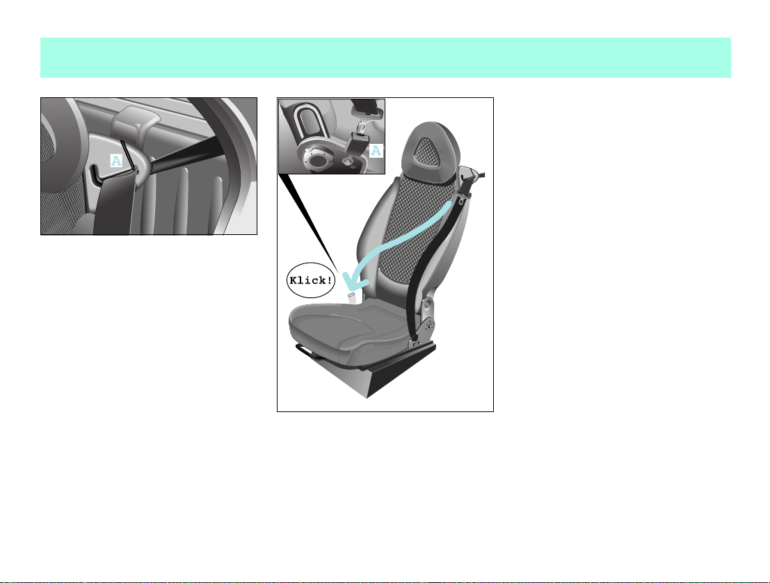
Putting on the seat belts
쮿 Take a seat.
쮿 Pull the seat belt without jerking it
from the roller.
쮿 Pull the belt across your shoulder.
> Your back must be leaning against
the backrest.
쮿 Click the seat belt into the buckle (A).
Taking off the seat belts
쮿 Press the red button on the belt buckle.
쮿 Let the belt run back into the belt
guide.
> The belt is automatically reeled
back into the roller.
28 Blind date
Page 31

Belt tensioners and belt force limiters
Belt tensioners and belt force
limiters
The seat belts are equipped with
belt tensioners,
a belt force limiter,
the functions of which are explained be
low.
Belt tensioners
tension the seat belts when activated,
so that they lie tightly across the body.
are only triggered in collisions with
high vehicle deceleration/accelera
tion in the longitudinal direction,
e.g. a headon collision.
> If the airbag indicator light comes
on, your belt tensioner has been ac
tivated.
>Note!
Do not fasten the seat belt on the front
passenger side if it is not occupied. In
the event of an accident, the belt ten
sioner would be triggered unnecessarily.
>Note!
Belt tensioners cannot compensate for:
incorrect seated positions,
seat belts worn incorrectly.
Belt tensioners do not actively pull the
occupants back against the seat back
rests.
Belt force limiters
reduce the force exerted by the belt on
the occupants when activated in the
event of an accident.
The belt force limiter is designed to
operate in unison with the front airbag,
which absorbs a portion of the seat belt's
decelerating forces, distributing the
load over a larger area.
If the ignition is switched on, the belt
tensioner is activated:
if the restraint systems are operation
al.
for each threepoint seat belt that is
fastened properly.
in the event of a headon or rearend
collision if the vehicle is decelerated
or accelerated sufficiently in the lon
gitudinal direction at the start of im
pact.
in certain rollover situations if the
need for additional protection is de
tected.
Blind date 29
Page 32

Belt tensioners and belt force limiters
If the belt tensioners are triggered, you
will hear a loud noise that fundamentally
represents no risk to your hearing. Some
dust may be generated.
Danger of injury!
Have belt tensioners which have
been triggered replaced at a qualified
specialist workshop which has the nec
essary specialist knowledge and tools
to carry out the work required. smart
gmbh recommends that you visit a smart
center for this. In particular, work rel
evant to safety or on safetyrelated
systems must be carried out at a quali
fied specialist workshop.
Comply with safety regulations when
disposing of belt tensioners. These
regulations can be viewed in every
qualified specialist workshop such as
a smart center.
30 Blind date
Page 33

Cockpit, lefthand drive model
a Gearshifts from the steering wheel*
b Control lever
c Instrument cluster
d Upper centre console
e Lower centre console
f Shift lever console
Cockpit, lefthand drive model
gAUX jack
Blind date 31
Page 34

Cockpit, righthand drive model
Cockpit, righthand drive model
a Gearshifts from the steering wheel*
b Control lever
c Instrument cluster
d Upper centre console
e Lower centre console
f Shift lever console
32 Blind date
Page 35

Control levers
Control levers
left
ALights
0 = off, 1 = parking lights, 2 = low beam
lights,
3 = rear fog lamp
B Turn signal lights
Indicating a right or left turn
C Mainbeam headlamps
1 = high beam lights, 0 = off, 1 =
headlight flashers
Control lever
right
A Wipe windscreen
2 = wiper speed stage 2, 1 = wiper speed
stage 1, 0 = off,
1 = interval wiping
B Wiping and washing windows
2 = rear window washing, 1 = rear
window interval wiping, 0 = off, 1 =
windscreen washing
C Switching the cruise control* and
limiter* on/off
D Cruise control* and limiter* func
tions
Blind date 33
Page 36

Instrument cluster, lefthand drive model
km/
!
Instrument cluster, lefthand drive model
AIndicator lights
B Display
C Speedometer
Indicator lights
abs (a)
Brake system (b)
High beams (c)
1 Only for vehicles with a diesel engine.
Rear fog lamp (d)
esp (e)
Airbag (f)
Turn signal lights (g)
Battery (h)
Oil pressure (i)
Engine check (j)
Diesel engine preheating
1
Heater booster
(l)
1
(k)
34 Blind date
Page 37

Instrument cluster, righthand drive model
AIndicator lights
B Display
C Speedometer
Indicator lights
abs (a)
Brake system (b)
High beams (c)
1 Only for vehicles with a diesel engine.
Instrument cluster, righthand drive model
Rear fog lamp (d)
esp (e)
Airbag (f)
Turn signal lights (g)
Battery (h)
Oil pressure (i)
Engine check (j)
Diesel engine preheating
1
Heater booster
(l)
1
(k)
Blind date 35
Page 38

Instrument cluster
Instrument cluster
abs indicator light
It lights up:
when the ignition is switched on (self
diagnosis).
> The light goes out after engine is
started or
> goes out after no more than
10 seconds.
36 Blind date
abs indicator light abs indicator light
in abs limp home mode (fault in the abs
system).
Accident risk!
If the abs system is faulty, the
wheels could lock when the brakes are
applied. This limits the steerability
of the vehicle when braking and the
braking distance may increase. If abs
is deactivated due to a fault, then esp
is also deactivated.
The risk of your vehicle skidding is
then increased in certain situations.
You should therefore always adapt your
driving style to suit the prevailing
road and weather conditions.
쮿 Take the car to a qualified
specialist workshop, e.g. a smart
center, without delay.
when the abs system fails, together
with the brake system indicator light.
쮿 Immediately park your car away from
moving traffic.
쮿 When you exit the vehicle, secure it
against rolling away with the
handbrake.
쮿 Do not drive any further.
쮿 Call a breakdown recovery service
such as smartmove Assistance or a
qualified specialist workshop
such as a smart center.
Page 39

Instrument cluster
Brake system indicator light
It lights up:
when the ignition is switched on.
> The light goes out after the engine
starts or
> goes out after no more than 10 sec
onds.
with handbrake applied.
Brake system indicator light
It lights up:
when brake circuit fails or brake fluid
level is too low.
쮿 Immediately park your car away from
moving traffic.
쮿 When you exit the vehicle, secure it
against rolling away with the
handbrake.
쮿 Do not drive any further.
쮿 Call a breakdown recovery service
such as smartmove Assistance or a
qualified specialist workshop
such as a smart center.
when the abs system malfunctions, to
gether with abs indicator light.
쮿 Take the car to a qualified
specialist workshop, e.g. a smart
center, without delay.
High beam indicator light
It lights up:
when high beam headlights are on.
when the headlight flashers are used.
Blind date 37
Page 40

Instrument cluster
Rear fog lamp indicator light
It lights up:
when the rear fog lamp is switched on.
38 Blind date
esp indicator light
It flashes:
> when esp actively intervenes.
Light stays on permanently:
> for system failure,
> when esp is not responding.
It may be possible to clear a system mal
function by restarting the car.
쮿 If the indicator light still does not go
out, take the car to a qualified spe
cialist workshop, e.g. a smart center,
without delay.
>Note!
The operating principle of esp and addi
tional information to this regard can be
found on page 165.
esp indicator light
Accident risk!
If esp is no longer functioning,
there is a greater risk that your car
could skid in certain driving situa
tions. You should therefore always
adapt your driving style to suit the
prevailing road and weather condi
tions.
Page 41

Instrument cluster
Airbag indicator light
The airbag indicator light signals to you
that there is a fault in the safety systems
of the:
Airbags
Belt tensioners
Child seat recognition system
>Note!
The operating principle of the airbags
and additional information to this re
gard can be found starting on page 166.
Airbag indicator light Airbag indicator light
It lights up:
Danger of injury!
If the indicator light does not
come on when you switch on the ignition
or does not go out again after a few sec
onds once the engine is running or
comes on again, there is a fault.
Some systems could be triggered unin
tentionally or not be triggered at all in
the event of an accident with high de
celeration. In such cases, immediately
have the safety system of your vehicle
checked and repaired at a qualified
specialist workshop which has the nec
essary specialist knowledge and tools
to carry out the work required. smart
gmbh recommends that you visit a smart
center for this. It is particularly im
portant to have safetyrelevant work
and work on safetyrelevant systems
performed by a qualified specialist
workshop.
with the ignition switched on.
The subsequent selfdiagnosis of the
safety systems yields the following re
sults:
1. Airbag indicator light goes out after a
maximum of 4 seconds:
> No fault detected.
> The airbag system is OK.
2. The airbag indicator light goes out af
ter a maximum of 4 seconds for approx
imately 1 second, then it comes on
again and stays on:
> A fault has been detected.
> Do not sit on the passenger seat; this
applies in particular to children
secured by a rearwardfacing child
restraint system.
쮿 Take the car to a qualified
specialist workshop, e.g. a smart
center, without delay.
Blind date 39
Page 42

Instrument cluster
Airbag indicator light
3. The airbag indicator light flashes for
15 seconds, then illuminates perma
nently:
> smart baby carrier (original smart
accessory) identified on the passen
ger seat.
> Passenger airbag and the side air
bags* (if available) are deactivated.
4. Airbag indicator light flashes perma
nently:
> Fault with child seat recognition
system.
> Do not sit on the passenger seat; this
applies in particular to children
secured by a rearwardfacing child
restraint system.
> Take the car to a qualified special
ist workshop, e.g. a smart center,
without delay.
Airbag indicator light
Danger of injury!
If the airbag indicator light
does not come on when a smart baby car
rier is fitted to the passenger seat, the
passenger airbag has not been deacti
vated. This can result in the child be
coming seriously to fatally injured in
the event of an accident when the pas
senger airbag is triggered, especially
if the child is in the direct vicinity of
the passenger airbag at the time the
airbag is triggered.
The passenger airbag is only deacti
vated when you fit an original smart
baby carrier to the passenger's seat.
Danger of injury!
If the passenger airbag is acti
vated, e.g. the airbag indicator light
does not illuminate, you must never se
cure a child on the passenger seat in a
rearwardfacing child restraint sys
tem.
Also observe the corresponding warn
ing sticker on the instrument panel.
If you have installed a special smart
baby carrier on the passenger seat and
the airbag indicator light does not il
luminate (restraint system not detect
ed), have the automatic restraint
system detection checked by a quali
fied specialist workshop which has the
necessary specialist knowledge and
tools to carry out the required work.
smart gmbh recommends that you visit a
smart center for this.
Until this problem has been rectified,
do not carry children in the car, as they
could sustain serious or even fatal in
juries in the event of an accident.
40 Blind date
Page 43

Turn signal indicator light
It flashes:
when ignition is switched on, if:
> the indicator lever is activated.
> the hazard warning lights are
switched on.
>Note!
If a turn signal light malfunctions, the
flashing frequency is doubled.
쮿 Replace the bulb (see page 232) or
쮿 Take the car to a qualified specialist
workshop, e.g. a smart center.
Battery indicator light
It lights up:
when the ignition is switched on.
> The indicator light goes out if the
engine is running.
If it comes on during a journey or fails to
go out after the engine has been started,
the battery is not being charged.
쮿 Immediately park your car away from
moving traffic.
쮿 When you exit the vehicle, secure it
against rolling away with the
handbrake.
쮿 Do not drive any further.
쮿 Call a breakdown recovery service
such as smartmove Assistance or a
qualified specialist workshop
such as a smart center.
>Important!
The drive belt may have broken.
If this occurs, the engine may suffer dam
age if driven any further.
Instrument cluster
Oil pressure indicator light
It lights up:
when the ignition is switched on.
> Indicator light goes out if the en
gine is started and oil pressure is
sufficient.
Beware of the following!
If the indicator light goes out before
the engine is started, it is not func
tioning.
쮿 Check the oil level.
쮿 Take the car to a qualified
specialist workshop, e.g. a smart
center.
Blind date 41
Page 44

Instrument cluster
Oil pressure indicator light
If it comes on during a journey:
쮿 Immediately park your car away from
moving traffic.
쮿 Secure your car against rolling away
if you have to leave it.
쮿 Do not drive any further.
쮿 Call a breakdown recovery service
such as smartmove Assistance or a
qualified specialist workshop
such as a smart center.
>Important!
Continue to drive the car or keeping the
engine running may lead to the engine
being destroyed.
>Note!
The oil pressure indicator light is a
warning light that displays low oil pres
sure. Check your engine's oil level at
regular intervals (see page 206).
1 Only for vehicles with a diesel engine.
42 Blind date
1
Preglow indicator light
It lights up:
when the ignition is switched on.
> When the indicator light extin
guishes, the engine is ready to be
started.
>Note!
If the engine is already at operating
temperature you can start it without the
preheater.
1
Heater booster indicator light
>Note!
The heater booster can only be switched
on if the engine is running.
It lights up:
when the heater booster is switched on.
> In order to switch on the heater
booster you must move the air tem
perature slider as far to the right as
it will go.
It goes out:
when the heater booster is switched
off.
> In order to switch off the heater
booster you must move the air tem
perature slider to the left.
Page 45

Engine check indicator light
It lights up:
when the ignition is switched on.
> Indicator light goes out after the
engine is started or after 10 seconds
if the engine electronics are func
tioning properly.
If it comes on during a journey:
쮿 Take the car to a qualified specialist
workshop, e.g. a smart center, without
delay.
Instrument cluster
Blind date 43
Page 46

Instrument cluster
Display
You can see the following in the display:
(a) Fuel tank gauge
(b) Gearshift indicator or automatic dis
play/electronic immobiliser
(c) Coolant temperature display
(d) Multiple display with tank capacity
residual litre indicator
(e) Frost warning*
(f) Service interval display
Display illumination
The display illumination lights up:
when the lights are switched on.
when the ignition is switched on.
Display illumination goes out when the
ignition and the lights are switched off.
>Note!
Display illumination is dimmed if the
lights are switched on along with the ig
nition.
44 Blind date
Page 47

Instrument cluster
Fuel tank gauge
The tank's fuel level is displayed with
the aid of five ovalshaped segments.
The number of shaded segments indicates
the level of fuel in the tank.
If all five segments are dark, the tank is
full.
Reserve range
You are in the reserve range if there are
no more than 5 litres of fuel in the tank.
If this occurs,
the fuel pump symbol and the residual
litres arrow start to flash,
the multifunction display shows the
fuel tank capacity with an accuracy of
0.5 litres (residual litres display),
you should call at the next nearest fill
ing station.
>Notes on the residual litres display!
The residual litres display is only active
in the reserve range.
The switchover function of the multi
function display (see page 48) remains
active.
If all 5 segments are flashing, there is a
problem in transferring the fill level
information.
쮿 Find a filling station, completely re
fuel the vehicle and drive according to
the odometer.
쮿 Take the car to a qualified specialist
workshop, e.g. a smart center.
Blind date 45
Page 48

Instrument cluster
Neutral, no gear engaged
Reverse gear is engaged
No gear engaged
Shifting system fault
Automatic mode
Digital gear indicator
The gear indicator displays information
on the sequential transmission:
Gear engaged
Activated electronic immobiliser (see
page 140 ff)
Upshift
Downshift
1 Only for the smart fortwo cabrio.
46 Blind date
CAN (data bus) malfunction (icon flash
es)
1
Rear soft top
place
not correctly locked in
Page 49

Instrument cluster
Coolant temperature gauge
The coolant temperature is displayed by
5 ovalshaped elements.
The number of shaded elements indicate
the coolant temperature.
At normal operating temperature,
three segments are shaded.
> The coolant temperature is at least
80 °C.
If 5 segments are dark, then the °C sym
bol starts to flash.
쮿 Immediately park your car away from
moving traffic.
쮿 Secure your car against rolling away
if you have to leave it.
쮿 Do not drive any further.
쮿 Call a breakdown recovery service
such as smartmove Assistance or a
qualified specialist workshop
such as a smart center.
If the temperature continues to in
crease, the 5 segments will also start to
flash after 15 seconds.
쮿 Avoid driving at high engine speeds
and do not drive fast.
쮿 Immediately park your car away from
moving traffic.
쮿 Secure your car against rolling away
if you have to leave it.
쮿 Do not drive any further.
쮿 Call a breakdown recovery service
such as smartmove Assistance or a
qualified specialist workshop
such as a smart center.
>Important!
Continue to drive the car or keeping the
engine running may lead to the engine
being destroyed.
Blind date 47
Page 50

Instrument cluster
Multifunction display
쮿 In each case press button (A) once to
switch between the following func
tions:
Trip odometer
Daily trip odometer (when held down
for a few seconds it returns to zero)
Outside temperature*
Residual litres display (when there
are fewer than 5 litres of fuel in the
fuel tank)
>Note on outside temperature display*
The temperature display will respond
sluggishly when temperatures rapidly
rise or fall.
This ensures that the temperature read
ing is not falsified by the heat of the en
gine e.g. when the car is at a standstill
or travelling relatively slowly.
48 Blind date
Page 51

Frost warning*
Accident risk!
Even if the temperature is
slightly above freezing, there could
still be ice on the road, particularly in
wooded areas and on bridges. The vehi
cle could skid if you fail to adapt your
driving style. You should therefore al
ways adapt your driving style and speed
to suit the weather conditions.
Instrument cluster
If the outside temperature falls below 3
°C, the display alerts you to the fact that
there could be ice on the road.
> The outside temperature appears in the
display.
> A snowflake symbol flashes for 60
seconds in the display.
Blind date 49
Page 52

Instrument cluster
Service interval display
The service interval display informs you
of the point in time and scope of the next
service visit.
An upcoming service visit is shown in the
display approximately one month in ad
vance. After the engine is started, this
information is shown in kilometres (km)
or in days for approximately 10 seconds,
depending on the kilometre reading.
One spanner or two spanners is/are
shown in the display, depending on if
service A or B is due.
50 Blind date
Activate service interval display
쮿 Briefly press button (A) on the multi
function display twice.
Page 53

Upper centre console
aTachometer*
b Cockpit clock*
c Central locking switch
d Hazard warning lamps
1 Only for the smart fortwo coupé.
e Rear window heater
f Driver’s heated seat*
g Passenger’s heated seat*
h Air conditioning plus*
1
Upper centre console
Blind date 51
Page 54

Upper centre console
Cockpit clock*
Setting the time
The buttons for setting the time are
located on the rear of the cockpit clock.
Advancing the time
쮿 Press button (A) once.
> The time displayed changes by one
minute.
쮿 Press button (A) for more than
2seconds.
> The speed at which the time changes
accelerates.
52 Blind date
Reversing the time
쮿 Press button (B) once.
> The time displayed changes by one
minute.
쮿 Press button (B) for more than
2seconds.
> The speed at which the time changes
accelerates.
The cockpit clock can be adapted to suit
your needs
Your cockpit clock
can be turned through approx. 90°.
> This ensures that you or the person
sitting next to you has an ideal view
of the clock.
is backlit the moment you switch your
car's lights on.
> This enables you to see the display at
all times, even when it is dark out
side.
>Note!
Do not hang any objects on the cockpit
clock.
This could cause the clock to tear out of
its mounting and badly damage it.
Page 55

Upper centre console
Tachometer*
Driving in the optimum engine speed
range helps you to
save fuel.
take good care of the engine.
>Important!
Always pay attention to the gear shift
recommendations indicated in your car's
gear indicator.
>Important!
For safety reasons, no conversions may be
made to the tachometer.
>Note!
Do not hang any objects on the tachome
ter.
This could cause the tachometer to be
torn from its mountings and badly damage
it.
The tachometer can be adapted to suit
your needs
Your tachometer
can be turned through approx. 90°.
> This gives you an ideal view of the
instrument, no matter how your seat
is positioned.
is backlit the moment you switch your
car's lights on.
> This enables you to see the display at
all times, even when it is dark out
side.
Blind date 53
Page 56

Upper centre console
Function
The tachometer displays the engine
speed in units of 1,000 rpm.
The optimum engine speed ranges (rpm) are: Petrol engines Diesel engines
Driving off 1,000 2,000 1,000 2,000
Normal operation at constant speed 2,000 3,000 1,800 3,000
Brief periods of acceleration, e.g. when passing 3,000 6,300 3,000 4,400
54 Blind date
Page 57

Lower centre console
AHeater/ventilation
B Audio/telematics devices
CStorage compartment
a Fresh air/recirculated air selector
b Air temperature/heater/heater
cAir distribution
dBlower
1 Only for vehicles with a diesel engine.
booster
1
Lower centre console
eFront fog lamps*
fInterior light
g 12volt power socket
Blind date 55
Page 58

Shift lever console
3
6
2
1
9
5
4
8
7
0
Shift lever console
a Telephone console*
b Gearshift lever
c Power glass sliding roof switch*
rear soft top switch2
d Ignition switch
1 With the fortwo coupé
2 With the fortwo cabrio
1
or
56 Blind date
Page 59

Contents
>Lights . . . . . . . . . . . . . . . . . . . . . . .58
>Headlight range control. . . . . . . . .61
>Interior lights . . . . . . . . . . . . . . . .62
>Fog lamps . . . . . . . . . . . . . . . . . . .63
>Turn signal lights. . . . . . . . . . . . . .65
>Warning sounds and
indicator lights . . . . . . . . . . . . . . .66
>>Light conditions.
As your vehicle is easy to operate because all control elements are located where you would expect them to be, even navigating in the
dark is a cinch. But go ahead and try it out in daylight first.
Page 60

Lights
Lights
Accident risk!
Switch your lights on in good
time
when it is raining heavily,
when it starts to get dark.
Vehicles are detected easier in traffic
if they have their lights on.
Switching on the lights
The control lever for the lights is located
to the left of the steering wheel.
By turning the rotary control from its de
fault position of 0, the following occurs:
Stage 1 the parking lights are switched
on.
Stage 2 low beam lights are switched on.
Stage 3 the rear fog lamp and the low
beam lights are switched on.
>Note!
When you switch the ignition off, the low
beam lights are also switched off. They
come on again automatically when the en
gine is restarted.
>Note!
If you drive in countries in which the
side of the road driven on is opposite
that of the country in which the vehicle is
approved, oncoming traffic may be
blinded by the asymmetric low beam
lights. In this case, have the headlights
converted to the symmetric low beam
lights for these countries. This conver
sion can be carried out in a qualified
specialist workshop such as a smart cen
ter.
58 Light conditions
Page 61

Lights
High beam lights
The high beam lights can only be
switched on if
the ignition is turned over.
the rotary control is turned to at least
stage 2 (low beam lights).
Switching on the high beam lights
쮿 Press the lever away from the steering
wheel (1).
> The lever engages.
Switching off the high beam lights
쮿 Pull the lever towards the steering
wheel (2).
> The lever is back in its default posi
tion.
Coming home function*
The coming home function allows you to
switch on your car's lights and the inte
rior lighting if the vehicle is parked in
a dark area or you are approaching it.
12 seconds is the time the lights on your
vehicle will stay on to help you find your
way.
When leaving the car
쮿 Remove the ignition key.
쮿 Briefly press the locking button on the
remote control twice in succession.
> The car is locked.
> The driving lights are switched on
automatically and go out again after
12 seconds.
Upon returning to the car
쮿 Briefly press the unlocking button on
the remote control twice in succession.
> The car is unlocked.
> The car's exterior and interior
lights comes on and then go off again
after 12 seconds.
Light conditions 59
Page 62

Lights
Daytime driving lights*
If your car is equipped with daytime
driving lights
lights come on automatically when you
drive off.
>Note!
When the daytime driving lights are ac
1
, the low beam and parking
Switching on daytime driving lights
쮿 Switch off the ignition.
쮿 Operate the headlight flashers.
쮿 At the same time, press the button for
locking the car on the car key.
> A signal sounds by way of confirma
tion that the daytime driving lights
are switched on.
tivated, the high beam lights can only be
turned on when the light control lever is
in stage 2 (low beam lights).
Switching off daytime driving lights
쮿 Switch off the ignition.
쮿 Operate the headlight flashers.
쮿 At the same time press the button for
unlocking the car on the car key.
> A signal sounds by way of confirma
tion that the daytime driving lights
are switched off.
1 Standard specification in countries where daytime driving lights are required by law.
60 Light conditions
Page 63

Headlight range control
>Note!
Note that the headlight range adjustment
must be reset to position 0 after you have
unloaded the vehicle.
Headlight range control
The headlight range adjustment enables
you to adapt the headlights to suit the
load status of your car.
Adjusting the headlight range
The basic setting, this means:
no payload,
driver seat occupied,
headlight range adjustment position
0
ensures that you
obtain the best possible visibility
conditions for the driver (A),
do not dazzle drivers of oncoming
vehicles.
If the light cone changes due to the vehi
cle load (B):
쮿 Turn the headlight range adjuster
wheel (C) to the corresponding posi
tion until the basic light position set
ting is reestablished.
Switch
position
0 Driver seat occupied.
1 Driver seat occupied and
2 Driver seat, passenger seat
Load
Driver and passenger seats
occupied.
maximum load in the
luggage compartment (50
kg).
occupied and maximum
payload in the luggage
compartment (50 kg).
Light conditions 61
Page 64

Interior lights
Interior lights
The interior lights are located on the
centre console (A).
at the rear of the car (B).
The interior lights both illuminate
briefly when you open the doors.
The lights go off
immediately after the ignition is
switched off if all doors are closed.
after 15 seconds, if all doors are
closed.
after 10 minutes if at least one door is
open.
The lights also illuminate when you lock
or unlock the car with the remote control.
The lights go off
immediately after the ignition is
switched on.
after 30 seconds.
Both lights continuously illuminate when
you press the toggle switchtype interior
light (A) on the lower edge.
The lights go off when you press the tog
gle switch on the upper edge.
>Important!
When leaving the car, make sure that
the interior lights are not set to per
manent operation.
one of the doors is not left open for
longer.
This could cause car's battery to run flat.
62 Light conditions
Page 65

Fog lamps
Switching off the fog lamps
쮿 Press switch (A) again.
>Note!
If you switch the lights off, the fog lamps
are also switched off. Switching the
lights back on again does not automati
cally switch the fog lamps on.
Fog lamps
Front fog lamps*
The front fog lamps (A) should only be
switched on
in fog
where visibility is poor because of
rain, or
where vision is impaired because of
snow.
Accident risk!
Adapt your speed and driving
style according to the visibility con
ditions. Other vehicles could be driv
ing only a short distance in front of you
without you being able to spot them in
good time and brake.
Switching on the fog lamps
The front fog lamps can only be switched
on if the parking lights are already on.
쮿 Press switch (A) once.
> The following lights are switched
on:
the fog lamps
the integrated indicator light
>Note!
Please observe the national statutory
regulations regarding the use of front
fog lamps.
Light conditions 63
Page 66

Fog lamps
Switching off the rear fog lamp
쮿 Turn the rotary control to stage 0.
>Important!
Turn it back by one stage only if you wish
to continue driving with low beam lights
on.
Rear fog lamp
The control lever for the rear fog lamp (A)
is located to the left of the steering
wheel.
Accident risk!
The rear fog lamp should only be
switched on when visibility is down to
less than 50 metres. Vehicles following
behind may otherwise be dazzled.
64 Light conditions
Switching on the rear fog lamp
쮿 Turn the rotary control to the rear fog
lamp icon (stage 3).
> When the ignition is switched on, the
following lights also come on:
The rear fog lamp
The indicator light in the display
Page 67

Turn signal lights
Turn signal lights
The turn signal light control lever is lo
cated to the left of the steering wheel.
To signal turning right
쮿 Push it further upwards until you feel
it lock into place.
To signal turning left
쮿 Push it further downwards and allow it
to lock into place.
>Note!
The lever which is locked in place is then
returned to the neutral position
after turning.
via the automatic turn signal reset
function.
The control lever can also be returned to
its neutral position manually.
Turn signal lights with convenience
touchshifting
If you briefly press the control lever up
or down, the turn signal lights flash
three times on the corresponding side of
the car.
Light conditions 65
Page 68

Warning sounds and indicator lights
Warning sounds and indicator lights
Horn
쮿 Press anywhere on the steering wheel's
highlighted area.
> The horn sounds.
66 Light conditions
Headlight flashers
The control lever for the headlight flash
ers is located to the left of the steering
wheel.
> The headlight flashers remain active
for as long as the lever is pulled in
towards the steering wheel.
Hazard warning lights
쮿 To switch the hazard warning lights on,
press the red switch (A).
>This causes
all six turn signal lights to flash,
the turn signal indicator light to
start flashing when the ignition is
switched on, and
the hazard warning light switch
also to flash.
쮿 To switch the hazard warning lights
off, press the red switch again.
Page 69

Contents
>Audio/telematics devices*. . . . . . .68
>smart radio one* . . . . . . . . . . . . . .69
>smart radio three*. . . . . . . . . . . . .70
>smart radio five* . . . . . . . . . . . . . .71
>smart radio navigator* . . . . . . . . .72
>smart CD changer*. . . . . . . . . . . . .76
>CD box* . . . . . . . . . . . . . . . . . . . . .77
>Cassette box*. . . . . . . . . . . . . . . . .80
>Telephone console* . . . . . . . . . . . .83
>Universal handsfree system*. . . .86
>ipod*. . . . . . . . . . . . . . . . . . . . . . . .87
>smart sound package* . . . . . . . . . .88
>>Communication.
Your car is quite an entertaining vehicle in and of itself. However, should you prefer a little more variety while on the move, you can
listen to the radio, a cassette or CD.
These systems transform your car into an allround entertainer.
Page 70

Audio/telematics devices*
Audio/telematics devices*
Accident risk!
Acquaint yourself with the vari
ous functions of your audio, navigation
and telecommunications systems prior
to starting out on your journey to en
sure that you are not distracted in any
way from events on the road if you oper
ate them while driving.
For safety reasons, only operate the
system when the vehicle is stopped and
if traffic conditions permit.
Accident risk!
Always select a volume that al
lows you to still hear ambient sound in
your immediate vicinity (e.g. horns,
emergency rescue vehicles, police ve
hicles, etc.). You could otherwise cause
an accident.
Accident risk!
If you wish to have a radio other
than an original smart radio fitted in
your car, please always have the neces
sary work performed by a qualified
specialist workshop, such as a smart
center.
This is particularly important if there
had already been fitted a smart radio
five or if your car has a radio prein
stallation.
If a radio is connected up inexpertly,
important vehicle functions could fail.
On the following pages you will find a
brief description of the audio, naviga
tion and telecommunications systems
that are available for your smart fortwo
coupé and smart fortwo cabrio.
The devices are described with their full
complement of equipment, including ra
dio, cassette, and CD changer* modes. The
description for your individual equip
ment specification applies.
Please see the individual operating in
structions for detailed functions.
68 Communication
Page 71

smart radio one*
Basic settings Radio mode CD mode
Switch on/off, change volume (a)
TP on/off (b)
Clock (e)
Tone settings (f) changeable with but
ton (h)
EXPERT settings (g)
1 only in conjunction with the smart CD changer*
Select transmitter, store station (i)
Station search (c)
Station storing levels (FM1/FM2) (c)
with six memory slots per level (call
able by button (i))
Selector button, CD mode (d)
Scan tracks (h)
Select CD (i)
Select track (h)
Play tracks in random order (h)
smart radio one*
1
Communication 69
Page 72

smart radio three*
smart radio three*
Basic settings Radio mode Cassette mode CD mode
Switch on/off, change vol
ume (a)
TP on/off (b)
Clock (f)
Tone settings (g) changeable
with button (i)
EXPERT settings (h)
1 only in conjunction with the smart CD changer*
Select transmitter, store
station (j)
Station search (c)
Station storing levels (FM1/
FM2) (c) with six memory
slots per level (callable by
button (i))
Selector button for cassette,
CD mode/eject cassette (d)
Cassette compartment (e)
Scan tracks (i)
Briefly turn (i) to switch to
other side of cassette
Turn (i) for forward and re
verse
Selector button for cassette,
CD mode/eject cassette (d)
Scan tracks (i)
Select CD (j)
Select track (i)
Play tracks in random
order (i)
1
70 Communication
Page 73

smart radio five*
Basic settings Radio mode CD mode
Switch on/off, change volume (a)
TP on/off (b)
EXPERT settings (by pressing and hold
ing) (j)
Tone settings (k) changeable with but
ton (g)
1 only in conjunction with the smart CD changer*
Select station button, store station (d,
e, h, i)
Station search (g)
Station storing levels
(AM/FM1/FM2/FM3) (c)
with four memory slots per level (call
able by buttons (d, e, h, i)
Scan tracks (d)
Select CD1 (e, h)
Eject CD (f)
Select track (g)
Play tracks in random order (i)
smart radio five*
Communication 71
Page 74

smart radio navigator*
smart radio navigator*
Accident risk!
Acquaint yourself with the vari
ous functions of your smart navigation
system prior to starting out on your
journey to ensure that you are not dis
tracted in any way from events on the
road if you operate it while driving.
For safety reasons, only operate the
system when the vehicle is stopped and
if traffic conditions permit.
Accident risk!
Always select a volume that al
lows you to still hear ambient sound in
your immediate vicinity (e.g. horns,
emergency rescue vehicles, police ve
hicles, etc.). You could otherwise cause
an accident.
The smart navigation system offers
radio functions (VHF, short wave, me
dium wave and long wave reception),
a CD player which plays audio CDs, and
an
integrated navigation system with si
multaneous use of audio and navigation
functions.
CD drive
Audio CDs and the data media for the nav
igation system are played on the inte
grated CD drive.
Multifunction display
The multifunction display serves to vi
sualise the main functions with direc
tional arrows, letters, distance data and
schematic intersection displays. Voice
information supports the visual displays
and also helps you to arrive at your des
tination quickly and without any prob
lems.
>Note!
More detailed information on the navi
gation system functions can be found in
the operating instructions for your smart
navigation system.
72 Communication
Page 75

Radio control elements
a Switching device on or off
b Automatic forward search function
cMute switch
d Radio or CD player select
e Manual station setting and setting of
bass, treble, fader and balance
fMenu change
g Station memory and autostore function
h Station memory
i Station memory, PTY+ search and man
ual search run
j Station memory and PTY search
k Station memory and regional mode
l Station memory and switchover to RDS/
frequency mode
smart radio navigator*
m Automatic reverse search run
n Scan search function
Briefly plays receivable radio stations
o Selection: Bass, treble, fader, balance
p Volume control
Communication 73
Page 76

smart radio navigator*
CD control elements
a Switching device on or off
b Skip track, forward
cMute switch
dCD tray
e CD eject button
f Selection: Radio or CD mode
gSettings
Bass, treble, fader, balance
h Contrast setting
i Display of elapsed CD time, elapsed
track time and total playing time
j Music search forwards
k Music search backwards
l Repeat of current track on CD in tray
mRandom play
n Skip track, reverse
o Scan search function:
Briefly plays tracks
p Selection:
Bass, treble, fader, balance
q Volume control
74 Communication
Page 77

Navigation control elements
a Switching device on or off
b Interrupt navigation information or
switch off
cCD tray
d CD eject button
e Information button
f Menu select and confirmation of selec
tion
gBack to previous menu
h Selecting navigation mode
i Delete an entry or a stored destination
smart radio navigator*
jVIA function
kTMC function
l Traffic congestion
mIntermediate stop
n Selection: Bass, treble, fader, balance
o Volume control and playback of current
navigation information
Communication 75
Page 78

smart CD changer*
smart CD changer*
The smart CD changer is located under
neath the passenger seat.
>Note!
More detailed information on the CD
changer functions can be found in the op
erating instructions for the smart CD
changer.
76 Communication
Page 79

CD box*
CD box*
The CD box is located between the driver
and passenger footwells in the vertical
console.
>Note!
Removal is done in the reverse order.
Installing and removing
In lefthand drive model
쮿 Push the CD box on the cone on the ver
tical console until the back of the CD
box comes to rest against the vertical
console.
쮿 Screw the housing of the CD box hand
tight with the aid of a coin.
쮿 Check that the housing is located se
curely and fit the cover cap.
Communication 77
Page 80

CD box*
In righthand drive model
쮿 Guide the CD box up against the fixing
holes on the vertical console.
쮿 The housing of the CD box must rest
against the vertical console.
쮿 Screw the housing to the lefthand fix
ing hole with the aid of a coin.
쮿 Fold the CD trays open and secure the
CD box through the hole in the rear wall
with the second screw.
쮿 Check that the housing is located se
curely and fit the cover cap over the
lefthand screw.
>Note!
Removal is done in the reverse order.
Installation in conjunction with the
ashtray, the drinks holder* or the
cassette box*
If so, note that the ashtray always must
remain installed in the uppermost posi
tion and the drinks holder always in
stalled in the lowest position. Always
install the items in the vertical console
from top to bottom.
The individual elements are linked to
gether by guides.
쮿 Push the top side of the element to be
installed as far as it will go along the
guide on the underside of the element
already installed above it.
쮿 Before screwing the individual ele
ments tight, check that they are prop
erly interconnected and are located
flush one above the other.
78 Communication
Page 81

CD box*
Changing the pullout points of the CD
trays
In order to find the desired CD tray more
easily, you can place the pullout points
of the four CD trays at different posi
tions.
쮿 Swivel the frame with the CD tray out of
the housing past the snapin position
until it stops.
쮿 Press the CD tray (A) upwards out of the
frame.
쮿 Move the position arrow (B) of the CD
tray to one of the recesses (C) of the
frame.
> There are four possibilities (1 4)
for fitting the CD tray and position
ing the pullout points.
쮿 Press the CD tray and the frame
together so that the four clips (D)
interlock.
> The frame with the CD tray can be
swivelled back.
쮿 Repeat this process to position the
pullout points of the other CD trays to
the desired positions.
Communication 79
Page 82

Cassette box*
Cassette box*
The cassette box is located between the
driver and passenger footwells in the
vertical console.
>Note!
Removal is done in the reverse order.
Installing and removing
In lefthand drive model
쮿 Push the cassette box on the cone on the
vertical console until the back of the
cassette box comes to rest against the
vertical console.
쮿 Screw the housing of the cassette box
handtight with the aid of a coin.
쮿 Check that the housing is located se
curely and fit the cover cap.
80 Communication
Page 83

Cassette box*
In righthand drive model
쮿 Guide the cassette box up against the
fixing holes on the vertical console.
쮿 The housing of the cassette box must
rest against the vertical console.
쮿 Screw the housing to the lefthand
fixing hole with the aid of a coin.
쮿 Fold the cassette trays open and secure
the cassette box through the hole in the
rear wall with the second screw.
쮿 Check that the housing is located se
curely and fit the cover cap over the
lefthand screw.
>Note!
Removal is done in the reverse order.
Installation in conjunction with the
drinks holder or the CD box
If so, note that the ashtray always must
remain installed in the uppermost posi
tion and the drinks holder always in
stalled in the lowest position.
Always install the items in the vertical
console from top to bottom.
The individual elements are linked to
gether by guides.
쮿 Push the top side of the element to be
installed as far as it will go along the
guide on the underside of the element
already installed above it.
쮿 Before screwing the individual ele
ments tight, check that they are prop
erly interconnected and are located
flush one above the other.
Communication 81
Page 84

Cassette box*
Changing the pullout points of the
cassette trays
In order to find the desired cassette tray
more easily, you can place the pullout
points of the four cassette trays at differ
ent positions.
쮿 Swivel the frame with the cassette tray
out of the housing past the snapin po
sition until it stops.
쮿 Press the cassette tray (A) upwards out
of the frame.
82 Communication
쮿 Move the position arrow (B) of the
cassette tray to one of the recesses (C)
of the frame.
> There are four possibilities (1 – 4)
for fitting the cassette tray and posi
tioning the pullout points.
쮿 Press the cassette tray and the frame
together such that the four clips (D)
interlock.
> The frame with the cassette tray can
be swivelled back.
쮿 Repeat this process to position the
pullout points of the other cassette
trays to the desired positions.
Page 85

Telephone console*
3
6
2
1
9
5
4
8
7
0
Telephone console*
Accident risk!
Mobile phones and twoway radio
equipment that do not have a low re
flection outside aerial may interfere
with the vehicle electronics and there
by jeopardise the operational safety of
the vehicle and your safety as well.
Therefore, use this equipment only if it
has been properly connected to a sepa
rate low reflection outside aerial.
Accident risk!
When operating mobile communi
cations equipment in the vehicle,
please observe the statutory require
ments of the respective country.
If operating communications equip
ment is legally approved while en
route, be sure that you do so only when
traffic allows. Otherwise you may fail
to recognise hazards and could conse
quently cause an accident and injure
yourself and others.
The telephone console provides for se
cure and convenient installation of your
mobile phone. There are suitable cradles
available for the various different makes
of mobile phone. In order to use a differ
ent mobile phone in the universal hands
free system*, all you need to do is
exchange the cradle.
The telephone console (A) is located in
front of the gearshift lever.
Installing and removing
If you have a drinks holder in the car, re
move this first (see operating instructions
for drinks holder).
Communication 83
Page 86

Telephone console*
쮿 Remove the cover cap on the centre tun
nel console.
쮿 Release the Torx screw beneath it us
ing a suitable screwdriver.
쮿 Pull up and remove the gearshift lever
knob (on vehicles with softouch*, take
care not to press the automatic button
when pulling it off!).
> The centre tunnel console can be
dismantled.
The centre tunnel console is fastened to
the vehicle by means of two detent hooks
at the front.
쮿 Bend open the console at the round in
serts.
쮿 Lift the centre tunnel console and re
move it.
쮿 Place the centre tunnel console on a
flat working surface.
쮿 Push the telephone console beneath the
centre tunnel console until the under
sides are parallel and the rounded sec
tion at the rear edge of the telephone
console is parallel with the insert in
the centre tunnel console.
쮿 Insert the enclosed screws through the
designated holes, and screw them di
rectly into the plastic of the centre
tunnel console.
84 Communication
Page 87

Telephone console*
쮿 Twist the screw back in.
쮿 Refit the cover cap.
쮿 Reattach the gearshift lever knob.
쮿 Mount the mobile phone cradle on the
3
2
6
1
5
9
4
8
7
0
upper side of the telephone console.
>Note!
More information on operating and in
stalling the cradles can be found in the
respective operating instructions.
If you lay the leads to your cradle beneath
the carpet for a neater appearance, you
can run the leads between the telephone
console and the centre tunnel console.
You can use the recess on the telephone
console for this.
As long as the centre tunnel console is not
fitted, you can lift up the carpet in this
area to run the cable for the universal
handsfree system beneath it. The loca
tion of the leads depends on the installa
tion location of the universal handsfree
system, and may vary.
Once the leads have been laid:
쮿 Bend the console open again at the
front and push it down.
쮿 Fit the assembled consoles back over
the gearshift bracket.
쮿 Ensure that the clips engage again.
Communication 85
Page 88

Universal handsfree system*
Universal handsfree system*
The universal handsfree system is con
nected up to the radio and loudspeaker
system. The audio signals are thus repro
duced via the car's loudspeakers, allow
ing the volume to be adjusted via the
radio.
While you are using the phone
the system is automatically activated,
the word
display,
audio programs are automatically mut
ed.
>Note!
More detailed information on the univer
sal handsfree system is available in its
operating instructions.
Phone appears in the radio
86 Communication
Page 89

ipod*
ipod*
Accident risk!
Keep focused on the events on the
road. Do not use the Apple iPod en
route. Doing so could distract you from
traffic and cause an accident.
For safety reasons, only operate the
system when the vehicle is stopped and
if traffic conditions permit.
As a driver, you assume full responsi
bility for road safety.
Please note that when driving at only 50
km/h, your car will cover 14 metres ev
ery second!
Controls
A Connection socket for the remote
control
B Connection socket for headphones
C Hold switch
D Display
EReverse button
F Menu button
G Playback/pause button
H Forward button
I Selection button
J Scroll pad
KHeadphones
L Dock connector connection
Communication 87
Page 90

smart sound package*
smart sound package*
In order to get the most out of your audio/
telematics equipment, the smart sound
package includes additional speakers
for power sound at hifi level.
You can connect mobile audio devices
such as an MP3 player via the AUX jack
(A) using a commercially available
3.5 mm jack plug.
The AUX jack is found in the stowage com
partment between the steering column
and the upper centre console
2
.
1
1 Does not apply to CD changer*
2 For lefthand drive models only
88 Communication
Page 91

Contents
>Sun visors . . . . . . . . . . . . . . . . . . . 90
>Sunroof visor* . . . . . . . . . . . . . . . . 92
>Power glass sliding roof* . . . . . . . 93
>Coat hooks . . . . . . . . . . . . . . . . . . . 95
>Heater/ventilation. . . . . . . . . . . . . 96
>Air conditioning plus*. . . . . . . . . 102
>Wipers . . . . . . . . . . . . . . . . . . . . . 105
>Rear window heater. . . . . . . . . . . 107
>Outside mirror heaters* . . . . . . . 108
>Seat heater* . . . . . . . . . . . . . . . . 109
>Car cover* . . . . . . . . . . . . . . . . . . 110
>>Weather outlook.
You can adjust to the weather by changing your clothes to suit. Similarly, your car offers a range of luxurious solutions such as, for
example CFCfree air conditioning plus or an electric heater booster for diesels.
Page 92

Sun visors
Sun visors
Protection against light from the front
쮿 Swivel the sun visor downwards.
쮿 Swivel the sun visor back up when the
sun is no longer blinding you and you
don't need it any more.
>Note!
The sun visors cannot be swivelled to
wards the side windows.
90 Weather outlook
Page 93

Sun visors
Mirror for the driver sun visor*
Accident risk!
Keep the mirrors in the sun vi
sors covered while driving. Dazzling
light could otherwise endanger your
self and others.
Fitting the mirror
The mirror for the driver sun visor is
glued into place.
쮿 Clean the area of the driver sun visor
to which it is to be affixed (A) with or
dinary washingup liquid or glass
cleaner.
>Note!
Do not use alcohol or acetone. This could
cause damage to the surface of the driver
sun visor.
Do not touch the mounting area with the
fingers, as this could impair the adhe
sive bond.
쮿 Dry the prepared area with a clean
paper towel.
쮿 Remove the protective film from the
two adhesive sections on the back of
the mirror.
쮿 Insert the mirror for the driver sun vi
sor into the fitting aperture (B) on the
sun visor and secure with the locating
pin.
쮿 Open the mirror cover.
쮿 Press both adhesive sections (A) on the
back of the mirror firmly against the
sun visor for about 20 seconds.
>Note!
The adhesive will take approx. 3 hours to
harden completely.
Weather outlook 91
Page 94

Sunroof visor*
Sunroof visor*
The sunroof visor serves to protect
against solar radiation and the buildup
of heat through the glass roof.
Its easytouse operation allows you to
slide the sunroof back and forth using
one hand only.
92 Weather outlook
Wind and sunroof visor* for power glass
sliding roof
This is only available together with the
power glass sliding roof.
Page 95

Power glass sliding roof*
Danger of injury!
The glass sliding roof has an ob
struction sensor feature. When closing
it, nevertheless make sure that no one
is trapped.
Power glass sliding roof*
Switch for the power glass sliding roof
Opening and closing of the glass sliding
roof is controlled via a rocker switch. It
is located on the right, next to the gear
shift lever. This enables the glass slid
ing roof to be opened to any desired
position.
Raising the glass sliding roof
쮿 Press the rocker switch (when glass
sliding roof closed) briefly to posi
tion A.
Weather outlook 93
Page 96

Power glass sliding roof*
Opening the glass sliding roof
쮿 Press the rocker switch to position A
and hold it there.
Closing the glass sliding roof
쮿 Press the rocker switch to position B
and hold it there until the roof is com
pletely closed.
94 Weather outlook
Page 97

Coat hooks
Hang your jacket up on one of the coat
hooks provided
at the rear roof rail (A) or
on the back of the seats (B).
Coat hooks
Weather outlook 95
Page 98

Heater/ventilation
Heater/ventilation
Your heater and ventilation controls
Fresh air/recirculated air selector (A)
Blower (B)
Air distribution (C)
Ai r temperature/heater/heater booster
(D)
96 Weather outlook
Switching the blower on
You can set the blower to four different
levels:
Blower on max./defrost (A) (for effi
cient defrosting and fast drying of the
fogged windows)
Blower middle setting (B)
Blower slow setting (C)
Blower off (D)
Adjusting the air nozzles
Rotary air nozzles
쮿 You can adjust the rotary air nozzle (A)
by hand to suit.
Centre air nozzle
쮿 You can adjust the centre air nozzle (B)
on the centre console by turning the
adjusting knob to suit.
Page 99

1
Air flow in the car
The air flows from the nozzles set to the
respective blower stages as follows:
from the centre air nozzle and the rota
ry air nozzles (A),
to the footwell (B),
to the front and side windows (C).
Heater/ventilation
Weather outlook 97
Page 100

Heater/ventilation
Your heater and ventilation controls
Accident risk!
Follow the settings recommended
on the following pages for heating or
cooling. The windows could otherwise
mist up. This may prevent you from ob
serving the traffic conditions, thereby
causing an accident.
1 Only for vehicles with a diesel engine.
98 Weather outlook
Adjusting the temperature
The further you push the knob (A) to the
righthand side, the warmer the flow of
air will be.
Auxiliary heater*
The auxiliary heater heats or ventilates
the interior to the temperature that you
previously set using the temperature
control switch.
Please refer to the separate operating
instructions for detailed information on
operating the auxiliary heater.
Electric heater booster*
1
If you wish to have the maximum heating
effect:
쮿 Slide button (A) as far right as it will
go.
> The electric heater booster is acti
vated.
> The indicator light in the instru
ment cluster for the electric heater
booster comes on.
>Note!
The vehicle will consume more fuel as
long as the electric heater booster is in
operation.
To switch off the electric heater booster:
쮿 Slide button (A) to the left.
> The indicator light for the electric
heater booster goes out.
 Loading...