

Page 1

Copyright 1995 by SMART Devices Inc.
5945 Peachtree Corners East
Norcross, GA 30071-1337
Table of Contents
SECTION 1 INTRODUCTION..............................................................2
SECTION 2 FEATURES.......................................................................2
SECTION 3 INSTALLATION.................................................................3
SECTION 4 CALIBRATION..................................................................5
SECTION 5 OPERATING INSTRUCTIONS.........................................6
SECTION 6 SCHEMATICS ..................................................................7
LIMITED WARRANTY: SMART products and accessories are warranted against malfunction or failure due to defects in workmanship or materials for a period of one year from the date of shipment. If a problem occurs during the warranty period, the
unit will be repaired, or replaced at our option, without charge for materials or labor. If air freight is requested by the dealer,
the difference between air and surface charges will be billed to the dealer. This limited warranty does not cover products that
have been abused, altered, modified, or operated in other than specified conditions. Prior factory approval is required on all
returns. Returned equipment or defective parts must be shipped freight prepaid to us by the dealer or customer.
Our limited warranty does not cover damages resulting from accident, misuse or abuse, lack of responsible care, or failures
not attributable to manufacturing defects, except as provided herein. SMART Devices, Inc. makes no warranties, express or
implied, including warranties of merchantability or fitness for a particular purpose.
RETURN POLICY: Factory authorization MUST be obtained before returning any product. A 15% restocking charge will be
issued on unused equipment (in original box) that is returned for credit. Credit is issued to the dealers account. The credit may
be used against future purchases and no cash transactions are offered. All returns must be shipped freight prepaid by the
dealer. Equipment returned without a factory RA (Return Authorization) will be refused.
SMART products are designed to deliver unsurpassed quality in workmanship and performance. The following information gives detailed instructions on the installation and operation of the SMART EXM556 processor. We strongly encourage new owners of the EXM556
to thoroughly read this entire manual before placing their new SMART product into service.
This will ensure that the EXM556 will be operated properly to give the superior performance
that it was designed to deliver.
For service or installation assistance, please call our
Technical Support Department between the hours of
8 a.m-5 p.m. E.S.T., Mon.-Fri.
1-800-45-SMART
Page 2
INTRODUCTION
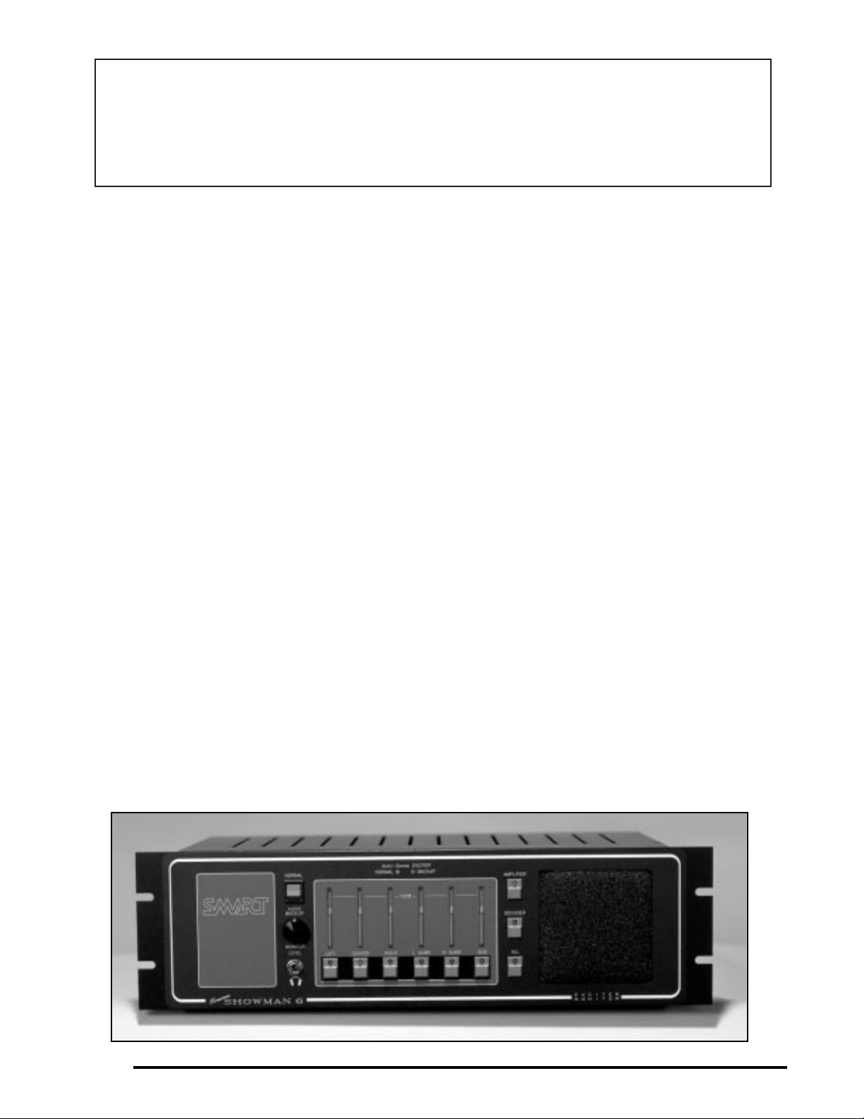
The MN/EXM556 are the finest cinema booth monitors in the industry. All steel construction for strength
and electrical shielding, quick connect P.C. board connections for faster service, easy operating controls and
the many exclusive technical features make the
MN/EXM556 monitors an excellent choice for today’s
cinema sound system needs.
A quick connect socket on the back of the chassis permits the processor to plug directly into the monitor
without wiring. Special plug-in Entrelec connectors on
the back provide a means to mate the MN/EXM556
monitors with any cinema processor or digital system.
A fully regulated computer type exciter switching
supply mounts to the back of the EXM556 chassis and
is easy to remove if repair is ever needed. Also, a low
ripple DC exciter supply backup is included in the
EXM556, along with the “Auto-Sense” automatic
back-up switching circuitry. The MN556 is a monitor
only unit, and has no exciter supply.
FEATURES
MONITOR SECTION
The MN/EXM556 monitors feature full, constant display of the processor or power amplifier outputs,
selectable audio monitoring through the speaker, and
a headphone jack to analyze the sound on each channel for troubleshooting purposes. An active 10 watt
RMS monitor amplifier provides the sound for the
monitor speaker and headphones and also substitutes
for the main power amplifier in an emergency. Front
panel pushbuttons select functions to allow separate
monitoring of each channel of the processor (decoder)
outputs and each channel of the power amplifier outputs (for conventional and biamplified systems)
There are audio inputs for both processor and amplifier outputs on the back of the chassis. Inputs are provided for split-surround systems where one surround
amplifier feeds the left wall speakers, and another
amplifier feeds the right wall surround speakers. The
other inputs are for Left, Center, Right and Subwoofer
channels. Two subwoofer amplifiers may be connected (Sub 1 and Sub 2). Both will be heard simultaneously when Amplifier Subwoofer is selected on the front
panel.
MAIN AMPLIFIER BACKUP
A big feature of the MN/EXM556 is the ability to substitute the built-in 10 watt active monitor for the main
center channel power amplifier if the main amp quits
or becomes distorted.
HEADPHONE JACK
The monitor amplifier drives the internal JBL monitor
speaker and the headphone jack. The jack is a stereo
(ring, tip, and sleeve) type and will work with stereo
headphones. The signal is mono from the single channel monitor amplifier. Any headphone impedance,
from 4 ohms to Hi-Z is usable, although the higher
Installation and Service Manual
MN/EXM556 Cinema Booth Monitor/Exciter
2
Page 3

INSTALLATION & OPERATION
impedance headphones will not be as loud as the low
impedance type.
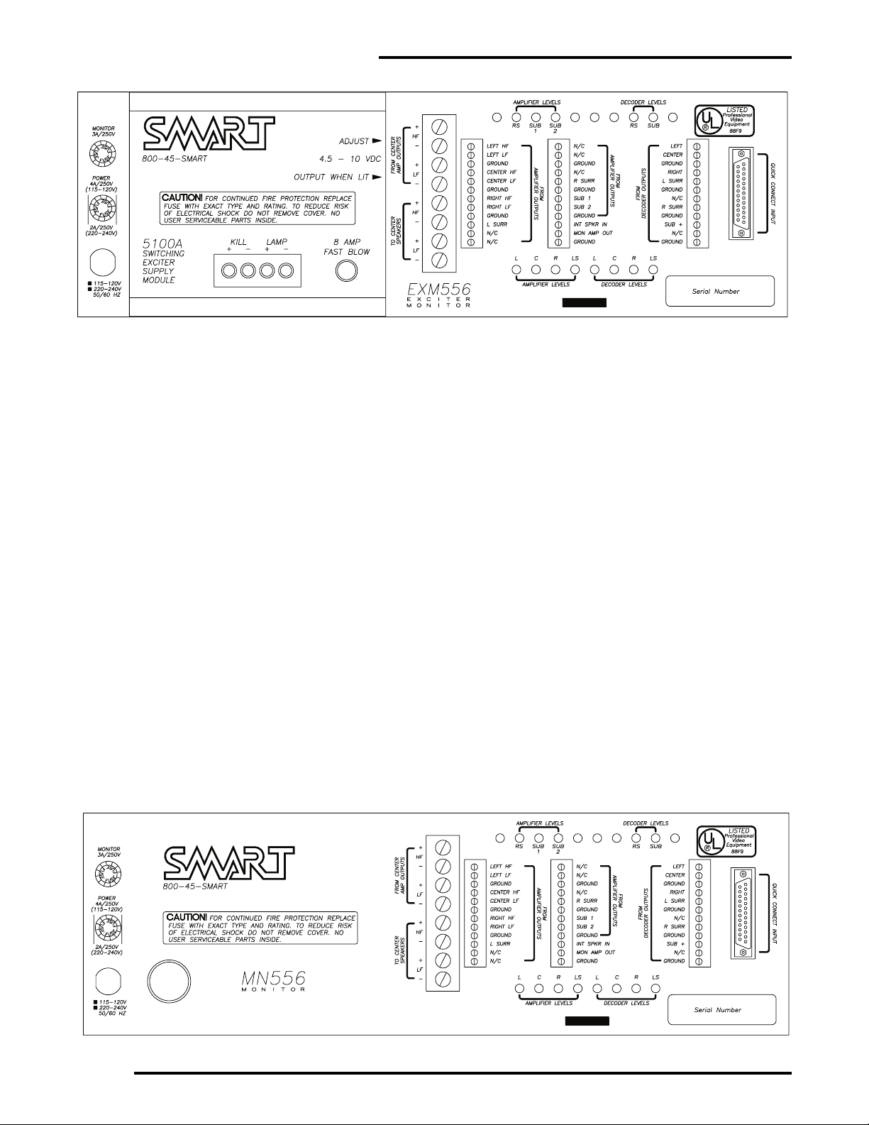
EXCITER SUPPLIES
The MN556 is a monitor only unit, and has no exciter
supply. The EXM556 contains two exciter supplies.
The main supply is a fully regulated switching type
supply that sets new standards for tightness of regulation for line voltages from 109 VAC to 130 VAC. The
output of the supply will not vary more than 1/10 of
1% within the specified AC operating range. Because
the supply switches at 25,000 times a second, hum and
noise are above the audio range. DC output is continuously variable from 4.5 VDC to 10 VDC and is installer
adjusted from the rear of the EXM556. The supply
runs very cool under continuous service and, unlike
conventional “brute force” regulated supplies, does
not contribute a lot of heat to the system. Field
replacement of the regulated supply is easy. The
5100A module may be removed from the back of the
EXM556 without taking the monitor/exciter out of the
rack. Four phillips screws hold the module to the main
chassis. A heavy, high current connector will disconnect the module from the main power source in the
EXM556.
The second exciter supply in the EXM556 is the DC
backup supply. This supply is unregulated. The HI
and LO DC output voltages are selectable by the
installer. The LO setting will produce about 5 volts
and is used with European type exciter bulbs. The HI
setting is used with domestic bulbs. The factory sets
the emergency DC supply to the Hi setting before
shipping unless the product is intended for export and
has a 220/240 power transformer.
The exclusive “Auto Sense” circuit in the EXM556
monitors the output of the regulated main supply. In
the event of a failure of the main supply, or if the supply is removed, the “Auto Sense” comparator will
automatically switch the exciter lamp to the internal
backup DC supply. The operator LED indicator on the
front panel will switch from the NORMAL position to
the BACKUP mode and begin blinking. This indication tells the operator that the exciter is in emergency
backup and the sound engineer should be notified.
Even though both supplies are built of heavy duty
components, the exciter supplies have been designed
for one exciter lamp. The load should not exceed more
than 5 amperes (at any voltage). If two projectors are
used in the booth a relay or switch should be added to
switch between one exciter lamp and the other. Often
this can be a spare set of contacts on the controlling
device that performs other changeover functions.
Make sure the switch or relay contacts can handle the
required exciter lamp current.
KILL CIRCUIT. Another deluxe feature of the 5100A
module is the “kill circuit” that drops the regulated
output exciter voltage to about one volt when the
show is in intermission. This bulb saver feature allows
the bulb to stay in a pre-warmed condition. Bulbs that
are turned on and off during the day will possibly
have a shorter life due to the shock of the high inrush
current into a cold filament. The kill circuit extends
bulb life and is part of the turn-on soft start design of
the 5100A module.
INSTALLATION
INSTRUCTIONS
AMPLIFIER OUTPUTS
The stage speakers may use conventional broadband
power amplifiers with a crossover network at the
loudspeakers, or they may use a biamplified scheme
where there is no crossover at the speaker, but a separate power amplifier feeds the high frequency driver
and another feeds the bass speakers directly. An electronic crossover divides the audio spectrum into two
parts to feed the inputs of the power amplifiers. If you
are using conventional amplifiers, connect each amplifier output to the appropriate input terminals on the
monitor labeled “FROM AMPLIFIER OUTPUTS.” BE
CAREFUL! Most solid state power amplifiers tie the
low output to amplifier ground. Connecting the HOT
terminal to the monitor ground could “fry” the amplifier or monitor input.
Connect conventional amplifiers only to the LF inputs
on the back of the monitor. Even though these inputs
are labeled LF for biamplified systems, they are actually broadband, full range inputs. When connecting a
biamplifier to the monitor inputs, the HF (high frequency) amplifier outputs are connected to the appropriate channel HF inputs on the MN/EXM556 monitor. The LF (low frequency) amplifier outputs are connected to the LF inputs of the monitor. The signals
from the HF and LF amplifiers are summed at a 1:3
ratio inside the monitor so that the proper balance of
HF and LF sound is heard in the monitor speaker and
through the headphone jack. When listening to the
monitor you can determine if a section of the biamplified signal has failed. If the monitor sounds bassy, the
HF amplifier is not producing the HF sounds. If the
monitor sounds shrill, the bass amplifier may have
failed.
3
Page 4
EXM556 STEREO PROCESSOR
CENTER AMP BACKUP
Connect the output of the center channel amplifier to
the terminal strip labeled “FROM CENTER AMP
OUTPUTS.” This is important if you wish to take
advantage of the center amp backup feature that is
part of the MN/EXM556 monitor. Be sure to observe
the correct polarity from the amplifier to the monitor
terminals. A mistake can destroy the monitor or
amplifier. Next, hook the stage speaker to the terminal
strip labeled “TO CENTER SPEAKERS.” Notice that
terminals are provided for HF and LF amplifiers and
speakers for use in biamplified systems. If you are
using conventional amplification, connect only to the
LF terminals.
When a biamplified system is used, the MN/EXM556
will send a signal to both the HF driver and LF
woofer. The HF driver is protected in the backup
mode of operation by a passive network in the
MN/EXM556. The emergency audio backup system is
a valuable feature for your theatre customer.
QUICK CONNECT INPUT
A DB25 computer type connector is provided on the
rear of the chassis for quick connection of a SMART
stereo processor. The pin wiring of this connector conforms to the pin wiring of the THX monitor. Simply
connect a standard serial computer cable to the
SMART processor output plug and connect the other
end to the MN/EXM556 quick connect DB25 input
connector. Signals from the processor will feed the
processor (decoder) inputs of the monitor.
PROCESSOR OUTPUTS
If you are not using the QUICK CONNECT INPUT
connector, then the outputs of a cinema processor
(decoder) may be connected to the “FROM PROCESSOR” input terminals. Usually a ground terminal from
the processor is hooked to a ground on the input to
the monitor. However, a ground connection from
processor to monitor may create ground loops in some
cases, resulting in a hum or buzz. In these cases,
removing the ground connection may improve things.
REMOTE BOOTH SPEAKER
A remote speaker may be used with the MN/EXM556
monitor. Remove the jumper on the connector
between “INT(ernal) SPEAKER IN” and “MON(itor)
AMP OUT”. This will break the connection between
4
Page 5
INSTALLATION & OPERATION
After the MN/EXM556 has been installed and wired
into the system, and after the stereo processor has been
calibrated, the EXM556 input levels should be calibrated so that the display meters represent the level of
each channel of the processor and power amplifiers.
On the rear of the chassis are two sets of calibration
pots. One set is for the processor (decoder) monitoring
and the other is for the amplifiers (conventional or
biamplifiers).
Use the pink noise source that you used earlier to calibrate the SPL level in the auditorium when setting up
the processor and amplifier levels. Select each channel
one at a time, and adjust the appropriate level pot on
the rear of the MN/EXM556 until the display meter
reaches the lower yellow LED. Select the DECODER
button on the front panel to look at the processor outputs and then push the AMPLIFIER button to see each
of the amplifier outputs on the front panel displays.
Again, set each adjust pot to the lower yellow LED.
You will notice that each display will show a moving
dot unless you select that channel on the audio monitor by pushing the appropriate selector button. A
selected channel will show a bar of light to indicate
that it is the information playing through the monitor
speaker. The ALL selector button will sum the Left,
Center, and Right channels, but not the subwoofer or
surround channels. Because the surround channel is
time delayed, a distracting echo would be heard and
the internal speaker and the monitor amplifier.
Connect the external speaker to the “MON AMP
OUT” terminal and GROUND. The monitor Fader on
the front panel will control the volume to the remote
speaker. Both the internal and remote speaker may be
used simultaneously by leaving the jumper in place
and connecting the remote speaker to the “MON AMP
OUT” terminal and “GROUND”, as long as the
remote speaker has an impedance of 8 ohms or more.
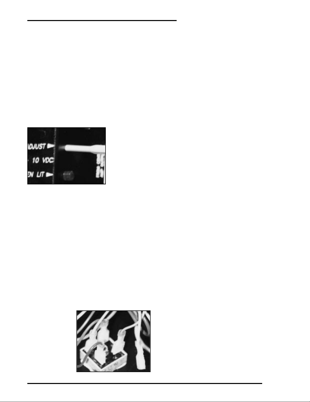
EXCITER SUPPLY
When connecting the exciter supply to the lamp, be
sure to use the proper gauge of wire. Usually a
10AWG or 12AWG is recommended for relatively
short runs.
Measure the lamp
voltage at the
bulb end of the
wire when adjusting the regulated
exciter output
control labeled
“ADJUST.” The
industry recommends that at least 80% of the bulb voltage should be
used for stereo systems. A 10 volt bulb will run well at
8 volts, a 9 volt bulb at 7.2, etc. This gives extended life
to the bulb yet does not cause the filament to cool on
the edges while the center of the filament is hot. If the
bulb voltage is too low, then improper “scanning” of
the full width of the soundtrack will result in distortion during loud sound passages due to the extremes
of the soundtrack not being properly lit.
A “tuning wand” adjustment tool is required to adjust
the 15 turn control that is inside the 5100A module.
This recessed control deters tampering once the lamp
voltage has been properly set.
To change the backup DC exciter supply from a HI to
a LO output, it is necessary to remove the top cover on
the chassis of the EXM556. Make sure power to the
EXM556 has been removed. A diode bridge rectifier is
located on the bottom of the chassis
near the power
toroid transformer,
near the rear of the
chassis. FASTON
push-on connectors
are used to connect
the wires to the terminals of the
bridge. One lead
from the bundle of wires that goes to the bridge is
free. If the GRAY wire (8.5VDC) is connected to one
terminal lug, pull it from the terminal and plug the
GREEN (5.5 VDC) ONTO THE SAME TERMINAL
LUG. This will change the DC backup output voltage
to the opposite selection. You may need pliers to pull
the FASTON because the connection is positive and
tight. The DC backup voltage is set for the HI position
before shipment for domestic bulbs. The LO position
is set for export models.
The terminals labeled KILL on the back of the supply
module may be connected directly to an automation
system that controls the intermission mode of operation in the booth. Shorting the KILL(+) and KILL(-)
terminals will put the supply into the KILL low voltage mode. Releasing the short will allow the bulb to
run at the calibrated voltage. MAKE SURE THE CONTACTS USED TO OPERATE THE KILL CIRCUIT
HAVE NO VOLTAGE ON THEM AND ARE NOT
TIED TO GROUND. A “dry” set of contacts is mandatory, or damage can occur to the transistor input of the
kill circuit.
CALIBRATION
5
Page 6

EXM556 STEREO PROCESSOR
is, therefore, not included in the ALL group.
Before leaving the installation verify that all processor
and amplifier channels are active on the monitor.
Next, pull the fuse on the 5100A regulated exciter supply to confirm that the “Smart Logic” switches automatically to the backup DC exciter supply. Finally, flip
the red AUDIO/BACKUP switch to the backup position to see that the monitor amplifier is feeding the
center stage speaker. Remember, the monitor fader
controls the auditorium level during audio backup.
Also, check the “kill” circuit if it is connected to an
automation system.
OPERATING
INSTRUCTIONS
When you turn the MN/EXM556 monitor on each
day, the SMART LOGIC will default the stereo monitoring to the AMPLIFIER monitoring mode. This
means the outputs of the system power amplifiers are
being displayed on the visual front panel LED indicators. Also, the amplifier outputs are heard on the monitor speaker. Each channel is selected by pushing the
buttons labeled Left, Center, Right, Left Surround,
Right Surround and Subwoofer. When a single channel is selected, the corresponding LED display will
show the sound level on that channel in the form of a
lighted bar and the channel will be heard through the
monitor speaker or headphone jack. Other channels in
the display will show a moving dot. You are able to
see the levels of the six channels, but you will hear
only the selected channel through the speaker. This
feature is valuable in troubleshooting a sound system
channel by channel.
The output of the
stereo processor
may be monitored
by pushing the
DECODER button
on the front panel.
An LED in the
button will indicated that the
DECODER mode
of monitoring is
activated. Again,
you can selectively monitor each
channel from the
output of the
processor.
The ALL button will sum the signals of the Left,
Center, and Right channels and will allow them to be
heard together through the monitor speaker. All three
of the front stage channel LED’s will show a bar of
light to indicate that three channels are being heard
through the speaker. The surround channel will show
a moving dot to indicate the level of the surround
track. Because the surround channel is time delayed, it
is not considered as part of the ALL group.
The FADER on the front panel adjusts the volume
from the built-in monitor amplifier to the internal
speaker. This control does not affect the sound level in
the auditorium, unless the monitor is in AUDIO
BACKUP mode.
The headphone jack is provided in order to closely
analyze the sound quality of each channel. A noisy
booth will cover subtle sounds that would be heard on
headphones. The speaker and amplifier in the
MN/EXM556 have a shaped frequency response that
will penetrate the projector, exhaust fan, and platter
noises normally found in the booth to make listening
more intelligible. The headphone output is smoother
in response. Any stereo headphone with an impedance of 4 ohms to Hi-Z is usable. A mono headphone
will not work.
In the event of a failure of the center amplifier, a center amp backup is built into the MN/EXM556. This
will ensure that the dialog in a movie is not lost. Since
the processor is always sending a signal to the monitor, the amplifier used for the monitor speaker may be
rerouted to the center stage speaker by throwing the
red AUDIO/BACKUP switch on the front panel.
Several things happen when this switch is moved
from the normal position to the backup position. First,
the SMART LOGIC circuits default to the processor
input monitoring (you may have been monitoring the
power amplifiers). Next, the SMART LOGIC sums the
stage channel inputs so that the Left, Center, and
Right processor channels are present at the monitor
amplifier output. Finally, the monitor speaker is disconnected and all of the power is switched to the center stage speaker. This is all accomplished with the
one RED backup switch. The monitor fader control is
now used to adjust level in the auditorium. Since most
stage speakers are very high efficiency devices, 10
watts is plenty to keep sound in the center channel
speaker. For center amp backup to work properly, the
center amp and speaker MUST be connected to the
monitor properly (see CENTER AMP BACKUP in the
INSTALLATION INSTRUCTIONS section).
6
Page 7

SCHEMATICS
EXM/MN556 Display Board (0556x300) – pages 8-9
EXM/MN556 Logic board (0556x320) – pages 10-11
EXM/MN556 Backplane Board (0554x390) – pages 12-13
7
INSTALLATION & OPERATION
Page 8

EXM556 STEREO PROCESSOR
8
Page 9

INSTALLATION & OPERATION
9
Page 10

EXM556 STEREO PROCESSOR
10
Page 11

INSTALLATION & OPERATION
11
Page 12

EXM556 STEREO PROCESSOR
12
Page 13

INSTALLATION & OPERATION
13
Page 14

EXM556 STEREO PROCESSOR
14
Page 15

INSTALLATION & OPERATION
15
Page 16

EXM556 STEREO PROCESSOR
16
Page 17

INSTALLATION & OPERATION
17
 Loading...