

Order no. 6522 0225 13
Part no. 453 584 81 09
Edition A-2018
4535848109
É4535848109)ËÍ
>> Operator's Manual
smart fortwo coupe and smart fortwo cabrio electric drive
www.smart.com smart - A Daimler brand
smart fortwo coupe and smart fortwo cabrio electric drive Operator's Manual

Symbols in the Operator's Manual
Registered trademarks:
R
Android™ is a registeredtrademarkof Google, Inc.
R
Android Auto™ is a registered trademark of
Google, Inc.
R
Apple®iOS and iPod®are registered trademarks of Apple, Inc.
R
Bass boost arkamys®is a registered trademark of Arkamys.
R
Bluetooth®is a registered trademark of
Bluetooth SIG Inc.
R
ESP®is a registered trademark of
Daimler AG.
R
IQ Routes™ is a registered trademark of
TomTom International B.V.
R
MirrorLink™ is a registered trademark of
the Car Connectivity Consortium.
The following symbols are used in this Operator's Manual:
WARNING
G
Warning notes make you aware of dangers
which could pose a threat to your health or
life, or to the health and life of others.
Environmental note
H
Environmental notes provide you with
information on environmentally aware
actions or disposal.
Publication details
Internet
Further information about smart vehicles
and about Daimler AG can be found on the
following websites:
http://www.smart.com
http://www.daimler.com
Editorial office
Daimler AG: not to be reprinted, translated
or otherwise reproduced, in whole or in part,
without written permission from Daimler AG.
Vehicle manufacturer
Daimler AG
Mercedesstrae 137
70327 Stuttgart
Germany
Notes on material damage alert you to
!
dangers that could lead to damage to your
vehicle.
Practical tips or further information that
i
could be helpful to you.
X Instructions that must be followed.
X Several consecutive symbols indicate an
instruction with several consecutive steps.
(Y page) Further information on a topic
YY A warning or an instruction that is con-
tinued on the next page.
Display text:
Display text in the instrument cluster display, the smart Audio-System or the smart Media-System.
As at 20.01.2017

About this Operator's Manual
We urge you to read this Operator's Manual
carefully and familiarize yourself with the
vehicle before driving. For your own safety
and a longer vehicle life, follow the instructions and warning notices in this Operator's
Manual. Ignoring them could result in damage to the vehicle or personal injury to you or
others.
This Operator's Manual provides information
on the most important functions of your
vehicle.
The equipment or product designation of
your vehicle may vary depending on:
R
Model
R
Order
R
Country specification
R
Availability
The illustrations in this Operator's Manual
show a left-hand-drive vehicle. On righthand-drive vehicles, the layout of components and controls differs accordingly.
smart reserves the right to introduce
changes in the following areas:
R
Design
R
Equipment
R
Technical features
The equipment in your vehicle may therefore
differ from that shown in the descriptions
and illustrations.
Integral parts of the vehicle include:
R
Operator's Manual
R
Maintenance Booklet
R
Equipment-dependent Supplements
Keep copies of the documents in the vehicle
at all times. If you sell the vehicle, always
pass all documents on to the new owner.
Your Operator's Manuals:
Digital on the Internet
The Operator's Manual on the Internet
provides you with convenient access to
all of the information relevant to your
vehicle and multimedia system. It also
offers helpful animations, exciting
background information and various
search options.
Digital as an app
Using the smart guides app, you can call
up all of the information relevant to
your vehicle and multimedia system
online on your phone or as a download
regardless of the status of your network
connection. Available for smartphones
and tablets.
Please note that the smart guides app may
not currently be available in your country.
4535848109
É4535848109)ËÍ

2
Contents
Index ......................................................... 4
Introduction ........................................... 19
Protection of the environment ............. 19
smart genuine parts .............................. 19
Warranty for the smart Audio-Sys-
tem and smart Media-System .............. 20
Vehicle equipment ................................. 20
Service and vehicle operation .............. 20
Operating safety .................................... 21
QR codes for rescue card .......................24
Data stored in the vehicle .................... 24
Information on copyright .....................26
At a glance .............................................. 27
Dashboard ............................................... 27
Multifunction steering wheel .............. 28
Center console with drawer .................. 29
Overhead control panel .........................30
Door control panel .................................31
Displays shown in the instrument
cluster and the display .........................32
Safety ...................................................... 33
Activating and deactivating the
panic alarm ............................................ 33
Occupant safety ..................................... 33
Children in the vehicle ......................... 42
Pets in the vehicle ................................. 45
Driving safely ........................................ 45
Entering and setting up ........................ 48
Understanding functions of the
SmartKey ................................................. 48
Opening the door ................................... 48
Correct driver's seat position ............... 48
Adjusting the seats ............................... 49
Adjusting the mirrors ............................ 50
Driving ..................................................... 52
Starting the engine ............................... 52
Pulling away .......................................... 52
Automatic transmission ........................ 54
Using the turn signals .......................... 55
Acoustic presence indicator ................. 55
Driving economically ............................ 56
Braking correctly ................................... 59
Driving on wet roads ............................. 60
Winter driving ........................................ 60
Using cruise control .............................. 60
Charging the high-voltage battery ..... 61
Ensuring good visibility ........................ 69
Switching on the lighting ..................... 69
Using the interior lighting ................... 70
Using the windshield wiper ................. 71
Folding the sun visor to the side ......... 72
Feeling comfortable in the vehicle
interior .................................................... 73
Locking and unlocking the doors
from the inside ....................................... 73
Understanding the reversing fea-
ture .......................................................... 73
Opening and closing the windows ....... 74
Using the soft top (smart fortwo
cabrio) ..................................................... 75
Installing and removing the wind
screen (smart fortwo cabrio) ................ 78
Operating the climate control sys-
tem ........................................................... 78
Activating/deactivating the seat
heating and steering wheel heating ... 80
Using the accessories ........................... 81
Parking and getting out ........................ 83
Parking .................................................... 83
Using the rear view camera .................. 83
Locking the vehicle ............................... 84
Arming and disarming the anti-
theft alarm system ................................ 84
Operating the on-board computer ....... 85
Overview of the on-board computer ... 85
Calling up displays ............................... 85
Setting values ........................................ 87

Contents
3
Using the smart Audio-System ............. 89
Operating and setting the smart
Audio-System .........................................89
Listening to the radio ........................... 91
Using a mobile phone ............................ 92
Operating external data carriers ......... 94
Using the smart Media-System ............ 96
Operating and setting up the smart
Media-System ........................................ 96
Listening to the radio .......................... 100
Calling up electric drive displays ..... 101
Using a mobile phone .......................... 102
Connecting and operating external
data carriers ......................................... 106
Viewing images .................................... 108
Video playback .....................................109
Using the navigation system ............. 109
Managing apps ..................................... 119
Loading and stowing ............................ 121
Stowing small objects ......................... 121
Stowing luggage and large objects ... 122
Using the trunk partition ................... 124
Removing/installing the charging
cable bag ............................................... 125
Observing the tire and loading
information ........................................... 126
Maintenance and care .......................... 129
Useful information ...............................129
Removing/installing the subwoofer .. 129
Opening and closing the service
cover ...................................................... 129
Checking and adding service prod-
ucts ........................................................ 131
Checking wheels and tires .................. 132
Obtaining information on tires .......... 133
Changing a wheel ................................ 139
Using the tire pressure monitor ........ 143
Checking the tire pressures ............... 144
Using winter tires ................................ 147
Using snow chains ...............................147
Changing the window wiper blades .. 148
Cleaning the vehicle ............................ 149
Observing service due dates .............. 153
Parking the vehicle for a long
period .................................................... 153
Dealing with accidents and break-
downs .................................................... 154
Securing the vehicle in the event of
an accident or a breakdown ...............154
Removing the vehicle tool tray .......... 155
Sealing tires using the TIREFIT kit ... 155
Towing the vehicle .............................. 157
Manually releasing the selector
lever lock .............................................. 159
Replacing the bulbs ............................ 160
Changing fuses ..................................... 162
Replacing the SmartKey battery ........ 163
Opening a door with the emergency
release ................................................... 164
Locking the doors in an emergency .. 164
Practical advice .................................... 166
Notes on display messages ................ 166
Locking and unlocking ........................ 166
Visibility, occupants, air bags ........... 168
Engine, brakes, transmission ............. 170
Charging process ................................. 172
Driving safety systems ....................... 175
Driver assistance systems .................. 180
Battery, lights, heating ....................... 181
smart Audio-System and smart
Media-System ...................................... 183
Technical data ...................................... 185
Obtaining technical data .................... 185
Reading out vehicle data .................... 185
Service products .................................. 186
Climate control system refrigerant ... 186
Bulb types ............................................. 187
Fuse allocation ..................................... 188
Radio type approvals for the tire
pressure monitor ................................. 190
Installing two-way radios and
mobile phones ...................................... 190

Index
4
1, 2, 3 ...
12 V socket
see Socket (12 V)
A
ABS (Anti-lock Braking System)
Display message ............................ 175
Function/notes ................................. 45
Warning lamp (yellow) .................. 175
Acceleration
see Kickdown
Acoustic presence indicator
Function/notes ................................. 55
Air bag
Installation locations ...................... 37
Limited protection ........................... 38
Overview ........................................... 37
Air bags
Deployment ...................................... 34
Front air bag (driver, front
passenger) ........................................ 37
Head bag ........................................... 37
Knee bag ........................................... 37
PASSENGER AIR BAG indicator
lamps ................................................. 39
Protection provided ......................... 38
Side impact air bag ......................... 37
Window curtain air bag .................. 37
Air distribution
Setting (automatic climate con-
trol) .................................................... 79
Air pressure
see Tire pressure
Air vents
Important safety notes ................... 80
Setting ............................................... 80
Air-recirculation mode
Switching on/off (automatic
climate control) ................................ 79
Alarm
Anti-theft alarm system ................. 84
Switching off .................................... 84
Ambient lighting
Setting the brightness .................... 88
Switching on/off .............................. 88
Android Auto™
Using ............................................... 105
Animals
see Pets in the vehicle
Anti-entrapment feature
see Reversing feature
Anti-lock Braking System
see ABS (Anti-lock Braking System)
Anti-skid chains
see Snow chains
Anti-theft alarm system
Switching off the alarm .................. 84
Switching on/off .............................. 84
Apps
Displaying/calling up ................... 120
General notes ................................. 119
Installing ........................................ 119
Ashtray .................................................... 81
Audio-System
Connecting a mobile phone ............ 92
Connecting Bluetooth
devices .............................................. 95
Connecting external audio
equipment (AUX) .............................. 95
Operating .......................................... 89
Operating the radio ......................... 91
Operating via the mobile phone .... 90
Overview ........................................... 89
Setting the time ............................... 90
Smartphone bracket ........................ 90
System settings ............................... 90
Troubleshooting .............................183
Using external devices ................... 89
Volume/sound settings ................... 91
Warranty ...........................................20
Authorized workshop
see Qualified specialist workshop
Automatic car wash (care) ................... 149
Automatic climate control
Activating/deactivating air-
recirculation mode .......................... 79
Cooling with air dehumidifica-
tion .................................................... 79
Defrosting the rear window ............ 79
Defrosting the windshield .............. 79
Increasing/decreasing
blower speed .................................... 79
Setting air distribution .................. 79
Setting the temperature .................79
Switching on/off .............................. 78
®
audio
the

Index
5
Windows fogged up ......................... 79
Automatic headlamp mode .................... 69
Automatic transmission
Engaging neutral ............................. 55
Engaging reverse gear .................... 55
Engaging the park position ............ 55
Important safety notes ................... 54
Kickdown .......................................... 55
Manually releasing the selector
lever lock ........................................159
Pulling away .................................... 52
Starting the engine ......................... 52
Transmission positions .................. 55
AUX jack
Audio-System ................................... 89
Media-System .................................. 96
B
Battery
Display message ............................ 181
Battery
see High-voltage battery
Battery (SmartKey)
Important safety notes ................. 163
Replacing ........................................ 163
Battery (vehicle)
see High-voltage battery
Belt
see Seat belt
Belt warning ........................................... 37
Blower speed
Increasing or decreasing (auto-
matic climate control) ..................... 79
Bluetooth
Brake fluid
®
Activating the mobile phone
(Audio-System) ................................ 92
Activating the mobile phone
(Media-System) .............................. 102
Authorizing the function for the
mobile phone (Audio-System) ........ 92
Connecting a device (Media-
System) ........................................... 107
Operating (Audio-System) .............. 95
Switching on/off (Media-Sys-
tem) ................................................. 102
Display message ............................ 171
Brake force distribution
see EBD (electronic brake force
distribution)
Brake lamp
Replacing bulbs .............................161
Brake lamps
Display message ............................ 182
Brakes
ABS ..................................................... 45
Braking on downhill gradients ...... 59
Braking on wet road surfaces ........ 59
EBD ..................................................... 47
Important safety notes ................... 59
Limited braking performance
on salt-treated roads ...................... 59
Parking brake ................................... 53
Riding tips ........................................ 59
Warning lamp ................................. 171
Breakdown
Towing away .................................. 157
see Flat tire
C
Car
see Vehicle
Car wash
see Care
Care
Car wash .......................................... 149
Carpets ............................................ 152
Cleaning the interior ..................... 151
Cleaning the roof lining (smart
fortwo coupe) .................................. 152
Display ............................................ 151
Exterior ...........................................149
Exterior lights ................................ 151
High-voltage battery ...................... 63
Interior ............................................ 151
Notes ............................................... 149
Paint ................................................ 151
Plastic trim ..................................... 152
Power washer ................................. 149
Roof lining ...................................... 151
Seat belt .......................................... 152
Seat cover ....................................... 152
Selector lever ................................. 152
Sensors ............................................ 150

Index
6
Soft top system .............................. 151
Steering wheel ...............................152
Trim pieces ..................................... 153
Washing by hand ........................... 149
Wheels ............................................. 150
Windows .......................................... 150
Wiper blades ................................... 150
Center console
Overview ........................................... 29
Central locking
Automatic locking ............................ 73
Locking/unlocking (SmartKey) ...... 84
Changing bulbs
see Replacing bulbs
Changing the route
Navigation ...................................... 113
Charge current
Setting (charging cable) ................. 65
Charge level display .............................. 57
Charging cable
Connecting ........................................ 66
Controls ............................................. 65
Display message ............................ 172
Removing .......................................... 67
Storing ..............................................68
Warming up ...................................... 64
Charging cable bag
Removing/fitting ...........................125
Charging current
Display messages .......................... 172
Child seat
Forward-facing restraint sys-
tem ..................................................... 44
On the front-passenger seat .......... 44
Rearward-facing restraint sys-
tem ..................................................... 44
Top Tether ........................................ 43
Children
Restraint systems ............................ 42
Special seat belt retractor .............. 43
Cigarette lighter ..................................... 81
Cleaning
see Care
Climate control
Automatic climate control .............. 78
General notes ................................... 78
Refrigerant ..................................... 186
Refrigerant filling capacity ......... 187
Setting the air vents ....................... 80
Clock
Setting the time (Media-Sys-
tem) ................................................... 98
Cockpit
Overview ...........................................27
COMAND display
Cleaning .......................................... 151
Connectivity manager .......................... 120
Consumption details
Calling up (Media-System) ........... 102
Controlling speed
see Cruise control
Coolant
Checking the coolant level and
adding coolant ............................... 131
Important safety notes ................. 131
Cooling
see Climate control
Cooling with air dehumidification
Automatic climate control .............. 79
Copyright ................................................ 26
Cornering light function ........................ 70
Cover (front)
see Service cover
Crosswind Assist ..................................... 46
Cruise control
Activating ......................................... 61
Buttons .............................................. 61
Calling up the speed last stored
Canceling cruise control ................. 61
Deactivating ..................................... 61
Display message (color display) .. 181
Function/notes ................................. 60
General notes ................................... 60
Important safety notes ................... 60
Increasing/decreasing the
speed ................................................. 61
Storing and maintaining cur-
rent speed ......................................... 61
Cup holder
Center console ................................ 121
Important safety notes ................. 121
Customer Assistance Center (CAC) ........ 24
Customer Relations Department ........... 24
.... 61

Index
7
D
Dashboard
see Cockpit
Data
see Technical data
Data carriers
see External data carriers
Data sharing
Managing ........................................ 120
Daytime running lamp mode
see Daytime running lights
Daytime running lights ......................... 69
Dealership
see Qualified specialist workshop
Declarations of conformity ....................22
Diagnostics connection .......................... 22
Digital speedometer
Displaying ........................................ 88
Display
Color .................................................. 85
Display message
Color display .................................... 87
Display messages
General notes ................................. 166
Distance warning function
Function/notes ................................. 45
Warning lamp ................................. 180
Door
Unlocking (SmartKey) ..................... 48
Doors
Automatic locking (switch) ............ 73
Central locking/unlocking
(SmartKey) ........................................ 84
Control panel .................................... 31
Display message ............................ 167
Emergency locking ........................ 165
Emergency unlocking ................... 164
Opening (from inside) ..................... 73
Drinking and driving .............................. 53
Driver's door
see Doors
Driver's seat
see Seat
Driving economically
eco score display ............................. 57
General notes ................................... 56
Driving noise
see Acoustic presence indicator
Driving safety system
Crosswind Assist .............................. 46
Limits of the driving safety
systems ............................................. 45
Driving safety systems
ABS (Anti-lock Braking System) .... 45
Distance warning function ............. 45
EBD (electronic brake force dis-
tribution) .......................................... 47
®
(Electronic Stability Pro-
ESP
gram) ................................................. 46
ETS (Electronic Traction Sys-
tem) ................................................... 46
Driving systems
Cruise control ................................... 60
Driving tips
Brakes ................................................ 59
Downhill gradient ............................ 59
Drinking and driving ...................... 53
Driving in winter ............................. 60
Driving on flooded roads ................ 60
Driving on wet roads ....................... 60
Hydroplaning ................................... 60
Icy road surfaces ............................. 60
Limited braking efficiency on
salted roads ...................................... 59
Pulling away .................................... 52
see Driving economically
Dynamic handling control system
®
see ESP
(Electronic Stability
Program)
E
EBD (electronic brake force distribution)
Function/notes ................................. 47
EBD (Electronic Brake-force Distribution)
Indicator lamp ................................ 175
ECO mode
Switching on/off .............................. 56
eco score
Calling up ......................................... 57
Comparing a trip .............................. 58
Display (color display) .................... 57

Index
8
Evaluating the current trip ............ 58
Function/notes ................................. 57
Resetting data .................................. 58
Saving a trip ..................................... 58
Electronic Brake-force Distribution
see EBD (electronic brake force
distribution)
Electronic Stability Program
®
see ESP
(Electronic Stability
Program)
Electronic Traction System
see ETS (Electronic Traction System)
Emergency release
Driver's door ................................... 164
Vehicle ............................................ 164
Emergency Tensioning Devices
Activation .........................................34
Energy
Displaying the current con-
sumption (color display) ................ 86
Energy consumption
High-voltage battery ...................... 63
Energy flow display
Calling up (Media-System) ........... 101
Color display .................................... 86
Engine
Starting problems .......................... 170
Starting the engine with the
SmartKey .......................................... 52
Switching off .................................... 83
Engine electronics
Notes .................................................21
Entering a destination
Navigation ...................................... 110
Environmental protection
High-voltage battery ...................... 19
®
(Electronic Stability Program)
ESP
Crosswind Assist .............................. 46
Display message ............................ 176
General notes ................................... 46
Important safety information ........ 46
Warning and indicator lamps ......176
ETS (Electronic Traction System) ......... 46
Exterior lighting
Cleaning .......................................... 151
see Lights
Exterior mirrors
Adjusting .......................................... 51
Out of position (troubleshoot-
ing) .................................................. 168
External audio equipment (AUX)
Connecting (Audio-System) ........... 95
External data carriers
Connecting (Audio-System) ...........
89
Connection (Media-System) ......... 107
Operating (Audio-System) .............. 94
Operation (Media-System) ........... 107
F
Factory settings
Resetting (Media-System) .............. 98
Favorites
Creating (Media-System) .............. 100
Managing (Media-System) ........... 100
Fender
see Front wheel arch
Flat tire
Preparing the vehicle .................... 154
TIREFIT kit ...................................... 155
Floormats ................................................ 82
Fog lamps
Switching on/off .............................. 70
Fording
On flooded roads .............................. 60
Forward collision warning
Display message ............................ 180
Frequencies
Mobile phone .................................. 190
Two-way radio ............................... 190
Front air bag ...........................................37
Front cover
see Service cover
Front wheel arch
Removing/installing the cover .... 160
Front wheel arch cover
Installing/removing ...................... 160
Front-passenger front air bag
deactivation system
PASSENGER AIR BAG indicator
lamps ................................................. 39
Status indicator ............................... 39
Front-passenger seat
Folding down .................................. 124

Index
9
Front-passenger seat
see Seat
Frontal area cover
see Service cover
Fuses
Allocation chart ............................. 188
Before changing ............................. 163
Dashboard fuse box ....................... 163
Important safety notes ................. 162
Opening the fuse box ..................... 163
G
Genuine parts ......................................... 19
Glove box ............................................... 122
H
Hand brake
see Parking brake
Hands-free system
see Mobile phone
Hazard warning lamps
Switching on/off ............................ 154
Head bags ................................................ 37
Headlamps
see Automatic headlamp mode
Heating
see Climate control
High beam flasher .................................. 69
High-beam headlamps
Replacing bulbs ............................. 160
Switching on/off .............................. 69
High-voltage battery
Battery care ...................................... 63
Charge level display ........................ 56
Charging (charging station) ........... 67
Charging (mains socket) ................. 65
Charging (wallbox) .......................... 67
Charging cable warming ................. 64
Condition of charge ......................... 56
Cruise range ..................................... 63
Discharged battery .......................... 63
Display message ............................ 181
Energy consumption ....................... 63
Important safety notes ................... 61
Indicator lamp (vehicle socket) ..... 64
Method of operation ........................ 63
Outside temperatures ...................... 63
Problems with the charging
process ............................................ 172
Protective equipment ...................... 64
READY indicator ............................. 181
Terms of use ..................................... 64
Vehicle socket .................................. 64
Warning and indicator lamps ...... 181
High-voltage electrical system
Automatic switch-off ...................... 23
Danger of electric shock ................. 23
Operating safety .............................. 23
Vehicle fire ....................................... 24
Home address
Entering and saving ...................... 111
Home address (navigation)
see Home address
Hydroplaning .......................................... 60
I
i-Traffic
Traffic reports ................................ 101
Ignition lock
see Key positions
Image
Playback (Media-System) ............. 108
Immobilizer ............................................. 84
Indicator and warning lamps
Battery ............................................ 181
Indicator lamps
see Warning and indicator lamps
Instrument cluster
Overview ........................................... 32
Warning and indicator lamps ........ 32
Instrument cluster lighting
Adjusting .......................................... 88
Instrument lighting
see Instrument cluster lighting
Interior lighting ..................................... 70
Replacing bulbs ............................. 162
Setting the ambient lighting ......... 88
Setting the ambient lighting
(color display) .................................. 71
Switching on/off .............................. 70
Intermittent wiping ............................... 71

10
Index
J
Jack
Using ............................................... 140
K
Key
Position in the ignition lock .......... 52
Keyboard
Changing (Media-System) .............. 98
Kickdown .................................................55
Knee bag .................................................. 37
L
Lamps
see Warning and indicator lamps
Language
Selecting (Media-System) .............. 98
Language (on-board computer) ............ 88
License plate lamp
Changing bulbs .............................. 162
Lighting
Setting the ambient lighting ......... 88
Lights
Automatic headlamp mode ............. 69
Cornering light function ................. 70
Display message ............................ 182
Fog lamps ......................................... 70
Hazard warning lamps .................. 154
High beam flasher ........................... 69
High-beam headlamps .................... 69
Light switch ..................................... 69
Low-beam headlamps ..................... 69
Parking lamps .................................. 70
Rear fog lamp ................................... 70
Turn signals ..................................... 55
see Interior lighting
see Replacing the bulbs
Loading guidelines ...............................122
Locking
see Central locking
Locking (doors)
Automatic ......................................... 73
Emergency locking ........................ 165
From inside (central locking
button) ..............................................73
Loudspeaker
see Subwoofer
Low-beam headlamps
Replacing bulbs ............................. 160
Switching on/off .............................. 69
M
M+S tires (winter tires) ........................ 147
Making a call
Media-System ................................ 103
Malfunction message
see Display message
Manually releasing the selector
lever lock (automatic transmission) ... 159
Media system
Creating favorites .......................... 100
System menu .................................... 98
System settings ............................... 98
Volume/tone settings ...................... 99
Media-System
Buttons on the multifunction
steering wheel ................................. 96
Calling up menus ............................. 97
Changing the on-screen key-
board ................................................. 98
Connectivity manager ................... 120
Consumption details ...................... 102
Controls ............................................. 96
Data connectivity .......................... 119
Display settings ............................... 98
eco score ........................................... 57
Enabling data sharing .................. 120
Energy flow display ...................... 101
Home screen ..................................... 97
Image playback .............................. 108
Installing apps ............................... 119
Navigation menu ........................... 109
Navigation system ......................... 109
Operating the radio ....................... 100
Overview ........................................... 96
Problem solving ............................. 183
Selecting the home screen dis-
play ................................................... 98
Selecting the language ................... 98
Setting the time ............................... 98
Setting warning tones ..................... 99
Status and information ................... 98

Index
11
Switching on/off .............................. 97
Video playback ...............................109
Warranty ........................................... 20
Message memory (color display) .......... 87
Mirror
see Exterior mirrors
MirrorLink™
Using ............................................... 104
Mirrors
see Rear-view mirror
Mobile phone
Automatically downloading
data (Media-System) ..................... 103
Connecting (Audio-System) ........... 92
Connecting (Media-System) ......... 102
Frequencies .................................... 190
Installation ..................................... 190
Loading and updating the
phone book (Audio-System) ........... 93
Setting the sound (Audio-Sys-
tem) ................................................... 93
Transmission output (maxi-
mum) ................................................ 190
Using Android Auto™ .................... 105
Using MirrorLink™ ........................ 104
Using the telephone (Media-
System) ........................................... 103
Using voice control (Audio-
System) ............................................. 94
Using voice control (Media-
System) ........................................... 106
Model series
see Vehicle identification plate
Mounting wheels
Mounting a new wheel .................. 142
Preparing the vehicle .................... 140
Raising the vehicle ........................ 140
Removing a wheel .......................... 140
Securing the vehicle against
rolling away ................................... 154
Multi-functional seat
see Seat
Multifunction steering wheel
Overview ........................................... 28
N
Navigation
Alternative route ........................... 113
Changing the route ........................ 113
Current location .............................116
Destination memory ...................... 111
Displaying the reachability
map .................................................. 116
Entering a charging station as a
destination ..................................... 111
Entering a destination .................. 110
Entering a destination by
address ............................................ 110
Entering a destination using
geo-coordinates .............................111
Entering a destination using
the map ...........................................110
Entering a point of interest .......... 111
Entering/saving your home
address ............................................ 111
Reading map data .......................... 109
Route details .................................. 113
Selecting a destination from the
list of last destinations ................. 111
Setting route planning .................. 114
Setting the voice ............................ 118
Starting ...........................................109
Starting route calculation ............ 112
Switching announcements
on/off ............................................... 114
System settings .............................118
TomTom Services ........................... 116
Traffic information ........................ 115
Troubleshooting .............................183
Way points ...................................... 113
O
Occupant safety
Air bags ............................................. 37
Belt warning ..................................... 37
Children in the vehicle ................... 42
PASSENGER AIR BAG indicator
lamps ................................................. 39
Pets in the vehicle ........................... 45
Restraint system .............................33
Restraint system warning lamp .... 33
Seat belt ............................................ 35

12
Index
On-board computer
Calling up displays (color dis-
play) .................................................. 85
Important safety notes ................... 85
Operation .......................................... 85
Overview ........................................... 85
Selecting the language ................... 88
Setting/resetting values (color
display) .............................................87
On-board diagnostic interface
see Diagnostics connection
On-screen keyboard
Changing (Media-System) .............. 98
Operating safety
Declaration of conformity ............... 22
High-voltage electrical system ..... 23
Operating system
see On-board computer
Operator's Manual
Vehicle equipment ........................... 20
Outside temperature display ................ 85
Setting the units .............................. 88
Outside temperatures
High-voltage battery ...................... 63
Overhead control panel ......................... 30
Overvoltage protection
High-voltage battery ...................... 64
Problem (malfunction) .................. 169
Pets in the vehicle ................................. 45
Point of interest
Entering .......................................... 111
Power display ......................................... 57
Power windows
see Side windows
Pre-entry climate control and
charging
Color display .................................... 87
Pre-entry climate control at departure time
Setting departure time .................... 79
Smart-Charging ............................... 79
Protection against theft
Anti-theft alarm system ................. 84
Protection of the environment
General notes ................................... 19
Pulling away
General notes ................................... 52
Hill start assist ................................ 54
Q
QR code
Rescue card ...................................... 24
Qualified specialist workshop ............... 23
P
Paint code number ............................... 185
Paintwork (cleaning instructions) ...... 151
Panic alarm ............................................. 33
Park brake
see Parking brake
Parking .................................................... 83
Engaging park position .................. 55
Important safety notes ................... 83
Parking brake ................................... 53
Rear view camera ............................. 83
Parking brake
Display message ............................ 171
General notes ................................... 53
Warning lamp ................................. 171
Parking lamps
Switching on/off .............................. 70
PASSENGER AIR BAG
Indicator lamps ................................ 39
R
Radio
Display mode .................................. 100
i-Traffic (traffic reports) .............. 101
Operating (Audio-System) .............. 91
Operation (Media-System) ........... 100
Radio text
Displaying (Audio-System) ............ 92
Displaying (Media-System) .......... 101
Radio type approvals
Tire pressure monitor ................... 190
Radio-wave reception/transmission in the vehicle
Declaration of conformity ............... 22
Rain and light sensor (display mes-
sage) ...................................................... 182
Rain sensor ............................................. 71
Range
High-voltage battery ...................... 63
Reading lamp .......................................... 70

Index
13
Rear fog lamp
Replacing bulbs ............................. 161
Switching on/off .............................. 70
Rear lamp
Replacing bulbs ............................. 161
Rear soft top
Closing ............................................ 123
Opening ........................................... 123
Rear window defroster
Defrosting the rear window
(automatic climate control) ............79
Rear window wiper
Automatic rear window wiper
when backing up ............................. 72
Replacing the wiper blade ............148
Switching on/off.............................. 72
Rear-view mirror .................................... 50
Anti-glare (manual) ........................ 50
Dipping (automatic) ........................ 50
Recycling
see Protection of the environment
Refrigerant (air-conditioning system)
Important safety notes ................. 186
Replacing bulbs
Brake lamp ...................................... 161
High-beam headlamps .................. 160
Important safety notes ................. 160
Installing/removing the cover
(front wheel arch) .......................... 160
Interior lighting ............................ 162
LED ................................................... 161
License plate lamp ........................ 162
Low-beam headlamps ................... 160
Overview of bulb types ................. 187
Rear fog lamp ................................. 161
Rear lamp ........................................ 161
Reversing lamp .............................. 161
Turn signal lamp (rear) ................. 161
Replacing the bulb
Turn signal lamp (front) ............... 160
Rescue card ............................................. 24
Restraint system
Display message ............................ 169
Function during an accident .......... 34
Limited protection ........................... 33
Operational readiness ..................... 33
Protection provided ......................... 33
System self-test .............................. 33
Warning lamp ................................. 169
Warning lamp (function) ................ 33
Restraint systems
Malfunction ...................................... 33
Reverse gear
Engaging (automatic transmis-
sion) ................................................... 55
Reversing feature
Side windows .................................... 73
Reversing lamp
Replacing bulbs ............................. 161
Roadside Assistance (breakdown) ........ 20
Roof lining and carpets (cleaning
guidelines) ............................................ 152
S
Safety
Children in the vehicle ................... 42
see Occupant safety
see Operating safety
Safety system
see Driving safety system
SD card
Connecting (Media-System) ......... 107
Reading map data .......................... 109
SD card slot ....................................... 96
Seat
Correct driver's seat position ......... 48
Folding the front-passenger
seat down ........................................ 124
Seat belt
Limited protection ........................... 35
Protection provided ......................... 35
Seat belts
Cleaning .......................................... 152
Fastening .......................................... 36
Releasing .......................................... 36
Warning lamp ................................. 168
Warning lamp (function) ................ 37
Seat heating ............................................ 80
Seats
Adjusting (manually) ...................... 49
Cleaning the cover ......................... 152
Important safety notes ................... 49
Switching seat heating on/off ........ 80

14
Index
Selector lever
Cleaning .......................................... 152
Selector lever
see Automatic transmission
Sensors (cleaning instructions) .......... 150
Service appointment
Display message ............................ 172
Service Center
see Qualified specialist workshop
Service cover ........................................ 129
Service display
Calling up (color display) ............... 87
Service products
Brake fluid ...................................... 186
Coolant (engine) ............................. 131
Important safety notes ................. 131
Refrigerant (air-conditioning
system) ............................................ 186
Washer fluid ................................... 186
Side bars
Closing the stowage well ................ 77
Mounting .......................................... 77
Removing .......................................... 76
Stowing .............................................76
Side impact air bag ................................ 37
Side turn signal lamps
Replacing bulbs ............................. 161
Side windows
Cleaning .......................................... 150
Important safety information ........ 74
Opening/closing ............................... 74
Problem (malfunction) .................. 167
Resetting ......................................... 167
Reversing feature ............................ 73
smart center
see Qualified specialist workshop
Smart-Charging
Function/notes ................................. 79
SmartKey
Changing the battery .................... 163
Loss .................................................. 166
Opening the soft top ........................ 76
Problem (malfunction) .................. 166
Starting the engine ......................... 52
SmartKey positions (ignition lock) ....... 52
Smartphone
Inserting/removing ......................... 90
Installing the bracket ..................... 90
Operating the Audio-System
via the mobile phone ....................... 90
Smartphone Screen
Setting (Media -System) ............... 104
Snow chains .......................................... 147
Socket (12 V)
Center console .................................. 82
Socket (high-voltage battery)
see Vehicle socket
Soft top
Cleaning ..........................................151
Closing .............................................. 75
Closing the rear soft top ...............123
Closing the stowage well with-
out the side bars .............................. 77
Important safety notes ................... 75
Opening ............................................. 75
Opening the rear soft top .............. 123
Removing the side bars .................. 76
Stowing the side bars ...................... 76
Sound
Setting (Audio-System) .................. 91
Setting (Media-System) .................. 99
Sound generator
see Acoustic presence indicator
Speakers
see Subwoofer
Special seat belt retractor ..................... 43
Specialist workshop ............................... 23
Speedometer
Digital ............................................... 85
Displaying (digital speedome-
ter) ..................................................... 88
General information (digital
speedometer) .................................... 87
see Instrument cluster
Starting (engine) .................................... 52
Starting the engine
Starting (engine)
see
Station
Setting (Media-System) ................ 101
Station list
Updating (Media-System) ............ 101
Station search
Audio-System ................................... 92
Stations
Setting (Audio-System) .................. 91

Index
15
Setting a stored station (Audio-
System) ............................................. 92
Setting the station list (Audio-
System) ............................................. 91
Storing (Audio-System) .................. 92
Steering
Display message ............................ 179
Warning lamps ...............................179
Steering wheel
Button overview ...............................28
Cleaning .......................................... 152
Steering wheel heating
Switching on/off .............................. 80
Stowage areas ....................................... 121
Stowage compartment in the tail-
gate ........................................................ 122
Stowage compartments
Center console ................................ 121
Cup holders ..................................... 121
Door ................................................. 121
Eyeglasses compartment .............. 121
Glove box ......................................... 121
Important safety information ...... 121
Subwoofer
Fitting/removing ........................... 129
Sun visor ................................................. 72
T
Tailgate
Opening dimensions ...................... 185
Opening/closing ............................. 123
Warning lamp ................................. 167
Tailgate (smart fortwo cabrio)
Opening/closing ............................. 123
Technical data
Information .................................... 185
Vehicle data .................................... 185
Telephone book
Loading (Audio-System) ................. 93
Telephone operation
Audio-System ................................... 93
Temperature
Setting (automatic climate con-
trol) .................................................... 79
Time
Setting (Audio-System) .................. 91
Setting (color display) .................... 88
Setting the time format (color
display) ............................................. 88
Tire pressure
Checking/correcting ...................... 146
Display message ............................ 177
Important safety notes ................. 144
Not reached (TIREFIT) ................... 156
Reached (TIREFIT) .......................... 157
Recommended ................................ 144
Tire pressure monitor
Function/notes ............................... 143
Radio type approval for the tire
pressure monitor ........................... 190
Restarting ....................................... 143
Starting ............................................. 88
Warning lamp ................................. 177
TIREFIT kit ............................................ 155
Tires
Aspect ratio (definition) ............... 138
Average weight of the vehicle
occupants (definition) ................... 137
Bar (definition) .............................. 137
Changing a wheel .......................... 139
Characteristics ............................... 137
Checking ......................................... 132
Curb weight (definition) ............... 138
Definition of terms .........................137
Direction of rotation ...................... 142
Distribution of the vehicle
occupants (definition) ................... 139
DOT (Department of Transpor-
tation) (definition) ......................... 137
GAWR (Gross Axle Weight Rat-
ing) (definition) .............................138
GVW (Gross Vehicle Weight)
(definition) ..................................... 138
GVWR (Gross Vehicle Weight
Rating) (definition) ....................... 138
Important safety notes ................. 132
Increased vehicle weight due to
optional equipment (definition) .. 138
Kilopascal (kPa) (definition) ........ 138
Labeling (overview) ....................... 134
Load bearing index (definition) ... 139
Load index ...................................... 136
Load index (definition) ................. 138
M+S tires (winter tires) ................. 147

16
Index
Maximum load on a tire (defini-
tion) .................................................138
Maximum loaded vehicle weight
(definition) ..................................... 138
Maximum permissible tire
pressure (definition) ..................... 138
Maximum tire load ......................... 136
Maximum tire load (definition) .... 138
Optional equipment weight
(definition) ..................................... 139
PSI (pounds per square inch)
(definition) ..................................... 138
Rules for new tires ......................... 140
Service life ...................................... 140
Sidewall (definition) ...................... 139
Snow chains .................................... 147
Speed rating (definition) .............. 138
Storing ............................................ 143
Structure and characteristics
(definition) ..................................... 137
Temperature ................................... 134
TIN (Tire Identification Num-
ber) (definition) ............................. 139
Tire bead (definition) .................... 139
Tire pressure (definition) ............. 139
Tire pressures (recommended) ..... 138
Tire size designation, load-
bearing capacity, speed rating .... 134
Tire tread ........................................ 132
Tire tread (definition) ................... 139
Total load limit (definition) .......... 139
Traction ........................................... 133
Traction (definition) ...................... 139
Tread wear ...................................... 133
Uniform Tire Quality Grading
Standards ........................................ 133
Uniform Tire Quality Grading
Standards (definition) ................... 137
Wear indicator (definition) ........... 139
Wheel rim (definition) ................... 138
see Flat tire
TomTom Services
Activating ....................................... 116
Introduction ................................... 116
My Services menu .......................... 117
Subscription status ....................... 117
Traffic information menu ............. 117
Tool
see Vehicle tool kit
Top Tether .............................................. 43
Total distance recorder
Color display .................................... 86
Setting the display unit ................. 88
Touchscreen
Confirming settings with
"Done" ................................................ 98
Operating the touchscreen ............. 97
Towing away
Important safety guidelines ........ 157
Installing the towing eye ............. 159
Removing the towing eye ............. 159
With both axles on the ground ..... 159
Traction system
see ETS
Traffic reports
Switching on/off .............................. 92
Transmission
see Automatic transmission
Transportin
Trip computer
Displays ............................................ 86
Trip meter
Color display .................................... 86
Trip odometer
Displays (color display) .................. 86
Trunk
see Tailgate
Trunk (front)
see Service cover
Trunk partition
Installing ........................................ 124
Removing ........................................ 125
Turn signal lamp (front)
Replacing the bulb ........................ 160
Turn signal lamp (rear)
Replacing bulbs .............................161
Turn signals
Switching on/off .............................. 55
Two-way radio
Frequencies .................................... 190
Installation ..................................... 190
Transmission output (maxi-
mum) ................................................ 190
Type identification plate
see Vehicle identification plate
(Electronic Traction System)
g the vehicle ..................... 159

Index
17
U
Unit of measurement for distance
Setting ............................................... 88
Units
Setting (on-board computer) .........88
Unlocking
From inside the vehicle (central
unlocking button) ............................ 73
With emergency key element ....... 164
USB device
Connecting (Audio-System) ........... 94
Connection (Media-System) .........107
Operating (Audio-System) .............. 94
USB port
Audio-System ................................... 89
Media-System .................................. 96
V
Values
Setting (color display) .................... 87
Vehicle
Correct use ........................................ 24
Data acquisition .............................. 24
Electronics ........................................ 21
Equipment ........................................ 20
Loading ........................................... 126
Locking (in an emergency) ........... 164
Locking (SmartKey) ......................... 84
Maintenance ..................................... 20
Operating safety .............................. 21
Parking for a long period .............. 153
Raising ............................................ 140
Reporting problems ......................... 24
Securing from rolling away .......... 154
Towing away .................................. 157
Transporting .................................. 159
Unlocking (in an emergency) ....... 164
Unlocking (SmartKey) ..................... 48
Vehicle data .................................... 185
Vehicle data .......................................... 185
Vehicle dimensions .............................. 185
Vehicle emergency locking ................. 165
Vehicle identification number
see VIN
Vehicle identification plate ................. 185
Vehicle SmartKey
see SmartKey
Vehicle socket
High-voltage battery ...................... 64
Indicator lamp ................................. 64
Problems during the charging
process ............................................ 172
Vehicle tool kit ..................................... 155
Ventilation
see Climate control
Video
Playback (Media-System) ............. 109
VIN .........................................................185
Voice Control System
Entering a destination in the
navigation system ......................... 110
Problems with the voice control
system ............................................. 184
Starting an application ................... 96
Voltage range
High-voltage battery ...................... 63
Volume
Adjusting automatically ................. 91
Setting (Audio-System) .................. 91
Setting (Media-System).................. 99
W
Warning and indicator lamps
ABS ................................................... 175
Brakes .............................................. 171
Distance warning function (red) .. 180
EBD ................................................... 175
®
(yellow) .................................. 176
ESP
High-voltage battery .................... 181
Overview ........................................... 32
Parking brake ................................. 171
PASSENGER AIR BAG ........................ 39
PASSENGER AIRBAG OFF ................ 169
Restraint system ............................ 169
Seat belt .......................................... 168
Steering ........................................... 179
Tire pressure monitor ................... 177
Warranty ................................................. 20
Wheel bolt tightening torque .............. 142
Wheels
Changing a wheel .......................... 139
Checking ......................................... 132
Cleaning .......................................... 150
Important safety notes ................. 132

Index
18
Mounting a new wheel .................. 142
Removing a wheel .......................... 140
Snow chains .................................... 147
Storing ............................................ 143
Tightening torque .........................142
Wind screen
Inserting and removing .................. 78
Window curtain air bag ......................... 37
Windows
see Side windows
Windshield
Defrosting (automatic climate
control) ............................................. 79
Windshield washer fluid
see Windshield washer system
Windshield washer system
Adding washer fluid ...................... 132
Important safety notes ................. 132
Windshield wipers
Intermittent wipe ............................ 71
Problem (malfunction) .................. 168
Rain sensor ....................................... 71
Rear window wiper .......................... 72
Replacing the wiper blades .......... 148
Switching on/off.............................. 71
Wiping with windshield washer
fluid ................................................... 71
Winter driving
Slippery road surfaces .................... 60
Snow chains .................................... 147
Winter operation
General notes ................................... 60
Winter tires
M+S tires ......................................... 147
Wiper blades
Cleaning .......................................... 150
Replacing (rear window) ............... 148
Replacing (windshield) ................. 148
Workshop
see Qualified specialist workshop

>> Introduction.
19
Protection of the environment
General notes
Environmental note
H
Daimler's declared policy is one of comprehensive environmental protection.
Our objectives are to use the natural
resources which form the basis of our existence on this planet sparingly and in a
manner which takes the requirements of
both nature and humanity into consideration.
You too can help to protect the environment by operating your vehicle in an environmentally-responsible manner.
Energy consumption and the rate of
engine, transmission, brake and tire wear
depend on the following factors:
R
operating conditions of your vehicle
R
your personal driving style
You can influence both factors. Therefore,
please bear the following in mind:
Operating conditions:
R
observe the correct tire pressure.
R
avoid carrying unnecessary weight.
R
remove the roof rack once you no longer
need it.
R
a regularly serviced vehicle will contribute to environmental protection. You
should therefore adhere to the service
intervals.
R
all maintenance work should be carried
out at a qualified specialist workshop.
Personal driving style:
R
drive carefully and maintain a safe distance from the vehicle in front.
R
avoid frequent, sudden acceleration and
braking.
R
monitor the vehicle's energy consumption.
High-voltage battery
Environmental note
H
Have a defective high-voltage battery disposed of in an environmentally-responsible manner. Contact a specialist workshop
that is qualified to work on smart electric
drive vehicles and has the necessary specialist knowledge and tools to carry out the
work required. smart recommends that you
use a smart Center for this purpose.
Environmental concerns and recommendations
Wherever the Operator's Manual requires
you to dispose of materials, first try to regenerate or re-use them. Observe the relevant
environmental rules and regulations when
disposing of materials. In this way you will
help to protect the environment.
smart genuine parts
Environmental note
H
Daimler AG also supplies reconditioned
major assemblies and parts which are of
the same quality as new parts. They are
covered by the same Limited Warranty
entitlements as new parts.
Air bags and Emergency Tensioning
!
Devices, as well as control units and sensors for these restraint systems, may be
installed in the following areas of your
vehicle:
R
doors
R
door pillars
R
door sills
R
seats
R
cockpit
R
instrument cluster
R
center console
Do not install accessories such as audio
systems in these areas. Do not carry out
repairs or welding. You could impair the
Z

>> Introduction.
20
operating efficiency of the restraint systems.
Have aftermarket accessories installed at
a qualified specialist workshop.
Only smart genuine parts or parts of the same
quality may be used. In addition, only
approved wheels, tires and accessories for
the particular type of vehicle may be used.
Always specify the vehicle identification
number (VIN) when ordering smart genuine
parts.
Using parts, tires, wheels or safety-relevant
equipment not approved by smart could
jeopardize the operational safety of the vehicle. Safety-relevant systems, such as the
brake system, may malfunction.
Genuine smart parts are subject to strict
quality control. Each part has been specially
developed, manufactured or selected for
smart vehicles and fine-tuned for them.
Therefore, only genuine smart parts should
be used.
More than 300,000 different genuine smart
parts are available for smart models.
All smart centers maintain a supply of genuine smart parts for necessary service and
repair work. In addition, strategically located parts delivery centers provide quick and
reliable parts service.
Warranty for the smart Audio-System
and smart Media-System
The smart sales organization provides a warranty for a period of 24 months without a
kilometer limit for the smart Audio-System
and the smart Media-System.
The warranty issuer is the respective sales
organization in the country in which the
accessory or replacement part was purchased (see list in the Maintenance Booklet).
Vehicle equipment
This Operator's Manual describes all models
and all standard and optional equipment
available for the vehicle at the time of publication of this Operator's Manual. Countryspecific differences are possible. Please note
that the vehicle equipment may differ from
certain descriptions and illustrations provided in this manual. This also applies to
safety-relevant systems and functions.
The vehicle's original purchase contract
documentation contains a list of all the systems in your vehicle. Please contact any
smart center to help clarify any questions
related to the vehicle equipment and operation.
Service and vehicle operation
Service and warranty information
The smart USA Warranty booklet (USA only)
or the Warranty booklet (Canada only) contains detailed information about the warranties covering your smart, including:
R
smart USA Limited Warranty (USA only
R
New Vehicle Limited Warranty (Canada
only)
R
warranty against perforation through corrosion
R
smartmove Assistance (Canada only)
R
State warranty enforcement laws (Lemon
Laws)
Maintenance
The Service and Warranty Booklet describes
all the necessary maintenance work which
should be done at regular intervals.
Always bring the Service and Warranty
Information Booklet with you when bringing
the vehicle to an authorized smart center.
The service advisor will record every service
for you in the Service and Warranty Booklet.
Roadside Assistance
The smartmove Assistance (Canada) and
smart 1 service (USA) Program provides factory trained technical help in the event of a
breakdown. Calls to the toll-free Roadside
Assistance number
1-800-762-7887 (in USA)
1-877-627-8004 (in Canada)
will be answered by smart Customer Assistance Representatives 24 hours a day, 365
days a year. Roadside Assistance will be pro-

>> Introduction.
21
vided in accordance with standard program
guidelines which include providing service
to the vehicle up to a reasonable distance
from a paved roadway. We will make every
effort to assist in a breakdown situation,
however, the accessibility of your vehicle
will be determined by our authorized smart
center technician or the tow service provider
on a case-by-case basis and may be a factor
in our ability to respond. Additional charges
may be applicable for a breakdown location
determined not to be a reasonably accessible
roadside location as determined by our
authorized technician and tow service provider.
For additional information refer to the smart
Roadside Assistance Program brochure (USA)
or the Warranty Booklet (Canada) in your
vehicle literature portfolio.
Change of address or change of ownership
In the USA: If you change your address, be
sure to send in the “Information Change
Card” found in the Warranty Information
Booklet.
In Canada: If you change your address, be
sure to send in the “Change of Address
Notice” found in the Warranty Booklet, or
simply call the Customer Service at
1-800-387-0100.
Maintaining your current address information with smart will enable us to contact you
should important new information about the
vehicle, such as recalls, become available.
If you sell your smart, please leave all literature with the vehicle to make it available to
the next operator.
In the USA: If you bought this vehicle used, be
sure to send in the “Information Change
Card” found in the Warranty Information
Booklet.
In Canada: If you bought this vehicle used, be
sure to send in the “Notice of Pre‑Owned
Vehicle Purchase” found in the Warranty
Booklet, or call the Customer Service at
1-800-387-0100.
Operating your vehicle outside the USA
or Canada
If you plan to operate your vehicle in foreign
countries, please be aware that service
facilities or replacement parts may not be
readily available.
Operating safety
Important safety notes
WARNING
G
If you do not have the prescribed service/
maintenance work or any required repairs
carried out, this can result in malfunctions
or system failures. There is a risk of an
accident.
Always have the prescribed service/maintenance work as well as any required
repairs carried out at a qualified specialist
workshop.
WARNING
G
If you operate information systems and
communication equipment integrated in
the vehicle when driving, you may be distracted from the traffic situation. You
could also lose control of the vehicle. There
is a risk of an accident.
Only operate this equipment when the
traffic situation permits. If you are not
sure that this is possible, park the vehicle
paying attention to traffic conditions and
operate the equipment when the vehicle is
stationary.
WARNING
G
Modifications to electronic components,
their software as well as wiring can impair
their function and/or the function of other
networked components. In particular, systems relevant to safety could also be affected. As a result, these may no longer function as intended and/or jeopardize the
operating safety of the vehicle. There is an
increased risk of an accident and injury.
Z

>> Introduction.
22
Never tamper with the wiring as well as
electronic components or their software.
You should have all work to electrical and
electronic equipment carried out at a
qualified specialist workshop.
You must observe the legal requirements for
the country in which you are currently driving when operating information systems and
communication devices integrated into the
vehicle:
There is a risk of damage to the vehicle if:
!
R
the vehicle becomes stuck, e.g. on a high
curb or an unpaved road
R
you drive too fast over an obstacle, e.g. a
curb, speed bumps or a pothole in the
road
R
a heavy object strikes the underbody or
parts of the chassis
In situations like this, the body, the underbody, chassis parts, wheels or tires could
be damaged without the damage being
visible. Components damaged in this way
can unexpectedly fail or, in the case of an
accident, no longer withstand the strain
they are designed to.
In such situations, have the vehicle
checked and repaired immediately at a
qualified specialist workshop. If on continuing your journey you notice that driving safety is impaired, pull over and stop
the vehicle immediately, paying attention
to road and traffic conditions. In such
cases, consult a qualified specialist workshop.
The multimedia device is equipped with
technical provisions to protect it against
theft. Further information is available from
any smart center.
The functionality of a roof antenna (radio,
DAB) may be impaired if roof carriers are
used. Metalized retrofit film on windows may
also affect radio and GPS reception and have
a negative impact on all other antenna functions in the vehicle interior.
Declarations of conformity
Vehicle components which receive
and/or transmit radio waves
USA: "The wireless devices of this vehicle
comply with Part 15 of the FCC Rules. Operation is subject to the following two conditions: 1) These devices may not cause harmful interference, and 2) These devices must
accept any interference received, including
interference that may cause undesired operation. Changes or modifications not
expressly approved by the party responsible
for compliance could void the user’s authority to operate the equipment."
Canada: "The wireless devices of this vehicle
comply with Industry Canada licenseexempt RSS standard(s). Operation is subject
to the following two conditions: (1) These
devices may not cause interference, and (2)
These devices must accept any interference,
including interference that may cause undesired operation of the device."
Diagnostics connection
The diagnostics connection is only intended
for the connection of diagnostic equipment
at a qualified specialist workshop.
WARNING
G
If you connect equipment to a diagnostics
connection in the vehicle, it may affect the
operation of vehicle systems. As a result,
the operating safety of the vehicle could be
affected. There is a risk of an accident.
Only connect equipment to a diagnostics
connection in the vehicle, which is
approved for your vehicle by MercedesBenz.
WARNING
G
Objects in the driver's footwell can restrict
the pedal travel or obstruct a depressed
pedal. The operating and road safety of the
vehicle is jeopardized. There is a risk of an
accident.
Make sure that all objects in the vehicle are
stowed correctly, and that they cannot
>> Introduction.
23
enter the driver's footwell. Install the
floormats securely and as specified in
order to ensure sufficient clearance for the
pedals. Do not use loose floormats and do
not place floormats on top of one another.
If the engine is switched off and a device
!
which is connected to the on-board diagnostics connection is being used, the battery may discharge.
Qualified specialist workshop
A smart center is a qualified specialist workshop. It has the necessary specialist knowledge, tools and qualifications to correctly
carry out the work required on your vehicle.
This is especially the case for work relevant
to safety.
Observe the information contained in the
Maintenance Booklet.
Always have the following work carried out
on your vehicle at a smart center:
R
work relevant to safety
R
service and maintenance work
R
repair work
R
alterations, installation work and modifications
R
work on electronic components
R
replacing the 12 V battery within the prescribed interval, at the latest every three
years.
You can obtain up-to-date information concerning the servicing of your vehicle at any
time from a qualified specialist workshop,
e.g. a smart center.
High-voltage electrical system
Danger of electric shock
DANGER
G
The vehicle's high-voltage electrical system is under high voltage. If you modify
components in the vehicle's high-voltage
electrical system or touch damaged components, you may be electrocuted. The
components in the vehicle's high-voltage
electrical system may be damaged in an
accident, although the damage is not visible. There is a risk of fatal injury.
Following an accident, do not touch any
high-voltage components and never modify the vehicle's high-voltage electrical
system. Have the vehicle towed away after
an accident and the vehicle's high-voltage
electrical system checked by a qualified
specialist workshop.
All of the vehicle's high-voltage electrical
system components are marked with yellow
warning stickers which warn you of the dangers of high voltages. The cables of the vehicle's high-voltage electrical system are
orange in color.
Observe the following before carrying out
general work such as changing a bulb or
checking the coolant level:
R
the ignition is switched off
R
the charging cable for charging the highvoltage battery is disconnected
Automatically switching off the vehicle's
high-voltage electrical system
In order to prevent anyone coming into contact with high voltage, the high-voltage
electrical system is generally switched off
automatically in the following cases:
R
the restraint systems are activated in the
event of an accident
R
an electrical short circuit is detected in the
vehicle's high-voltage electrical system
R
an electrical connection in the vehicle's
high-voltage electrical system is disconnected
Z

>> Introduction.
24
High-voltage battery
WARNING
G
In the event of a vehicle fire, the internal
pressure of the high-voltage battery can
exceed a critical value. In this case flammable gas escapes through a ventilation
valve on the underbody. The gas can
ignite. There is a risk of injury.
Leave the danger zone immediately. Secure
the danger area at a suitable distance,
whilst observing legal requirements.
WARNING
G
If the housing of the high-voltage battery
has been damaged, electrolyte and gases
may leak out. These are poisonous and
caustic. There is a risk of injury.
Avoid contact with skin, eyes or clothing.
Immediately rinse electrolyte splashes off
with water and seek medical attention
straight away.
Correct use
If warning stickers are removed, you may fail
to recognize certain dangers. Leave warning
stickers in place.
The following are important sources of information in regard to vehicle use:
R
safety notes in this Operator's Manual
R
technical data in this Operator's Manual
R
traffic rules and regulations
R
laws and safety standards pertaining to
motor vehicles
Problems with your vehicle
If you should experience a problem with your
vehicle, particularly one that you believe
may affect its safe operation, we urge you to
immediately contact an authorized smart
center to have the problem diagnosed and
corrected if required. Do not drive the vehicle
if you believe it may not be safely operated. If
the matter is not handled to your satisfaction, please discuss the problem with the
smart center management, or if necessary
contact us at one of the following addresses:
In the USA
Mercedes-Benz USA, LLC
Three Mercedes Drive
Montvale, NJ 07645
In Canada
Customer Relations Department
98 Vanderhoof Avenue
Mercedes-Benz Canada, Inc.
Toronto, Ontario M4G 4C9
QR codes for rescue card
QR codes are on the socket flap and on the
door pillar (B-pillar) on the opposite side. In
the event of an accident, rescue services can
use the QR code to quickly determine the
corresponding rescue card for a vehicle. The
current rescue card contains the most important information about the vehicle in compact form, such as the routing of the electric
cables. Further information: www.mercedesbenz.de/qr-code
Data stored in the vehicle
Information from electronic control
units
Your vehicle is equipped with electronic
control units. Some of them are necessary for
your vehicle to function safely, some provide
support when driving (driver assistance
systems). In addition, your vehicle offers
comfort or entertainment functions which
are also made possible with electronic control units.
Electronic control units contain data memories which can permanently or temporarily
store technical information on vehicle condition, component stress, service requirements as well as technical incidents and
malfunctions.

>> Introduction.
25
This information generally documents the
condition of a component, a module, a system
or the surroundings, for example:
R
operating states of system components
(e.g. fluid levels, battery status, tire pressure)
R
status messages of the vehicle or its individual components (e.g. wheel revolutions/speed, deceleration in movement,
lateral acceleration, display of seat belts
fastened)
R
malfunctions and defects in key system
components (e.g. the lights and brakes)
R
information on incidents in which the
vehicle is damaged
R
reactions of the systems in specific driving situations (e.g. deployment of an air
bag, use of stability control systems)
R
ambient conditions (e. g. temperature, rain
sensor)
In addition to the provision of control unit
functions, this data serves to detect and rectify malfunctions as well as to optimize vehicle functions by the manufacturer. Most of
this data is volatile and is only processed in
the vehicle itself. Only a small proportion of
the data is stored in event or error memories.
When service work is done on your vehicle,
the technical data from the vehicle can be
read out by service network staff or third
parties. Service work is, for example, repair
work, maintenance, warranty claims and
quality assurance measures. The data is read
out using the legally prescribed OBD (European On-board Diagnostics) connector in the
vehicle. The respective workshop of service
network or third parties collect, process and
use the data. The data documents technical
states of the vehicle, help in finding errors
and in improving quality and are transferred
to the manufacturer if necessary. In addition,
the manufacturer is subject to product liability. For this purpose, the manufacturer
requires technical data from vehicles.
Malfunction memories in the
vehicle can be
reset by a service outlet during repairs or
service work.
Depending on the equipm
ent selected, you
can enter data in comfort and infotainment
functions of the vehicle.
This includes, for example:
R
multimedia data, such as music, films or
photos for playback in an integrated multimedia system
R
address book data for use in an integrated
hands-free system or an integrated navigation system
R
navigation destinations entered
R
data on the use of Internet services
This data can be saved locally in the vehicle
or it is located on a device which you have
connected to the vehicle. As long as this data
is saved in the vehicle, you can delete it at
any time. Transfer of this data to third parties only occurs at your request, especially
as part of online services according to the
settings you have selected.
You can save comfort settings/individualization in the vehicle and change them at any
time.
Depending on the equipment, these include,
for example:
R
settings of the seat and steering wheel
positions
R
chassis and climate control settings
R
individualization such as interior lighting
As long as your vehicle is suitably equipped,
you can connect your mobile phone or
another mobile end device with the vehicle.
You can operate these devices via the control
elements integrated in the vehicle. Images
and sound from the mobile phone can played
back via the multimedia system. At the same
time, certain information is transferred to
your mobile phone.
This includes, depending on the type of integration, for example:
R
general vehicle information
R
position data
This allows the use of selected mobile phone
apps, e.g. navigation or music playback.
There is no further interaction between
mobile phone and vehicle; in particular there
is no active access to vehicle
data. How data
is further processed is determined by the
provider of the specific app used. Which settings you can make, if any, depends on the
specific app and the operating system of
your mobile phone.
Z

>> Introduction.
26
Service providers
Wireless network connection
In as far as your vehicle has a wireless network connection, this will permit the
exchange of data between your vehicle and
further systems. The wireless network connection is enabled by a transmission and
reception device installed in the vehicle or
via mobile end devices (e.g. mobile phones)
you bring into the vehicle. Online functions
can be used via this wireless network connection. These include online services and
applications/apps, which are provided by
the manufacturer or by other providers.
Manufacturer's own services
For online services of the manufacturer, the
manufacturer describes the specific functions and the associated data protection
information in an appropriate place. Personal identification data may be used to provide online services. Data transfer to this end
occurs via a protected connection e. g. using
the IT systems of the manufacturer provided
for this purpose. The collecting, processing,
and use of personal identification data
beyond the provision of services occurs
exclusively on the basis of a legal permit or
after due consent.
Generally, you can enable or disable the
services and functions (which sometimes
have associated costs). In some cases, this
also applies to the whole data connection of
the vehicle. Excluded from this are special
legally prescribed functions and services.
Information on copyright
Information on licenses of Free and OpenSource software used in the vehicle and the
electronic components:
http://www.mercedes-benz.com/opensource
Services of third parties
In as far as it is possible to use the online
services of other providers, these services
are subject to the responsibility as well as
the data protection and terms of use of the
respective provider. The manufacturer has
no influence on the contents exchanged
whilst using these services.
Please ask the respective service provider for
details on the type, extent and purpose of the
collection and use of personal data in the
context of third party services.
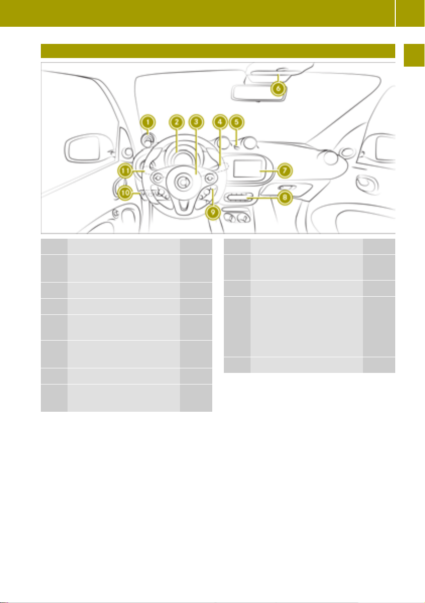
Dashboard
Dashboard
27
>> At a glance.
Function Page
Charge level display 57
:
Power display 57
Instrument cluster 32
;
Horn
=
Windshield wipers combi-
?
nation switch
Automatic locking feature 73
A
Hazard warning lamps 154
Overhead control panel 30
B
smart Audio-System 89
C
smart Media-System 96
71
Function Page
Climate control system
D
control panel
Ignition lock 52
E
Control panel for:
F
Tailgate release
Forward collision warning 45
Acoustic presence indica-
tor
Lights combination switch 69
G
78
55
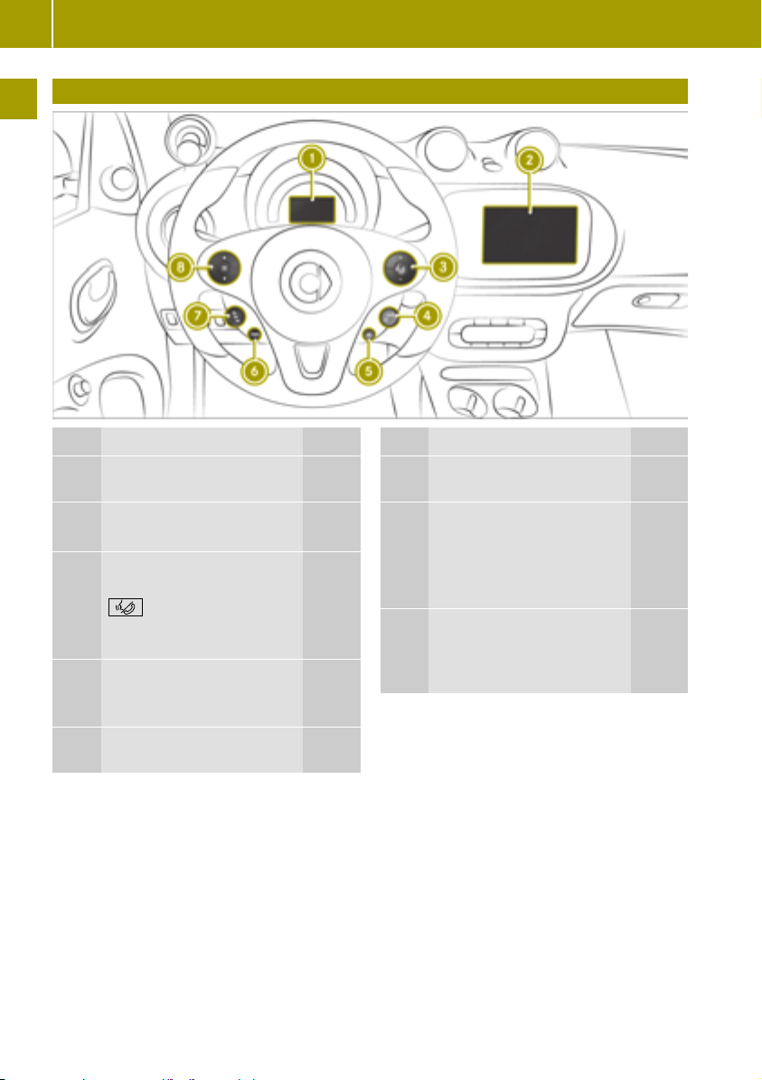
Multifunction steering wheel
28
Multifunction steering wheel
>> At a glance.
Function Page
Color display of the instru-
:
ment cluster
smart Audio-System 89
;
smart Media-System 96
= WX Adjusts the vol-
ume
Switches voice-operated control on or off and
accepts or ends a call
® Increases or stores
?
the current speed
− Decreases current speed 61
° Calls up the last speed
A
stored
85
96
96
61
61
Function Page
± Interrupts cruise
B
control
C ¯ Cruise control button
u Activates cruise control
^ Deactivates cruise
control
D 9: Scrolls through
menus
a Confirms the selec-
tion
61
61
61
85
87

Center console with drawer
Center console with drawer
29
>> At a glance.
Function Page
Cup holder 121
:
Ashtray 81
Drawer 121
;
smart fortwo coupe: coin
=
holder
smart fortwo cabrio: opens
=
and closes the soft top
Selector lever 55
?
Parking brake 53
A
75
Function Page
Cigarette lighter 81
B
Socket 82
smart Media-System: AUX
C
port, USB port and SD card
slot
Cup holder 121
D
Selector lever indicator 54
E
ECO mode 56
F
96

Overhead control panel
30
Overhead control panel
>> At a glance.
Function Page
Left-hand reading lamp 70
:
Interior lighting 70
;
Right-hand reading lamp 70
=
Function Page
PASSENGER AIRBAG indica-
?
tor lamps
Rear-view mirror 50
A
39
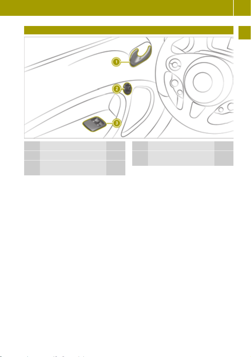
Door control panel
Door control panel
31
>> At a glance.
Function Page
Opens the door 73
:
Adjusts the exterior mir-
;
rors
51
Function Page
Opens and closes the side
=
windows
74

Displays shown in the instrument cluster and the display
32
Displays shown in the instrument cluster and the display
>> At a glance.
Function Page
Speedometer
:
Display
;
Warning and indicator
=
lamps
Doors or tailgate 167
C
Seat belts 168
7
Restraint system 169
6
Drive diagnostics 172
þ
USA: brakes 171
$
Canada: brakes 171
J
USA: ABS 175
ò
Canada: ABS 175
!
÷
h
®
ESP
Tire pressure monitor 177
46
Function Page
Distance warning signal 180
·
Forward collision warning 180
^
12 V battery 181
#
Rear fog lamp 70
R
Front fog lamps 70
O
High-beam headlamps 69
K
Low-beam headlamps 69
L
Parking lamps 70
T
Charging cable 172
è
Cruise control 181
¯
Next service due date
¯
°
READY indicator 181
õ
172

Occupant safety
33
Activating and deactivating the panic
alarm
X
To activate: press the ! button on the
SmartKey for about two seconds.
An alarm sounds and the exterior lighting
flashes.
X
To deactivate: press the ! button on the
SmartKey.
Occupant safety
Restraint system
Protection provided by the restraint system
The restraint system includes the:
R
Seat belt system
R
Air bags
In an accident the restraint system can:
R
reduce the risk of vehicle occupants coming into contact with parts of the vehicle
interior
R
reduce the forces to which vehicle occupants are subjected
A seat belt can only provide maximum protection when worn correctly. Depending on
the type of accident detected, Emergency
Tensioning Devices and/or air bags may supplement a correctly worn seat belt. Not every
accident will trigger the Emergency Tensioning Devices and/or deploy the air bags.
To ensure that the restraint system provides
the maximum protection, every vehicle occupant must:
R
have the seat belt fastened correctly
R
sit in a position that is as upright as possible with the back against the seat backrest
R
have their feet resting on the floor, if possible
R
always be secured in special additional
restraint systems suitable for your vehicle
if under 5 ft (1.50 m) tall
However, no system available today can
completely eliminate injuries and fatalities
in every accident. In particular, the seat belt
and air bag generally do not protect against
objects penetrating the vehicle from the out-
side. The risk of injuries due to a deployed air
bag also cannot be completely eliminated.
Limited protection from restraint system
WARNING
G
Modifications to the restraint system may
cause it to no longer work as intended. The
restraint system may then not perform its
intended protective function and may fail
in an accident or trigger unexpectedly, for
example. This poses an increased risk of
injury or even fatal injury.
Never modify parts of the restraint system.
Never tamper with the wiring, the electronic components or their software.
If the vehicle needs to be adjusted to accommodate a person with disabilities, contact a
qualified specialist workshop. smart recommends that you only use driving assistance
systems which have been approved for your
vehicle by smart.
Contact a smart center for details. USA only:
contact our Customer Assistance Center on
1‑800‑762‑7887 for more details.
Preparing the restraint system for operation
When the ignition is switched on, the 6
restraint system warning lamp lights up
during the system self-test. It goes out no
later than a few seconds after the vehicle is
started. The components of the restraint system are then ready for operation.
Restraint system malfunctions
R
When the ignition is switched on, the 6
restraint system warning lamp does not
light up.
R
While driving, the 6 restraint system
warning lamp remains lit or lights up
repeatedly.
If the restraint system is malfunctioning, the
vehicle's high-voltage electrical system
may also not be deactivated as intended in
the event of an accident.
>> Safety.
Z

Occupant safety
34
DANGER
G
If the restraint system is malfunctioning,
restraint system components may be triggered unintentionally or may not deploy
as intended during an accident. This can
affect for example the Emergency Tensioning Device or the air bag. Furthermore, in
the event of an accident, the vehicle's
high-voltage electrical system may not be
>> Safety.
deactivated as intended. You may be electrocuted if you touch the damaged components of the vehicle's high-voltage electrical system. This poses an increased risk
of injury or even fatal injury.
Have the restraint system checked and
repaired in a qualified specialist workshop
as soon as possible. After an accident,
switch off the ignition immediately and
remove the key from the ignition lock.
Restraint system response during an
accident
The way the restraint system responds
depends on the severity of the impact detected and the apparent type of accident:
R
Head-on collision
R
Rear impact
R
Side impact
R
Rollover
The activation threshold for the restraint
system components is determined based on
the analysis of the sensor values measured at
various points in the vehicle. This process is
pre-emptive in nature. The triggering process of the restraint system components
should take place in good time at the start of
the collision.
Factors which can only be seen and measured after a collision has occurred do not
play a decisive role in the deployment of an
air bag, nor do they provide an indication of
air bag deployment.
The vehicle may be deformed significantly
without an air bag being deployed. This is
the case if only parts which are relatively
easily deformed are affected and the rate of
1
smart fortwo coupe.
2
smart fortwo cabrio.
vehicle deceleration is not high. Conversely,
an air bag may be deployed even though the
vehicle suffers only minor deformation. If,
for instance, very rigid vehicle parts such as
longitudinal body members are hit, the rate
of vehicle deceleration may be sufficient.
The restraint system components can be
activated or triggered independently of each
other:
Component Detected trigger sit-
uation
Emergency Tensioning Device
(ETD) for seat belts
Driver's air bag,
Head-on collision,
rear impact, side
impact, rollover
Head-on collision
front-passenger
front air bag and
knee bag
Side impact air bag Side impact
Windowbag1or
headbag
2
Side impact, roll-
over, head-on colli-
sion
The front-passenger front air bag can only
be deployed in an accident if the PASSENGER
AIR BAG ON indicator lamp is lit. If the frontpassenger seat is occupied, make sure that
the status of the front-passenger front air
bag is correct both before and during the
journey (
G
Y page 39).
WARNING
The air bag parts are hot after an air bag
has been deployed. There is a risk of injury.
Do not touch the air bag parts. Have a
deployed air bag replaced at a qualified
specialist workshop as soon as possible.
smart recommends that you have the
i
vehicle towed to a qualified specialist
workshop after an accident. Take this into
account, particularly if an Emergency
Tensioning Device was triggered or an air
bag was deployed.

Occupant safety
35
If the Emergency Tensioning Devices are
triggered or an air bag is deployed, you will
hear a bang, and a small amount of powder
may also be released:
R
The bang will not usually affect your hearing.
R
In general, the powder released is not hazardous to health but may cause short-term
breathing difficulties to persons suffering
from asthma or other pulmonary conditions.
Provided it is safe to do so, leave the vehicle immediately or open the window in
order to prevent breathing difficulties.
Air bags and pyrotechnic Emergency Tensioning Devices contain perchlorate material, which may require special handling and
environmental protection measures.
National guidelines must be observed during
disposal. In California, see www.dtsc.ca.gov/
HazardousWaste/Perchlorate/index.cfm.
Seat belts
Protection provided by seat belts
Always fasten seat belts correctly before
starting your journey. A seat belt can only
provide maximum protection when worn correctly.
WARNING
G
If the seat belt is not worn correctly, it
cannot perform its intended protective
function. An incorrectly fastened seat belt
can also cause injuries, for example, in the
event of an accident or when braking or
changing direction abruptly. This poses an
increased risk of injury or even fatal
injury.
Always ensure that all vehicle occupants
have their seat belts fastened correctly
and are sitting properly.
R
The seat belt must:
-
not be twisted and must be tight and fit
snugly across your body
-
be routed across the center of the shoulder and as low down across your hips as
possible
R
The shoulder section of the seat belt
should not touch your neck nor be routed
under your arm or behind your back.
R
Avoid wearing bulky clothing, e.g. a winter
coat.
R
Press the lap belt down into your hip joints
and pull tight by the shoulder section of
the belt. The lap belt must never be routed
across your stomach or abdomen.
R
Never route the seat belt across sharp,
pointed, abrasive or fragile objects.
R
Only one person per seat belt. Infants and
children must never travel sitting on the
lap of a vehicle occupant.
R
Never secure objects with a seat belt if the
seat belt is also being used by one of the
vehicle's occupants. Always observe the
notes on "Loading the vehicle" for securing
objects, luggage or loads (
Y page 122).
Also make sure that objects are never
placed between an occupant and the seat,
e.g. a cushion.
The front-passenger seat belt is equipped
with a special seatbelt retractor. Further
information can be found under "Special
seatbelt retractor" (
Y page 43).
If children are traveling in the vehicle, be
sure to observe the instructions and safety
notes on "Children in the vehicle"
Y page 42).
(
Limited protection from seat belts
WARNING
G
The seat belt does not offer the intended
level of protection if you have not moved
the backrest to an almost vertical position.
When braking or in the event of an accident, you could slide underneath the seat
belt and sustain abdomen or neck injuries,
for example. This poses an increased risk of
injury or even fatal injury.
Adjust the seat properly before beginning
your journey. Always ensure that the
>> Safety.
Z

Occupant safety
36
backrest is in an almost vertical position
and that the shoulder section of your seat
belt is routed across the center of your
shoulder.
WARNING
G
Persons less than 5 ft (1.50 m) tall cannot
wear the seat belt correctly without an
additional and suitable restraint system.
>> Safety.
If the seat belt is not worn correctly, it
cannot perform its intended protective
function. An incorrectly fastened seat belt
can also cause injuries, for example, in the
event of an accident or when braking or
changing direction abruptly. This poses an
increased risk of injury or even fatal
injury.
For this reason, always secure persons
under 5 ft (1.50 m) tall in suitable additional restraint systems.
WARNING
G
If objects between the seat and door are
blocking the moving belt anchorage on the
seat, this restricts the restraining effect of
the seat belt. The seat belt can no longer
protect as intended. This poses an
increased risk of injury or even fatal
injury.
Make sure that no objects are between the
seat and door before beginning a journey.
WARNING
G
The seat belts may not perform their intended protective function if:
R
they are damaged, modified, extremely
dirty, bleached or dyed
R
the seat belt buckle is damaged or
extremely dirty
R
the Emergency Tensioning Devices, belt
anchorages or inertia reels have been
modified.
Seat belts may be damaged in an accident,
although the damage may not be visible,
e.g. due to splinters of glass. Modified or
damaged seat belts may tear or fail, e.g. in
an accident. Modified Emergency Tensioning Devices could accidentally trigger or
fail to deploy when necessary. This poses
an increased risk of injury or even fatal
injury.
Never modify the seat belts, Emergency
Tensioning Devices, belt anchorages and
inertia reels. Make sure that the seat belts
are undamaged, not worn out and clean.
Following an accident, have the seat belts
checked immediately at a qualified specialist workshop.
Only use seat belts which have been
approved specifically for your vehicle by
smart.
WARNING
G
Emergency Tensioning Devices that have
deployed pyrotechnically are no longer
operational and are unable to perform
their intended protective function. This
poses an increased risk of injury or even
fatal injury.
Have pyrotechnically triggered Emergency Tensioning Devices replaced immediately at a qualified specialist workshop.
smart recommends that you have the vehicle
towed to a qualified specialist workshop
after an accident.
Make sure that the seat belt is fully rolled
!
up. Otherwise, the seat belt or belt tongue
will be trapped in the door or in the seat
mechanism. This could damage the door,
the door trim panel and the seat belt. Damaged seat belts can no longer fulfill their
protective function and must be replaced.
Visit a qualified specialist workshop.
Fastening and releasing the seat belt
If the seat belt is pulled out quickly or
sharply, the inertia reel locks. The belt strap
cannot be pulled out any further.
If the front-passenger seat is not occu-
!
pied, do not engage the seat belt tongue in
the buckle on the front-passenger seat.
Otherwise, in addition to other systems,
the Emergency Tensioning Device could

Occupant safety
37
also be triggered in the event of an accident and would need to be replaced.
For easy fastening, the seat belt is guided
through the seat belt guide on the side of the
seat.
Buckle
:
Seat belt tongue
;
X
To fasten: always engage seat belt
tongue ; into buckle : of the corresponding seat.
X
To release: press the release button in belt
buckle : and guide the seat belt back by
belt tongue ;.
Belt warning for the driver and frontpassenger
The 7 seat belt warning lamp in the
instrument display is a reminder that all
vehicle occupants must wear their seat belts
correctly.
After each start, the 7 seat belt warning
lamp flashes for six seconds.
In addition, there may be a warning tone.
The belt warning goes out as soon as the
doors are closed and the driver and frontpassenger fasten their seat belts.
The belt warning comes on:
R
if the vehicle exceeds a speed of 12 mph
(20 km/h) once and neither the driver nor
the front passenger have fastened their
seat belt
R
if the driver or front-passenger unfasten
their seat belt while the vehicle is moving
Air bags
Overview of air bags
The installation location of an air bag is
identified by the AIRBAG symbol.
A deployed air bag can increase the level of
protection provided to the vehicle occupant.
Air bag Possible protection
:
Headbag
Driver's knee
;
bag
Driver's air
=
bag
Front-
?
passenger
knee bag
Front-
A
passenger
front air bag
B
Windowbag
Side impact
C
air bag
The front-passenger front air bag can only
be deployed in an accident if the PASSENGER
AIR BAG ON indicator lamp is lit. If the frontpassenger seat is occupied, make sure that
the status of the front-passenger front air
bag is correct both before and during the
journey (
Y page 39).
for:
3
Head
Thigh, knee and lower
leg
Head and thorax
Thigh, knee and lower
leg
Head and thorax
4
Head
Thorax and pelvis
>> Safety.
3
smart fortwo cabrio
4
smart fortwo coupe
Z

Occupant safety
38
Protection provided by the air bags
Depending on the type of accident, an air bag
can supplement a correctly worn seat belt
and provide added protection.
WARNING
G
If you do not sit in the correct seat position,
the air bag cannot protect as intended and
could even cause additional injury when
deployed. This poses an increased risk of
>> Safety.
injury or even fatal injury.
To avoid hazardous situations, always
make sure that all of the vehicle's occupants:
R
have fastened their seat belts correctly,
including pregnant women
R
are sitting correctly and maintain the
greatest possible distance to the air
bags
R
follow the following instructions
Always make sure that there are no objects
between the air bag and the vehicle's occupants.
To avoid risks as a result of a deployed air
bag:
R
Adjust seats correctly before starting your
journey and move the driver's and frontpassenger seat as far back as possible.
Always observe the information on the
correct driver's seat position (
R
Only hold onto the outside of the steering
wheel rim. This allows the air bag to be
fully deployed.
R
Always lean against the backrest while
driving. Do not lean forwards or lean
against the door or side window. You may
otherwise be in the deployment area of the
air bags.
R
Always keep your feet on the floor. Do not
put your feet on the dashboard, for example. Your feet may otherwise be in the
deployment area of the air bag.
R
When children are traveling in the vehicle,
follow the related additional notes
Y page 42).
(
R
Always properly stow and secure objects.
Y page 48).
Objects in the vehicle interior may limit an
air bag's ability to function correctly. Therefore, always make sure that:
R
There are no people, animals or objects
between the vehicle occupants and an airbag.
R
There are no objects between the seat, the
door and the door pillar (B-pillar).
R
No hard objects, e.g. coat hangers, are
hanging on the grab handles or coat hooks.
R
No accessories, such as cup holders, are
attached within the deployment area of an
airbag, e.g. to doors, side
windows or side
trim panels.
R
No heavy, sharp-edged or fragile objects
are kept in the pockets of clothing. Store
such objects in a suitable place.
Limited protection from air bags
WARNING
G
If you modify the air bag cover or affix
objects such as stickers to it, the air bag
can no longer function correctly. There is
an increased risk of injury.
Never modify an air bag cover or affix
objects to it.
WARNING
G
Unsuitable seat covers can obstruct or
even prevent the deployment of the air
bags integrated in the seats. Consequently, the air bags cannot protect vehicle occupants as intended. In addition, the
operation of the automatic frontpassenger front air bag deactivation system could be restricted. This poses an
increased risk of injury or even fatal
injury.
Only use seat covers that have been
approved for the corresponding seats by
smart.
WARNING
G
Sensors to control the air bags are located
in the doors. Modifications or work not performed correctly to the doors or door paneling, as well as damaged doors, can lead to

the function of the sensors being impaired.
The air bags might therefore not function
properly anymore. Consequently, the air
bags cannot protect vehicle occupants as
they are designed to do. There is an
increased risk of injury.
Never modify the doors or parts of the
doors. Always have work on the doors or
door paneling carried out at a qualified
specialist workshop.
WARNING
G
A deployed air bag no longer offers any
protection and cannot provide the intended protection in an accident. There is an
increased risk of injury.
Have the vehicle towed to a qualified specialist workshop in order to have a
deployed air bag replaced.
Have deployed air bags replaced immediately.
Status of the front-passenger front air
bag
Important notes when the front-passenger
seat is occupied
The automatic front-passenger air bag deactivation system can detect if there is a person
or a child restraint system on the frontpassenger seat. The front-passenger air bag
is enabled or disabled accordingly.
When installing a child restraint system on
the front-passenger seat:
R
ensure that the child restraint system is
positioned correctly (
R
always comply with the child restraint
Y page 42)
system manufacturer's installation
instructions
R
never place objects, such as cushions,
under or behind the child restraint system
R
the base of the child restraint system must
lie fully against the seat cushion of the
front-passenger seat
Occupant safety
R
the back of a forward-facing child
restraint system must lie as flat as possible against the front-passenger backrest
R
the child restraint system must not touch
the roof. Adjust the angle of the seat backrest accordingly
WARNING
G
Objects between the seat surface and the
child restraint system could affect the
function of the automatic front-passenger
front air bag deactivation system. This
could result in the front-passenger air bag
not functioning as intended during an
accident. This poses an increased risk of
injury or even fatal injury.
Do not place any objects between the seat
surface and the child restraint system. The
entire base of the child restraint system
must always rest on the seat cushion of the
front-passenger seat. The backrest of the
forwardfacing child restraint system
must, as far as possible, be resting on the
backrest of the front-passenger seat.
Always comply with the child restraint
system manufacturer's installation
instructions.
A person on the front-passenger seat must:
R
have the seat belt fastened correctly
R
sit in a position that is as upright as possible with the back against the seat backrest
R
have their feet resting on the floor, if possible
Otherwise the front-passenger air bag can
be disabled by mistake, for instance because
the front-passenger:
R
has transferred their weight by leaning on
the armrests in the vehicle
R
sits in such a way that the weight on the
seat cushion is reduced
WARNING
G
If the PASSENGER AIR BAG OFF indicator
lamp is lit, the front-passenger front air
bag is disabled. It will not be deployed in
the event of an accident and cannot perform its intended protective function. A
39
>> Safety.
Z
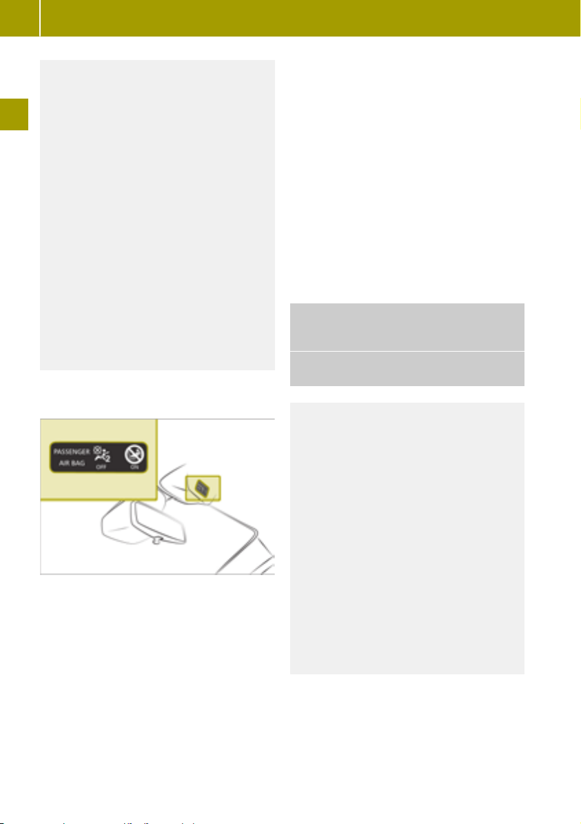
Occupant safety
40
person in the front-passenger seat could
then, for example, come into contact with
the vehicle's interior, especially if the person is sitting too close to the dashboard.
This poses an increased risk of injury or
even fatal injury.
When the front-passenger seat is occupied, always ensure that:
R
the classification of the person in the
>> Safety.
front-passenger seat is correct and the
front-passenger front air bag is enabled
or disabled in accordance with the person in the front-passenger seat
R
the front-passenger seat has been
moved back as far back as possible.
R
the person is seated correctly.
Make sure, both before and during the
journey, that the status of the frontpassenger front air bag is correct.
PASSENGER AIR BAG indicator lamps
System self-test
When the ignition is switched on, both
PASSENGER AIR BAG ON and OFF indicator
lamps light up at the same time during the
system self-test.
The indicator lamps then display the status
of the front-passenger front air bag:
R
PASSENGER AIR BAG ON lights up: the
front-passenger front air bag is enabled.
If, in the case of an accident, all deployment criteria are met, the front-passenger
front air bag is deployed.
R
PASSENGER AIR BAG OFF lights up: the
front-passenger front air bag is disabled.
It will then not be deployed in the event of
an accident.
If the PASSENGER AIR BAG OFF indicator lamp
and restraint system warning lamp 6
light up at the same time, the frontpassenger seat may not be used. In this case,
do not install a child restraint system on the
front-passenger seat. Have the automatic
front-passenger air bag deactivation system
checked and repaired immediately at a
qualified specialist workshop.
Status indicator
If the front-passenger seat is occupied, make
sure that the status of the front-passenger
front air bag is correct for the prevailing
conditions both before and during the journey.
After installing a rearward-facing child
restraint system on the front-passenger
seat:
PASSENGER AIR BAG OFF must be lit continuously.
WARNING
G
If you secure a child in a rearward-facing
child restraint system on the frontpassenger seat and the PASSENGER AIR
BAG ON indicator lamp is lit up, the frontpassenger front air bag may deploy in an
accident. The child could be struck by the
air bag. This poses an increased risk of
injury or even fatal injury.
Make sure that the front-passenger front
air bag has been deactivated. The
PASSENGER AIR BAG OFF indicator lamp
must be lit.
NEVER use a rearward-facing child
restraint on a seat protected by an ACTIVE
FRONT AIR BAG in front of it; DEATH or
SERIOUS INJURY to the child can occur.
Observe the vehicle-specific notes when
installing a child restraint system on the
front-passenger seat (
Y page 42).
The PASSENGER AIR BAG ON indicator lamp
may light up, depending on the child
restraint system and the size of the child. In
this case, do not install the rearward-facing

Occupant safety
41
child restraint system on the frontpassenger seat.
After installing a forward-facing child
restraint system on the front-passenger
seat:
PASSENGER AIR BAG OFF or PASSENGER AIR
BAG ON may be lit continuously, depending
on the child restraint system and the
child's stature. Always observe the following notes:
WARNING
G
If you secure a child in a forward-facing
child restraint system on the frontpassenger seat and you position the frontpassenger seat too close to the dashboard,
in the event of an accident, the child could:
R
come into contact with the vehicle's
interior if the PASSENGER AIR BAG OFF
indicator lamp is lit, for example
R
be struck by the air bag if the
PASSENGER AIR BAG ON is lit up
This poses an increased risk of injury or
even fatal injury.
Move the front-passenger seat as far back
as possible. Always make sure that the
shoulder belt strap is correctly routed from
the vehicle belt guide to the shoulder belt
guide on the child restraint system. The
shoulder belt strap must be routed forwards and downwards from the belt guide.
Always observe the child restraint system
manufacturer's installation instructions.
Observe the vehicle-specific notes when
installing a child restraint system on the
front-passenger seat (
Y page 42).
If a person is sitting on the frontpassenger seat:
PASSENGER AIR BAG OFF or PASSENGER AIR
BAG ON may be lit continuously, depending
on the person's stature. Always observe
the following notes:
If the front-passenger seat is occupied by:
R
an adult or a person of corresponding stature, the PASSENGER AIR BAG ON indicator
lamp must be lit continuously. This indicates that the front-passenger air bag is
enabled
If the PASSENGER AIR BAG OFF lights up
continuously, the front-passenger seat
must not be used by an adult or person of
corresponding stature.
R
a person of smaller stature (e.g. a teenager
or small adult), either the PASSENGER AIR
BAG OFF or PASSENGER AIR BAG ON lamp
lights up continuously, depending on the
Occupant Classification System result
-
PASSENGER AIRBAG ON is lit continuously: move the front-passenger seat as
far back as possible
-
PASSENGER AIRBAG OFF is lit continuously: the front-passenger seat must
not be used by a person of small stature
WARNING
G
If the PASSENGER AIRBAG OFF indicator
lamp remains lit after the system self-test,
the front-passenger front air bag is disabled. It will not be deployed in the event of
an accident. In this case, the frontpassenger front air bag cannot perform its
intended protective function, e.g. when a
person is seated in the front-passenger
seat.
That person could, for example, come into
contact with parts of the vehicle's interior,
especially if the person is sitting too close
to the dashboard. This poses an increased
risk of injury or even fatal injury.
When the front-passenger seat is occupied, always ensure that:
R
the classification of the person in the
front-passenger seat is correct and the
front-passenger front air bag is enabled
or disabled in accordance with the person in the front-passenger seat
R
the person is seated properly with a correctly fastened seat belt
R
the front-passenger seat has been
moved as far back as possible
>> Safety.
Z

Children in the vehicle
42
If children are traveling in the vehicle, be
sure to observe the notes on "Children in the
vehicle" (
Y page 42).
Children in the vehicle
Traveling safely with children on board
WARNING
G
If you leave children unsupervised in the
>> Safety.
vehicle, they could set it in motion by, for
example:
R
release the parking brake.
R
shift the automatic transmission out of
the parking position P.
R
start the engine.
In addition, they may operate vehicle
equipment and become trapped. There is a
risk of an accident and injury.
When leaving the vehicle, always take the
SmartKey with you and lock the vehicle.
Never leave children unsupervised in the
vehicle.
WARNING
G
If persons, particularly children are subjected to prolonged exposure to extreme
heat or cold, there is a risk of injury, possibly even fatal. Never leave children
unattended in the vehicle.
WARNING
G
If the child restraint system is subjected to
direct sunlight, parts may get very hot.
Children may burn themselves on these
parts, particularly on the metal parts of the
child restraint system. There is a risk of
injury.
If you leave the vehicle, taking the child
with you, always ensure that the child
restraint system is not exposed to direct
sunlight. Protect it with a blanket, for
example. If the child restraint system has
been exposed to direct sunlight, let it cool
down before securing the child in it. Never
leave children unattended in the vehicle.
The use of seat belts and child restraint systems is required by law in:
R
all 50 states
R
the U.S. territories
R
the District of Columbia
R
all Canadian provinces
All child restraint systems must meet the
following standards:
R
U.S. Federal Motor Vehicle Safety Standards 213 and 225
R
Canadian Motor Vehicle Safety Standards
213 and 210.2
You can obtain further information about the
correct child restraint system from any
smart center.
To provide better protection to children
younger than twelve years old and under 5 ft
(1.50 m) tall, smart recommends always
observing the following:
R
Secure children only in a child restraint
system that is appropriate for the age,
weight and size of the child and that is
recommended and suitable for use in smart
vehicles. Make sure you observe the
instructions for correct use of the child
restraint system.
R
Only use the following securing systems
with the child restraint systems:
-
the seat belt system
-
the Top Tether anchorages
R
The manufacturer's child restraint system
installation instructions.
R
The warning labels in the vehicle interior
and on the child restraint system.
WARNING
G
If the child restraint system is installed
incorrectly on a suitable seat, it cannot
protect as intended. The child cannot then
be restrained in the event of an accident,
heavy braking or sudden changes of direction. There is an increased risk of injury,
possibly even fatal.
Make sure that you observe the child
restraint system manufacturer's installation instructions and the notes on use.
Please ensure, that the base of the child
restraint system is always resting completely on the seat cushion. Never place

Children in the vehicle
43
objects, e.g. cushions, under or behind the
child restraint system. Only use child
restraint systems with the original cover
designed for them. Only replace damaged
covers with genuine covers.
WARNING
G
If the child restraint system is installed
incorrectly or is not secured, it can come
loose in the event of an accident, heavy
braking or a sudden change in direction.
The child restraint system could be thrown
about, striking vehicle occupants. There is
an increased risk of injury, possibly even
fatal.
Always install child restraint systems
properly, even if they are not being used.
Make sure that you observe the child
restraint system manufacturer's installation instructions.
WARNING
G
Child restraint systems or their securing
systems which have been damaged or subjected to a load in an accident can no longer
protect as intended. The child cannot then
be restrained in the event of an accident,
heavy braking or sudden changes of direction. There is an increased risk of injury,
possibly even fatal.
Replace child restraint systems which
have been damaged or subjected to a load
in an accident as soon as possible. Have the
securing systems on the child restraint
system checked at a qualified specialist
workshop, before you install a child
restraint system again.
A booster seat may be necessary to achieve
proper seat belt positioning for children over
41 lbs (18 kg) or until they reach a height
where a three-point seat belt can be properly
fastened without a booster seat.
Also, always observe the detailed information below:
R
When installing a child restraint system
on the front-passenger seat, observe the
notes on child restraint systems on the
front-passenger seat (
R
Notes on seat belts (Y page 35).
Y page 44).
Activating/deactivating the special
seatbelt retractor of the seat belt
WARNING
G
If the seat belt is released while driving,
the child restraint system will no longer be
secured properly. The special seat belt
retractor is disabled and the inertia real
draws in a portion of the seat belt. The seat
belt cannot be immediately refastened.
There is an increased risk of injury, possibly even fatal.
Stop the vehicle immediately, paying
attention to road and traffic conditions.
Reactivate the special seat belt retractor
and secure the child restraint system
properly.
When activated, the special seat belt retractor ensures that the seat belt on the frontpassenger seat does not slacken once the
child restraint system is secured.
Always comply with the child restraint system manufacturer's installation instructions
when installing and removing the child
restraint system.
Activating the special seat belt retractor:
X
Pull the seat belt out fully and let the seat
belt retractor retract it again.
When the special seat belt retractor is
activated, you should hear a ratcheting
sound.
X
Push the child seat restraint system down
until the seat belt is tight.
Deactivating the special seat belt retractor:
X
Press the release button on the seat belt
buckle.
X
Hold the belt tongue firmly and guide it
back towards the belt loop.
Securing Top Tether
Top Tether can reduce the risk of injury,
since it provides an additional connection
Z
>> Safety.

Children in the vehicle
44
between the child restraint system and the
vehicle.
The child restraint system must be equipped
with a Top Tether belt.
>> Safety.
Top Tether anchorage ; is mounted to the
cargo compartment floor.
X
Route Top Tether belt ? back over the
head restraint, keeping it as central as
possible, into the cargo compartment
through loop :.
X
Hook Top Tether hook = of Top Tether
belt ? into Top Tether anchorage ;.
Lift up the carpet a little if necessary.
Make sure that:
R
Top Tether hook = is hooked into Top
Tether anchorage ; as shown.
R
Top Tether belt ? is not twisted.
X
Tension Top Tether belt ?. Always comply
with the child restraint system manufacturer's installation instructions when
doing so.
Child restraint systems on the frontpassenger seat
Notes on child restraint systems
If you secure a child in a child restraint system on the front-passenger seat, always
observe the information and safety notes on
the automatic front-passenger front air bag
deactivation system (
Y page 39).
You avoid risks resulting from:
R
a child restraint system that is not detected by the automatic front-passenger
front air bag deactivation system
R
the unintentional deactivation of the
front-passenger front air bag
R
positioning the child restraint system
incorrectly
Notes on rearward and forward facing
child restraint systems
If you secure a child in a rearward-facing
child restraint system on the frontpassenger seat, always make sure that the
front-passenger front air bag is deactivated.
This is only the case if the PASSENGER AIR
BAG OFF indicator lamp is permanently lit
Y page 39).
(
When using child restraint systems on the
front-passenger seat, always observe the
following:
R
Move the front-passenger seat as far back
as possible.
R
The base of the child restraint system must
lie fully against the seat cushion of the
front-passenger seat.
R
The back of a forward-facing child
restraint system must lie as flat as possible against the front-passenger backrest.
The child restraint system must not touch
the roof or be put under strain by the head
restraint.
R
Adjust the angle of the seat backrest
accordingly.
R
Always make sure that the shoulder belt
strap is correctly routed from the vehicle
belt outlet to the shoulder belt guide on the
child restraint system. The shoulder belt

Driving safely
45
strap must be routed forward and rearward
from the vehicle belt outlet.
R
Never place objects, such as a cushion,
under or behind the child restraint system.
Always comply with the manufacturer's
installation and operating instructions for
the child restraint system used.
Pets in the vehicle
WARNING
G
If you leave animals unattended or unsecured in the vehicle, they could press buttons or switches, for example.
As a result, they could:
R
activate vehicle equipment and become
trapped, for example
R
activate or deactivate systems, thereby
endangering other road users
Unsecured animals could also be flung
around the vehicle in the event of an accident or sudden steering or braking,
thereby injuring vehicle occupants. There
is a risk of an accident and injury.
Never leave animals unattended in the
vehicle. Always secure animals properly
during the journey, e.g. use a suitable animal transport box.
Driving safely
Driving safety system limitations
Make sure you have suitable tires, so that
!
assistance systems and driving safety
systems can work as effectively as possible.
If you fail to adapt your driving style or
become distracted, the driving safety systems can neither reduce the risk of accident
nor override the laws of physics. Driving
safety systems are merely aids designed to
assist driving. You are responsible for the
distance to the vehicle in front, for vehicle
speed and for braking in good time. Always
adapt your driving style to suit the prevailing road, weather and traffic conditions and
maintain a safe distance from the vehicle in
front. Drive carefully.
For safety reasons, smart recommends that
you only use snow chains that have been
specially approved for your vehicle by smart.
Further information can be obtained at a
smart center or a qualified specialist workshop.
Braking with ABS (Anti-lock Braking
System)
ABS regulates brake pressure in such a way
that the wheels do not lock when you brake.
This allows you to continue steering the
vehicle when braking.
The ! (Canada only) or ò (USA only)
abs warning lamp in the instrument cluster
lights up when the ignition is switched on. It
goes out when the engine is running.
ABS works from a speed of about 4 mph
(6 km/h), regardless of road-surface conditions. ABS intervenes in the case of slippery
road surfaces, even when you only brake
gently.
X
To brake while ABS intervenes: continue to
depress the brake pedal with force until
the braking situation is over.
X
To make a full brake application: depress
the brake pedal with full force.
WARNING
G
If ABS is faulty, the wheels could lock when
braking. The steerability and braking
characteristics may be severely impaired.
Additionally, further driving safety systems are deactivated. There is an increased
danger of skidding and accidents.
Drive on carefully. Have ABS checked
immediately at a qualified specialist
workshop.
Using the forward collision warning
Useful information
If a risk of collision with the vehicle in front
is detected, the forward collision warning
alerts the driver both visually and acoustically.
>> Safety.
Z

Driving safely
46
With the help of the radar sensor system, the
forward collision warning can detect obstacles that are in the path of your vehicle for an
extended period of time.
Up to a speed of approximately 45 mph
(70 km/h), the forward collision warning can
react to stationary obstacles, such as stationary or parked vehicles.
Please note
>> Safety.
Observe the notes in the "Limitations of
i
the driving safety systems" (
section.
WARNING
G
The distance warning function does not
react:
R
to people or animals
R
to oncoming vehicles
R
to crossing traffic
R
when cornering
The distance warning function may not
give warnings in all critical situations.
There is a risk of an accident.
Always pay careful attention to the traffic
situation and be ready to brake.
Always adapt your speed to suit the prevailing road and traffic conditions.
Y page 45)
In this case, an intermittent warning tone
also sounds
Detection can be restricted under the following conditions:
R
the vehicle is new or service work has been
carried out on the system. In this case,
observe the information on breaking-in
the vehicle
R
the sensors are dirty or covered
R
in heavy rain or snow
R
there is interference from other radar
sources, e.g. in parking garages
R
the vehicle traveling in front is narrow,
e.g. a motorcycle
R
the vehicle traveling in front is traveling
on a different line
Following any damage to the front end of the
vehicle, have the configuration and operation of the radar sensor checked at a qualified specialist workshop. This also applies to
collisions at slow speeds where there is no
visible damage to the front of the vehicle.
Activating/deactivating the forward collision warning
WARNING
G
The distance warning function cannot
always clearly identify objects and complex traffic situations.
In such cases, the distance warning function may:
R
give an unnecessary warning
R
not give a warning
There is a risk of an accident.
Always pay careful attention to the traffic
situation and do not rely solely on the distance warning function.
The · warning lamp in the instrument
cluster lights up if:
R
the vehicle is rapidly approaching a vehicle traveling in front or a stationary object.
When the ignition is restarted, the forward
collision warning is automatically activated.
X
Press the switch.
If the forward collision warning is deacti-
vated, the LED on the
switch lights up.
On-board computer with color display: the
display shows a message.
Driving with ESP
®
If ESP®detects that the vehicle is deviating
from the direction desired by the driver, one

Driving safely
47
or more wheels are braked to stabilize the
vehicle.
®
supports the driver when pulling away
ESP
on wet or slippery roads. ESP
bilize the vehicle during braking. ESP
®
can also sta-
®
comprises ETS (Electronic Traction System) and
Crosswind Assist.
ETS brakes the drive wheels individually if
they spin. This enables you to pull away and
accelerate on slippery surfaces, for example,
if the road surface is slippery on one side.
Strong crosswind gusts can impair the roadholding of your vehicle when driving
straight ahead.
Crosswind Assist reduces these impairments.
Crosswind Assist is active at vehicle speeds
above 45 mph (70 km/h) when driving
straight ahead or cornering gently.
®
intervenes, pull away carefully and
If ESP
adapt your driving style to the prevailing
road and weather conditions.
If the ÷ warning lamp goes out before
beginning the journey, ESP
®
is active. If ESP
intervenes, the ÷ warning lamp flashes in
the instrument cluster.
WARNING
G
®
If ESP
is malfunctioning, ESP®is unable to
stabilize the vehicle. Additionally, further
driving safety systems are deactivated.
This increases the risk of skidding and an
accident.
Drive on carefully. Have ESP
®
checked at a
qualified specialist workshop.
istics. Have the brake system checked at a
qualified specialist workshop.
>> Safety.
®
Information on EBD (electronic brake
force distribution)
EBD monitors and controls the brake pressure on the rear wheels to improve driving
stability while braking.
WARNING
G
If EBD is malfunctioning, the rear wheels
can lock, e.g. under full braking. This
increases the risk of skidding and an accident.
You should therefore adapt your driving
style to the different handling character-
Z

Correct driver's seat position
48
Understanding functions of the SmartKey
:
% Unlocks the vehicle
;
& Locks the vehicle
é smart fortwo coupé: Opens the
=
upper tailgate (press and hold)
é smart fortwo cabrio: Opens the soft
=
top (press and hold)
?
! Switches the panic alarm on and off
>> Entering and setting up.
(press and hold)
X
To unlockcentrally: press the % button.
The turn signals flash once.
After unlocking, open the vehicle within
i
approximately 2 minutes to prevent it from
locking itself again and arming the antitheft alarm system.
X
To unlock and open the upper tailgate
(smart fortwo coupé): press and hold the
é button.
X
To open the soft top to the B-pillar (smart
fortwo cabrio): press and hold the é
button.
X
To lock centrally: press the & button.
The turn signals flash twice.
X
To switch the panic alarm on and off: press
the ! button for approximately two
seconds.
An alarm sounds and the exterior lighting
flashes.
Opening the door
X
Press the # button on the SmartKey.
X
Open the door.
After unlocking, open the vehicle within
i
approximately 2 minutes to prevent it from
locking itself again and arming the antitheft alarm system.
Correct driver's seat position
WARNING
G
You could lose control of your vehicle if you
do the following while driving:
R
adjust the driver's seat, steering wheel
or mirrors
R
fasten the seat belt
There is a risk of an accident.
Adjust the driver's seat, steering wheel or
mirrors and fasten your seat belt before
starting the engine.
Observe the following rules on the correct
driver's seat position:
R
the driver must be as far away from the
driver's air bag as possible (
R
the driver must be wearing seat belt =
properly.
R
the driver must be able to depress the pedals properly.
R
the driver must be able to move their legs
freely.
R
the driver must be able to reach steering
wheel : with their arms slightly bent.
R
the driver must be able to see all the displays in the instrument cluster clearly.
R
move seat backrest ; to an almost vertical
position.
R
you are sitting in a normal upright position.
R
the seat belt must fit snugly across your
body.
Y page 37).

R
the seat belt must be routed across the
middle of your shoulder.
R
the seat belt must be routed in your pelvic
area across the hip joints.
R
adjust the rear-view and exterior mirror so
that the driver has a good view of the road
and traffic conditions.
Adjusting the seats
Please note
WARNING
G
Children could become trapped if they
adjust the seats, particularly when unattended. There is a risk of injury.
When leaving the vehicle, always take the
SmartKey with you and lock the vehicle.
Never leave children unsupervised in the
vehicle.
WARNING
G
If the driver's seat is not engaged, it could
move unexpectedly while the vehicle is in
motion. This could cause you to lose control of the vehicle. There is a risk of an
accident.
Always make sure that the driver's seat is
engaged before starting the vehicle.
WARNING
G
When you adjust a seat, you or other vehicle occupants could become trapped, e.g.
on the seat guide rail. There is a risk of
injury.
Make sure when adjusting a seat that no
one has any body parts in the sweep of the
seat.
Adjusting the seats
for example. This poses an increased risk of
injury or even fatal injury.
Adjust the seat properly before beginning
your journey. Always ensure that the
backrest is in an almost vertical position
and that the shoulder section of your seat
belt is routed across the center of your
shoulder.
WARNING
G
If the steering wheel is unlocked while the
vehicle is in motion, it could change position unexpectedly. This could cause you to
lose control of the vehicle. There is a risk of
an accident.
Before starting off, make sure the steering
wheel is locked. Never unlock the steering
wheel while the vehicle is in motion.
WARNING
G
You could lose control of your vehicle if you
do the following while driving:
R
adjust the driver's seat, steering wheel
or mirrors
R
fasten the seat belt
There is a risk of an accident.
Adjust the driver's seat, steering wheel or
mirrors and fasten your seat belt before
starting the engine.
Make sure that there are no objects in the
!
footwell under or behind the seats when
moving the seats back. There is a risk that
the seats and/or the objects could be damaged.
Observe the safety notes on "Air bags"
Y page 38) and "Children in the vehicle"
(
Y page 42).
(
49
>> Entering and setting up.
WARNING
G
The seat belt does not offer the intended
level of protection if you have not moved
the backrest to an almost vertical position.
When braking or in the event of an accident, you could slide underneath the seat
belt and sustain abdomen or neck injuries,
Z

Adjusting the mirrors
50
Adjusting the seat fore-and-aft position
Seat with a lever
>> Entering and setting up.
Seat with a handwheel
To adjust the seat fore-and-aft position, the
seat belt must not be fastened.
X
Lift lever =.
X
Slide the seat forward or back.
The seat engages audibly.
Adjusting the seat backrest (seat with a
handwheel)
X
Turn handwheel ? forward or back.
Adjusting the mirrors
Adjusting the rear-view mirror
X
Move the rear-view mirror up, down, left or
right.
Manually setting the rear-view mirror
to anti-glare mode
X
Fold lever : forward.
Understanding the automatic antiglare rear-view mirror
Please note
Adjusting the seat height (seat with a
lever only)
X
Pull handle ; up or push it down several
times.
Adjusting the seat backrest (seat with a
lever)
X
Pull lever : forward.
X
At the same time, move the backrest
forward or back.
WARNING
G
Electrolyte may escape if the glass in an
automatic anti-glare mirror breaks. The
electrolyte is harmful and causes irritation. It must not come into contact with
your skin, eyes, respiratory organs or
clothing or be swallowed. There is a risk of
injury.
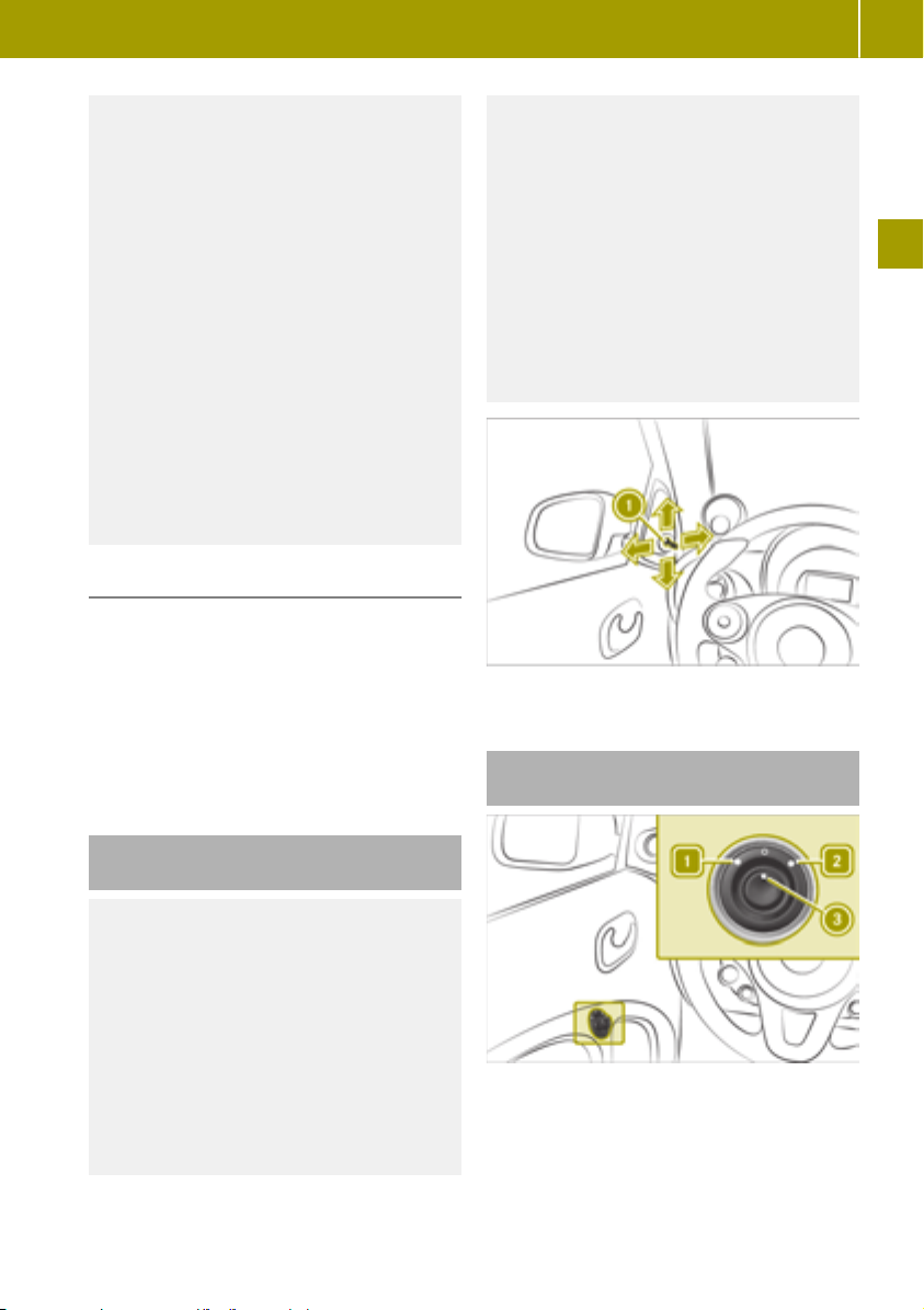
Adjusting the mirrors
51
If you come into contact with the electrolyte, observe the following:
R
Rinse off the electrolyte from your skin
immediately with water.
R
Immediately rinse the electrolyte out of
your eyes thoroughly with clean water.
R
If the electrolyte is swallowed, immediately rinse your mouth out thoroughly.
Do not induce vomiting.
R
If electrolyte comes into contact with
your skin or hair or is swallowed, seek
medical attention immediately.
R
Immediately change out of clothing
which has come into contact with electrolyte.
R
If an allergic reaction occurs, seek medical attention immediately.
Useful information
The rear-view mirror automatically goes into
anti-glare mode if simultaneously:
R
the ignition is switched on
R
incident light from headlamps hits the
sensor in the interior mirror
The rear-view mirror does not go into antiglare mode if reverse gear is engaged or if the
interior lighting is switched on.
WARNING
G
The exterior mirror on the front-passenger
side reduces the size of the image. Visible
objects are actually closer than they
appear. This means that you could misjudge the distance from road users traveling behind, e.g. when changing lane. There
is a risk of an accident.
For this reason, always make sure of the
actual distance from the road users traveling behind by glancing over your shoulder.
X
Move lever : up, down, left or right.
Adjusting the exterior mirrors electrically
>> Entering and setting up.
Adjusting the exterior mirrors manually
WARNING
G
You could lose control of your vehicle if you
do the following while driving:
R
adjust the driver's seat, steering wheel
or mirrors
R
fasten the seat belt
There is a risk of an accident.
Adjust the driver's seat, steering wheel or
mirrors and fasten your seat belt before
starting the engine.
In order to adjust the exterior mirrors electrically, the ignition must be switched on.
X
To select the left or right exterior mirror:
turn control = left 1 or right 2.
X
To adjust the exterior mirrors: move control = up, down, left or right.
Z

Pulling away
52
Starting the engine
Please note
WARNING
G
If children are left unsupervised in the
vehicle, they could:
R
open the doors, thus endangering other
people or road users.
R
get out and disrupt traffic.
R
operate the vehicle's equipment.
Additionally, children could set the vehicle in motion if, for example, they:
R
release the parking brake.
>> Driving.
R
shifting the automatic transmission out
of park position P
R
Start the engine.
There is a risk of an accident and injury.
When leaving the vehicle, always take the
SmartKey with you and lock the vehicle.
Never leave children or animals unattended in the vehicle. Always keep the SmartKey out of reach of children.
WARNING
G
If you attach heavy or large objects to the
SmartKey, the SmartKey could be unintentionally turned in the ignition lock. This
could cause the engine to be switched off.
There is a risk of an accident.
Do not attach any heavy or large objects to
the SmartKey. Remove any bulky key rings
before inserting the SmartKey into the
ignition lock.
To insert the SmartKey into the ignition
u
lock
To switch on the power supply
1
To switch on the ignition
2
To start the engine
3
Automatic transmission
X
Turn the SmartKey to position 3.
The READY
indicator appears in the instru-
ment cluster. A tone sounds.
X
Shift out of transmission position j or i.
Pulling away
Please note
WARNING
G
Objects in the driver's footwell may
restrict the clearance around the pedals or
block a depressed pedal. This jeopardizes
the operating and road safety of the vehicle. There is a risk of an accident.
Stow all objects securely in the vehicle so
that they do not get into the driver's footwell. When using floormats or carpets,
make sure that they are properly secured
so that they do not slip or obstruct the
pedals. Do not place several floormats or
carpets on top of one another.

Pulling away
53
WARNING
G
Unsuitable footwear can hinder correct
usage of the pedals, e.g.:
R
shoes with thick soles
R
shoes with high heels
R
slippers
There is a risk of an accident.
Wear suitable footwear to ensure correct
usage of the pedals.
WARNING
G
If you switch off the ignition while driving,
safety-relevant functions are only available with limitations, or not at all. This
could affect, for example, the power steering and the brake boosting effect. You will
require considerably more effort to steer
and brake. There is a risk of an accident.
Do not switch off the ignition while driving.
WARNING
G
If you operate mobile communication
equipment when driving, you may be distracted from the traffic situation. You
could also lose control of the vehicle. There
is a risk of an accident.
Only operate this equipment when the
vehicle is stationary.
Observe the legal requirements for the country in which you are driving. Some jurisdictions prohibit the driver from using a mobile
phone while driving a vehicle.
If you make a call while driving, always use
hands-free mode. Only use the telephone
when the traffic situation permits. If you are
unsure, pull over to a safe location and stop
before using the telephone.
Bear in mind that at a speed of only 30 mph
(approximately 50 km/h), the vehicle covers a
distance of 44 ft (approximately 14 m) per
second.
Note the following when pulling away:
R
Do not drive with the parking brake
applied.
R
Use caution when pulling away on slippery
surfaces.
R
Do not allow tires to spin.
R
Depress the brake pedal and keep it
depressed.
R
Press the release button on the selector
lever.
R
Shift the gear selector lever to position h
or k.
Drinking and driving
WARNING
G
Drinking and driving and/or taking drugs
and driving are very dangerous combinations. Even a small amount of alcohol or
drugs can affect your reflexes, perceptions
and judgment.
The possibility of a serious or even fatal
accident is greatly increased when you
drink or take drugs and drive.
Do not drink or take drugs and drive or
allow anyone to drive who has been drinking or taking drugs.
Using the parking brake
Please note
WARNING
G
If the parking brake has not been fully
released when driving, the parking brake
can:
R
overheat and cause a fire
R
lose its hold function.
There is a risk of fire and an accident.
Release the parking brake fully before
driving off.
>> Driving.
WARNING
G
If you must brake the vehicle with the
parking brake, the braking distance is
Z

Automatic transmission
54
considerably longer and the wheels could
lock. There is an increased danger of skidding and accidents.
Only use the parking brake to brake the
vehicle when the service brake is faulty. Do
not apply the parking brake too firmly. If
the wheels lock, release the parking brake
until the wheels begin turning again.
WARNING
G
If you leave children unsupervised in the
vehicle, they could set it in motion by, for
example:
R
release the parking brake.
>> Driving.
R
shift the automatic transmission out of
the parking position P.
R
start the engine.
In addition, they may operate vehicle
equipment and become trapped. There is a
risk of an accident and injury.
When leaving the vehicle, always take the
SmartKey with you and lock the vehicle.
Never leave children unsupervised in the
vehicle.
Applying the parking brake
Release Parking Brake
X
Depress the brake pedal and keep it
depressed.
X
Press release button : on parking
brake ; and move the parking brake down
to the stop.
Hill start assist
WARNING
G
After a short time, hill start assist will no
longer brake your vehicle and it could roll
away. There is a risk of an accident and
injury.
Therefore, quickly move your foot from the
brake pedal to the accelerator pedal. Never
leave the vehicle when it is held by hill
start assist.
Hill start assist keeps the vehicle in place
when driving uphill as soon as the brake
pedal is released.
Hill start assist is only active in the following situations:
R
when pulling away on an uphill slope
R
when the parking brake is released
R
the transmission is not in position i
R
ESP®is functioning correctly
X
Release the brake pedal.
The vehicle is then held for about one second.
X
Pull away.
X
Pull parking brake ; up.
The brake lights do not light up when you
brake the vehicle with the parking brake.
Automatic transmission
Please note
WARNING
G
The automatic transmission switches to
neutral position N when you switch off the
engine. The vehicle may roll away. There is
a risk of an accident.
Before switching off the engine, always
switch to parking position P. Prevent the
parked vehicle from rolling away by
applying the parking brake.

Acoustic presence indicator
55
Transmission position display
Only engage park position B when the
!
vehicle is stationary. Otherwise, you could
damage the transmission.
Only shift into reverse gear C when
!
the vehicle is stationary. Otherwise, you
could damage the transmission.
Only shift into neutral A when the
!
vehicle is stationary. Otherwise, you could
damage the transmission.
The following transmission positions are
available:
R
B Park position
Position P should not be used to brake the
vehicle when parking. To secure the vehicle, apply the parking brake in addition to
shifting to transmission position P.
R
C Reverse gear
R
A Neutral
No power is transmitted from the engine to
the drive wheels.
R
7 Drive
Changing the transmission position
Maximum acceleration (kickdown)
To reach maximum acceleration, use kickdown:
X
Depress the accelerator pedal beyond the
pressure point.
X
Ease off the accelerator pedal once the
desired speed is reached.
Using the turn signals
The ignition must be switched on in order to
use the turn signals.
X
To indicate: press the combination switch
in the direction of arrow 1 (right) or 2
(left) past the point of resistance.
X
To indicate briefly: press the combination
switch briefly to the point of resistance.
The turn signal flashes three times.
>> Driving.
Park position with parking lock
B
Reverse gear
C
Neutral
A
Drive
7
The ignition must be switched on in order to
shift the transmission to positions j, i or
k. To shift the transmission from position P,
you must also depress the brake pedal.
X
Press release knob :.
X
Shift the selector lever to the desired
transmission position.
Acoustic presence indicator
Useful information
Vehicles with an electric motor generate
much less driving noise than vehicles with
internal combustion engines. As a result,
your vehicle may not be heard by other road
users in certain situations.
In order to allow your vehicle to be heard
when it is moving at slow speeds, a sound
generator installed in the vehicle produces a
specific noise at speeds between 0 and
18 mph (30 km/h). This function is called the
acoustic presence indicator. It makes it possible for other road users, especially pedestrians and cyclists, to hear the vehicle bet-
Z

Driving economically
56
ter. The acoustic presence indicator can also
be heard in the vehicle interior.
The volume of the acoustic presence indicator depends on the engine speed. The greater
the acceleration, the louder the noise. At
speeds of over 18 mph (30 km/h ), the noise is
switched off. Above this speed, the driving
noise naturally created by the vehicle is typically sufficient for the vehicle to be heard in
good time by other road users.
Driving economically
Notes on economical driving
In order to save energy, smart electric drive
recuperates part of the kinetic energy and
>> Driving.
uses it to charge the high-voltage battery.
When the driver releases the accelerator, the
vehicle is braked.
In the following cases, the vehicle will slow
down only partially or not at all when the
accelerator pedal is released:
R
the gear lever is in position h and the
vehicle is rolling backwards
R
the gear lever is in position k and the
vehicle is rolling forwards
On steep slopes, the vehicle may not be held
at all or may only be held to a limited extent.
In the following cases recuperation is
restricted:
R
the high-voltage battery is fully charged
or too cold
R
the power electronics or the engine has
overheated
Recommendations for driving economically:
R
accelerate moderately
R
pay attention to the power display
Y page 57)
(
R
drive with care
R
use the air conditioning and electrical
consumers in moderation
R
have maintenance work carried out at the
specified service intervals
ECO mode can be used to save additional
energy.
ECO mode has the following characteristics:
R
Reduced torque and significantly reduced
power. This supports a particularly effi-
cient, steady driving style. The speed is
reduced to approx. 70 mph (110 km/h).
R
Output of air conditioning and heating is
reduced.
R
Recuperation is maximized.
R
Less acceleration.
In order to increase acceleration in ECO mode,
press the accelerator pedal beyond the pressure point.
Switching ECO mode on and off
X
Press button :.
If the energy-saving function is activated,
the ECO
display is shown in the on-board
computer.
The energy-saving function is switched
off when the ignition is restarted.
Power and charge level display
Useful information
Power display
:
Charge level display
;
Power display : together with charge level
display ; can be positioned to the left or to

Driving economically
57
the right. When the vehicle is unlocked, the
charge level display lights up.
Power display
Do not hang any objects on the power
!
display.
This could cause the dashboard clock to be
torn out of its anchorage point and be
severely damaged.
Power display : contains two areas:
R
Area to the right of 0
The current power that the high-voltage
battery provides is shown here. 100% corresponds to the peak performance of the
high-voltage battery.
R
Area to the left of 0
The vehicle's level of recuperation in over-
run mode and when braking is shown here.
The LED ring in power display : shows the
power output available.
When the needle of power display : is in the
"OFF" position, the vehicle cannot be driven
for the following reasons:
R
The ignition is switched off.
R
The gear lever has not been moved to position i or j to start the drive system.
R
The charging cable is still connected to the
vehicle socket.
R
There is insufficient power available from
the high-voltage battery.
R
There is a malfunction in the vehicle's
high-voltage electrical system.
When the drive system is started, power display needle : is at position "0". The READY
indicator appears in the instrument cluster.
A tone sounds. The vehicle is ready for driving.
Charge level display
Do not hang any objects on the charge
!
level display.
Otherwise, the display could be torn out of
its anchorage and be damaged.
Charge level display ; displays the charge
level of the high-voltage battery as a percentage.
The high-voltage battery has reached the
reserve level in the following cases:
R
The Battery Reserve Level message
appears in the display.
R
When the red area of condition of charge
display ; has been reached.
i Charge the high-voltage battery when
the condition of charge falls below 20%.
Understanding the eco score display in
the on-board computer
Useful information
The eco score display provides information
on how to drive economically.
A higher percentage indicates a more economical driving style.
The percentage of the eco score display is
only calculated after a short distance. If the
ignition remains switched off for longer than
4 hours, the eco score display will be reset.
Color display
The percentage in the eco score display is
calculated using the following categories:
R
Speed: the value increases when driving at
low speeds.
R
Anticipation: the value increases when
unnecessary acceleration and deceleration is avoided.
Using the eco score display in the smart
Media-System
Calling up the eco score menu
X
Select Vehicle > eco score.
>> Driving.
Z

Driving economically
58
Evaluating the current trip
X
Select Current trip .
The following rating information and values appear:
R
Bar graphs for accelerate, anticipa‐
tory and shift
R
Bar graphs for Speed and Anticipation
R
Distance covered
R
Total eco score as a percentage
Saving the current trip
X
Select Current trip > Save.
X
Select the category under which you want
to save the trip.
The values for the current trip will be
>> Driving.
added to the category selected and the
current trip will be reset. In the instrument
cluster, the trip computer values will be
returned to “From reset”.
The values for the current trip will be
added to the category selected and the
current trip will be reset. In the instrument
cluster, the values for the "From start" trip
computer and eco score display will be
reset.
X
Select Current trip > W > Compare.
X
Select category.
A comparison of the values for the current
trip with the values of the selected category appears.
X
Select the comparison value :, ; or =.
The current trip is compared to the respective comparison value from the category.
Resetting the current trip data
X
Select Current trip > Reset.
X
Select Yes.
In the instrument cluster, the trip computer values will be returned to “From
reset”.
In the instrument cluster, the values for
the "From start" trip computer and eco
score display will be reset.
Activating/deactivating eco score after a
trip
X
To activate: select Current trip > W >
Show eco score after trip
X
To deactivate: select Current trip> W >
Hide eco score after trip
.
.
Comparing the current trip with the
saved trips from a category
Last trip saved in this category
:
Average value for the category
;
Best trip in the category
=
Displaying eco score for saved trips in a
category
X
Select Vehicle > eco score > My prefer‐
red trips.
X
Select category.
eco score contains the following comparison values for each category:
R
Summary
R
Last value
R
Average value
R
Best value
The following types of evaluations are
available for the Last trip saved
cate-
gory:
R
Summary
R
Detailed report
Renaming a category
At least one trip must be stored in the respective category.

X
Select Vehicle > eco score > My prefer‐
red trips > W > Rename this category.
Resetting the eco score of one category
At least one trip must be stored in the respective category.
X
Select Vehicle > eco score > My prefer‐
red trips > W > Reset this category.
Braking correctly
Please note
WARNING
G
If you rest your foot on the brake pedal
while driving, the braking system can
overheat. This increases the stopping distance and can even cause the braking system to fail. There is a risk of an accident.
Never use the brake pedal as a footrest.
Never depress the brake pedal and the
accelerator pedal at the same time.
The vehicle slows down as soon as the accelerator pedal is released. This aids recuperation as the engine is used as a generator and
charges the high-voltage battery.
Braking on steep downhill gradients
When driving on downhill gradients, observe
the following rules:
R
Do not move the gear lever to position N.
R
If recuperation is restricted, also brake at
intervals.
Braking on wet road surfaces
There may be a delayed brake response when
driving on wet roads, after driving through a
car wash or after driving through deep water.
X
Maintain a greater distance from the vehicle in front.
X
Brake more firmly.
Braking correctly
Braking on salt-treated roads
If you drive on salt-treated roads, a layer of
salt may form on the brake discs and pads.
This increases the vehicle's braking distance.
X
In order to prevent any salt build-up,
apply the brakes occasionally while paying attention to the traffic conditions.
X
Brake carefully at the end of the journey
and when starting the next journey.
X
Maintain a greater distance to the vehicle
in front.
Maintaining the brakes
The brake fluid level may be too low, if:
!
R
if the red brake warning lamp lights up
in the instrument cluster and
R
you hear a warning tone while the
engine is running
Observe additional warning messages in
the multifunction display.
The brake fluid level may be too low due to
brake pad wear or leaking brake lines.
Have the brake system checked immediately. Consult a qualified specialist workshop to arrange this.
A function or performance test should
!
only be carried out on a 2-axle dynamometer. If you wish to operate the vehicle on
such a dynamometer, please consult a
qualified specialist workshop in advance.
You could otherwise damage the drive
train or the brake system.
As the ESP®system operates automati-
!
cally, the engine and the ignition must be
switched off (the SmartKey must be in
position 0 or 1 in the ignition lock) if:
R
the parking brake is tested using a brake
dynamometer (maximum 10 seconds).
R
the vehicle is towed with the front axle
raised.
Braking triggered automatically by ESP
may seriously damage the brake system.
All checks and maintenance work on the
brake system must be carried out at a qualified specialist workshop.
®
59
>> Driving.
Z

Using cruise control
60
Have brake pads/linings installed and brake
fluid replaced at a qualified specialist workshop.
If the brake system has only been subject to
moderate loads, you should test the functionality of your brakes at regular intervals.
When having brake pads/linings installed,
smart recommends that you only use those
which are approved for smart vehicles or are
of an equivalent quality standard. Brake
pads/linings which have not been approved
for smart vehicles or which are not of an
equivalent quality could affect your vehicle's operating safety.
Driving on wet roads
>> Driving.
Hydroplaning
Depending on driving style and tire tread
depth, hydroplaning can occur on the road.
Adapt your driving style as follows:
X
Reduce the speed.
X
Brake carefully.
X
Avoid sudden steering movements
X
Avoid tire ruts.
Fording
Bear in mind that vehicles traveling in
!
front or in the opposite direction create
waves. This may cause the maximum permissible water depth to be exceeded.
Failure to observe these notes may result
in damage to the engine, electrical systems and transmission.
Prevent water from entering the vehicle
interior or the engine compartment. Observe
the following when driving through standing
water:
X
The water level should not exceed the
lower edge of the vehicle body in still
water
X
Drive no faster than walking pace.
Winter driving
X
Before the start of winter, have the vehicle
checked at a qualified specialist workshop.
X
Use winter tires and, if applicable, snow
chains.
X
Drive carefully and avoid sudden acceleration, turning and braking on slippery
road surfaces.
X
Do not use cruise control.
X
If the vehicle skids, take corrective steering actions to counteract the movement.
X
If the vehicle skids, shift the transmission
to position i.
X
Do not use the outside temperature display
as a way to determine if conditions are icy.
X
Observe the road surface.
Using cruise control
Please note
WARNING
G
If you call up the stored speed and it is
different to the current speed, the vehicle
will accelerate. If you are not aware of the
stored speed, the vehicle may accelerate
unexpectedly. There is a risk of an accident.
Pay attention to the road and traffic conditions before calling up the stored speed.
If you do not know the stored speed, store
the desired speed again.
Cruise control is used in order to drive at a
constant speed for a prolonged period.
The driver is responsible for driving the
vehicle in a safe manner, controlling the
vehicle speed and braking in good time.
If there is a change of drivers, inform the new
driver of the speed stored.
Cruise control requires:
R
favorable weather and good visibility
R
good road and traffic conditions
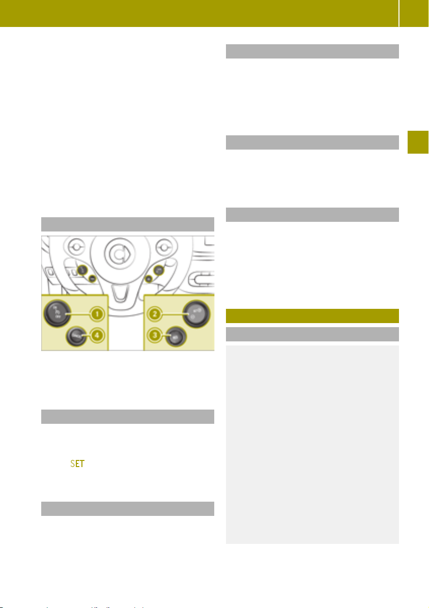
Charging the high-voltage battery
61
Cruise control does not brake the vehicle
automatically.
R
reduce the vehicle speed by applying the
brakes.
Speed regulation is canceled when the following occur:
R
braking (including the parking brake)
R
ESP®intervention
On downhill gradients or when accelerating
briefly, cruise control may interrupt speed
regulation. Afterwards, the set speed is
applied again.
Cruise control is ready for use at speeds
above 25 mph (40 km/h).
Activating cruise control
Interrupting cruise control
X
Press ± button ?.
The stored speed can be accessed again
later.
The stored speed is deleted when the engine
is switched off.
Calling up the stored speed
X
Press ° button =.
X
Remove your foot from the accelerator
pedal.
Deactivating cruise control
X
Press button : to the OFF center position.
The ¯ symbol in the instrument cluster
display goes out. The stored speed is
deleted.
The stored speed is deleted when the engine
is switched off.
Charging the high-voltage battery
Please note
>> Driving.
X
Press the upper section of button :.
The ¯ symbol appears in the instrument cluster display.
Storing the current speed
X
Press ® button ;.
X
Remove your foot from the accelerator
pedal.
¯ SET
appears in the instrument cluster
display.
Adjusting the stored speed
X
Press (+) or (-) button ; until the desired
speed is reached.
DANGER
G
The vehicle's high-voltage electrical system is under high voltage. If you modify
components in the vehicle's high-voltage
electrical system or touch damaged components, you may be electrocuted. The
components in the vehicle's high-voltage
electrical system may be damaged in an
accident, although the damage is not visible. There is a risk of fatal injury.
Following an accident, do not touch any
high-voltage components and never modify the vehicle's high-voltage electrical
system. Have the vehicle towed away after
an accident and the vehicle's high-voltage
electrical system checked by a qualified
specialist workshop.
Z

Charging the high-voltage battery
62
WARNING
G
In the event of a vehicle fire, the internal
pressure of the high-voltage battery can
exceed a critical value. In this case flammable gas escapes through a ventilation
valve on the underbody. The gas can
ignite. There is a risk of injury.
Leave the danger zone immediately. Secure
the danger area at a suitable distance,
whilst observing legal requirements.
DANGER
G
Connecting the charging cable to the
mains supply via incorrectly installed
mains sockets or by means of adapters,
>> Driving.
extension cables or similar could cause a
fire or an electric shock. There is a risk of
fatal injury.
To avoid hazardous situations, observe the
following:
R
Only connect the charging cable to
mains sockets:
-
which have been properly installed
and
-
which have been inspected by a qualified electrician
R
For safety reasons, only use the charging cables supplied with the vehicle, or
charging cables which have been
approved for use with this vehicle.
R
Never use a damaged charging cable.
R
Do not use:
-
extension cables
-
extension reels
-
multiple sockets
R
Never use socket adapters to connect the
charging cable to the mains socket. The
only exception being if the adapter has
been tested and approved by the manufacturer for charging the high-voltage
battery of an electric vehicle.
R
Observe the safety notes in the operating instructions for the socket adapter.
DANGER
G
Connecting the charging cable to the wallbox via an incorrectly installed wallbox or
adapter, extension cable or similar could
cause a fire or an electric shock. There is a
risk of fatal injury.
To avoid hazardous situations, observe the
following:
R
Only connect the charging cable to a
wallbox that:
-
is installed correctly and
-
has been inspected by a qualified
electrician
R
For safety reasons, only use charging
cables that have been tested and
approved by the manufacturer for
charging the high-voltage battery in an
electric vehicle.
R
Never use damaged charging cables.
R
Do not extend the charging cable.
R
Do not use an adapter.
R
Always observe the safety notes in the
wallbox's operating instructions.
The vehicle's high voltage electrical system
is under high voltage.
R
Do not tamper with the high-voltage components or the orange cables of the highvoltage electrical system.
R
Do not touch the high-voltage components
or the orange cables of the high-voltage
electrical system in a vehicle which has
been involved in an accident.
R
Do not touch damaged components or the
damaged orange cables of the high-voltage electrical system.
R
Do not remove the covers of the high-voltage electrical system components which
are marked with a yellow warning sticker.
For safety reasons, only use the charging
cable which is supplied with the vehicle or
which has been approved by smart for this
vehicle.
Do not clean the vehicle whilst charging.

Charging the high-voltage battery
63
Useful information
Method of operation
The vehicle is equipped with a high-voltage
battery for driving. The high-voltage battery stores the energy needed to operate the
electric motor and releases it again.
The electric motor uses energy stored in the
high-voltage battery for pulling away and
accelerating.
In overrun mode, kinetic energy is converted
into electrical energy by recuperation and
stored in the high-voltage battery.
The high-voltage battery can be charged as
follows:
R
by recuperation while the vehicle is in
motion
R
with the suitable charging cable at a mains
socket while the vehicle is stationary
R
with the suitable charging cable at a wallbox while the vehicle is stationary
R
with the suitable charging cable at a
charging station while the vehicle is stationary
Not all charging variants are available in all
countries.
The high-voltage battery can be charged in a
voltage range from 100 V to 240 V.
If possible only charge the high-voltage
i
battery when the charge is below 80%.
Charge the high-voltage battery at the
latest when the charge falls below 20%.
Discharged high-voltage battery
The high-voltage electrical system switches
off if the high-voltage battery is completely
discharged. This protects the high-voltage
battery from exhaustive discharge.
Switching the ignition on and then off
i
can reactivate the high-voltage electrical
system temporarily. This allows the vehicle to be parked safely.
Do not allow the vehicle's high-voltage battery to remain in a discharged or almost fully
discharged state for more than 14 days. You
can check the condition of charge in the
charge level display (
Y page 57).
Extreme outside temperatures
The efficiency of the high-voltage battery is
temperature-dependent and is significantly
reduced at low or very high temperatures. In
addition, the electrolytes used may freeze at
very low temperatures.
The LED ring in power display shows the
power output available (
Y page 57).
Energy consumption and range
The available energy in the high-voltage
battery is fundamentally reduced by the following factors:
R
low outside temperatures
R
operating the air-conditioning system or
heating
R
switching on electrical consumers
Low outside temperature and prolonged
periods of inactivity without charging can
have the following effects:
R
the high-voltage battery output is significantly reduced
R
charging periods may be longer
R
range can be significantly reduced
In extreme cases, it may not be possible to
start the vehicle as a result. You should
therefore always ensure that the high-voltage battery is fully charged or that the
charging cable is connected when parking
the vehicle for an extended period of time at
low outside temperatures.
As the gets older, the capacity of the highvoltage battery will diminish in the course of
its lifetime. This reduces the maximum range
and the maximum acceleration.
Battery care
Observe the following notes on battery care:
R
avoid storing and transporting the vehicle
at high temperatures and over an extended
period of time (e.g. transporting it in a
container)
R
connect the vehicle to a power supply
when parking it for an extended period of
time
R
temperatures below Ò13 ‡ (Ò25 †) for more
than seven days can cause irreversible
damage to the vehicle due to frost damage
>> Driving.
Z

Charging the high-voltage battery
64
Conditions of use
Observe the information on exceptions and
limitations in the warranty documentation
and in the Maintenance Booklet.
Voltage surge protection device
Voltage surges in the mains supply can
!
damage the vehicle. The vehicle is therefore equipped with a device which protects
it from voltage surges in the mains supply.
This device may be triggered during
severe thunderstorms, for example, and
may lead to the building's fuse being tripped and an interruption in the power supply. These functions protect the vehicle.
After the building fuse is switched on
>> Driving.
again, the charging process resumes automatically. Following an interruption in the
power supply without the building's fuse
being tripped, it may take up to 10 minutes
for charging to resume automatically.
After the device has triggered, switch the
building's fuse unit on again. Otherwise, the
charging process will not resume.
Heat generated by the charging cable
and charging cable connector
Charging cables and charging cable connectors may heat up during the charging process at a mains socket.
In the following cases, the rise in temperature is within the permitted limits:
R
infrastructure of the mains power supply
and the charging cable are intact
R
instructions for handling the charging
cable and controls on the charging cable
are followed
If an increase in temperature to above the
permitted limits does take place, check the
infrastructure of the mains power supply.
Understanding the vehicle socket
Overview vehicle socket
Charge socket flap
:
Socket cap
;
Catch
=
Indicator lamp
?
Vehicle socket
A
Indicator lamp on the vehicle socket
The indicator lamp on the vehicle socket has
the following meaning:
Indicator lamp
Flashes
green slowly
Lights up
green
Flashes
orange
slowly
Flashes
orange
Flashes red
quickly
High-voltage battery is
being charged.
High-voltage battery is
fully charged.
Vehicle waiting for charging to start.
Vehicle is paused from
charging.
A malfunction occurred
during charging.

Charging the high-voltage battery
65
Charging the battery using a mains
socket
Useful information
Charging cable
Only use the charging cable to charge the
!
high-voltage battery. Do not use the
charging cable for other purposes. It may
otherwise be damaged.
The charging cable for connection to a mains
socket is included in the scope of delivery.
Only use the charging cable which is supplied with the vehicle and which has been
approved by smart for this vehicle.
For transportation, wrap the charging cable
around the control panel or secure it to the
control panel housing.
Control panel on charging cable
Do not leave the control panel on the charging cable hanging loose from a mains socket.
Otherwise, this could lead to a bad contact
with the mains socket and to malfunctions
when charging the vehicle.
Do not lift up or transport the control panel
by the charging cable connector or the mains
plug.
Indicator lamp :
Lights up
green
Flashes
orange
Indicator lamp ;
Lights up
green
Indicator lamp =
Lights up
green
Flashes
orange
Indicator lamp ?
Lights up
red
Value is set as the desired
charging current.
Depending on the mains
socket, the value cannot be
set as the desired charging
current.
Mains voltage is connected.
The high-voltage battery
can be charged.
High-voltage battery is
being charged.
Connection to the vehicle is
established.
The current at the control
panel is not correct. The
high-voltage battery cannot be charged.
>> Driving.
Indicator lamp, charge current setting
:
Indicator lamp, mains voltage
;
Indicator lamp, charging process
=
Indicator lamp, protection and control
?
module
Button for setting the charge current
A
The indicator lamps on the charging cable
have the following meaning:
Setting the charge current
WARNING
G
If the charge current draw via a mains
socket is too high during the charging
process, the external electrical system
may overheat. There is a risk of fire.
Before beginning the charging process,
check the maximum permissible charge
current locally. Consult a qualified expert
to do so where necessary.
If necessary, adjust your vehicle's settings.
An excessive charge current can blow a
!
fuse or lead to overheating of the external
power supply. Check whether the external
power supply is compatible with the set
charge current. If necessary, lower the set
Z
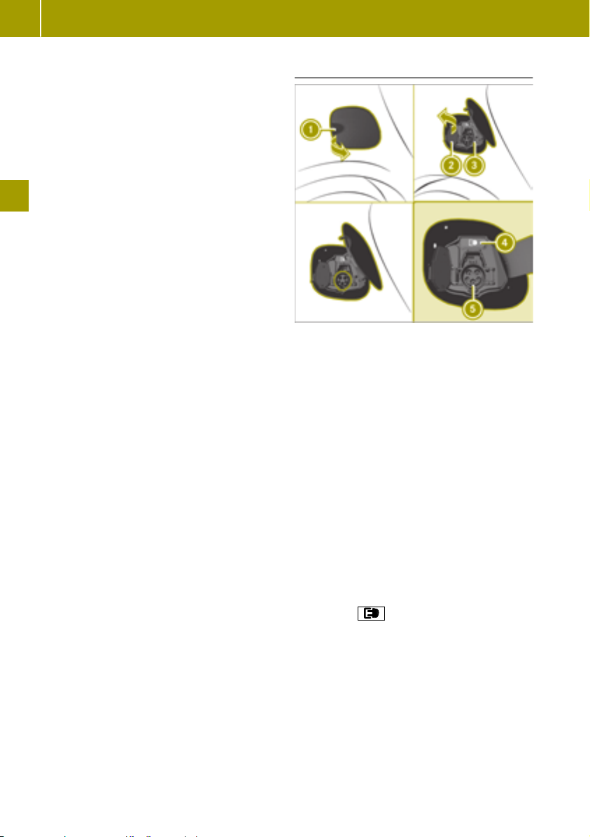
Charging the high-voltage battery
66
charge current or use another power
socket.
The value of the charge current used to
charge the high-voltage battery can be limited. This may protect the mains supply from
overloads.
The maximum setting value and the adjustment values may vary from country to country.
The preset default value is the minimum setting. This is the minimum charge current
available from the mains supply.
If the charging cable remains in the mains
socket after charging, the value set will be
adopted the next time you start charging. If
the charging cable is disconnected from the
mains socket, the value will be reset to the
>> Driving.
minimum setting the next time you start
charging.
X
Check the maximum permissible charge
current for the particular mains socket.
X
Plug the cable connector into the mains
socket.
You have one minute to set the charge current.
X
Press button A repeatedly until the indicator lamp in the desired setting lights up
green.
The desired value is set.
After one minute, the charge current can
i
only be set by restarting. To do so, remove
the charging cable from the mains supply
and reinsert it into the mains socket.
Connecting a charging cable
Charge socket flap
:
Socket cap
;
Catch
=
Indicator lamp
?
Vehicle socket
A
X
Switch the ignition off.
X
Engage transmission position j.
X
Open charge socket flap : (Y page 64).
X
Release lock = on socket cap ;.
Socket cap ; opens.
X
Insert the mains plug into the mains socket
as far as it will go.
X
Set the desired charge current
X
Insert the charging cable connector into
vehicle socket A as far as it will go.
The high-voltage battery is being
charged.
The high-voltage battery is fully charged
when the
cle socket lights up green.
indicator lamp on the vehi-
The vehicle must not be moved during
i
charging. The gear lever cannot be moved
from position j.
The engine cooling system and battery
i
cooling system may audibly switch on
during charging depending on the temperature.
If charging the vehicle's high-voltage
i
battery is taking longer than usual, check
the maximum charge current settings.
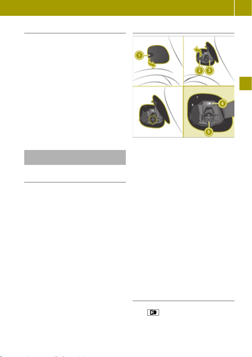
Charging the high-voltage battery
67
Removing the charging cable
Always disconnect the charging cable
!
from the vehicle socket first. Disconnecting the charging cable from the stationary
socket first could damage the charging
cable connector.
The charging cable can be removed when the
high-voltage battery is completely charged
or charging has to be interrupted.
X
Disconnect the charging cable from vehicle socket A.
X
Close socket cap ;.
X
Close charge socket flap :.
X
Disconnect the charging cable from the
mains socket.
X
Stow the charging cable safely in the
charging cable bag (
Y page 68).
Charging the batteryat a charging station or wall box
Charging stations without communications functionality
Charging stations without communications
functionality must be activated before
charging, e.g. by using an RFID card. To do
this, please observe the notes of the operator
of the charging station.
Connecting a charging cable
Charge socket flap
:
Socket cap
;
Catch
=
Indicator lamp
?
Vehicle socket
A
X
Switch the ignition off.
X
Engage transmission position j.
X
Open charge socket flap : (Y page 64).
X
Release locking mechanism = on socket
cap ;.
Socket cap ; opens.
X
Insert the charging cable connector into
vehicle socket A as far as it will go.
The high-voltage battery is being
charged.
>> Driving.
The vehicle must not be moved during
i
charging. The gear lever cannot be moved
from position j.
The engine cooling system and battery
i
cooling system may audibly switch on
during charging depending on the temperature.
Removing the charging cable
X
Press the % button on the SmartKey.
The
socket A goes out.
X
Disconnect the charging cable from vehicle socket A.
indicator lamp ? above vehicle
Z

Charging the high-voltage battery
68
X
Close socket cap ;.
X
Close charge socket flap :.
Storing the charging cable
The charging cable must be stowed in the
!
charging cable bag only to prevent it from
being thrown around inside the vehicle.
X
Stow the charging cable in the charging
cable bag.
The charging cable bag is located in the
Y page 125).
trunk (
>> Driving.
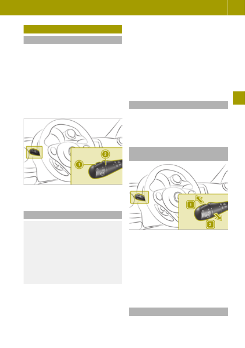
Switching on the lighting
Useful information
The driver must ensure that the light settings match the current weather, light and
traffic conditions.
For reasons of safety, smart recommends that
you drive with the daytime driving lights or
low beam headlamps switched on even during the daytime.
A warning tone sounds if the lights are still
on when you leave the vehicle.
In some countries, operation of the headlamps varies due to legal requirements and
self-imposed obligations.
Switching on the lighting
X
Turn combination switch control : to the
à position.
If one or more of the following eventualities
occurs, the lights are switched off automatically:
R
the engine is switched off
R
the driver's door is opened
R
the vehicle is locked
R
the high-beam headlamps are not
switched on when the vehicle is stationary
Switching on the low-beam headlamps
X
Turn combination switch control : to the
L position.
The L indicator lamp lights up in the
instrument cluster.
Switching the high-beam headlamps
on or off
69
Combination switch control
:
Marking
;
Activating automatic headlamp mode
WARNING
G
When the light switch is set to Ã, the
low-beam headlamps may not be switched
on automatically if there is fog, snow or
other causes of poor visibility due to the
weather conditions such as spray. There is
a risk of an accident.
In such situations, turn the light switch to
L.
While the engine is running, the light setting
is selected automatically according to the
brightness of the ambient light. Ã controls the daytime running lights, parking
lamps and low beam headlamps. The automatic headlamp feature is only an aid. The
driver is responsible for the vehicle's lighting at all times.
The engine must be running.
X
Turn the combination switch control to the
à or K position.
X
To switch on: press the combination switch
in the direction of arrow 1.
X
To switch off: move the combination switch
back to its original position.
The K indicator lamp in the instrument
cluster lights up when the high-beam headlamps are switched on.
Using the high-beam flasher
X
Pull the combination switch in the direction of arrow 2.
Z
>> Ensuring good visibility.

Using the interior lighting
70
Switching the parking lamps on
X
Turn combination switch control : to the
T position.
Canada only: the parking lamps are only
switched on when the engine is switched off.
When the engine is running, the low beam
headlamps are switched on.
Switching the fog lamps and rear fog
lamp on and off
Only vehicles with front fog lamps are equipped with the "fog lamps" function.
Combination switch middle ring
:
Marking
;
>> Ensuring good visibility.
The ignition and either the parking lamps or
low beam headlamps must be switched on in
order to switch the fog lamps on.
The engine must be started and either the
parking lamps or low beam headlamps
switched on in order to switch the rear fog
lamp on.
X
To activate or deactivate manually, turn
combination switch middle ring : to the
desired marking:
R
O fog lamps
R
R rear fog lamp
After releasing, the combination switch middle ring returns automatically to the neutral
position.
The fog lamps and rear fog lamp also go out
automatically in the following situations:
R
the lights are switched off
R
the engine is switched off and the control
is in the à position
Using the cornering light function
Only vehicles with the LED & Sensor package
are equipped with the cornering light function.
The cornering light function uses the front
fog lamp to improve the illumination of the
road in the direction in which you are turning, enabling better visibility in tight bends,
for example.
The following conditions must be fulfilled for
the cornering light function to switch on
automatically:
R
the low-beam headlamps are switched on
R
the vehicle is moving at less than 25 mph
(40 km/h)
R
the turn signal is switched on or the steering wheel is turned
Using the interior lighting
Switching the interior lighting on and
off
The interior lights go on when you unlock the
doors.
The interior lights switch off in the following
situations:
R
a door is opened and 15 minutes have
passed
R
all doors are closed, the vehicle has been
locked and 15 seconds have passed
R
all doors are closed, the vehicle has not
been locked and 4 minutes have passed
R
the engine has been started
The interior lighting can be activated when a
door is open. After closing the doors, the
interior lighting goes out.
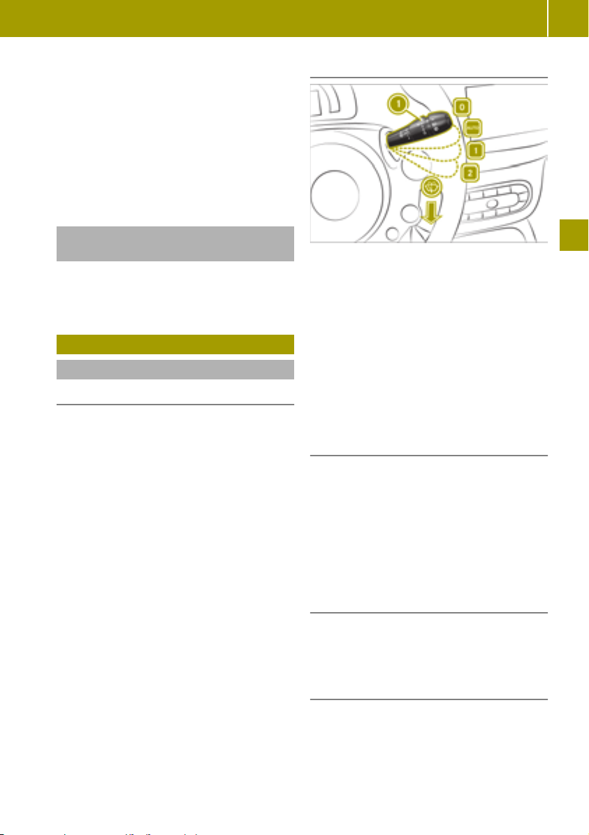
X
Press switch : to activate or deactivate
the left-hand reading lamp.
X
Move switch ; to the desired position:
R
interior lighting switched on
R
interior lighting controlled automatically
R
interior lighting switched off
X
Press switch = to activate or deactivate
the right-hand reading lamp.
Adjusting the ambient lighting (color
display)
On-board computer with color display: the
ambient lighting is set in the on-board com-
Y page 88).
puter (
Using the windshield wiper
Switching on the windshield wiper
Please note
Do not operate the windshield wipers
!
when the windshield is dry, as this could
damage the wiper blades. Moreover, dust
that has collected on the windshield can
scratch the glass if wiping takes place
when the windshield is dry.
If it is necessary to switch on the windshield wipers in dry weather conditions,
always use washer fluid when operating
the windshield wipers.
Vehicles with a rain sensor: if the wind-
!
shield becomes dirty in dry weather conditions, the windshield wipers may be
activated inadvertently. This could then
damage the windshield wiper blades or
scratch the windshield.
For this reason, you should always switch
off the windshield wipers in dry weather.
Make sure that the front windshield wip-
!
ers are free of ice. The wiper motor could
otherwise overheat.
Wiper blades are subject to wear and tear.
smart recommends replacing the wiper
blades twice a year. Worn or damaged wiper
blades cause smearing on the windshield. On
vehicles with a rain sensor, malfunctions are
then possible.
Using the windshield wiper
Switching continuous wipe on and off
Control for wipe frequency
:
Continuous wipe, off
u
Automatic wipe
©
Continuous wipe, slow
1
Continuous wipe, fast
2
Wiping with washer fluid
î
The ignition must be switched on in order to
operate the windshield wiper.
X
Press the combination switch down or up
to the desired position.
Automatic wipe (vehicles with rain sensor)
The rain sensor is only an aid. The driver is
responsible for ensuring good visibility at
all times.
X
Press the combination switch to the ©
position. In automatic wipe mode, the
appropriate wiping frequency is set
according to the intensity of the rain.
X
Use control : to set the wipe frequency.
Switching on intermittent wiping
X
Press the combination switch to the ©
position.
X
Use control : to set the wipe frequency.
Wiping with washer fluid
X
Pull the combination switch in the direction of arrow î.
71
>> Ensuring good visibility.
Z
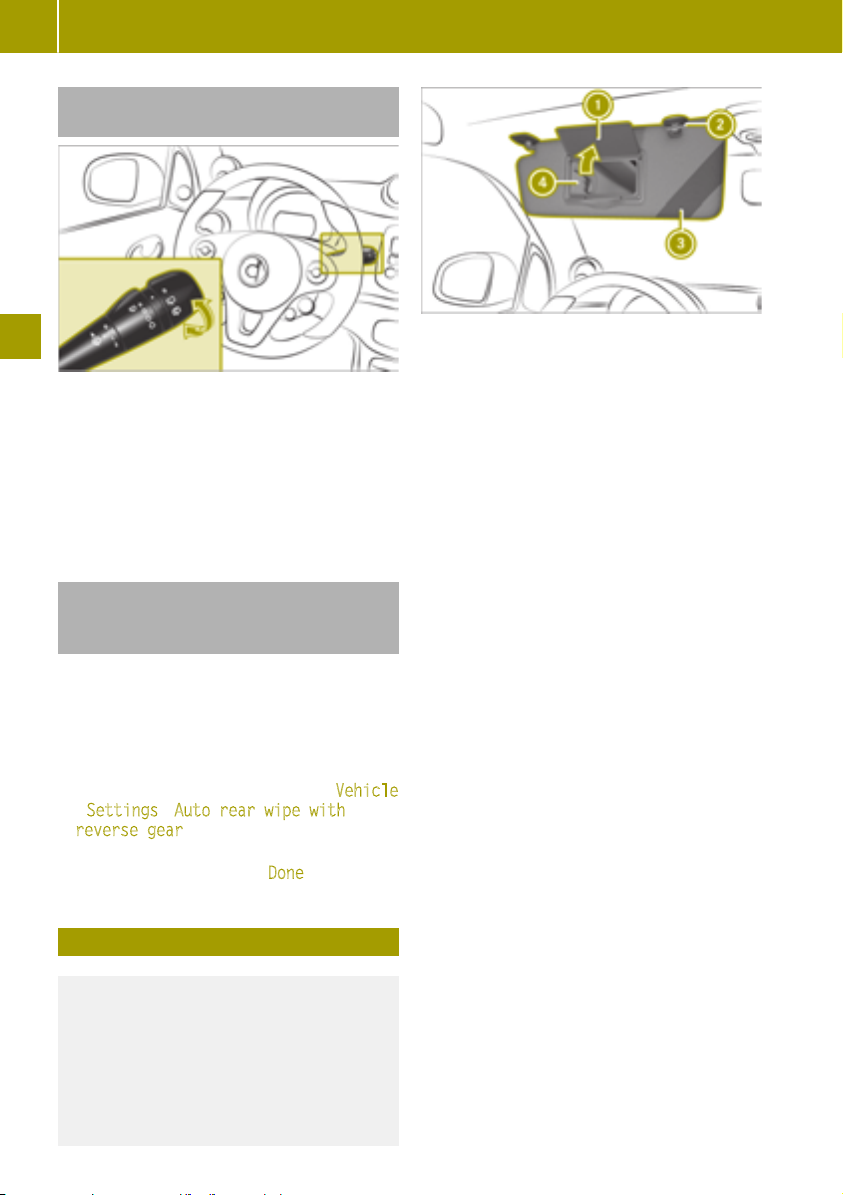
Folding the sun visor to the side
72
Switching the rear window wiper on
and off (smart fortwo coupe)
To operate the rear window wiper, the ignition must be switched on.
X
Turn the outer control on the combination
switch to the desired position:
R
$ Rear window wiper off
R
è Rear window wiper on
R
î Wipes with washer fluid
Switching the rear window wiper on
and off when in reverse gear (smart
fortwo coupe)
>> Ensuring good visibility.
You can switch the "Automatic rear window
wiper when reversing" setting on or off in the
smart Media-System. The rear window wiper
operates automatically for a short while
when the ignition and the windshield wiper
are switched on and reverse gear is engaged.
X
In the smart Media-System, select Vehicle
> Settings > Auto rear wipe with
reverse gear.
The selected setting is highlighted.
X
Confirm the setting with Done.
Mirror cover
:
Bracket
;
Retaining strap
=
Vanity mirror
?
X
Fold the sun visor down.
X
Pull the sun visor out of retainer ;.
X
Fold the sun visor to one side
Folding the sun visor to the side
WARNING
G
If the mirror cover of the vanity mirror is
folded up when the vehicle is in motion,
you could be blinded by incident light.
There is a risk of an accident.
Always keep the mirror cover folded down
while driving.

Understanding the reversing feature
Locking and unlocking the doors from
the inside
Using the door handle to unlock the
door
X
Pull door handle :.
If the vehicle has previously been locked
with the SmartKey, opening a door from the
inside will trigger the anti-theft alarm system. To disable the alarm, switch on the ignition.
Centrally locking and unlocking the
vehicle from the inside
WARNING
G
If children are left unsupervised in the
vehicle, they could:
R
open the doors, thus endangering other
people or road users.
R
get out and disrupt traffic.
R
operate the vehicle's equipment.
Additionally, children could set the vehicle in motion if, for example, they:
R
release the parking brake.
R
shifting the automatic transmission out
of park position P
R
Start the engine.
There is a risk of an accident and injury.
When leaving the vehicle, always take the
SmartKey with you and lock the vehicle.
Never leave children or animals unattended in the vehicle. Always keep the SmartKey out of reach of children.
X
To lock: press button :.
When the doors are locked, indicator
lamp ; lights up.
X
To unlock: press button :.
Activating and deactivating the automatic locking feature
The activated automatic locking feature
locks the vehicle automatically when the
ignition is switched on and the vehicle is
moving.
X
When the engine is running, press and
hold button : for five seconds until a tone
sounds.
When the automatic locking function is
activated, the locking mechanism engages
audibly when you pull away. When the
automatic locking function is deactivated,
no sound occurs.
Understanding the reversing feature
Vehicles with automatic operation: the side
windows are equipped with an automatic
reversing feature. If a solid object blocks or
restricts a side window from closing during
automatic operation, the side window opens
again automatically. During the manual
closing process, the side window only opens
again automatically after the corresponding
switch is released. The automatic reversing
feature is only an aid. The driver is responsible for operating the side windows safely.
73
>> Feeling comfortable in the vehicle interior.
Z

Opening and closing the windows
74
WARNING
G
The reversing feature does not react:
R
to soft, light and thin objects, e.g. small
fingers
R
while resetting
This means that the reversing feature cannot prevent someone being trapped in
these situations. There is a risk of injury.
Make sure that no body parts are in close
proximity during the closing procedure. If
someone becomes trapped, press the
switch to open the side window again.
Opening and closing the windows
Please note
WARNING
G
While closing the side windows, body parts
in the closing area could become trapped.
There is a risk of injury.
When closing make sure that no parts of
the body are in the closing area. If somebody becomes trapped, release the switch
or press the switch to open the side window
again.
WARNING
G
If children operate the side windows they
could become trapped, particularly if they
are left unsupervised. There is a risk of
injury.
When leaving the vehicle, always take the
SmartKey with you and lock the vehicle.
Never leave children unsupervised in the
>> Feeling comfortable in the vehicle interior.
vehicle.
poses an increased risk of injury or even
fatal injury.
Make sure that no parts of the body are in
the closing area. To stop the closing process, release the switch or push the switch
again to reopen the side window.
Vehicles with automatic operation: the
switches for both side windows are located
on the driver's door. There is also a switch for
the front-passenger window on the frontpassenger door. The switch on the driver’s
door takes precedence.
Opening and closing the windows
Vehicles with automatic operation
Left side window
:
Right side window
;
WARNING
G
If you close a side window again immediately after it has been blocked or reset, the
side window closes with increased or maximum force. The reversing feature is then
not active. Parts of the body could be trapped in the closing area in the process. This
Vehicles without automatic operation
X
To open: press the switch.
X
To close: pull the switch.

Using the soft top (smart fortwo cabrio)
Opening and closing windows fully in
automatic mode
Vehicles with automatic operation:
X
To open the windows fully, press the
switch beyond the point of resistance and
release it.
X
To close the windows fully, pull the switch
beyond the point of resistance and release
it.
X
To stop automatic operation, press the
switch again.
Using the soft top (smart fortwo cabrio)
Please note
Make sure that objects are not stacked too
!
high in the cargo compartment. They may
be damaged when the rear soft top is
opened or closed.
The procedure for removing, installing and
stowing the side bars is described below. The
QR code is a link to a video clip that demonstrates the procedure.
75
WARNING
G
During opening and closing of the folding
top or rear soft top, body parts may become
trapped for example, by the roof mechanical system. There is a risk of injury.
Ensure that no parts of the body are in the
immediate vicinity of moving parts during
the closing or opening process. Release the
switch immediately if somebody becomes
trapped.
When transporting long objects in the
!
vehicle interior when the folding top is
closed, make sure that the objects do not
push against the folding top.
When transporting objects that protrude
out of the rear of the vehicle, make sure
that the objects do not rest on the rear soft
top latch (bracket). Make sure that no
sharp edged parts come into contact with
the soft top or the rear window during
loading.
Do not place flatly distributed loads with a
weight of more than 75 kg on the folded
down rear soft top.
Make sure that the high-mounted brake
lamp is not covered.
Do not obstruct the latch openings of the
!
soft top system. Stow the side bars only in
the designated stowage well of the tailgate.
Opening and closing the soft top
To open or close the soft top, the ignition
must be switched on.
X
To open: press the switch to position ;
until the soft top is in the desired position.
Press switch ; again to fully open the soft
top.
X
To close: press the switch to position :
until the soft top is in the desired position.
It is possible to open or close the soft top
while driving up to the maximum design
speed. In poor weather and at high speeds, it
is possible that electric locking when closing
is not reliable. If this is the case you must
reduce the speed and, if necessary, press the
switch again to close the soft top.
>> Feeling comfortable in the vehicle interior.
Z

Using the soft top (smart fortwo cabrio)
76
Opening the soft top (using the SmartKey)
X
Press and hold the é button on the
SmartKey.
Removing the side bars
X
Open the soft top
X
Open the doors and tailgate.
X
To release: slide lever : back.
The side bar is unlocked.
X
Push lever : back again and remove side
bars ;.
Please note:
R
only use the stowage space to store the
side bars
R
always place both side bars in the stowage
space
Observe the notice on the stowage well.
X
Release fastening straps : on the stowage
space and guide the locking mechanism
with your hand until the fastening straps
are released.
X
Open cover ;.
X
Store the side bars as shown (observe
markings L and R on the side bars and the
stowage compartment for the left and right
side bars):
Stowing the side bars
WARNING
G
If you transport the side bars without
securing them, they may be thrown around
in the event of an accident, braking or sudden changes in direction. There is a risk of
injury.
Always stow the side bars in the designated stowage well and close the stowage
well lid.
>> Feeling comfortable in the vehicle interior.
When the soft top is folded down, theft of
!
the side bars is possible. Therefore, remove
the side bars and stow them in the cargo
compartment or close the soft top.
If you load the stowage space it could be
!
damaged.
Never stow heavy objects on the stowage
space or sit on it.
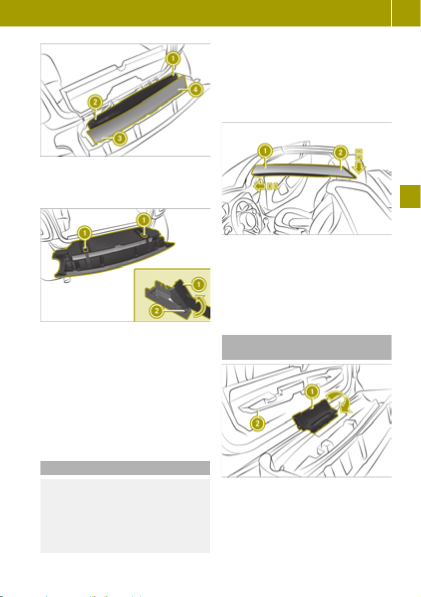
Side bar, front left
:
Side bar, rear left
;
Side bar, front right
=
Side bar, rear right
?
Using the soft top (smart fortwo cabrio)
X
Open the doors and tailgate.
X
Release the fastening straps on the stowage space and guide the locking mechanism with your hand until the fastening
straps are released.
X
Open the cover.
X
Remove the side bars.
X
Insert the side bar from the stowage compartment marked L on the left side at front
end :.
X
Press down rear end of side bar ; until it
engages twice.
X
Install the side bar from the stowage compartment marked R on the right-hand side.
77
X
Close the cover.
The cover must audibly engage.
X
Secure both fastening straps with tensioner : on rear detent ;.
The red surfaces at the side must no longer
be visible. An audible click can be heard
upon engaging.
X
Close the tailgate.
X
If the tailgate does not close properly,
check if the side bars have been stored as
specified.
Mounting the side bars
WARNING
G
If the side bars are incorrectly mounted
they may become loose during the journey
and endanger other road users. There is a
risk of an accident and injury.
Mount the side bars as described.
Closing the stowage well without the
side bars
X
Move folding mechanism : in the direction of the arrow.
X
Close cover ;.
>> Feeling comfortable in the vehicle interior.
Z

Operating the climate control system
78
X
Secure both fastening straps with tensioner : on front detent ;.
The red surfaces at the side must no longer
be visible. An audible click can be heard
upon engaging.
X
Close the tailgate.
Installing and removing the wind
screen (smart fortwo cabrio)
Installing the wind screen
Removing the wind screen
X
Unhook loops A from hooks ? in the side
paneling.
X
Unhook recesses : from hooks ; on the
roll bar.
Operating the climate control system
Useful information
The climate control system is only available
when the ignition is switched on.
If the climate control system is deactivated,
the air supply and circulation are switched
off. The windows could fog up. You should
therefore switch off the climate control system for brief periods only.
In air-recirculation mode, only the air inside
the vehicle is recirculated and no fresh air is
introduced. This is useful in a tunnel or when
there are unpleasant odors outside the vehicle. In air-recirculation mode, the windows
may fog up more quickly, particularly when
the outside temperature is low. Therefore,
switch on air-recirculation mode only
briefly.
The integrated filter in the climate control
system keeps out most particles of dust as
well as pollen. The filter reduces the amount
of air supplied to the vehicle interior. For this
reason, you should always observe the interval for replacing the filter.
>> Feeling comfortable in the vehicle interior.
X
Open the soft top completely.
X
Attach recesses : of wind screen = on to
hooks ; on the roll bar.
X
Attach loops A on to hooks ? in the side
paneling.
Operating the automatic climate control
Switching the automatic climate control
system on and off

Operating the climate control system
79
The ignition must be switched on in order to
operate the blower. The engine must be running in order to operate all the functions of
the automatic climate control system.
X
To switch on: press the à button.
The indicator lamps below à and
¿ light up.
X
To switch off: press the ^ button.
The indicator lamp below ^ lights up.
Setting the temperature
X
Move the slider in small increments to the
left or right.
In automatic mode, the set temperature is
maintained at a constant level. The air distribution and blower speed are regulated
automatically.
Switching the air distribution on and off
X
Press one or more of the ¯, P, O
buttons.
R
¯ Defroster vents
R
P Center and side air vents
R
O Footwell vents
Increasing the blower speed
X
Press the K button.
Decreasing the blower speed
X
Press the I button.
Activating/deactivating air-recirculation mode
X
Press the À button.
The indicator lamp above À lights up
when air-recirculation mode is activated.
Switching "Cooling with air dehumidification" on or off
The "Cooling with air dehumidification"
function cools and dehumidifies the air
inside the vehicle during warm weather.
The engine must be running in order to use
"Cooling with air dehumidification".
X
To switch on: press the K and
¿ button.
The indicator lamp below ¿ lights up
when the function is activated.
In damp weather switch off the "Cooling with
air dehumidification" function only briefly.
Otherwise the windows will fog up faster.
Defrosting the windshield
X
Press the ¬ button.
The indicator lamp above ¬ lights up
when the windshield is being defrosted.
Use this setting only until the windshield is
clear again.
Defrosting the rear window
When the rear window defroster is activated,
the exterior mirrors are also heated.
X
Press the ¤ button.
The indicator lamp above ¤ lights up
when the rear window defroster is activated.
Use this setting only until the rear window is
clear again.
Drying windows that are fogged up on the
inside
X
Press the ¿ button.
X
Press the à button.
X
If the windows are still fogged up, press
the ¬ button.
Use this setting only until the windows are
clear again.
Drying windows that are fogged up on the
outside
X
Switch on the windshield wipers.
X
Press the ¬ button.
Use this setting only until the windows are
clear again.
Setting the pre-entry climate control at
departure time using the on-board computer
The "Pre-entry climate control at departure
time" function“ heats or cools the vehicle
>> Feeling comfortable in the vehicle interior.
Z

Activating/deactivating the seat heating and steering wheel heating
80
interior before the scheduled departure time.
The climate control runs until approx.
10 minutes after the set departure time.
The vehicle must be connected to the charger
in order to activate pre-entry climate control. The battery charge and the charge output of the high-voltage battery must be sufficient.
If pre-entry climate control cannot be operated, a display message is shown in the onboard computer.
X
Call up Pre-ent. Clim. Ctrl. & Charge
in the on-board computer.
X
Press a.
X
Select one of the following settings:
R
no Preselection
The pre-entry climate control is deactivated.
R
Two stored departure times
X
Departure time > select Activate to activate the stored departure time.
X
Departure time > select Change to change
the settings of a stored departure time.
X
Set the value
If instant charging is selected, the
i
high-voltage battery is charged regardless of the cost information. A part of the
charging may not be conducted until
one to two hours before the departure time,
in order for temperature control of the
high-voltage battery to be carried out for
the intended departure time.
Setting the air vents
Please note
WARNING
G
Very hot or very cold air can flow from the
>> Feeling comfortable in the vehicle interior.
air vents. This could result in burns or
frostbite in the immediate vicinity of the
air vents. There is a risk of injury.
Make sure that all vehicle occupants
always maintain a sufficient distance to
the air outlets. If necessary, redirect the
airflow to another area of the vehicle interior.
WARNING
G
If you spray cleaning products or disinfectant into the ventilation system of the
vehicle, this could ignite. There is a risk of
fire.
Never spray these or any other substances
into the ventilation system. Always have
work on the ventilation system carried out
at a qualified specialist workshop.
Keep the following rules in mind for optimal
climate control:
R
Keep the air slots between the service
cover and windshield clear of blockages.
R
Do not cover the vents or ventilation grilles
in the vehicle interior.
R
Open the air vents fully.
Opening and closing the air vents
X
To open: turn vent 1 outwards.
X
To close: turn vent 2 inwards.
Directing the air vents
X
Turn the air vents upwards, downwards, to
the left or to the right as desired.
Activating/deactivating the seat heating and steering wheel heating
WARNING
G
Repeatedly switching on the seat heating
can cause the seat cushion, the backrest
pad and parts of the steering wheel to
become very hot. The health of persons

Using the accessories
81
with limited temperature sensitivity or a
limited ability to react to higher temperatures may be affected or they may even
suffer burn-like injuries. There is a risk of
injury.
Therefore, do not switch the seat heating
on repeatedly.
Heat accumulation can occur if the seat
!
heating is switched on and there are
objects or underlays placed on the seats,
e.g. seat cushions or child seats.
This can lead to damage to the seat surface.
Make sure that no objects or underlays are
placed on the seats when the seat heating
is switched on.
The seat heating only works when the ignition is switched on. Vehicles with the Winter
package are additionally equipped with the
"Steering wheel heating": function.
X
Press button =.
Indicator lamp ; lights up when seat
heating is activated.
Vehicles with the Winter package: steering
wheel heating : is also switched on when
the driver's seat heating is activated.
Using the accessories
Using the cigarette lighter
In addition, flammable materials can
ignite if:
R
the hot cigarette lighter falls
R
a child holds the hot cigarette lighter to
objects, for example
There is a risk of fire and injury.
Always hold the cigarette lighter by the
knob. Always make sure that the cigarette
lighter is out of reach of children. Never
leave children unsupervised in the vehicle.
The cigarette lighter only works when the
ignition is switched on.
X
Press cigarette lighter :.
When cigarette lighter : is hot, it pops up
automatically.
Using the ash tray
The cup holder in the center console is
!
not heat resistant. Before placing lit cigarettes in the ashtray, make sure that the
ashtray is fully inserted in the cup holder.
Make sure that lit cigarettes do not fall into
the cup holder.
Otherwise, the cup holder could be damaged.
>> Feeling comfortable in the vehicle interior.
WARNING
G
You can burn yourself if you touch the hot
heating element or the socket of the cigarette lighter.
Z

Using the accessories
82
X
To open: lift up cover :.
X
To close: push down cover :.
X
To remove: pull the ashtray up and out.
X
To insert: insert the ashtray into the cup
holder.
Using the 12 V socket
vehicle is jeopardized. There is a risk of an
accident.
Make sure that all objects in the vehicle are
stowed correctly, and that they cannot
enter the driver's footwell. Install the
floormats securely and as specified in
order to ensure sufficient clearance for the
pedals. Do not use loose floormats and do
not place floormats on top of one another.
X
Slide the driver's seat backward.
X
To install: press securing knobs : onto
retainers ;.
X
To remove: release securing knobs : from
retainers ;.
X
Turn the SmartKey to position 1 in the
ignition lock.
X
Lift up the cover of socket :.
X
Connect device.
The socket can be used for accessories up to a
maximum draw of 120 W (15 A).
If you use the socket for very long periods
when the engine is switched off, the 12 V
>> Feeling comfortable in the vehicle interior.
battery may discharge.
Installing and removing the floormats
WARNING
G
Objects in the driver's footwell can restrict
the pedal travel or obstruct a depressed
pedal. The operating and road safety of the

Using the rear view camera
83
Parking
Please note
WARNING
G
The automatic transmission switches to
neutral position N when you switch off the
engine. The vehicle may roll away. There is
a risk of an accident.
Before switching off the engine, always
switch to parking position P. Prevent the
parked vehicle from rolling away by
applying the parking brake.
Always secure the vehicle correctly
!
against rolling away. Otherwise, the vehicle or its drivetrain could be damaged.
Switching off the engine
X
Apply the parking brake.
X
Shift the transmission to position j.
X
Turn the SmartKey to position u in the
ignition lock and remove it.
X
On steep uphill or downhill gradients, turn
the front wheels towards the curb.
Using the rear view camera
Pay attention to people and obstacles
!
when maneuvering or parking the vehicle.
The driver is responsible in these situations.
If the rear of your vehicle is damaged,
!
consult a qualified specialist workshop
and have the rear view camera checked.
Objects that are not at ground level
!
appear further away than they actually
are, for example:
R
the bumper of the vehicle parked behind
R
the drawbar of a trailer
R
the ball coupling of a trailer tow hitch
R
the tail-end of a truck
R
slanted posts
Only use the image from the rear view
camera as a guide. You may otherwise
damage your vehicle and/or the object.
The rear view camera is a visual parking and
maneuvering aid. It shows the area behind
the vehicle with guide lines in the rear-view
mirror. The rear view camera is activated
automatically when the vehicle is backing
up.
Rear view camera : is located above the
license plate in the tailgate.
The area behind the vehicle is displayed as a
mirror image, as in the rear-view mirror.
The rear view camera might show a distorted
view of obstacles or show them incorrectly or
not at all if:
R
the obstacle is very close to the rear
bumper.
R
the obstacle is underneath the rear
bumper.
R
the obstacle is close to the tailgate handle.
R
the rear view camera is covered by additional accessories, e.g. a bicycle rack.
The function of the rear view camera might
be limited:
R
if the tailgate is open
R
if there is snow or heavy rain
R
in the dark
R
if a very bright light outshines the camera
R
if there is fluorescent light, e.g. from fluorescent lamps or LED lighting
R
if there is a rapid change of temperature
R
if the camera lens is dirty
Guide lines in different colors show the distance of obstacles from the rear of the vehicle.
>> Parking and getting out.
Z

Arming and disarming the anti-theft alarm system
84
Arming and disarming the anti-theft
alarm system
Useful information
The immobilizer prevents the vehicle from
being started without the correct SmartKey.
It is switched on and off automatically.
The anti-theft alarm system triggers a visual
and audible alarm if a door, the tailgate or the
service cover is opened.
The alarm is not switched off, even if,
Vehicle width including exterior mirrors
:
Green: approx. 59 in (1.50 m)
;
Yellow: approx. 27 in (0.7 m)
=
Red: approx.12 in (0.3 m)
?
>> Parking and getting out.
The distance specifications only apply to
objects that are at ground level.
Locking the vehicle
WARNING
G
If children are left unsupervised in the
vehicle, they could:
R
open the doors, thus endangering other
people or road users.
R
get out and disrupt traffic.
R
operate the vehicle's equipment.
Additionally, children could set the vehicle in motion if, for example, they:
R
release the parking brake.
R
shift the transmission out of park position P
R
start the vehicle's drive system.
There is a risk of an accident and injury.
When leaving the vehicle, always take the
SmartKey with you and lock the vehicle.
Never leave children or animals unattended in the vehicle. Always keep the SmartKey out of reach of children.
for example, you close the open door that has
triggered it.
Arming
X
Close the doors.
X
Close the tailgate.
X
Close the service cover.
X
Press the & button on the SmartKey.
The alarm system is armed after approximately 30 seconds.
Disarming and switching off the alarm
X
Press the % button on the SmartKey.
X
Press the & button on the SmartKey.
The turn signals flash twice.
Locking is confirmed by an audible signal.

Calling up displays
85
Overview of the on-board computer
Please note
WARNING
G
If you operate information systems and
communication equipment integrated in
the vehicle when driving, you may be distracted from the traffic situation. You
could also lose control of the vehicle. There
is a risk of an accident.
Only operate this equipment when the
traffic situation permits. If you are not
sure that this is possible, park the vehicle
paying attention to traffic conditions and
operate the equipment when the vehicle is
stationary.
WARNING
G
If the instrument cluster has failed or malfunctioned, you may not recognize function restrictions in systems relevant to
safety. The operating safety of your vehicle may be impaired. There is a risk of an
accident.
Drive on carefully. Have the vehicle
checked at a qualified specialist workshop
immediately.
Color display overview
Time
:
Digital Speedometer
;
Outside temperature display
=
Display field for display messages,
?
menus and lists
ECO mode
A
Remaining range
B
Transmission display
C
Cruise control
D
Calling up displays
Calling up displays (color display)
Calling up displays
>> Operating the on-board computer.
If the operating safety of your vehicle is
impaired, you must park the vehicle safely as
soon as possible. Consult a qualified specialist workshop.
The outside temperature is displayed on the
far right in the top bar. Drivers must pay
special attention to road conditions when
temperatures are around freezing point.
Changes in the outside temperature are displayed after a short delay.
After opening the door, the on-board computer is activated for approximately
15 minutes. To permanently activate the onboard computer, the ignition must be
switched on.
Color display
:
Left control panel
;
Z

Calling up displays
86
X
Briefly press 9 or : on left control
panel ;, to scroll forward or back.
X
Press and hold 9 or : on left control
panel ;, to directly call up the Distance
display.
The following displays can be called up one
after another:
R
Distance
R
Trip computer From Start
R
Trip computer From Reset
R
eco score from Start
R
Fuel consumption bar chart
R
Energy Flow
R
Pre-ent. Clim. Ctrl & Charge
R
Messages and Service
R
Settings
R
Digital Speedometer
>> Operating the on-board computer.
Distance display
If the ignition remains switched off for longer than four hours, the from
Start values in
the instrument cluster are reset.
eco score display
The eco score display provides feedback on
how economical the driver's driving behavior
Y page 57).
is (
If the ignition remains switched off for lon-
ger than four hours, the eco score display will
be automatically reset.
When the eco score display is reset, the from
Start trip computer in the smart Media-Sys-
tem and the eco score display are also reset
in the smart Media-System.
Fuel consumption bar chart display
Trip odometer
:
Odometer
;
Trip computer display
Elapsed time
:
Distance
;
Average speed
=
Average energy consumption
?
The data in the from
start of the journey, whilst the data in the
from Reset
menu refers to the last time the
submenu was reset.
Start menu refers to the
Energy consumption
:
Recuperation
;
The display shows the average energy consumption and recuperation over the previous
15 minutes.
Energy flow display
Total output
:
Output for electrical consumers
;

Setting values
87
The total output shows the driver the sum of
the energy currently flowing from the battery. The color of the battery shows whether
energy is being consumed or recuperated:
R
Battery symbol is orange: energy is being
consumed.
R
Battery symbol is green: energy is being
recuperated.
R
Battery symbol is gray: energy consumption and recuperation are equal or both at
0 kW.
The output for electrical consumers shows
the driver what output is needed to operate
electrical consumers such as climate control
systems or the radio. A greater range is achieved if the value is kept as low as possible.
Pre-entry climate control and charging
display
Time of the full charge
:
Condition of charge of the battery
;
Departure time
=
Smart-Charging
?
Charge current and charge output
A
An arrow underneath the battery indicates
the condition of charge of the battery at the
departure time. The condition of charge and
the time of complete charge are only predicted approximately. The moment at which
charging is completed cannot be displayed
when Smart-Charging is activated.
Information on the "Pre-entry climate control at departure time" function (
Y page 79).
Messages and service display
Message memory
:
Next service due date
;
The display shows the number of display
messages in the message memory and the
next service due date.
¯ indicates a minor service. ° indicates a major service.
To show the display messages, the ignition
must be switched on.
X
Press a to scroll through the display
messages.
Current information on the type of service
can be obtained at a smart center or a qualified specialist workshop.
Digital speedometer display
The display shows the digital speedometer.
The digital speedometer in the header is hidden.
Setting values
Setting values (color display)
Setting values
>> Operating the on-board computer.
X
Press 9 or : to scroll to Settings.
X
Press 9 or : to scroll to the desired
menu.
X
Press 9 or : to set the desired data.
X
Press a to confirm.
Z

Setting values
88
Resetting values
X
Press a.
X
Select yes and press a to confirm.
Setting the time
X
Select Settings > Time > Set the Time.
X
Set values
Vehicles with smart Media-System: the
time and time format are set in the smart
Media-System.
Setting the time format
X
Select Settings > Time > Time Format
12/24.
X
Set the value
>> Operating the on-board computer.
Adjusting the instrument cluster lighting
X
Select Settings > Display > Brightness
Display/Switches.
X
Set the value
Displaying the digital speedometer in the
header
X
Select Settings > Display > Digital
Speedometer.
X
Select the Display Speedometer function.
The digital speedometer is displayed in
the header.
Setting the temperature unit
X
Select Settings > Display > Units of
Temperature.
X
Set the value
Starting the tire pressure monitor
X
Select Settings > Tire Pressure Monitor.
Information on the tire pressure monitor
Y page 143).
(
Switching the ambient lighting on/off
X
Select Settings > Ambient Lighting > On.
Setting the brightness of the ambient
lighting
X
Select Settings > Ambient Lighting >
Brightness
X
Set the value
.
Setting the language
X
Select Settings > Language (Language).
X
Set the value
Setting the unit for speed in the digital
speedometer
X
Select Settings > Display > Digital
Speedometer > Unit.
X
Set the value
The following values are set:
R
Digital speedometer display
R
Digital speedometer in the header
Setting the unit of measurement for distance
X
Select Settings > Display > Units of
Distance.
X
Set the value

Operating and setting the smart Audio-System
Operating and setting the smart AudioSystem
smart Audio-System overview
WARNING
G
If you operate information systems and
communication equipment integrated in
the vehicle when driving, you may be distracted from the traffic situation. You
could also lose control of the vehicle. There
is a risk of an accident.
Only operate this equipment when the
traffic situation permits. If you are not
sure that this is possible, park the vehicle
paying attention to traffic conditions and
operate the equipment when the vehicle is
stationary.
You must observe the legal requirements for
the country in which you are currently driving when operating the smart Audio-System.
H
$ Switches on the radio and selects
the waveband.
External audio equipment (AUX jack)
I
J
Volume control, Ü button
K
F Sets the radio text
Operating and setting the smart AudioSystem
X
To switch on or off: press Ü.
X
To scroll through menus: turn control B.
X
To select menu options: turn control B
and press the 9 button.
X
To navigate to the next-highest folders:
press the % button.
X
To set values: turn control B and press the
9 button.
X
To increase or decrease the volume: turn
control J.
Using external devices
Useful information
You can connect the following external devices:
R
USB devices, iPods®and MP3 players (USB
port)
R
External audio equipment (AUX jack)
R
Bluetooth®devices, such as mobile phones
89
>> Using the smart Audio-System.
:
Number keys 1 - 6
;
C Previous station or track
USB1 port and bracket connection for
=
mobile phone with smart cross connect
app
?
D Next station or track
A
% Goes back one menu level higher
Control for menu selection and station
B
list, 9 button
USB2 connection
C
à Telephone menu, to accept or reject
D
calls
ª System settings
E
F
8 Mute
G
Õ Plays back media from external data
carriers
Removing the cover of the USB1 connection and securing it
Z

Operating and setting the smart Audio-System
90
Removing the cover
X
Turn handle : on the cover counterclockwise.
X
Press on marking ;.
X
Remove the cover.
X
X
X
Fastening the cover
X
Place cover in position ;.
X
Turn the cover clockwise using handle :.
X
X
Using the smartphone bracket
Useful information
Operating smartphones in the smart-
i
phone bracket is permitted exclusively in
connection with the smart cross connect
App.
The smartphone bracket keeps your mobile
phone secured in the vehicle. In order to use
>> Using the smart Audio-System.
the smart cross connect App, rotate the
You can use the smart cross connect App for
iOS and Android to operate the smart AudioSystem via a mobile phone.
X
mobile phone to landscape mode.
You can use the USB port behind the smart-
phone bracket on the left to charge your
mobile phone during the journey.
X
The smartphone bracket is suitable for
mobile phones with the following dimensions:
R
Thickness: 0.24 – 0.39 in (6 – 10 mm)
R
Width: 2.17 – 3.23 in (55 – 82 mm)
R
Length: 4.72 – 6.38 in (120 – 162 mm)
X
Further information about operating the
smart Audio-System via mobile phone can be
found in the smart cross connect App user's
guide.
Further information is available from any
smart center.
Installing the smartphone bracket
X
Remove the cover from the USB1 port.
X
Connect the smartphone bracket to USB1
and turn the fastener to clockwise.
Setting the system language
X
X
X
Inserting and removing the mobile phone
X
To insert: press the right-hand raised button on the bottom edge of the smartphone
bracket.
The upper tensioning arm opens.
X
If necessary, press the left-hand button on
the bottom edge of the smartphone
bracket.
The tensioning arms on the side open.
Switching the time on or off
X
X
X
Set the mobile phone in the smartphone
bracket.
If necessary, press the tensioning arms on
the side together to set them to the size of
the mobile phone.
Press down the upper tensioning arms to
secure the mobile phone.
To remove: press the right-hand raised
button on the bottom edge of the smartphone bracket.
The upper tensioning arm opens.
Remove the mobile phone from the smartphone bracket.
Operating the smart Audio-System via
the mobile phone
Download the smart cross connect App
from the App Store
(Android) and install it on the mobile
phone.
Connect the mobile phone with the smart
Audio-System via Bluetooth
Insert the mobile phone into the bracket.
®
(iOS) or Google Play™
®
.
Adjusting the system settings
Press the ª button.
Select Language.
The list of languages appears.
Select the language.
Press the ª button.
Select Clock.
Select ON or OFF.

Listening to the radio
91
Setting the time
X
Press the ª button.
X
Select Clock.
X
Select Set Time.
X
Set the time.
Setting the time format
X
Press the ª button.
X
Select Clock.
X
Select Format.
X
Choose one of the following time formats:
R
Am/Pm
R
24hr
Adjusting the audio settings
Adjusting the sound
X
Press the ª button.
X
Select Audio.
X
Select Sound.
X
Select the desired sound settings:
R
Bass: adjusts the bass.
R
Treble: adjusts the treble.
R
Bal.: adjusts the surround sound (bal-
ance) to left or right.
Switching Bass Boost on or off (vehicles
without JBL sound system)
X
Press the ª button.
X
Select Audio.
X
Select Bass Boost.
X
Select ON or OFF.
Resetting audio settings
X
Press the ª button.
X
Select Audio.
X
Select Audio Default.
X
Select Yes.
Adjusting the volume to the vehicle
speed (vehicles without JBL sound system)
X
Press the ª button.
X
Select Audio.
X
Select Speed Vol..
X
Select the desired level.
The higher the level, the higher the volume
will be at increasing road speeds.
Listening to the radio
Switching on the radio
X
Press the Ü button.
X
Press the $ button.
The smart Audio-System receives data
transmitted via the Radio Data System (RDS).
Selecting a waveband
X
Press the $ button repeatedly until the
desired waveband appears.
If available, you can switch between the following wavebands:
R
FM1
R
FM2
R
AM
Selecting stations manually
X
Press the D or C button to set the
desired frequency.
Holding down the D or C button starts
the station search, which stops at the next
station with adequate reception.
Setting a station from the station list
X
Press a in radio mode.
The station list appears.
X
Select a station.
X
Press a to confirm.
>> Using the smart Audio-System.
Z

Using a mobile phone
92
Updating the station list
X
Press the $ button until you hear a
tone.
Storing a station
X
Select a waveband.
X
Set the station.
X
Press a number key 1 to 6 until you hear
a tone.
The station set for this waveband will be
saved at the button you have pressed.
Selecting a stored station
X
Select a waveband.
X
Press a number key for the stored station.
>> Using the smart Audio-System.
Switching traffic announcements
on/off
X
Press the ª button.
X
Select Radio.
X
Select TA.
X
Select ON or OFF.
Interrupting a traffic announcement
X
During a traffic announcement, briefly
press %.
Displaying radio text in FM radio
X
Press the F button.
If radio text is available, it will be displayed.
Using a mobile phone
Connecting a mobile phone
Useful information
The Bluetooth®-capable mobile phone must
be compatible with the smart Audio-System.
Overview of compatible mobile phones:
http://www.smart.com/connect.
®
To make a call, Bluetooth
must be activated
on the mobile phone and the smart AudioSystem.
®
Once outside the Bluetooth
reception range,
the connection is terminated automatically.
To clearly identify a mobile phone, change
the device name (see the manufacturer's
operating instructions).
Activating Bluetooth®on a mobile phone
X
Activate Bluetooth®on the mobile phone
(see the manufacturer's operating instructions).
X
Search for devices.
Switching on the Bluetooth®function of
the smart Audio-System
X
Press the à button.
X
Turn control B to Bluetooth and confirm
with 9.
X
Turn control B to ON and confirm with 9.
The î dot shows the active setting.
Authorizing a mobile phone on the smart
Audio-System
X
Press the à button.
X
Select Scan devices.
The system searches for available mobile
phones and displays them in a list.
X
Select the mobile phone and confirm with
9.
X
Do one of the following:
R
If a code appears in the smart AudioSystem display and on the mobile phone,
confirm it on the mobile phone.
R
If the code 0000 appears in the smart
Audio-System display, enter it and confirm it on the mobile phone.
A maximum of five mobile phones can be
authorized. However, only one authorized
mobile phone can be connected with Blue-
®
at a time.
tooth
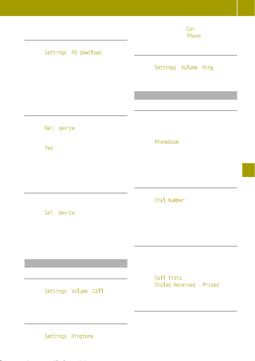
Loading and updating the telephone
book
X
Press the à button.
X
Select Settings > PB download.
X
If necessary, accept the access confirmation on the mobile phone.
If the mobile phone supports the Bluetooth
PBAP (Phone Book Access Profile) profile, the
phone book and call lists will be transferred
after you connect.
Removing a mobile phone from the list
(de-authorizing)
X
Press the à button.
X
Select Del. device.
Authorized mobile phones are displayed.
X
Select the mobile phone to be removed.
X
Select Yes.
®
After de-authorization, the Bluetooth
nection to the mobile phone is no longer
established automatically.
con-
Using a mobile phone
X
To switch on: select Car.
X
To switch off: select Phone.
Adjusting the ring tone volume
X
Press the à button.
X
Select Settings > Volume > Ring.
®
X
Select the setting.
Using the telephone
Calling a contact from the phone book
To call a contact in the telephone book, the
mobile phone telephone book first has to be
imported into the smart Audio-System.
X
Press the à button.
X
Select Phonebook.
X
Select the contact.
The details for the contact are displayed.
X
Dial the desired phone number.
X
Press the 9 button.
93
>> Using the smart Audio-System.
Connecting another authorized mobile
phone
X
Activate Bluetooth®on a mobile phone
X
Press the à button.
X
Select Sel. device.
All authorized mobile phones are displayed. The currently connected mobile
phone is indicated by a dot.
X
Select the desired mobile phone from the
list.
Setting the sound
Adjusting the call volume
X
Press the à button.
X
Select Settings > Volume > Call.
X
Select the setting.
Switching the smart Audio-System ringtone on and off
X
Press the à button.
X
Select Settings > Ringtone.
Dialing a number
X
Press the à button.
X
Select Dial Number.
An input screen appears.
X
Enter the number.
X
Press the 9 button.
X
Select ;.
Using call lists to call contacts
To call a contact in a call list, the mobile
phone telephone book first has to be imported into the smart Audio-System.
X
Press the à button.
X
Select Call lists.
X
Select Dialed, Received or Missed.
X
Select an entry from the list.
Calling the last number dialed
X
Press and hold the à button until the
call is established.
Z

Operating external data carriers
94
Accepting a call
X
Press the à button.
Rejecting a call
X
Press and hold the à button until the
call is rejected.
Holding and continuing a call
X
To place a call on hold: select Â.
X
To continue the call: press the 9 button.
Transferring a call to the mobile phone
X
Select z.
X
To transfer the call back to the smart
Audio-System: press 9.
Entering numbers or characters during a
>> Using the smart Audio-System.
call
X
Select #123.
X
Enter numbers or characters.
Ending a call
X
Press the 9 button.
Using voice control for the mobile
phone
Useful information
The voice control of the connected mobile
phone can be used (see manufacturer's operating instructions). Not all voice control
services are supported by the smart AudioSystem.
Voice control must be activated in the settings menu of the mobile phone.
Starting voice control for the mobile
phone
X
Connect the mobile phone with the smart
Audio-System via Bluetooth
X
Press the button on the steering
®
.
wheel.
A message appears in the display of the
smart Audio-System and a tone sounds.
Voice control for the mobile phone is
active.
X
Speak a voice command.
Ending voice control forthe mobile phone
X
Press the button on the steering
wheel.
or
X
Press the 9 button.
Voice control for the mobile phone is
ended.
Operating external data carriers
Useful information
You can switch between the following media
sources, depending on the type of external
data carrier connected:
R
USB 1 or iPod 1
R
USB 2 or iPod 2
R
AUX (external audio equipment)
R
BT Audio (with Bluetooth®connected
device, such as a mobile phone)
Selecting external data carriers
X
Press the Õ button repeatedly until the
desired media source appears in the display.
Operating a USB device or iPod
®
Connecting a device
X
Connect the device to the USB port.
The device is activated automatically and
the first track is played.

Operating external data carriers
95
Selecting a track
X
In USB mode, press the 9 button.
Available tracks or folders are displayed.
X
Turn control B.
X
Press 9 to confirm.
Rapid search
X
Press the 9 button.
An entry field appears.
X
To enter characters, turn control B and
press the 9 button.
Skipping to the next or previous track
X
Press the D or C button briefly to
skip to the next track or press longer for
rapid scrolling.
Switching random track sequence on/off
X
Press the C button.
Switching the repeat function on/off
X
Press the number key.
Selecting a track from a category with an
®
connected
iPod
X
Press the 9 button.
X
Select the category from a list.
Different categories, such as playlists,
artists or albums, can be selected, depending on the connected device.
Adjusting the volume of external audio
equipment
X
Press the ª button.
X
Select Audio.
X
Select AUX In.
X
Select one of the following options for the
volume:
R
Low
R
Medium
R
High
Bluetooth®device operation
Connecting a device
X
Connect a Bluetooth®audio device the
same way you connect a mobile phone with
Bluetooth
®
.
Skipping to the next or previous track
X
Press the D or C button briefly to
skip to the next track or press longer for
rapid scrolling.
Displaying metadata
X
Press the F button repeatedly until the
desired metadata is displayed.
>> Using the smart Audio-System.
Displaying metadata
X
Press the F button repeatedly until the
desired metadata is displayed.
Operating external audio equipment
(AUX)
Connecting a device
X
Connect the device to the AUX jack.
Use the Õ button to access the media on
a connected AUX device.
Z

Operating and setting up the smart Media-System
96
Operating and setting up the smart
Media-System
Operating the smart Media-System
Please note
Some functions are restricted while driving.
Controls
:
>> Using the smart Media-System.
;
=
?
Switches voice control system on
and off, accepts and ends a phone call
W Increases the volume
X Reduces the volume
smart Media-System display
Voice control system
The following functions are possible using
the voice control system of the smart MediaSystem:
R
Enter a destination for navigation.
R
Make a call.
R
Start an application.
Controls on the smart Media-System
Previous station or track and fast rewind
:
Mute
;
Next station or track and fast forward
=
Switches to the home screen
?
A
On/off button Ü and volume control
Touchscreen
B
Ports on the center console
Port for external audio equipment (AUX)
:
USB port
;
SD card slot
=

Operating and setting up the smart Media-System
97
Overview of home screen
Radio station, media track
:
Message memory
;
Status of the mobile phone and field
=
strength of the mobile phone network
Outside temperature
?
Time
A
Map
B
Next navigation maneuver
C
Context menu
D
Distance to the destination and expected
E
arrival time
Favorites menu
F
Main menu
G
Telephone menu, status of the mobile
H
phone and field strength of the mobile
phone network
The home screen can be set to display the
i
energy flow.
Switching the smart Media-System
on/off
The restart can take several minutes.
i
During the restart, the audio volume cannot be adjusted.
Scrolling through a menu or list on the
touchscreen
X
Touch the touchscreen with your finger.
X
Swipe up, down, left or right.
The selection on the display will then move
in the respective direction.
Selecting items on the touchscreen
X
Tap on a menu, an option or an application
with one finger.
The menu, the option or the application is
launched.
Controlling media playback on the
touchscreen
X
Swipe to the left.
The next media item is played or displayed, e.g. the next track or station.
X
Swipe to the right.
Playback is restarted or the previous
media item is played or displayed, e.g. the
previous track.
Media playback can be controlled in the following playback modes:
R
Radio mode
R
Music and audio playback
R
Image playback
R
Video playback
>> Using the smart Media-System.
Switching on automatically
X
Start the engine.
Switching off automatically
X
Switch off the ignition and open the door.
Switching on and off manually
X
Press the Ü button.
To restart
X
Press the Ü button.
The smart Media-System shuts down and
restarts.
Calling up menus
X
Select Menu on the home screen.
Select one of the following submenus:
R
Multimedia
Radio and media playback
R
Navigation
Navigation system
R
Telephone
Mobile phone functions
R
Vehicle
eco score, energy flow and consumption
details
R
Services

Operating and setting up the smart Media-System
98
Apps and TomTom services
R
System
General systems settings
Confirming settings
X
Select Done.
Settings are accepted.
Switching off the display
X
Select home page > W > Switch off
display.
Adjusting the system settings
Adjusting the display
Setting the daytime brightness
X
Select System > Display .
X
Move the Daytime brightness control to
the left or right.
>> Using the smart Media-System.
Setting the nighttime brightness
X
Select System > Display.
X
Move the Nighttime brightness control
to the left or right.
Activating automatic switching between
daytime and nighttime brightness
X
Select System > Display > Automatic day/
night mode.
Displaying night mode constantly
X
Select Force night mode.
Setting the system language
X
Select System > Language.
A list of available languages is displayed.
X
Select the desired language.
The language of the spoken navigation
i
commands can be selected independently
of the system language.
Changing the on-screen keyboard
X
Select System > Keyboards.
X
Select one of the following keyboard layouts:
R
Latin
R
Greek
R
Cyrillic
For the Latin keyboard layout, it is possible
to choose between the ABCD
, QWERTY, AZERTY
and QWERTZ layouts.
Selecting the home screen display
X
Select System > Home page.
A selection of home screen displays
appears.
X
Select the desired display.
Restoring the factory settings
X
Select System > Factory settings.
X
Confirm with Yes.
All settings changed in the system will
return to the default values. All destinations, routes and Favorites will be deleted.
Setting the time manually
X
Select System > Clock > Set time.
X
Change the minutes and hours of the time
shown.
Activating automatic time adjustment
X
Select System > Clock > Set time > Auto‐
matic time adjustment.
Setting the time format
X
Select System > Clock > Time format.
X
Choose one of the following time formats:
R
18:00
R
6:00 PM
R
6:00
Displaying status and information
X
Select System > Status & Information.
X
Select one of the following information
options:
 Loading...