

Page 1
Devices, Inc.
UL approved for US and Canada
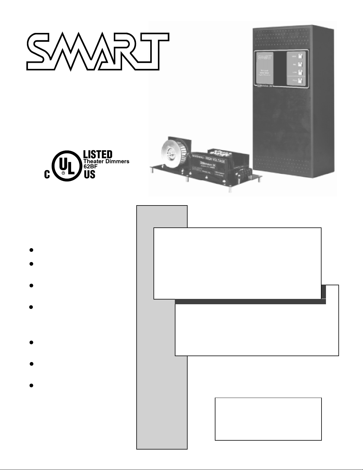
DIMENSION 3K
Three light levels plus a FULL
brightness emergency level.
Low current, ground-to-select
control lines.
A vailable as a open frame unit for
console mounting and as a fully
enclosed wall mount unit. Both
are UL approved.
High current dual SCR for ruggedness and reliability.
Fade defeat for quick and easy
light level adjustment.
Works with low voltage lighting
transformer loads.
THREE STAGE
LIGHT DIMMER
INST ALLA TION AND
OPERA TION MANUAL
Copyright 1999 by SMART Devices, Inc.
5945 Peachtree Corners East
Norcross, GA 30071-1337
1-800-45-SMART
or
770-449-6698
Page 1
Page 2
DIMension 3K
Devices, Inc.
CONT ACT
SMART can be reached by telephone from 8:00 AM to 5:00 PM Monday - Friday if you have questions or need
technical support regarding this or any other SMART product. The phone number is toll free, 1-800-45-SMAR T
(1-800-457-6278). The FAX number is 1-770-449-6728.
SMART is also available by e-mail at the following addresses:
service@smartdev.com for service questions or tech support
sales@smartdev.com for sales questions
engineering@smartdev.com for tech support
Visit the SMAR T WEB site at
http://www.smartdev.com
for new product information, on-line manuals, the SMART bulletin board,
and other information that may interest you.
LIMITED WARRANTY
SMART products and accessories are warranted against malfunction or failure due to defects in workmanship or
materials for a period of one year from the date of shipment. If a problem occurs during the warranty period, the unit
will be repaired, or replaced at our option, without charge for materials or labor. If air freight is requested by the dealer,
the difference between air and surface charges will be billed to the dealer. This limited warranty does not cover products that have been abused, altered, modified, or oper ated in other than specified conditions. Prior factory appro v al is
required on all returns. Returned equipment or defective parts must be shipped freight prepaid to us by the dealer or
customer. Our limited warranty does not cover damages resulting from accident, misuse or abuse, lack of responsible
care, or failures not attributable to manufacturing defects, except as provided herein. SMART Devices, Inc. makes no
warranties, express or implied, including warranties of mer c hantability or fitness for a particular purpose. RETURN
POLICY: Factory authorization MUST be obtained before returning any product. A 15% restocking charge will be
issued on unused equipment (in original box) that is returned for credit. Credit is issued to the dealers account. The
credit may be used against future purchases and no cash transactions are offered. All returns must be shipped freight
prepaid by the dealer. Equipment returned without a factory RA (Return Authorization) will be refused.
Page 2
Page 3

INSTALLATION AND OPERATION MANUAL
INTRODUCTION
The SMART DIM 3K is a three stage light dimmer for cinema lighting control. The DIM 3K is available as a fully enclosed wall
mount version, with or without manual override pushbuttons, or as a open fr ame unit for mounting in a suitable enclosure
such as a projector console. This dimmer is ruggedly constructed and is designed with the highest quality parts for reliable
operation and long life. The dual SCR output is very conservatively rated, and is capable of far more current then the rated
load current of the dimmer. Adequate heat sinking is provided which results in moderate temperature rise even at full rated
load.
UL CONSIDERATIONS
The open frame version is UL approved for mounting in
a UL approved enclosure. The wall mount v ersion is
also UL approved. The UL approval is applicable ONLY
to those units set up for 120 VAC operation and extends
ONLY to those units which have been clearly marked
with the following listing mark:
INST ALLATION
Mounting
Mount the DIM 3K in a well ventilated location to av oid
overheating. Even though the DIM 3K is conserv atively
rated, excess ambient temperature can add to the
normal temperature rise of the product and can possibly
lead to premature failure. Do not block airflow around
the heatsink area as this will cause excessive temperature rise.
Electrical Connections
The DIM 3K can be run from 120 VAC (UL approved) or
from 240V AC (in those countries that use 240VAC for
lighting). The DIM 3K is normally shipped set up for the
proper voltage for your country. It is only necessary to
change some jumper wires on the circuit board to make
the change from one voltage to another. Please contact
the factory if you need to change the supply voltage.
The DIM 3K has no built in circuit breakers or fuses,
and you MUST supply a circuit breaking device (in the
LINE side) of the proper rating for your load. Remember
that for a continuous load, circuit breakers should be
run at about 80% of their current rating.
To determine your current requirements, divide the total
lighting wattage by the line voltage to get the load
current. This is the current at the rated line voltage.
Since the lights will rarely be run at full line voltage, the
actual current will be less in normal operation.
For example, a 3000 Watt load at 120VAC pulls about
25 Amperes of current. If y ou plan to set the HIGH
lights level to the full line voltage, your circuit breaker
would need to be rated at 30 to 35 Amperes. If you are
going to set the HIGH lights levels to around 100V AC,
then the normal current will be less, and the breaker
could be rated at about 25 Amperes.
Page 3
Page 4

DIMension 3K
The line, neutral and load connections are made to the
terminal strip mounted on the chassis at the end of the
heat sink. Make sure that the wire gauge used is rated
for the load current. Use COPPER conductors ONLY.
Make sure that all connections are tight and secure.
The terminals should be torqued to 20 in.-lbs. T he high
load current can cause
problems if connections
are not properly made.
See the diagram to the
left for the LINE, NEUTRAL, and LOAD
connections.
For the most reliable and
stable operation, it is
highly recommended
that each dimmer be fed
from its own breaker in
the distribution panel,
and that SEPARATE
neutrals be run from each
dimmer all the way back
to the distribution panel.
This will help to minimize the possibility of
EMI from the dimmer
affecting other equipment and also EMI from
other equipment affecting the dimmer operation. Try to keep all the
dimmers on the same
phase and OFF the phase
that is used for the sound
systems for minimum
noise.
Control Circuit Connections
Control wiring is very straightforward and is low voltage
(less than 28 VDC) and low current (less than 50 mA).
Use any type of low voltage hookup wire, but shielded
is recommended for best immunity to possible false
triggering from external interference. Belden 8723
would be a good choice. The HIGH, MID, or LOW
terminal must be momentarily connected to the COM
teminal to select the desired light level. Ususally this is
done by connecting to relays in automation systems.
Alternatively, pushbutton switches could be used for
manual selection of light levels. The relays or switch
contacts must be isolated with no external voltages
applied to them. The application of external voltages to
the dimmer control terminals may r esult in damage to
the dimmer.
The FULL terminal is used to place the dimmer instantly
in the full brightness mode. This is useful for emergency
situations such as a fire alarm. This terminal requires a
latching connection to the COM terminal. As long as the
connection is closed between the FULL and COM
terminals, the lights will stay at full brightness regardless
of the condition of the other terminals.
Adjustment
The dimmer has three light levels which must be adjusted
for each individual theatre. The DIM 3k has a remov able
jumper called FADE which can be easily removed to
make the adjustment process quick and easy. This jumper
is located close to the three trimpots which are used to set
the light levels. When the jumper is removed, the light
level changes instantly as you
adjust the trimpots so you do not
have to w ait and w ait for the light
level to stabilize each time you
turn the trimpot. When y ou are
finished making the adjustments
for each of the three light levels,
replace the jumper so that light
level changes are smooth and
gradual for normal operation.
Light Level Adjustment Trimpots
Fade Jumper
OPERA TION
There are no usual oper ation requirements since in most
cinemas, the dimmers are comtrolled by the automation
system. The only operator accesible controls are the
manual override pushbuttons on the wall mount unit. If
the installer has installed some other type of manual
control, please refer to the instructions given by the
installer or cinema manager on the proper operation.
Usually the only time that requires operator intervention
is if the automation system has failed and the booth is
being run manually. Pressing the appropriate pushbutton
will select the desired light level.
Page 4
 Loading...