

Page 1
Advanced, Patented Circle
Surround System with 5
channel capability for future
formats
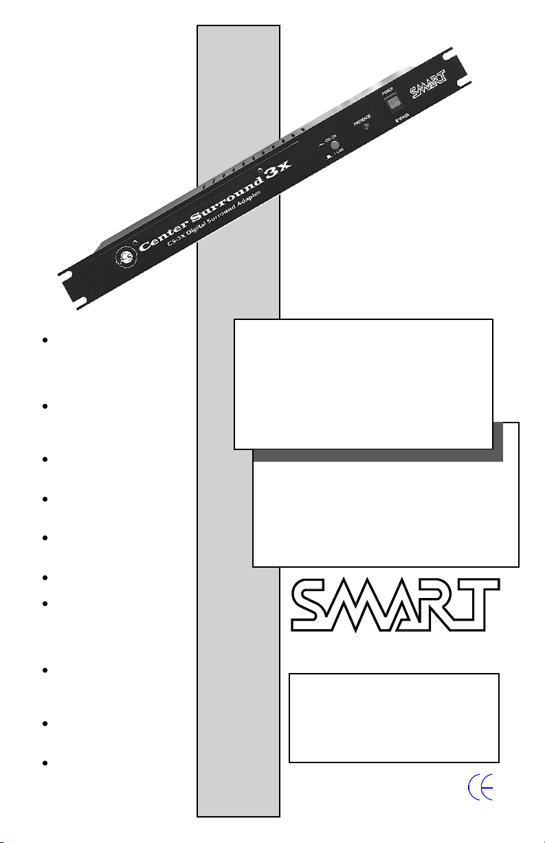
CENTER SURROUND 3X
MULTI-CHANNEL
Full Octave EQ on Left Wall,
Rear Wall and Right Wall
Channels
EQ and Level controls
accessible from front panel
Front Panel Security Cover to
discourage tampering
Presence LED indicates Rear
channel signal
Built-in Bypass System
Works with all brands of
digital players and with
processors that have digital
players attached
One rack unit height - Easily
replaces a vent panel in
crowded racks
DB25 interface for optional
external 1/3 octave equalizer
Easy interface to processor
automation to select digital
or optical formats
SURROUND PROCESSOR
INSTALLATION AND
OPERATION MANUAL
Devices, Inc.
Copyright 2000 by SMART Devices, Inc.
5945 Peachtree Corners East
Norcross, GA 30071-1337
1-800-45-SMART
or
770-449-6698
CS-3X MANUAL REV C.P65
Published 01/18/2000
Page 2
CENTER SURROUND 3X
WARNING: If you do not make the proper connections to the format terminals, the CS-3X will
NOT go into the proper format for digital
soundtracks, and you will NOT get the full benefit of the product.
See the automation hookup section on Page 7.
Page 2
Page 3

Contents
CONTACT.....4
LIMITED WARRANTY.....4
INTRODUCTION.....5
CONCEPTS.....6
INSTALLATION.....7
WIRING.....7
OUTPUT MODES.....7
AUTOMATION HOOKUP.....7
SETUP.....8
EQ and Level Trimpot Section of Front Panel.....8
Control Section of Front Panel.....8
INSTALLATION AND OPERATION
Rear view of chassis showing connections for Mode One Output.....9
Rear view of chassis showing connections for Mode Two Output.....9
OPERATION.....10
VOLTAGE SELECTION AND GROUND LIFT.....11
EXTERNAL EQ.....11
Jumpers W1, W2, W3.....11
Circle Surround is a registered trademark
of SRS Labs, Incorporated, Santa Ana CA
Page 3
Page 4

Copyright 2000 by SMART Devices, Inc.
5945 Peachtree Corners East
Norcross, GA 30071-1337
CONTACT
SMART can be reached by telephone from 8:00 AM to 5:00 PM Monday -
Friday if you have questions or need technical support regarding this or any
other SMART product. The toll free number is 1-800-45-SMART
The FAX number is 1-770-449-6728
SMART is also available by e-mail at the following addresses:
service@smartdev.com for service questions or tech support
sales@smartdev.com for sales questions
engineering@smartdev.com for tech support
Visit the SMART WEB site at
http://www.smartdev.com
for new product information, on-line manuals, the SMART bulletin board,
and other information that may interest you.
LIMITED WARRANTY
SMART products and accessories are warranted against malfunction or failure due to defects in
workmanship or materials for a period of one year from the date of shipment. If a problem occurs
during the warranty period, the unit will be repaired, or replaced at our option, without charge for
materials or labor. If air freight is requested by the dealer, the difference between air and surface
charges will be billed to the dealer. This limited warranty does not cover products that have been
abused, altered, modified, or operated in other than specified conditions. Prior factory approval
is required on all returns. Returned equipment or defective parts must be shipped freight prepaid
to us by the dealer or customer. Our limited warranty does not cover damages resulting from
accident, misuse or abuse, lack of responsible care, or failures not attributable to manufacturing
defects, except as provided herein. SMART Devices, Inc. makes no warranties, express or implied, including warranties of merchantability or fitness for a particular purpose. RETURN POLICY:
Factory authorization MUST be obtained before returning any product. A 15% restocking charge
will be issued on unused equipment (in original box) that is returned for credit. Credit is issued to
the dealers account. The credit may be used against future purchases and no cash transactions are
offered. All returns must be shipped freight prepaid by the dealer. Equipment returned without a
factory RA (Return thorization) will be refused.
Page 4
Page 5

CENTER SURROUND 3X
OPERATION AND INSTALLATION MANUAL
INTRODUCTION
The SMART Center Surround 3X processor enhances the presentation of Digital
Soundtracks by providing Left Rear and Right Rear Surround channels in addition to
the normal Left Wall Surround and Right Wall Surround channels. This effect is available with ALL digital releases and is greatly magnified with the Digital Soundtracks
which have been mixed to take advantage of the additional Rear Wall Surround channel. In addition, separate SP1 and SP2 channels are available which can be used for
future improvements such as Overhead Surround channels or Offstage channels.
The CS-3X processor uses the patented Circle Surround matrix that provides very high
separation between the Left, Center, and Right surround channels. Another similar product uses the older home matrix decoder chip that has a “center pile-up” effect if not
receiving specific encoded material. For this reason the CS-3X will work with any digital soundtrack that has a phantom center channel without center channel “wandering.”
The CS-3X samples the center phantom signal and drives a signal “Presence” lamp on
the front panel of the product that tells the operator that mid surround information is
present.
Full octave band equalization is included to tune the speaker/room combination for
the Left Wall, Rear Wall, and Right Wall Surround channels. Input and Ouput level
trimpots are provided to match levels between normal operating modes and Bypass. A
Rear Surround channel PRESENCE LED on the front panel indicates when Rear Surround channel material is present.
A Bypass mode allows the Left Surround and Right Surround channels to feed straight
through while at the same time mixing into the Rear Wall Surround channel outputs.
Automatic format switching circuitry connects to the format terminals on your stereo
processor.
The Center Surround 3X is a one rack space product that connects between the stereo
processor surround outputs and the surround power amplifier inputs. One or two additional channels of amplification will be needed for the Rear Wall Surround speakers,
and the surround speakers may have to be rewired to create an array of Rear Wall
Surround speakers. See the INSTALLATION section for details.
Page 5
Page 6

CENTER SURROUND 3X
CONCEPTS
Digital Audio tracks are discrete, that is, each track
can contain information that is totally separate from
the information on other tracks. Since they are discrete tracks, it is possible to apply a matrix encoding process to any two of these tracks, just as it is
done for optical stereo prints. Therefore, multiple
channels of audio can be encoded into the two selected tracks. The Digital Left Surround and Digital
Right Surround tracks have been selected to receive
the matrix encoded signals. The new digital prints
have an additional surround channel encoded into
the Left Surround and Right Surround tracks. While
This concept can be extended even further because
the matrix can decode additional channels from
the original two channels. For example, speakers
could be placed overhead so that passover effects
Off Stage Speakers
Right Wall Speakers
Left Wall Speakers
Rear Wall Speakers
digital recording is a fine storage media, at some
point the digital signals have to be converted back
to analog to be heard. A properly designed matrix
is not going to significantly affect the quality of the
resulting analog signals.
The Center Surround 3X processor is a multi-channel matrix decoder that extracts the multiple channels from the Digital Left Surround and Digital Right
Surround tracks and sends these signals on to the
appropriate power amplifiers and speakers. By separating the surround speakers on the back wall of
the cinema into a separate group, these speakers
can deliver sounds from the rear wall channel which
are separate from the left wall and right wall channels.
Overhead Speakers
Left Wall Speakers
Rear Wall Speakers
become much more realistic. These additional channels would have to be encoded on the soundtracks.
The overhead speakers, if used, do not have to be
as high a quality as the surround speakers. In fact,
if the overhead speakers high frequency response
is limited in comparison to the stage and surround
speakers, then the perception will be that the speakers are located higher up than they really are since
high frequencies are normally attenuated more and
more as the distance increases. This gives the illusion of distance which can contribute to the overhead effect.
Alternatively, mid-size full range off-stage effects
speakers could be placed on the side walls, angled
into the audience, between the screen and the surrounds so that voices or effects could be placed
offstage. This all leads to a greater sense of reality
in the audio presentation. These off-stage channels
would have to be encoded on the soundtracks.
Right Wall Speakers
Page 6
Page 7

INSTALLATION
Find an appropriate place in the rack to mount the
CS-3X. A good place is between the stereo processor and the power amps since the wiring will follow this path. Since the CS-3X is only one rack space
high, often you can just use it to replace a vent or
blank panel. This may be important if space is at a
premium. If you are retrofitting an existing installation, you must also provide a place in the sound
rack to mount another power amplifier for the required additional amplification channel(s) for the
rear surround speakers. Depending on the existing
setup, you may already have an additional amplification channel(s) available which can possibly be
used for the new channel(s).
There are no particular ventilation requirements
other than what is typical for other low level processing equipment. However, as always, it is a good
idea to keep ALL electronic equipment running cool
for best reliability and longest life.
INSTALLATION AND OPERATION
Mode One requires a jumper wire be placed on
terminals marked CRW1 and CRW2. Mode two
requires the CRW1 and CRW2 terminals have NO
jumper on them. The factory default is MODE TWO.
Mode Two requires that the rear wall speakers be
wired as two separate channels. This mode needs
two channels of amplification. This is the more expensive method of adding the rear wall channels to
a system because it requires two channels of amplification instead of one. However, you may need
to add a dual channel amplifier anyway if you do
not have a spare amplifier channel. If this is the
case, then use Mode Two. In LS-RS format or BYPASS, the Left Surround signal appears in the Left
Wall speakers AND in the left rear wall speakers.
The Right Surround signal appears in the Right Wall
speakers AND in the right rear wall speakers. This
mode more accurately maintains the channel separation when the system is not in 3X format.
WIRING
If you are placing this unit into an existing installation, the left surround and right surround wiring from
the stereo processor to the power amps must be
removed. Wire the left surround and right surround
outputs from the stereo processor to the left surround and right surround inputs of the CS-3X. Wire
the Left Wall, Right Wall, and Rear Wall outputs of
the CS-3X to the appropriate power amplifier inputs. Use standard wiring practices for low level
audio circuits.
OUTPUT MODES
The CS-3X can be used in one of two output modes.
In the 3X format, there is no difference regardless
of the ouput mode used. The difference appears only
in the normal LS-RS format or in BYPASS.
Mode One requires that all rear wall speakers be
wired as one channel and needs only one channel
of amplification. This is the less expensive method
of adding the rear channel to a system. In LS-RS
format or BYPASS, the Left Surround signal appears
in the Left Wall speakers AND in all the rear wall
speakers. The Right Surround signal appears in the
Right Wall speakers AND in all the rear wall speakers. This gives a partial wrap around effect to the
individual Left and Right Surround sounds and does
not maintain the channel separation as accurately
as Mode Two.
AUTOMATION HOOKUP
Wire the format terminals to the similar format terminals on your stereo processor. This will allow the
automation to control the format switching. The
format terminals have internal protection diodes to
allow systems with pullup voltages higher than
+5VDC to be safely connected to the CS-3X processor.
See the hookup diagrams on Page 9 for wiring information.
CAUTION: When connecting the CS-3X to a Dolby
CP500, the CAT 684 board must be Rev 1 or higher.
Rev E or lower must be changed. Also, the CP500
must have software version 1.51 or higher installed.
WARNING: If you do not make the
proper connections to the format
terminals, the CS-3X will NOT go
into the proper format for digital
soundtracks, and you will NOT get
the full benefit of the product.
Page 7
Page 8

CENTER SURROUND 3X
SETUP
Adjusting the CS-3X is a straightforward procedure.
It consists of setting levels and adjusting equalization. A Real Time Analyzer is required to do EQ. A
Sound Pressure Level meter is required to set levels. Remove the security cover from the front of the
CS-3X to gain access to the EQ and Level trimpots
and LED Indicators.
PLEASE NOTE: The Optical Processor Surround
Equalizers will NOT be used. These Surround Equal-
izers MUST be set to a flat response to avoid frequency and phase errors which will degrade the
performance of the CS-3X. If possible, use the line
inputs on the RTA to look at the surround outputs of
the stereo processor and adjust the surround equalizers for the flattest possible response. Do NOT use
x curve compensation if that option is available on
the RTA. When using a PANASTEREO processor,
simply set the Surround EQ bypass switches to the
BYPASS position. The equalizers in the CS-3X will
be used for the surround channels.
This setup procedure uses 85dB SPL as the level on
which all adjustments are based. If you use a different SPL, make the appropriate compensations
in the example levels shown in the procedure.
Place the CS-3X POWER/BYPASS switch in the
BYPASS position and select LS-RS mode (pushbutton out).
Turn the Rear Wall Amp volume controls all the
way down.
With the pink noise feeding the Left Surround and
Right Surround channels, adjust the LS and RS IN
LEVEL trimpots until the LS CAL and RS CAL LEDs
are just beginning to come on. This sets the proper
level feeding the input of the Circle Surround matrix circuitry.
Turn on only the left surround pink noise.
Adjust the LS equalizers on the CS-3X for proper
frequency response on the Real Time Analyzer. After proper EQ has been obtained, set the L WALL
OUT LEVEL trimpot for 2dB less SPL reading (e.g.,
83dB) than you obtained earlier when adjusting the
Optical Processor Surround output levels. Turn the
Left Rear Wall Amp volume control up to obtain a
2 dB increase in SPL (e.g., 85dB)
Turn on only the right surround pink noise.
Adjust the RS equalizers on the CS-3X for proper
frequency response on the Real Time Analyzer. After proper EQ has been obtained, set the R WALL
OUT LEVEL trimpot for 2dB less SPL reading (e.g.,
83dB) than you obtained earlier when adjusting the
Optical Processor Surround output levels. Turn the
Right Rear Wall Amp volume control up to obtain a
2 dB increase in SPL (e.g., 85dB)
Turn OFF the Left Wall/Right Wall power amp.
Don’t
adjust the volume controls.
Select the CS-3X mode (pushbutton in).
Turn Left Wall/Right Wall Amp volume controls up
to normal (usually 1/2 to 2/3 up).
Adjust the Optical Processor levels to your normal
levels (e.g., 85dB). The Left Surround and Right Surround levels should match the stage levels (e.g.,
85dB on each surround channel).
Place the CS-3X POWER/BYPASS switch in the
POWER position and select LS-RS mode (pushbutton out). Set all CS-3X OUT LEVEL trimpots to mid
position to start.
EQ and Level Trimpot Section of Front Panel
Control Section of Front Panel
Page 8
Turn on the left surround and right surround pink
noise.
Adjust the Rear equalizers on the CS-3X for proper
frequency response on the Real Time Analyzer. After proper EQ has been obtained, set the REAR LEVEL trimpot for 2 dB less SPL reading (e.g., 83dB)
than you obtained earlier when adjusting the Optical Processor Surround output levels .
Turn ON all surround channels power amps.
Page 9

INSTALLATION AND OPERATION
Rear view of chassis showing connections for Mode Two Output
Wire the format terminals to the format
Left Wall Speakers
Right Wall Speakers
terminals on the Stereo Processor
Outputs
Amplifier
Inputs
These inputs are
connected to the
Optical Stereo
Processor Left
Surround and Right
Surround ouputs.
Left Rear Speakers
Right Rear Speakers
Outputs
Amplifier
Inputs
Rear view of chassis showing connections for Mode One Output
Wire the format terminals to the format
Left Wall Speakers
Right Wall Speakers
terminals on the Stereo Processor
Outputs
Amplifier
Inputs
These inputs are
connected to the
Optical Stereo
Processor Left
Surround and Right
Surround ouputs.
Rear Wall Speakers
Outputs
Amplifier
Inputs
Page 9
Page 10

CENTER SURROUND 3X
OPERATION
The CS-3X is automatic in its operation and
requires virtually no operator intervention.
Since the CS-3X format terminals are connected to the Optical Processor format terminals, all switching is done automatically.
There is a pushbutton which can be used to
defeat the CS-3X operation if needed and force
the unit into normal LS-RS operation. This will
not need to be done except in rare instances
where for some reason the digital soundtrack
does not decode well.
It is important to leave the CS-3X/LS-RS
pushbutton in the CS-3X position (in) at all
times unless there is a need to defeat the 3X
mode for some reason such as that mentioned
in the above paragraph. If the pushbutton is
put in the LS-RS position (out), and then
pushed back in, the 3X mode will NOT be reselected until the automation, digital player,
or optical processor has once again selected
the digital format.
If there is a problem with the CS-3X such as
distortion, noise, a dead channel, or some
other problem, then the operator can simply
press the POWER/BYPASS switch to the BYPASS position. In the BYPASS mode, the Left
Surround and Right Surround signals are fed
straight through relay contacts and on to the
amplifiers. In addition, the Rear Wall channels are fed signals from the Left Surround and
Right Surround Signals.
If the power supply in the CS-3X should fail
completely, the unit will automatically go into
BYPASS mode.
The PRESENCE LED on the front panel alerts
the operator that REAR channel material is
present on the digital soundtrack. When this
LED is on, there is program material going to
the REAR WALL speakers in the auditorium.
Page 10
CS-3X/LS-RS Pushbutton
(normally pushed in)
PRESENCE LED
OPERATOR CONTROLS
POWER/BYPASS Switch
Page 11

EXTERNAL EQ
If finer control over the Surround Channels EQ
is desired, the CS-3X octave band equalizers
can be bypassed, and 1/3 octave external
equalizers , such as the SMART EQ6-1/3, can
be patched in through the DB25 connector.
The DB25 connector is male.
The pinout is as follows:
Left Wall Send Pin 25
Rear Wall Send Pin 23
Right Wall Send Pin 21
Left Wall Return Pin 11
Rear Wall Return Pin 9
Right Wall Return Pin 7
Ground Pins 2, 4, 6, 8, 10,
16, 18, 20, 22, 24
To bypass the internal EQ’s, the top cover must
be removed, and Jumpers W1, W2, and W3
must be changed to Pins 2 and 3. Normally,
these jumpers are on Pins 1 and 2 as shipped
from the factory.
INSTALLATION AND OPERATION
Jumpers W1, W2, W3
VOLTAGE SELECTION AND GROUND LIFT
The CS-3X has soldered-in jumpers for voltage selection and ground lifting. These Zero
Ohm Resistors are located at the right end of
the board.
J1 and J3 should be installed for 110-120 VAC
operation.
J2 only should be installed for 220-240 VAC
operation.
Remove R32 if needed to lift the circuit ground
from the chassis ground/AC ground. This may
be necessary if your system has ground loops
which can cause hum.
Page 11
Page 12

Devices, Inc.
Center Surround EX
Installation and Operation Manual
Page 12
Publication Name CS-3X MANUAL REV C.P65
Published 01/18/2000
 Loading...