

SMA SR
QUAD ROBOT
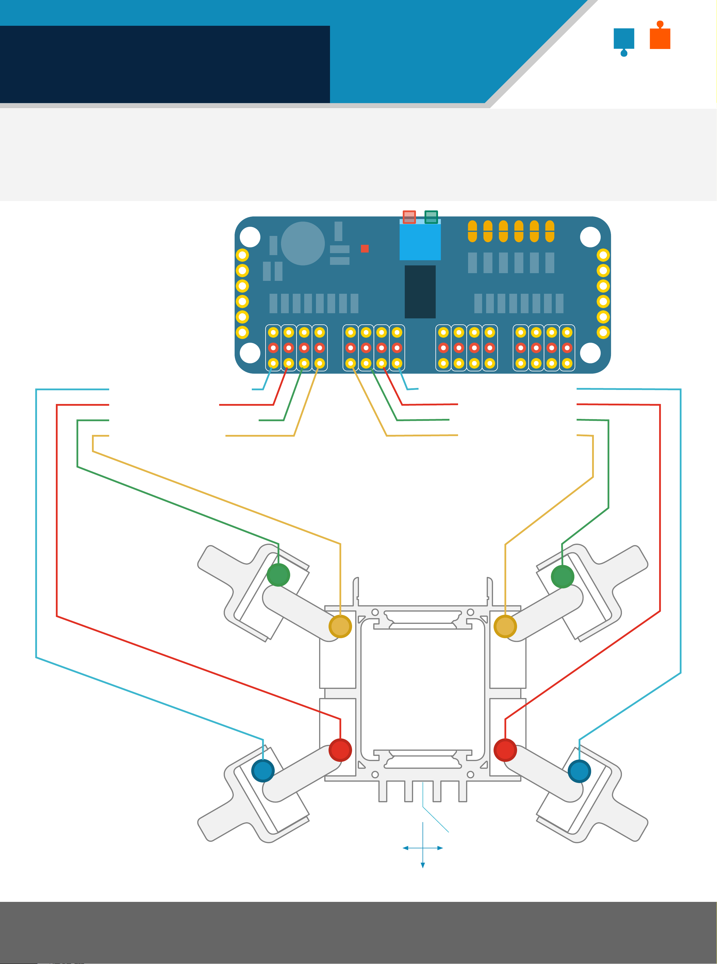
WIRING DIAGRAM
Connect the Servos to the servo driver board using the corresponding port numnbers as shown below.
Servo 1 Top Left Foot
Servo 2 Top Left
GND
OE
SCL
SDA
VCC
V+
POWER
PCA9685
16x12-bit PWM
0 1
2 3
4 5 6 7 8 9 10 11 12 13 14 15
V+
PWM
GND
GND
A5 A4 A3 A2 A1 A0+RW
I2C Address
(Open=0/Closed=1)
V+
Servo 5 Back Right Foot
Servo 6 Top Right
GND
OE
SCL
SDA
VCC
V+
Servo 3 Back Left Foot
Servo 4 Back Left
2
Servo 7 Back Right
Servo 8 Top Right
5
0
3
1
4
6
7
Base
FRONT
SMARS - the Screwless Modular Assembleable Robotic System.
To download the files visit https://www.thingiverse.com/thing:2755973
1
SMA SR
QUAD ROBOT
PRINT PARTS
The following instructions show how to assemble the SMARS Quad Robot. A bill of materials is provided at
the back of this guide along with links to where to buy the components from. Links to the 3d printed
parts are also provided at the back of this guide.
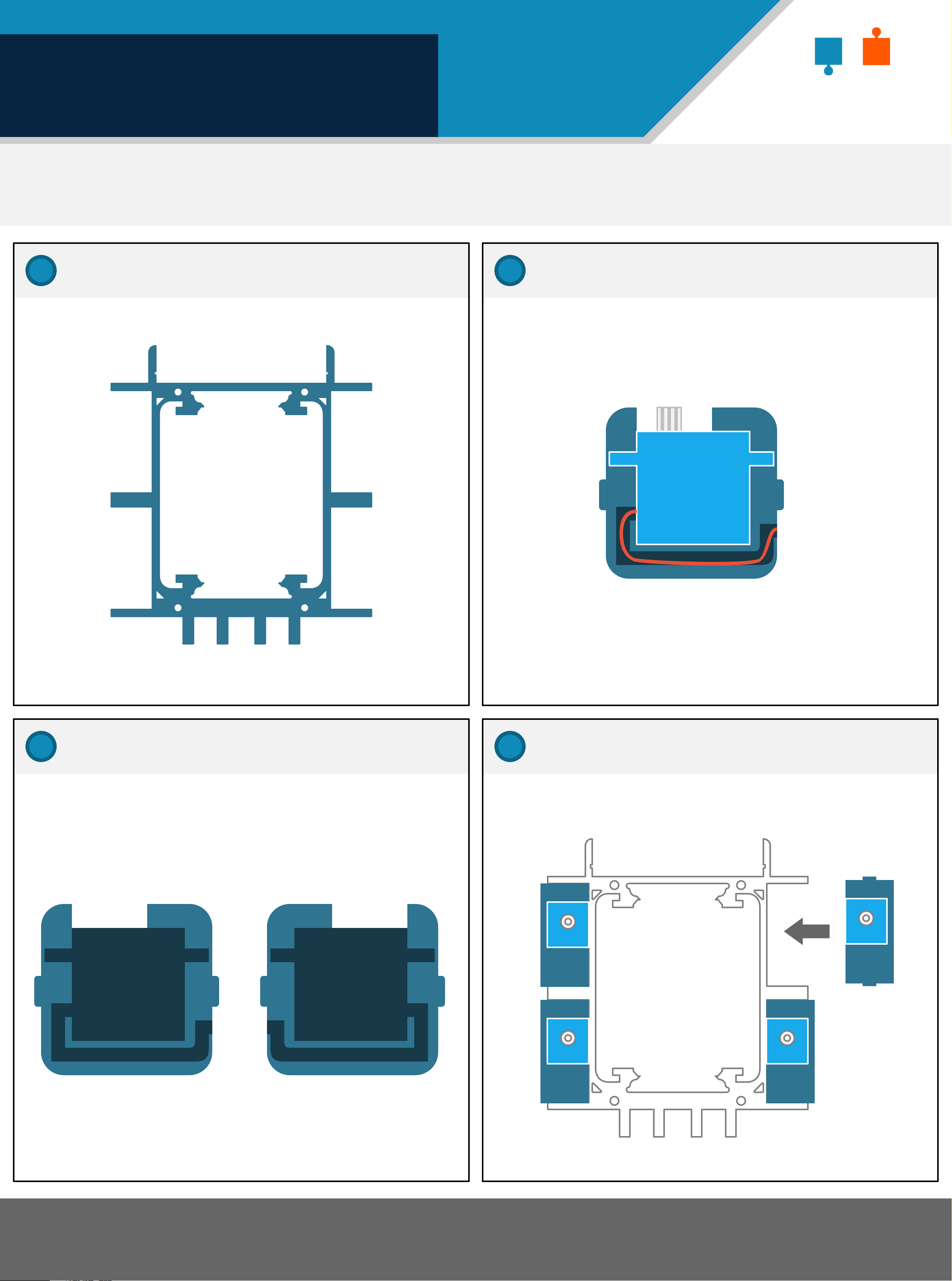
1
Print the frame
3
Fit the servo into the servo holder
SG90
Servo
x8
2
Print 4x Servo holder & 4x Servo holder M (M is
a mirror image of the servo holder)
Print the servo holders
4
Fit the servo holders into the frame
Servo Holder Servo Holder M
SMARS - the Screwless Modular Assembleable Robotic System.
To download the files visit https://www.thingiverse.com/thing:2755973
2
QUAD ROBOT
FITTING SERVOS
SMA SR
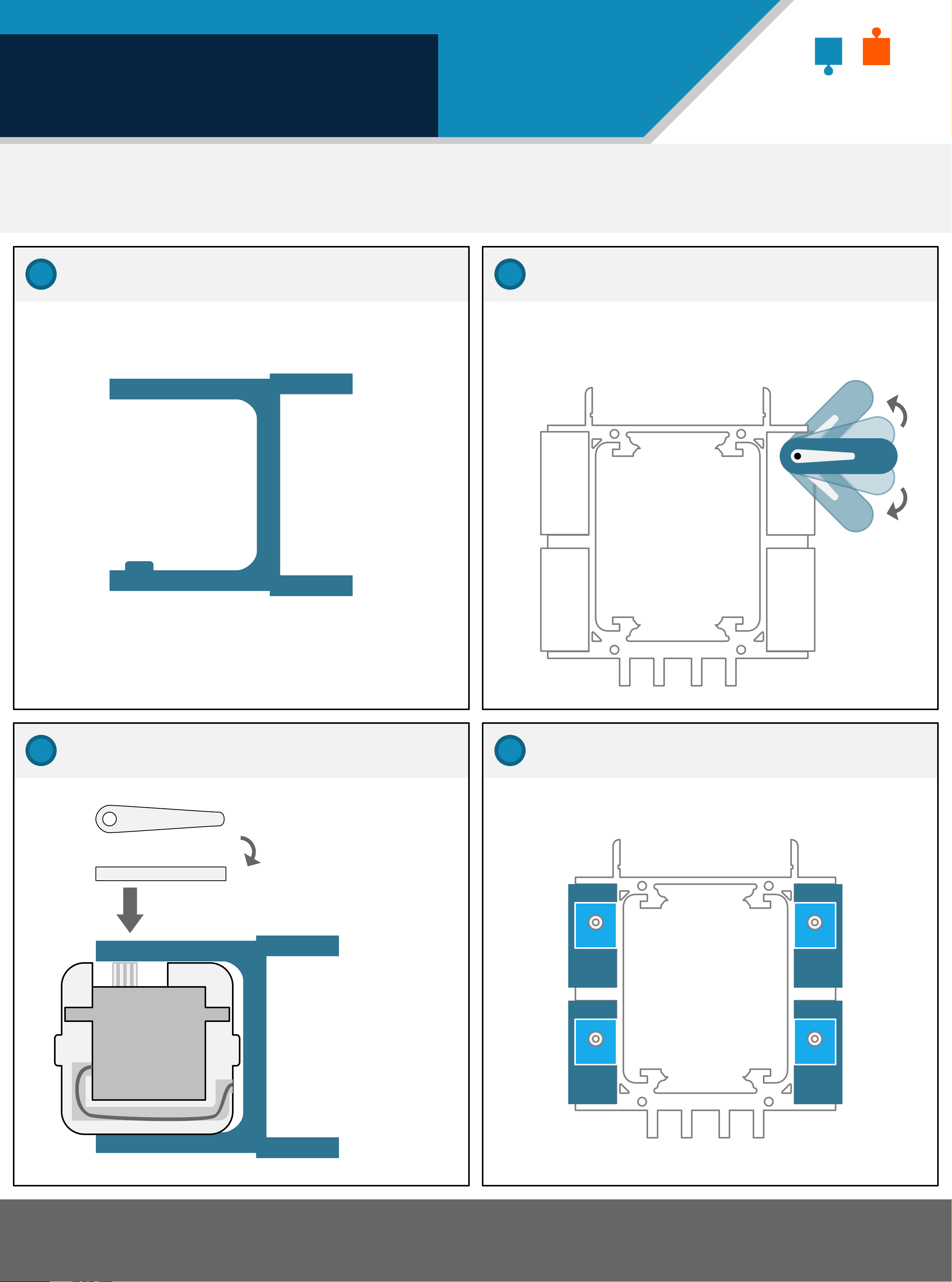
5
Print the servo arms
7
Ensure the servo can move equally in each
direction before tightening the screw.
Check the servo rotation
6
x4
Mount the servo holder in the servo arm
Insert the servo
horn onto the
8
Attach the other servo holders to the frame
SG90
Servo
servo and screw
in securely to
the servo arm
SMARS - the Screwless Modular Assembleable Robotic System.
To download the files visit https://www.thingiverse.com/thing:2755973
3

QUAD ROBOT
FITTING THE FEET
SMA SR
9
Print the feet x4
11
Check the servo rotation
170
160
150
140
130
120
110
100
180
Feet need a rotation
of between 50º to 150º
degrees
x4
90
80
70
60
50
40
30
20
10
0
10
Mount the foot on the servo holder
12
Download the python code
From the raspberry pi command line type:
git clone https://www.github.com/kevinmcaleer/smars
Then look in the folder at the python files.
cd smars
ls smars
x4
SMARS - the Screwless Modular Assembleable Robotic System.
To download the files visit https://www.thingiverse.com/thing:2755973
4

QUAD ROBOT
PI ZERO SETUP
Connect the Raspberry pi Zero using the following pins:
PCA9685 GND to RPI Pin 39 (or Pin 6) - Black wire
PCA9685 V+ to RPI Pin 2 - Red wire
PCA9685 SCL to RPI Pin 5 (SCL) - Green wire
PCA9685 SDA to RPI Pin 3 (SDA) - Blue wire
SMA SR
Note that the input voltage for the PCA9685 is 3.3v or 5v into the VCC. The V+ is for powering the
servo motors and requires more power than the raspberry pi can provide, which is why it is separate.
You can use a 9v battery to drive this, using the SMARS 9v case.
The raspberry pi communicates with the servo driver board using I2C, which only requires 2 wires:
System Clock (SCL) and System Data (SDA). These are marked on servo driver board, and on pins 3 & 7
on the Raspberry Pi Zero.
GND
OE
SCL
SDA
VCC
V+
POWER
PCA9685
16x12-bit PWM
0 1
2 3
4 5 6 7 8 9 10 11 12 13 14 15
V+
PWM
GND
V+
GND
A5 A4 A3 A2 A1 A0+RW
I2C Address
(Open=0/Closed=1)
GND
OE
SCL
SDA
VCC
V+
BCM 19 (MISO)
BCM 26
Ground
35
37
39
36
38
40
BCM 13 (PWM1)
BCM 6
31
33
32
34
BCM 0 (ID_SD)
Ground
BCM 5
29
30
27
28
25
26
BCM 11 (SCLK)
23
24
BCM 10 (MOSI)
BCM 9 (MISO)
3v3 Power
BCM 27
BCM 22
13
15
17
19
21
16
18
20
22
14
BCM 4 (GPCLK0)
Ground
BCM 17
11
7
9
8
10
12
BCM 2 (SDA)
BCM 3 (SCL)
3v3 Power
1
3
5
2
4
6
Ground
BCM 12 (PWM0)
Ground
BCM 16
BCM 20 (MOSI)
BCM 21 (SCLK)
BCM 1 (ID_SC)
BCM 7 (CD1)
BCM 14 (TXD)
BCM 15 (RXD)
BCM 18 (PWM0)
Ground
BCM 23
BCM 24
Ground
BCM 25
BCM 8 (CE0)
SMARS - the Screwless Modular Assembleable Robotic System.
To download the files visit https://www.thingiverse.com/thing:2755973
5v Power
5v Power
Ground
5

QUAD ROBOT
RANGE OF MOTION
SMA SR
10
0
20
30
40
50
60
70
80
90
100
110
120
130
140
150
160
Each servo has a range of motion
between 0º and 180º degrees. However
the each robot leg only needs between
0 and 90 degrees of rotation.
The servos are oriented differently
for each leg, so the degrees of
rotation for each needs to be
understood and set correctly in the
code.
170
Range of Motion
Front Left = 0 to 90
180
Front Right = 90 to 180
Back Left = 90 to 180
50
40
30
20
10
0
90
Back Right = 0 to 90
100
110
120
130
140
80
90
150
60
160
70
170
180
180
170
160
150
140
130
120
110
100
90
FRONT
0
90
80
70
60
50
40
30
20
10
SMARS - the Screwless Modular Assembleable Robotic System.
To download the files visit https://www.thingiverse.com/thing:2755973
6

QUAD ROBOT
SOFTWARE SETUP
SMA SR
Python environment setup
The PCA9685 servo driver library is provided by
Adafruit and needs to be installed before setup
and using the SMARS Quad robot.
To download the adafruit servo library first
logon to the Raspberry Pi and then type:
sudo apt-get install git build-essential python-dev
cd ~
git clone https://github.com/adafruit/
Adafruit_Python_PCA9685.git
cd Adafruit_Python_PCA9685
sudo python setup.py install
Type ‘1’ to change the current channel.
Select Channel
--------------
currently selected channel is: 0
type channel number:, or q to return to the main menu
Next, type ‘0’ to configure channel 0
Then type ‘q’ to return to the main
Python is now setup for the servo
driver.
Quad Robot Software Configuration
Once you’ve downloaded the python code you can
begin checking the configuration of the servos:
python limb_setup.py
menu.
Menu
----
1) select channel
2) select angle
0) quit
current channel is: 0
current angle is: 0
enter number
Type ‘2’ to set the angle for the
Use the menu to select the channel you
want to configure. There are 16
channels, one for each servo.
The channels start at 0, and end at 15.
Menu
----
1) select channel
2) select angle
0) quit
current channel.
Select Angle
------------
current angle is: 0
Type angle to set servo to, or press q to exit90
90
Angle is: 90
Angle = 90
Angle as a percentage = 50.0
pulse = 375
map Max = 450
current angle: 90
Type angle to set servo to, or press q to exit
current channel is: 0
current angle is: 0
enter number
Type ‘1’ to change the current channel.
Select Channel
--------------
currently selected channel is: 0
type channel number:, or q to return to the main menu
Type ’90’ to set the angle to 90
Degrees.
Then type ‘q’ to return to the main
menu.
Repeat this until you have set each
limb correctly.
Finally type ‘0’ to quit the limb setup
programme.
Next, type 0 to configure channel 0
SMARS - the Screwless Modular Assembleable Robotic System.
To download the files visit https://www.thingiverse.com/thing:2755973
7

QUAD ROBOT
NEXT STEPS
About this Guide
This guide was written by Kevin McAleer and is provided freely to the SMARS community.
Social Media
If you haven’t already, please join the facebook community https://www.facebook.com/groups/141101273276325/
SMA SR
SMARS - the Screwless Modular Assembleable Robotic System.
To download the files visit https://www.thingiverse.com/thing:2755973
8
 Loading...