

Page 1
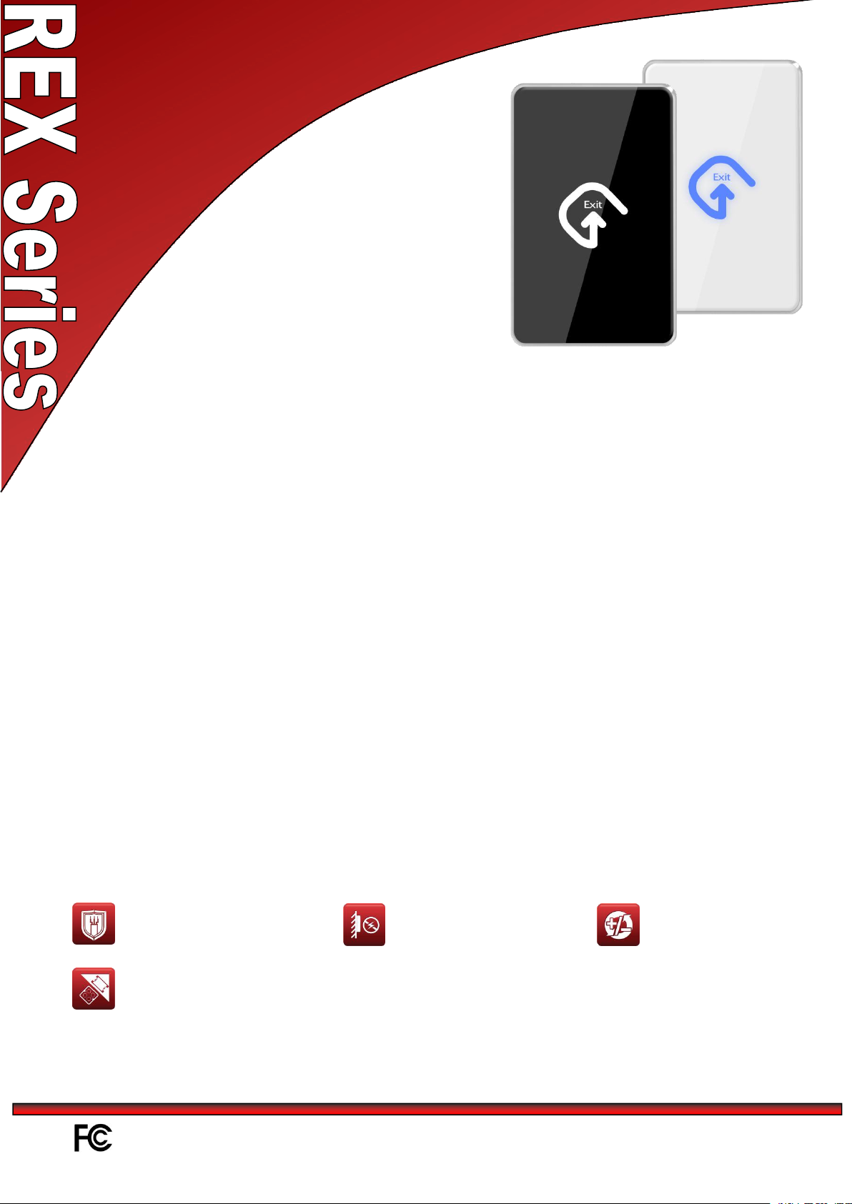
Contactless Door Egress Device (North America Version)
Match OEM reader design in order to maximize the marketing value at the door.
Design Philosophy
Capacitance Proximity Technology has been used instead of Infar-red technology – environmental
independent design.
Back Light design.
Built-in buzzer
When triggered, the back lit will change color with an audible tone – very user friendly.
Provide a dry contact output to interface with any Access Control controller.
Build-in Mechanical Override in case of power failure or electronic failure.
Build-in a digital timer to control the relay output timing from 1 to 63 sec..
Optional with Remote Control (433MHz) to trigger the REX output remotely.
Each Remote Control can “learn” up to 5 Remote Buttons.
Technology & Function
Friendly Installation
All input and output signals are
protected against static
charges.
Reverse power protection.
All inputs are 12Vdc protected.
Fit with US single gang box
Page 2
Specification:
Model
Functions
REX2140-c
Functional Specification
Request to Exit
indication
Color changes from Blue to Green with a beep
Request to Exit output
Dry contact output
REX Relay
NC/NO jumper selectable rated @ 30Vdc; 1A
Mechanical Override
Available
Output Timer
From 1 sec to 63 sec
Remote Button
(Optional)
433MHz
(Max supports 5 remote buttons at the same time.)
Dimension
118.2 (L) X 74.2 (W) X 8.5 (H) mm (above surface)
Technical Specifications
Typical Read range
~2.5 cm
Electric Gang Box
Requirement
Shall fit with most of the North America single gang box installation
Weight
157g
Operating Voltage
10 - 15VDC
Case material
PC+ABS
Operating Current
150mA (max @ 12Vdc)
Standard Color
Black & White
Operating Temperature
0℃-60℃
Operating Humidity
10% - 90%
Operating Specification:
Page 3

FCC Caution.
§ 15.19 Labelling requirements.
This device complies with part 15 of the FCC Rules. Operation is subject to the
following two conditions: (1) This device may not cause harmful interference, and (2)
this device must accept any interference received, including interference that may
cause undesired operation.
§ 15.21 Information to user.
Any Changes or modifications not expressly approved by the party responsible for
compliance could void the user's authority to operate the equipment.
§ 15.105 Information to the user.
Note: This equipment has been tested and found to comply with the limits for a Class
B digital device, pursuant to part 15 of the FCC Rules. These limits are designed to
provide reasonable protection against harmful interference in a residential installation.
This equipment generates uses and can radiate radio frequency energy and, if not
installed and used in accordance with the instructions, may cause harmful interference
to radio communications. However, there is no guarantee that interference will not
occur in a particular installation. If this equipment does cause harmful interference to
radio or television reception, which can be determined by turning the equipment off
and on, the user is encouraged to try to correct the interference by one or more of the
following measures:
-Reorient or relocate the receiving antenna.
-Increase the separation between the equipment and receiver.
-Connect the equipment into an outlet on a circuit different from that to which the
receiver is connected.
-Consult the dealer or an experienced radio/TV technician for help.
Page 4

FT Function switch
RC Function switch
For door open duration setting
from 1 to 63 seconds.
REX2 (US Gang Box version) is a contactless proximity exit button. It is using capacitive proximity
technology instead of Infra-Red to realize the contactless triggering. While Infra-Red technology exit
button will trigger by sunlight, air conditioner or even a paper…etc, capacitive proximity technology
does not have such problems. This makes REX2 a very ideal product for applications which requires
a high hygiene requirement standard.
Function:
Put your hand near the exit button then you will trigger the device. The color of the exit button
will change to green when triggered. At the same time, the relay inside the exit button device will
trigger for 1 second, and the buzzer will beep once.
To adjust the door open duration, please power off the exit button. Change the DIP Switch setting
to alter the door open duration from 1 to 63 seconds, and then power it up again.
Support manually door open
Support remote controlled door open
PCB setting description:
Version 1.0 15JUN2016
REX2-c Installation and Operation Manual
Page 5

Wiring
1
ON
1
No.1,2,4,8,16,32 are used for adjusting door open duration
ON = valid
OFF =invalid
Door open duration=To add all the ON position switch numbers
Example:
If we set #1 and #8 to “ON”, the door open during will be:
1+0+0+8+0+0=9, the decimal number is 9 seconds ( decimal number)
*Setting all DIP Switch to OFF position means door open duration=1sec.
OFF
0
2
ON 2 OFF
0
4
ON 4 OFF
0
8
ON 8 OFF
0
16
ON
16
OFF
0
32
ON
32
OFF
0
RC
ON
RC ON
In certain installation environments, when the device’s maximum
capacitive value is reached, setting RC to the ON position can reset the
baseline of measured capacitive by offsetting a pre-programmed value to
return it to a normalized triggering status.
OFF
RC OFF
FT
ON
FT ON
When FT is set to the ON position. a higher triggering threshold value
will be adopted to prevent false trigger
OFF
FT OFF
Label
Description
+12V
Power Input (+12VDC)
RTE_COM
Exit Button Output (Dry Contact)
RTE_NO
RTE_NC
MO
Manual Open Input,Active Low
GND
Signal Ground (0 VDC)
Fig.1
Fig.4
Fig.3
Fig.2
M-type Buckles
DIP Switch Setting:
Installation:
1) Confirm if the size of installation box fits
for the REX2 as shown in Fig.1
2) Confirm all wirings are in the correct
position, then set the jumpers to the right
position
3) Put the whole module into the installation
box and fixed by screw as Fig.2.
4) There are 2 M-type buckles at the bottom of
the cover as shown in Fig.3. Buckle them
into the slot at the bottom of the module and
push the upper part of the cover up as Fig.4
Version 1.0 15JUN2016
Page 6

baseline value
Setting RC to the ON position can adjust the
baseline value downward to return it to a
normalized triggering status
Setting FT to the ON position can adjust
the triggering threshold value upward to
prevent false trigger
Normal triggering waveform
FT OFF triggering threshold value
FT ON triggering threshold value
baseline value
Version 1.0 15JUN2016
 Loading...