

Page 1
Keypad & Proximity Flash Mount Reader Installation Manual
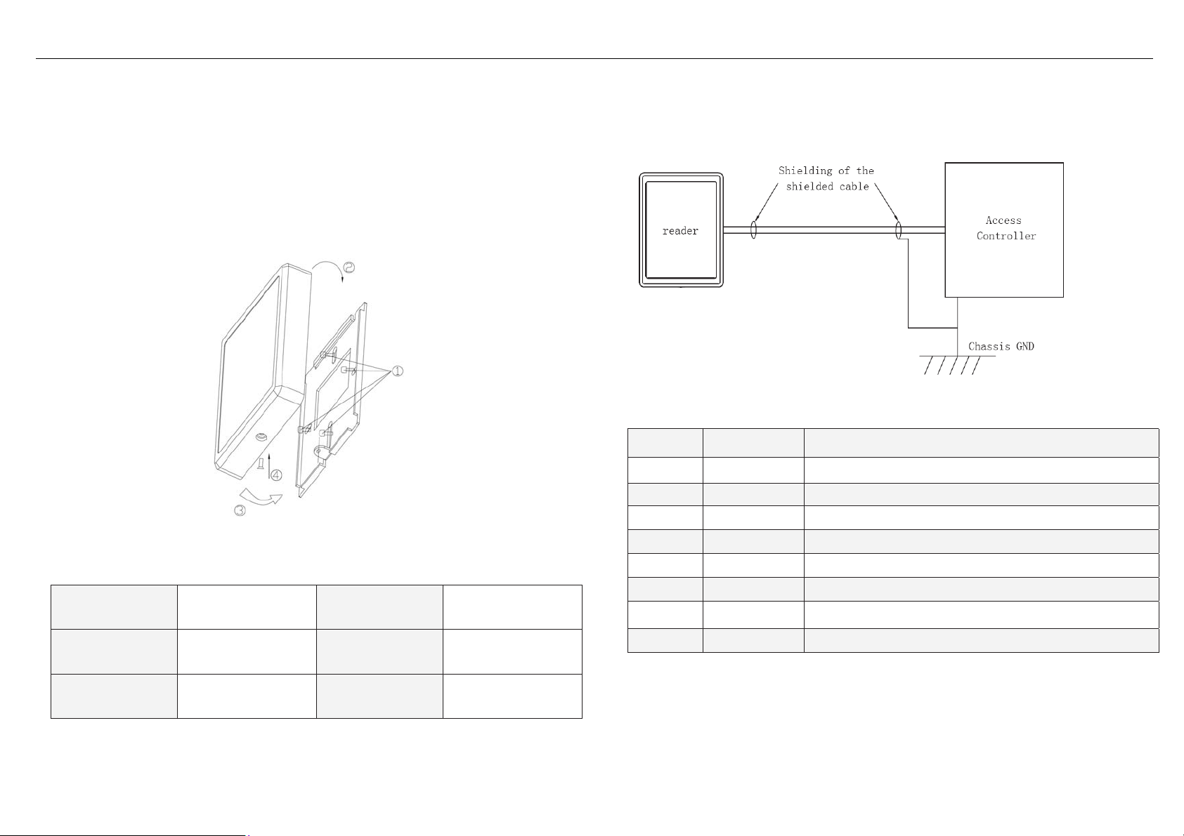
Mounting:
1. Install the metal plate on the wall with two or four screws, which depends on different kinds of
gang box being installed
2. The cover shall clip on the upper edge
diagram
3. Tighten the secure non-dropout screw, which located underneath of the reader to fix the
reader and the back plate
3.
1.
2 the push in the bottom part as show in
4, installation is completed.
Recommendation:
1. Linear DC Power Supply;
2. 22AWG shielded cable; it’s required to do “one-point” ground. (As shown in the diagram)
Color Label Description
Red
+12V dc
Power Supply to the reader
Specification:
Input Voltage (at
Reader end)
Operating Current
Operating
Temperature
Power up Sequences:
DC10V~15V
160mA (max)
-30ºC~70 ºC
Typical Read
range
Maximum Cable
Length
Number pad
format
4 bits burst by default
> 5cm
150m
Black GND Signal GND
Green
White
Yellow
Blue
Brown
Orange
Data0
Data1
RED LED
Green LED
Buzzer
Tamper
Wiegand Output data, D0
Wiegand Output data, D1
RED LED control, active low.
Green LED control, active low
Buzzer input, active low
Tamper output (open collector, Active low, max 100mA)
Wiring:
1. When reader is powered up, the Green back will flicker for 5 seconds. The reader will beep
Page 2

Keypad & Proximity Flash Mount Reader Installation Manual
once and the reader is in Ready mode.
2. Present the card. The Blue LED will flicker once; buzzer will beep once.
3. When card is present and read by the reader, blue back lit will flash once; and buzzer will
beep once as well. The card data will then transmit to the controller. After, weather the back lit
of the reader will remain ON or Flash or change to Green or Red c olor, this shall depend on
the Green and Red LED inputs.
4. For number pad reader, when a number is pressed and successfully detected, the back lit
under the number will flash 1 time and the buzzer will beep once. The number being pressed
will burst out by default (4 bits burst).
Physical Dimension:
Troubleshooting:
Trouble List Solution
No Response
when Power Up
Auto Restart
Cannot read card
number correctly
Reader beeps but
No card data info
Buzzer error z Check if the buzzer cable is correctly connected (See “Wiring” above).
Back Lit Error
z Discount the power and confirm that the power supply cable is
correctly connected (See “Wiring” above).
z Check the input voltage is sufficient (See “Specifications” above).
z Check the input voltage is sufficient (See “Specifications” above).
z Check the format setting on the controller if it is the same as the card
format. Use approved card (known format and Facility Code) to test.
z Check if the shield cable is correctly connected to Classis Ground at
ONE point only.
z Check if data 0 & data 1 cable is correctly connected (See “Wiring”
above).
z Check the input voltage at the card reader end is correct (See
“Specifications” above).
z Check the Led cable is correctly connected (See “Wiring” above).
z Use Default Configuration Card to set it back to normal.
 Loading...