

Page 1
SC101 Core Shoulder
Service Manual
Page 2

Content
CH1 Serial Number Location 1
CH2 Safety Instruction 2
CH3 Preventive Maintenance 4
CH4 Specification and Assembly Guide 8
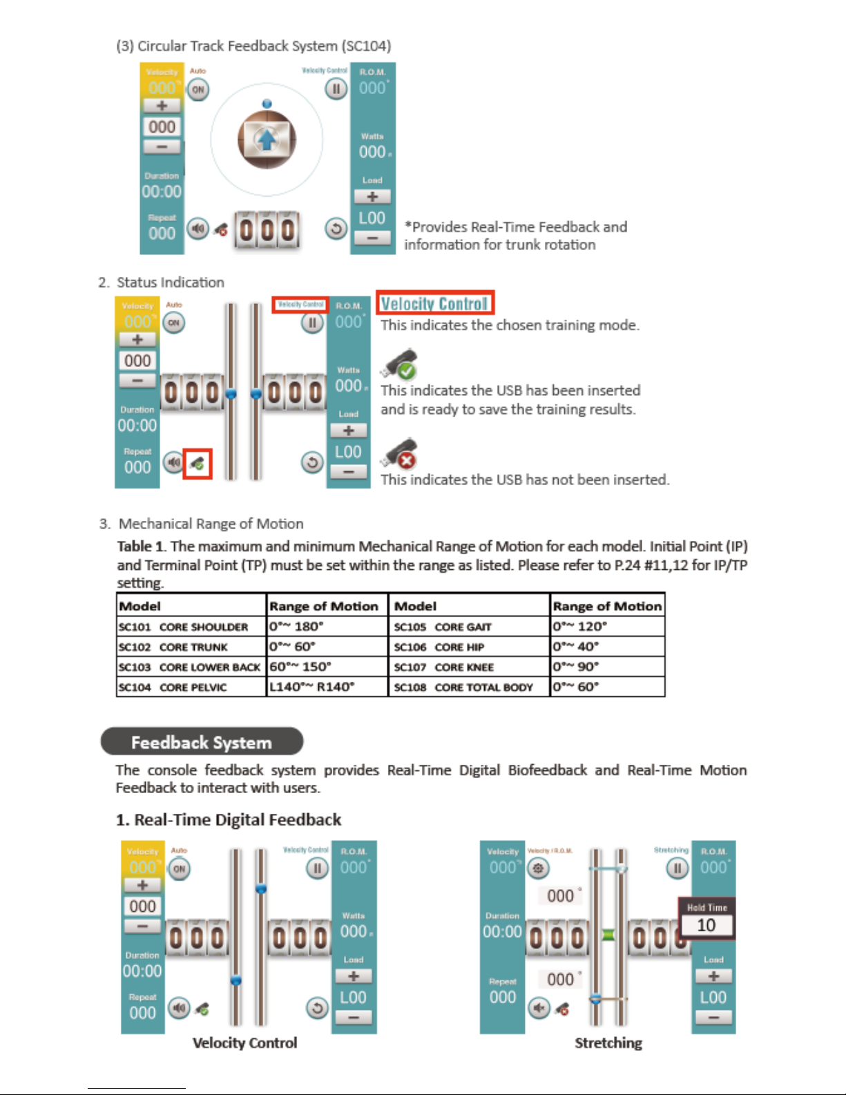
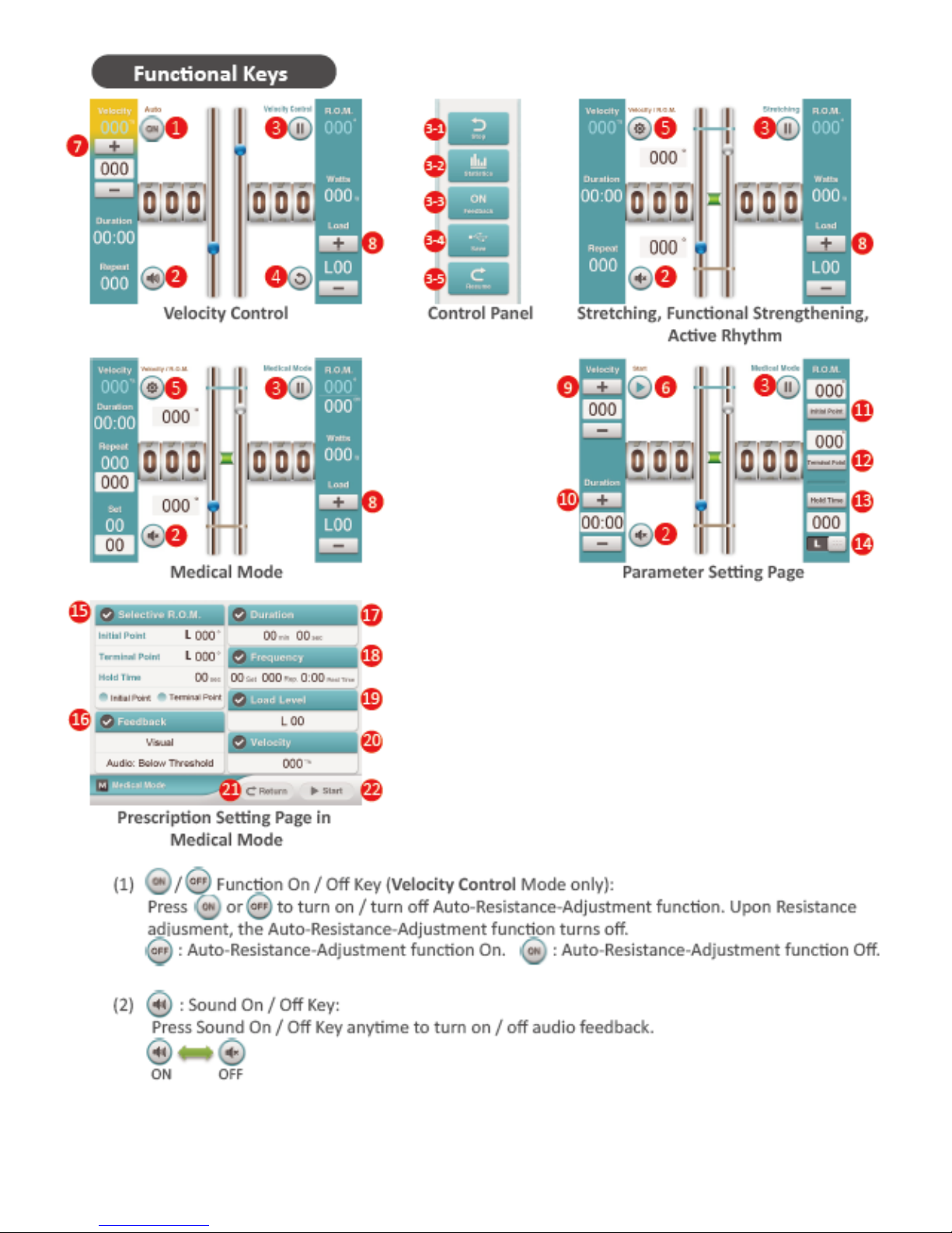
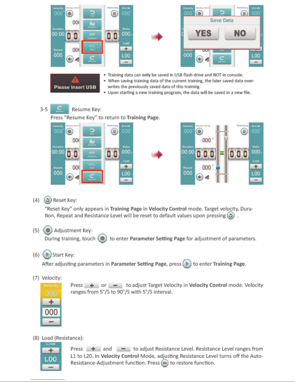
CH5 Console and Program Description 10
CH6 Engineer Mode 23
CH7 Troubleshooting 28
CH8 Parts Replacement 36
Page 3

CH1 Serial Number Location
1
Page 4

Thank you for choosing SMARC products!
It is the owner’s responsibility to ensure that all users are fully informed of all warnings and precautions.
Please read this manual thoroughly before operating SMARC products. If you have any question
after reading this manual, please contact customer tech support at the local authorized dealers or
visit www.twpmhc.com for more details.
SAFETY
GENERAL SAFETY
1. Be cautious when getting on and off equipment seats to avoid falling.
2. Always set up all safety devices and pull the armrests down before exercising. For users with poor
control of trunk and limbs, make sure the seat is in locked position.
3. To prevent injuries, follow the instructions below:
• Never place hands close to the seat base when rotating the seat.
• Never place hands between the narrow spaces of the equipment or reach into the range of
motion limiters (eg. SC101, SC103, SC105, SC107 and SC108).
• Keep clear of the range of motion handles when the equipment is occupied.
• Be careful when operating the equipment to avoid tripping over equipment frames
(Stretching Tube of SC103 ).
• Do not sit on or lean against the armrests.
• If unusual situation has been observed (noises, no console display, loosen parts, and etc),
stop operation and contact local distributors immediately.
• Do not place the equipment outdoors or in area with high humidity.
4. Products are for continuous operation, and are not intended to be used in oxygen rich environment
nor to be sterilized. Do not perform servicing and maintenance while ME equipment is in
use.
ELECTRONIC SAFETY
1. This equipment must be grounded. If the equipment should malfunction or breakdown, grounding
provides a path to reduce the risk of electrical shock.
2. Please unplug the power cord wire to shut down the power.
3. Improper connection of the grounding conductor can result in risks of electric shock. Do NOT modify
the plug provided with the equipment. If it does not fit the outlet, have a proper outlet installed by a
qualified electrician.
4. Pulling on the cord can cause damage to the power cord. You should always pull on the actual plug.
5. With energy conservation in mind, the console will automatically go dark when SMARC product has
not been used for 30 minutes. Main Page will reappear when the equipment is used again.
6. WARNING: To avoid the risk of electric shock, the equipment must only be connected to supply
mains with protective earth.
7. SMARC products forms a ME SYSTEM when connected to a power supply, and can be operated at a
voltage of 115V or 230 V.
8. Do not position the ME Equipment that makes it difficult to disconnect the device (eg. to unplug).
9. The USB socket on SMARC console should ONLY be connected with USB flash drive provided by
PMHC and authorized dealer. It should ONLY be used with the purpose of exercise data download
and prescription upload. SMARC products are not suitable for connecting with any other electrical
equipment. Connecting with other devices might cause potential electromagnetic interference.
CH2 Safety Instruction
2
Page 5

PRECAUTION
FOR GENERAL CONSUMERS
1. If users experience any kind of discomfort, including chest pain, nausea, dizziness, shortness of
breath, severe joint pain or muscle pain, stop training immediately and consult physician or physical
therapist before continuing.
2. Warm up prior to exercise. Start exercise with light, repetitive, dynamic, site-specific movement.
3. Avoid over-stretching to prevent strain of soft tissues and joint instability.
FOR PATIENTS WITH MEDICAL NEEDS
Patients may operate SMARC products under supervision of physicians or physical therapists.
Users with following medical and therapeutic needs (especially over 40 years old) should consult
physician or physical therapist before operating.
1. Inflammation: Patients with inflammatory neuromuscular disease such as Guillain-Barre disease,
Polymyositis, and Dermatomyositis should use low Resistance training.
2. Severe cardiopulmonary disease: Patients with acute symptoms such as but not restricted to the
following should not attempt Resistance training.
• Coronary artery disease (unstable angina, myocardial infarction)
• Carditis
• Cardiomyopathy
• Aortic stenosis and Aortic dissection
• Decompensated congestive heart failure
• Severe pulmonary embolism
• Unstable hypertension
• Ventricular arrhythmia
3. When a hematoma or other indication of tissue trauma is observed.
4. Musculoskeletal Disorder: Patients who recently had a fracture, and bony union is not completed. A
bony block limits joint motion.
5. Neurological Disorder Patient: Only patients with good static sitting balance or Brunnstrom stage
above III are recommended using SMARC products.
6. Do not set high Resistance for children, elderlies, and patients with osteoporosis.
7. Be aware of medications a patient is using that can alter acute and chronic responses to exercise.
8. The equipment might emit low intensity electromagnetic pulse. Patients with concern should
consult physician or physical therapist before operating.
3
Page 6

1. General Maintenance
1) SMARC products require only the most basic general maintenance, performed on an asneeded basis every 6~8 months.
2) Minimum qualifications of SERVICE PERSONNEL: Only technicians trained by PMHC and
associated distributors are supposed to do maintenance. Please contact PMHC factory or
local authorized dealer for maintenance.
The MANUFACTURER will make available on request circuit diagrams, component part lists, descriptions,
calibration instructions, or other information that will assist SERVICE PERSONNEL to repair those parts
of ME EQUIPMENT that are designated by the MANUFACTURER as repairable by SERVICE PERSONNEL.
2. Recommended Cleaning (optional)
1) With the system turned OFF, wipe down all surfaces with a damp cloth. Neutral detergent
and water can be used to remove stains and scuff marks. Inspect all locking and adjustment
mechanisms for signs of damage.
2) NOTE: DO NOT use cleaning solutions containing ammonia or alcohol to clean. Neutral
detergent and water should be sufficient. Allow the system to dry thoroughly before
resuming operation.
CH3 Preventive Maintenance
4
Page 7

1) Applying grease
Chain Maintenance and Tightness Adjustment
Chain maintenance must be held at least once
ever 6 months, depending on the frequency of
use.
Please apply grease to chain links and sprocket
area as indicated on the left.
5
Page 8

2) Tightness (tension) adjustment
Step1:Loosen the nuts above and beneath the “Turn Buckle”
Step2:Adjust the tightness (tension) of chain via turning the “Turn Buckle”
Chain Maintenance and Tightness Adjustment
Nut
Turn Buckle
6
Page 9
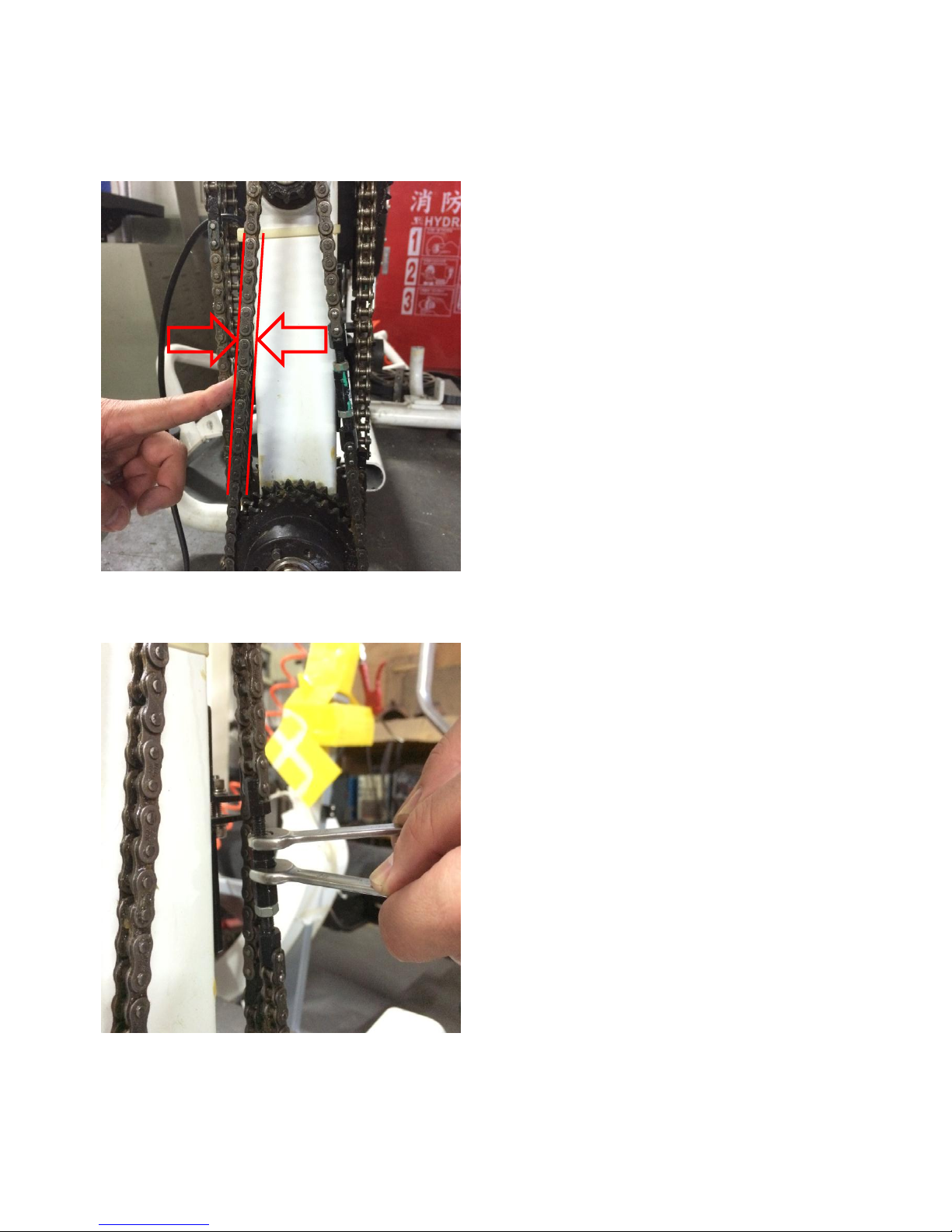
Step3:Check the tightness (tension) by pressing the chain. The standard tightness (tension) is
5~10 mm flexibility when pressed.
Step4:Tighten the nuts
Chain Maintenance and Tightness Adjustment
7
Page 10
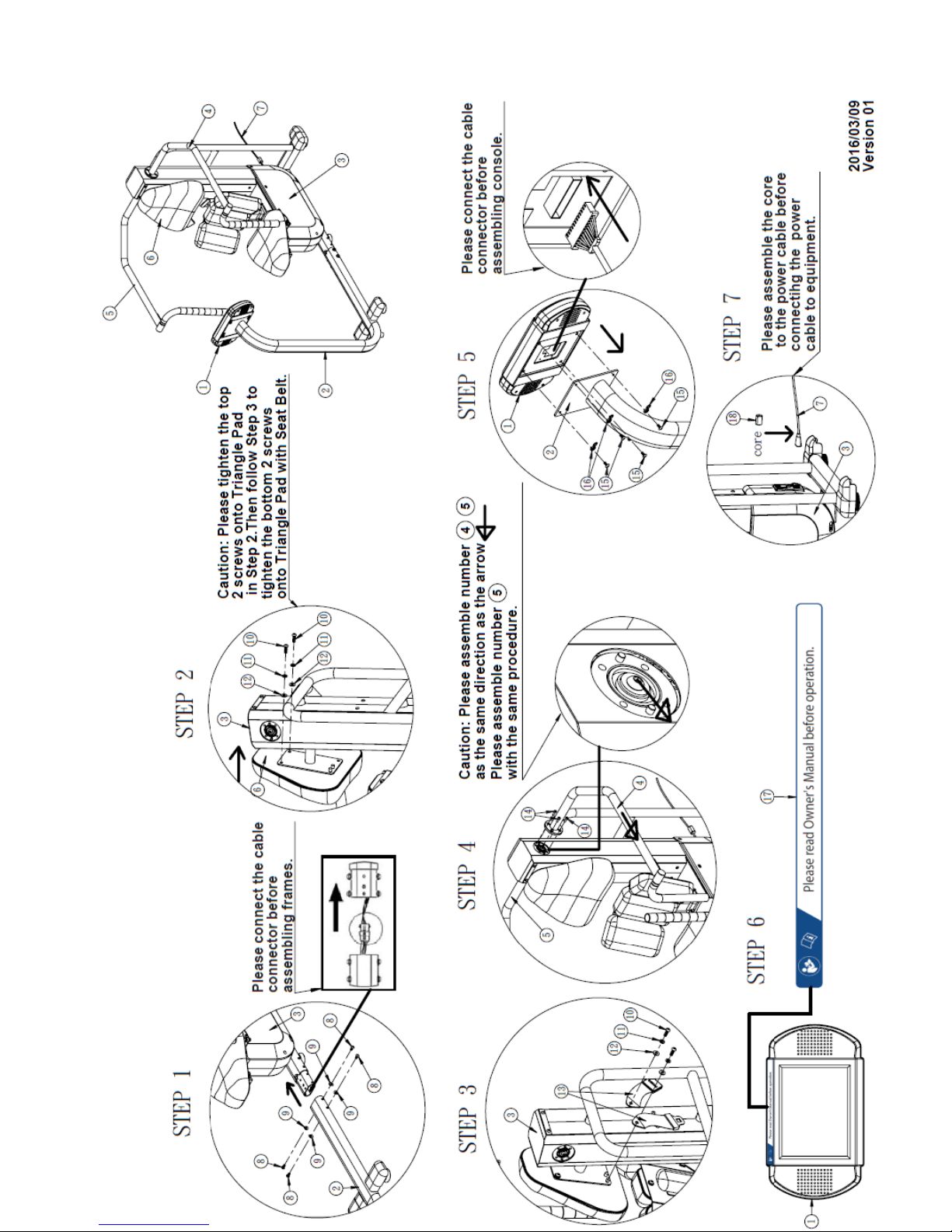
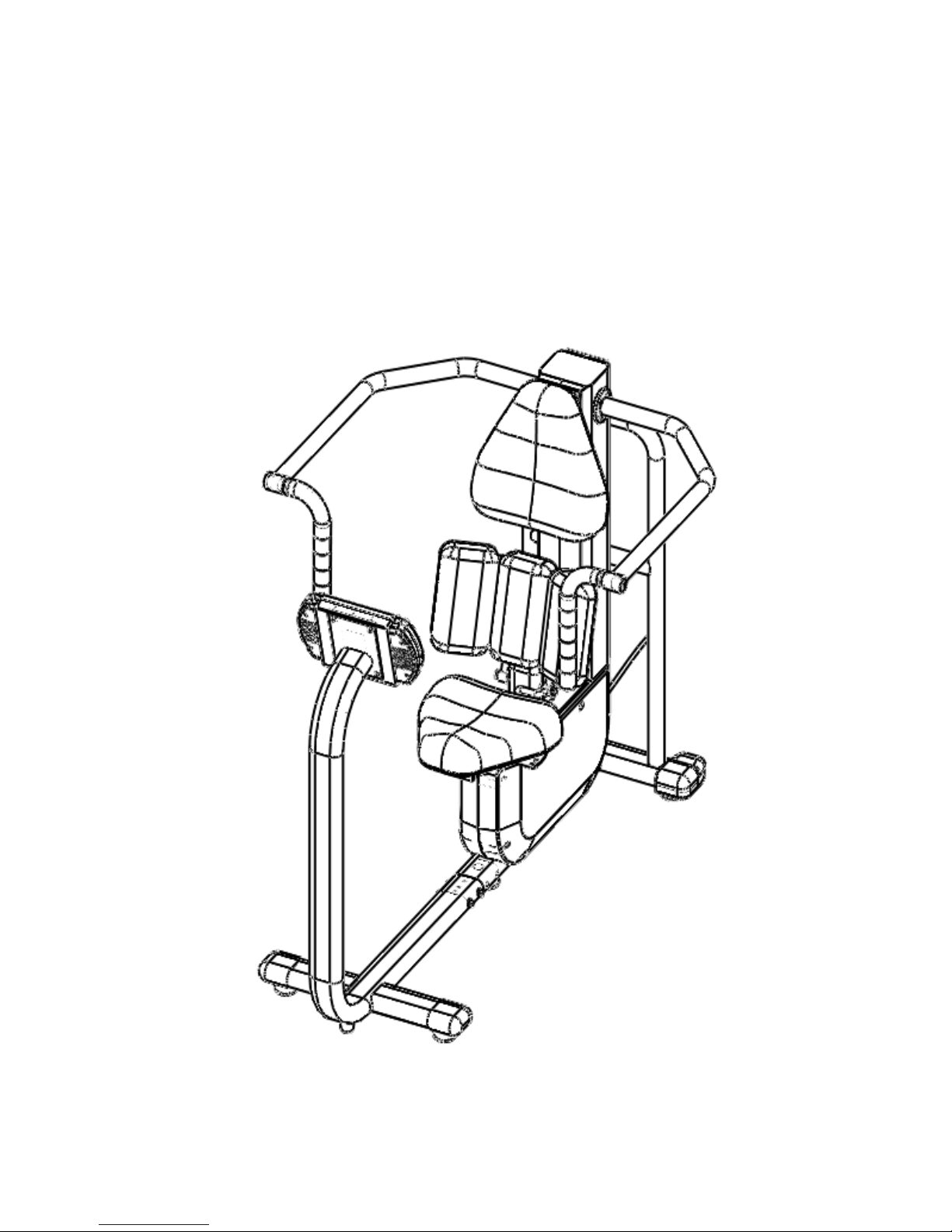
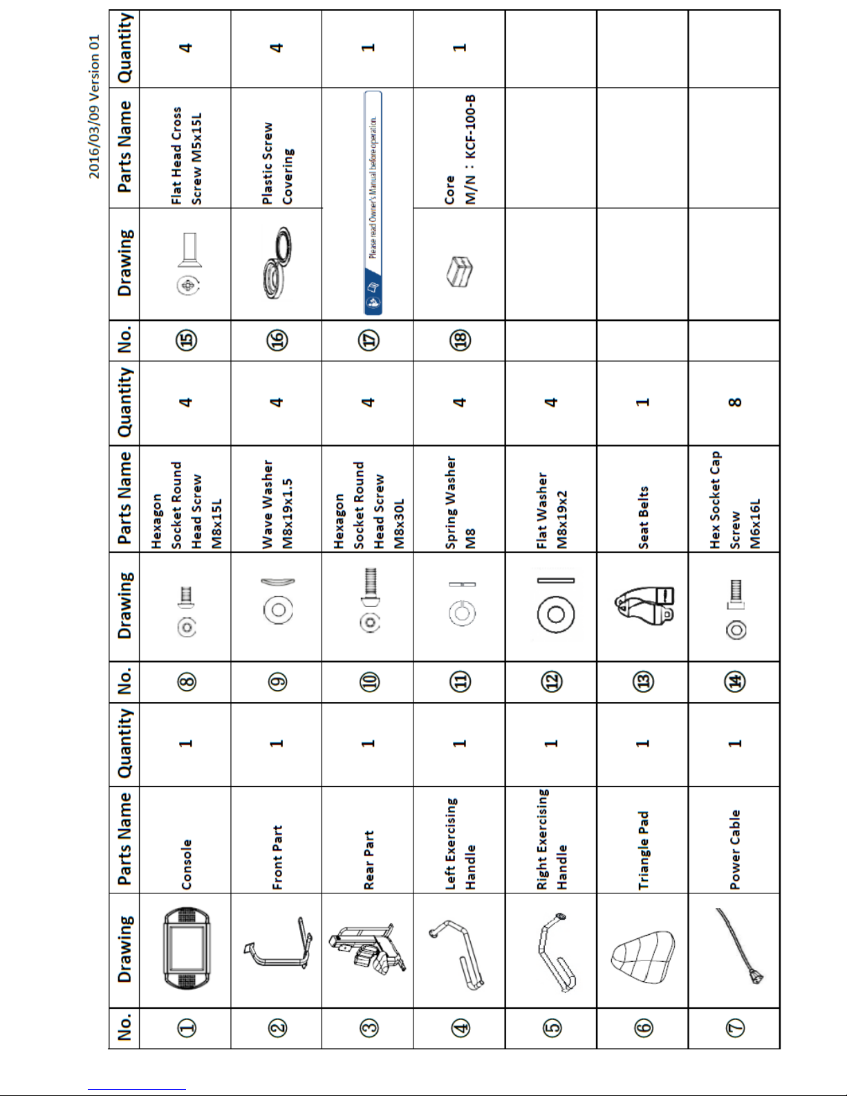
CH4 Specification and Assembly Guide
8
Page 11
9
Page 12

CH5 Console and Program Description
10
Page 13
11
Page 14

12
Page 15
13
Page 16

14
Page 17
15
Page 18

16
Page 19

17
Page 20

18
Page 21

19
Page 22

20
Page 23

21
Page 24

22
Page 25

CH6 Engineer Mode
Model Setting
Mode Setting
23
Page 26

24
Page 27

25
Page 28

26
Page 29

27
Page 30

Lower Control Board Wires Installation
Encoder Wire
Console Wire
Lower Control
Board Power Wire
Generator
Power Cord
CH7 Troubleshooting
28
Page 31

1) No console display when powered on
1.1 Check the “Voltage Switch” if it has been switched to the appropriate
voltage, to 115V or 230V
1.2 Check the fuse if it is functioning
29
Page 32

1.3 Change a new console to eliminate console breakdown
1.4 Check if the Transformer wires and cables are loosened or damaged
1.5 Check the “Lower Control Board Power Wire is still in place
Check if there is power output
Make sure the wires are properly connected (the
power wire is inside the main frame tube)
30
Page 33

1.6 Check if the Console Wire has been properly connected to the
“Lower Control Board”
1.7 Check if the Console Wire has been properly connected to the
Console
31
Page 34

2) Console angle display error
2.1 Check if Console Wire has been properly connected to “Lower Control
Board”
2.2 Check if Encoder Wire has been properly connected to the “Lower
Control Board”
Angle display breakdown or
abnormal angle displayed
during exercise
32
Page 35

2.3 Check if Encoder Wire has been properly connected to the Encoder
2.4 Change Encoder or Encoder Set and see if the problem has been
solved upon changing
33
Page 36
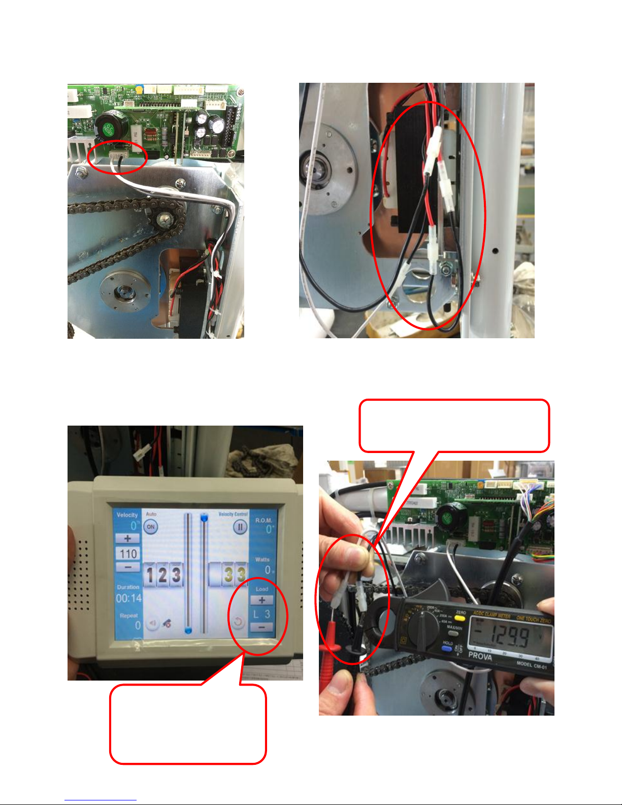
3) Resistance output error
3.1 Check if the Generator Power Cord has been properly connected
3.2 Check if power output is normal
Adjust Resistance
(Load)
Check if there is power
output
34
Page 37

3.3 Change another piece of “Lower Control Board” to see if
the problem has been solved upon changing
3.4 Change another piece of Generator to see if the problem has been
solved upon changing.
35
Page 38

I. Tools list
• Hex wrench x1 Set
• Diagonal pliers x1 pcs
• Needle-nose pliers x1 pcs
• Phillips screwdriver x1 pcs
• 10 mm Open ring wrench x2 pcs
• 13 mm Open ring wrench x2 pcs
• 10 mm Open end torque wrench x1 pcs
• Sprocket position adjustment tool
(replacement with ruler is acceptable) x1 pcs
• 4 mm T hex wrench x1 pcs
• Angle gauge x1 pcs
• Grease (No.2) As needed
• LOCTITE 243 As needed
CH8 Parts Replacement
36
Page 39

II. Cover Removal
1. Steel cover removal
Step 1:Remove Hex Socket Cap Screws and both exercise
handles.
Step 2:Remove Phillips Screws and the Steel Covers (top, right
and left).
37
Page 40

2. Plastic covers removal
Step 1:Remove Phillips screws on both sides of the cover.
Step 2:Remove the Plastic Covers.
38
Page 41

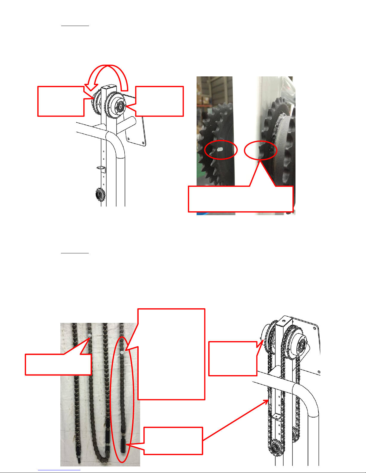
III. Chain Replacement
1.2 Exercise Handle Chain installation
Step 1: Install the Exercise Handle Chain with Turn Buckle facing
to the back of the equipment.
1. Driving Chain replacement
1.1 Driving Chain removal: Loosen the Chain Adjustment Set
(Turn Buckle) to remove the Chain.
Turn Buckle
Turn Buckle
39
Page 42

Step 3: Adjust the chain tightness by adjusting the Turn Buckle.
Apply Loctite 243 to Turn Buckle screw.
Step 2: Place and adjust the chain position. The white colored
labels on both the chain and the sprocket should align.
40
Page 43

2. Replace the Direction Turning Chain
2.1 Remove the Driving Chain:Loosen the Turn Buckle to remove
the Driving Chain.
2.2 Install the Direction Turning Chain
Step 1: There are two white colored labels on the Direction
Turning Chain. Upon installation, these labels should
align with the corresponding white colored labels on
the two sprockets.
41
Page 44
Step 2: Adjust both left and right sprockets where by the
white colored labels are facing towards the back end of
the equipment.
Step 3: Install the Direction Turning Chain, the white colored
label and the label on left sprocket should align, install
entire chain and the second label should also align to
the corresponding label on the right sprocket.
Left
sprocket
Right
sprocket
White colored labels
oriented in this position
Turn Buckle
Head
Left
sprocket
This white
colored label
should align
to the
corresponding
label on the
left sprocket
Second label
42
Page 45

Step 4: Adjust the chain tightness by adjusting the Turn Buckle.
Apply Loctite 243 to Turn Buckle screw.
Step 5: Swing the handles and check if the Turn Buckle
remained a safe distance to the sprocket.
43
Page 46

Step 6: Both handles should be able to position paralleled to
the ground simultaneously.
44
Page 47

IV. Generator and Generator Chain Replacement
1. Generator removal
Step 1: Remove Generator Fixation Screws.
Step 2: Loosen Generator Adjustment Screws, and push the
generator towards the direction of the arrow (as
indicated below).
45
Page 48

Step 3: Remove Chain Lock and remove chain.
Step 4:Remove Generator.
46
Page 49
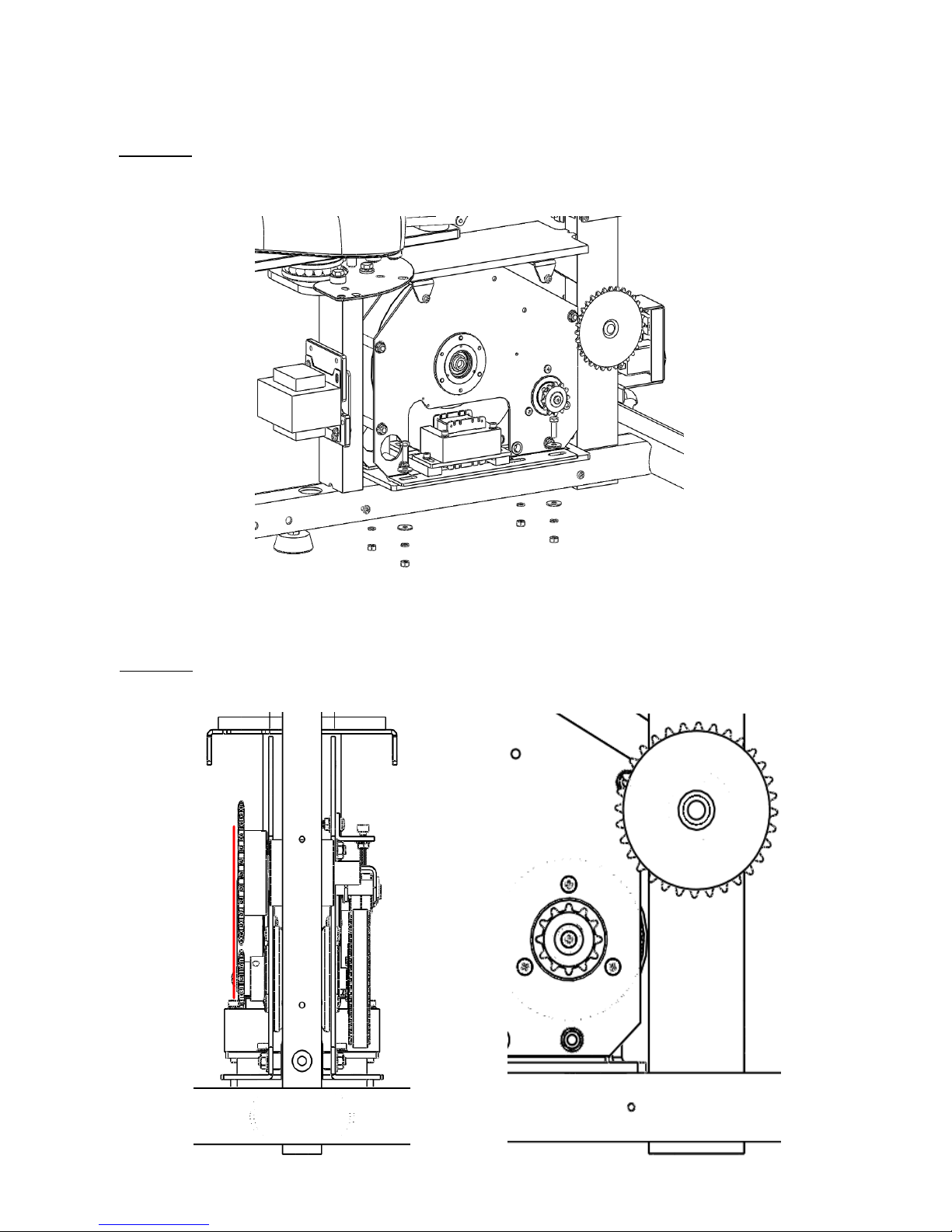
2. Generator and Generator Chain installation
Step 1: Position the Generator on the frame, apply Fixation Screw
to settle the Generator.
Step 2: Ensure the Chain Gear is in parallel with Frame Gear
(can be observed looking sideway).
47
Page 50

Step 3:Install the chain and fix the Chain Lock.
Step 4: Adjust chain tightness by adjusting the Adjustment
Screws.
48
Page 51

Step 5: Fix the Generator with Hex Head Cap Screws, apply torque
force of 150 Kgf/cm to the screws.
49
Page 52

3. Apply Grease to Chain:
Step 1: After replacing the chains, apply grease to the chain
and sprocket keys.
50
Page 53

V. Wires and Parts Diagram
1. Wires and Parts connection diagram
51
Page 54

NO.
Parts Name Quantity
1.
WEE
-0000101-2
Electro
-Magnetic System - Short Axis Version 1
2.
WCM
-0000475-7
Encoder Control Set (A)
1
3.
WEE
-0000139-6
Console Set
1
4.
WEE
-0000140-9
Power Supply Unit
- Long 1
5.
WEE
-0000172-1
Transformer
1
6.
WEE
-0000084-6
Electro
-Magnetic System Cable-L400 1
7.
WEE
-0000156-7
Encoder
Cable-L350 1
8.
WEE
-0000124-5
Console Extension Cable
-L1900 1
9.
WEE
-0000159-8
Power Cord
-L900 1
10.
WEE
-0000006-2
Console Cable
-L1400 1
11.
WEE
-0000055-5
Lower
Control Board 1
3.
2.
11.
1.
4.
5.
2. Parts position
52
 Loading...