


TT303
PROFIBUS PA TEMPERATURE
TRANSMITTER
OPERATION & MAINTENANCE
INSTRUCTIONS MANUAL
TT303
VERSION 3
APR / 15
T T 3 0 3 M E

web: www.smar.com/contactus.asp
www.smar.com
Specifications and information are subject to change without notice.
Up-to-date address information is available on our website.
smar

Introduction
III
INTRODUCTION
The TT303 is from the first generation of Profibus PA devices. It is a transmitter mainly intended for
measurement of temperature using RTDs or thermocouples, but can also accept other sensors with
resistance or mV output such as: pyrometers, load cells, resistance position indicators, etc. The
digital technology used in the TT303 enables a single model to accept several types of sensors, an
easy interface between the field and the control room and several others features that considerably
reduces the installation, operation and maintenance costs.
The digital technology used in the TT303 enables the choice of several types of transfer functions,
an easy interface between the field and the control room and several interesting features that
considerably reduce the installation, operation and maintenance costs.
The TT303 is part of Smar's complete 303 line of Profibus-PA devices.
Some of the advantages of bi-directional digital communications are known from existing smart
transmitter protocols: Higher accuracy, multi-variable access, remote configuration and diagnostics,
and multi-dropping of several devices on a single pair of wires.
The system controls variable sampling, algorithm execution and communication so as to optimize
the usage of the network, not loosing time. Thus, high closed loop performance is achieved.
Using Profibus technology, with its capability to interconnect several devices, very large control
schemes can be constructed. In order too be user friendly the function block concept was
introduced.
The TT303, like the rest of the 303 family, has some Function Blocks built in, like Analog Input.
The need for implementation of Fieldbus in small as well as large systems was considered when
developing the entire 303 line of Profibus-PA devices. They have common features and can
configured locally using a magnetic tool, eliminating the need for a configuration tool or console in
many basic applications.
Now, thanks to Fieldbus, the transmitter accepts two channels, i.e., two measurements. This
reduces the cost per channel. Other function blocks are also available. They allow flexibility in
control strategy implementation.
Get the best result of the TT303 by carefully reading these instructions.
WARNING
In case of using Simatic PDM as the configuration and parameterization tool, Smar recommends that
the user does not apply the option "Download to Device". This function can
improperly configure the field device. Smar recommends that user make the use of the option
"Download to PG / PC" and then selecting the Device Menu, use the menus of the transducer,
function and display blocks acting specifically, according to each menu and method for reading and
writing.

TT303 – Operation and Maintenance Instruction Manual
IV
Waiver of responsibility
The contents of this manual abides by the hardware and software used on the current equipment
version. Eventually there may occur divergencies between this manual and the equipment. The
information from this document are periodically reviewed and the necessary or identified corrections
will be included in the following editions. Suggestions for their improvement are welcome.
Warning
For more objectivity and clarity, this manual does not contain all the detailed information on the
product and, in addition, it does not cover every possible mounting, operation or maintenance
cases.
Before installing and utilizing the equipment, check if the model of the acquired equipment complies
with the technical requirements for the application. This checking is the user’s responsibility.
If the user needs more information, or on the event of specific problems not specified or treated in
this manual, the information should be sought from Smar. Furthermore, the user recognizes that the
contents of this manual by no means modify past or present agreements, confirmation or judicial
relationship, in whole or in part.
All of Smar’s obligation result from the purchasing agreement signed between the parties, which
includes the complete and sole valid warranty term. Contractual clauses related to the warranty are
not limited nor extended by virtue of the technical information contained in this manual.
Only qualified personnel are allowed to participate in the activities of mounting, electrical connection,
startup and maintenance of the equipment. Qualified personnel are understood to be the persons
familiar with the mounting, electrical connection, startup and operation of the equipment or other
similar apparatus that are technically fit for their work. Smar provides specific training to instruct and
qualify such professionals. However, each country must comply with the local safety procedures,
legal provisions and regulations for the mounting and operation of electrical installations, as well as
with the laws and regulations on classified areas, such as intrinsic safety, explosion proof, increased
safety and instrumented safety systems, among others.
The user is responsible for the incorrect or inadequate handling of equipments run with pneumatic
or hydraulic pressure or, still, subject to corrosive, aggressive or combustible products, since their
utilization may cause severe bodily harm and/or material damages.
The field equipment referred to in this manual, when acquired for classified or hazardous areas, has
its certification void when having its parts replaced or interchanged without functional and approval
tests by Smar or any of Smar authorized dealers, which are the competent companies for certifying
that the equipment in its entirety meets the applicable standards and regulations. The same is true
when converting the equipment of a communication protocol to another. In this case, it is necessary
sending the equipment to Smar or any of its authorized dealer. Moreover, the certificates are
different and the user is responsible for their correct use.
Always respect the instructions provided in the Manual. Smar is not responsible for any losses
and/or damages resulting from the inadequate use of its equipments. It is the user’s responsibility to
know and apply the safety practices in his country.
WARNING
This Manual is compatible with version 3.XX, where 3 note software version and XX software release. The
indication 3.XX means that this manual is compatible with any release of software version 3.

Table of Contents
V
TABLE OF CONTENTS
SECTION 1 - INSTALLATION ................................................................................................. 1.1
GENERAL ........................................................................................................................................................................ 1.1
MOUNTING ..................................................................................................................................................................... 1.1
NETWORK WIRING ........................................................................................................................................................ 1.1
SENSOR WIRING ........................................................................................................................................................... 1.4
TOPOLOGY AND NETWORK CONFIGURATION .......................................................................................................... 1.6
INTRINSIC SAFETY BARRIER ....................................................................................................................................... 1.7
JUMPER CONFIGURATION ........................................................................................................................................... 1.7
POWER SUPPLY ............................................................................................................................................................ 1.7
INSTALLATION IN HAZARDOUS AREAS ...................................................................................................................... 1.8
EXPLOSION/FLAME PROOF ......................................................................................................................................... 1.8
INTRINSICALLY SAFE .................................................................................................................................................... 1.8
SECTION 2 - OPERATION ...................................................................................................... 2.1
FUNCTIONAL DESCRIPTION - HARDWARE ................................................................................................................. 2.1
TEMPERATURE SENSORS ............................................................................................................................................ 2.2
THE DISPLAY .................................................................................................................................................................. 2.5
MONITORING .................................................................................................................................................................. 2.5
ALARM ............................................................................................................................................................................. 2.6
SECTION 3 - CONFIGURATION ............................................................................................. 3.1
TRANSDUCER BLOCK .................................................................................................................................................... 3.1
HOW TO CONFIGURE A TRANSDUCER BLOCK .......................................................................................................... 3.1
FUNCTIONAL DIAGRAM OF THE TEMPERATURE TRANSDUCER BLOCK ................................................................ 3.2
TEMPERATURE TRANSDUCER BLOCK GENERAL PARAMETER DESCRIPTION ..................................................... 3.2
TEMPERATURE TRANSDUCER BLOCK GENERAL PARAMETER ATTRIBUTES ....................................................... 3.5
TT303 - CYCLIC CONFIGURATION ................................................................................................................................ 3.6
SENSOR TRANSDUCER NUMBER .............................................................................................................................. 3.10
JUMPER CONFIGURATION .......................................................................................................................................... 3.11
HOW TO CONNECT TWO SENSORS ........................................................................................................................... 3.12
COMPENSATION OF LINE RESISTANCE FOR RTD DOUBLE SENSOR OR OHM SENSOR .................................... 3.12
COMPENSATION OF COLD JUNCTION ....................................................................................................................... 3.12
CALIBRATION IN TT303 BY THE USER ....................................................................................................................... 3.12
HOW TO CONFIGURE THE ANALOG INPUT BLOCK .................................................................................................. 3.14
PROGRAMMING USING LOCAL ADJUSTMENT .......................................................................................................... 3.17
LOCAL ADJUSTMENT TREE - QUICK GUIDE .............................................................................................................. 3.19
J1 JUMPER CONNECTIONS ......................................................................................................................................... 3.20
W1 JUMPER CONNECTIONS ....................................................................................................................................... 3.20
LOCAL PROGRAMMING TREE ................................................................................................ ..................................... 3.20
TRANSDUCER DISPLAY – CONFIGURATION ............................................................................................................. 3.22
DISPLAY TRANSDUCER BLOCK .................................................................................................................................. 3.23
DEFINITION OF PARAMETERS AND VALUES ............................................................................................................ 3.24
SECTION 4 - MAINTENANCE PROCEDURES ....................................................................... 4.1
TROUBLESHOOTING ...................................................................................................................................................... 4.1
DISASSEMBLY PROCEDURE ......................................................................................................................................... 4.2
SENSOR .......................................................................................................................................................................................... 4.2
ELECTRONIC CIRCUITS ................................................................................................................................................................. 4.2
REASSEMBLE PROCEDURE .......................................................................................................................................... 4.2
INTERCHANGEABILITY .................................................................................................................................................. 4.2
RETURNING MATERIALS ............................................................................................................................................... 4.3
SECTION 5 - TECHNICAL CHARACTERISTIC ...................................................................... 5.1
ORDERING CODE ........................................................................................................................................................... 5.4
APPENDIX A - CERTIFICATIONS INFORMATION ................................................................ A.1
EUROPEAN DIRECTIVE INFORMATION ........................................................................................................................ A.1
HAZARDOUS LOCATIONS CERTIFICATIONS ............................................................................................................... A.1
NORTH AMERICAN CERTIFICATIONS ........................................................................................................................................... A.1
SOUTH AMERICAN CERTIFICATIONS ........................................................................................................................................... A.1

TT303 – Operation and Maintenance Instruction Manual
VI
EUROPEAN CERTIFICATIONS ................................................................................................................................ ....................... A.2
ASIA CERTIFICATION ..................................................................................................................................................................... A.2
IDENTIFICATION PLATE AND CONTROL DRAWING .................................................................................................... A.2
IDENTIFICATION PLATE ................................................................................................................................................................. A.2
CONTROL DRAWING ...................................................................................................................................................................... A.5
APPENDIX B – SRF – SERVICE REQUEST FORM ............................................................... B.1
Installation Flowchart
VII
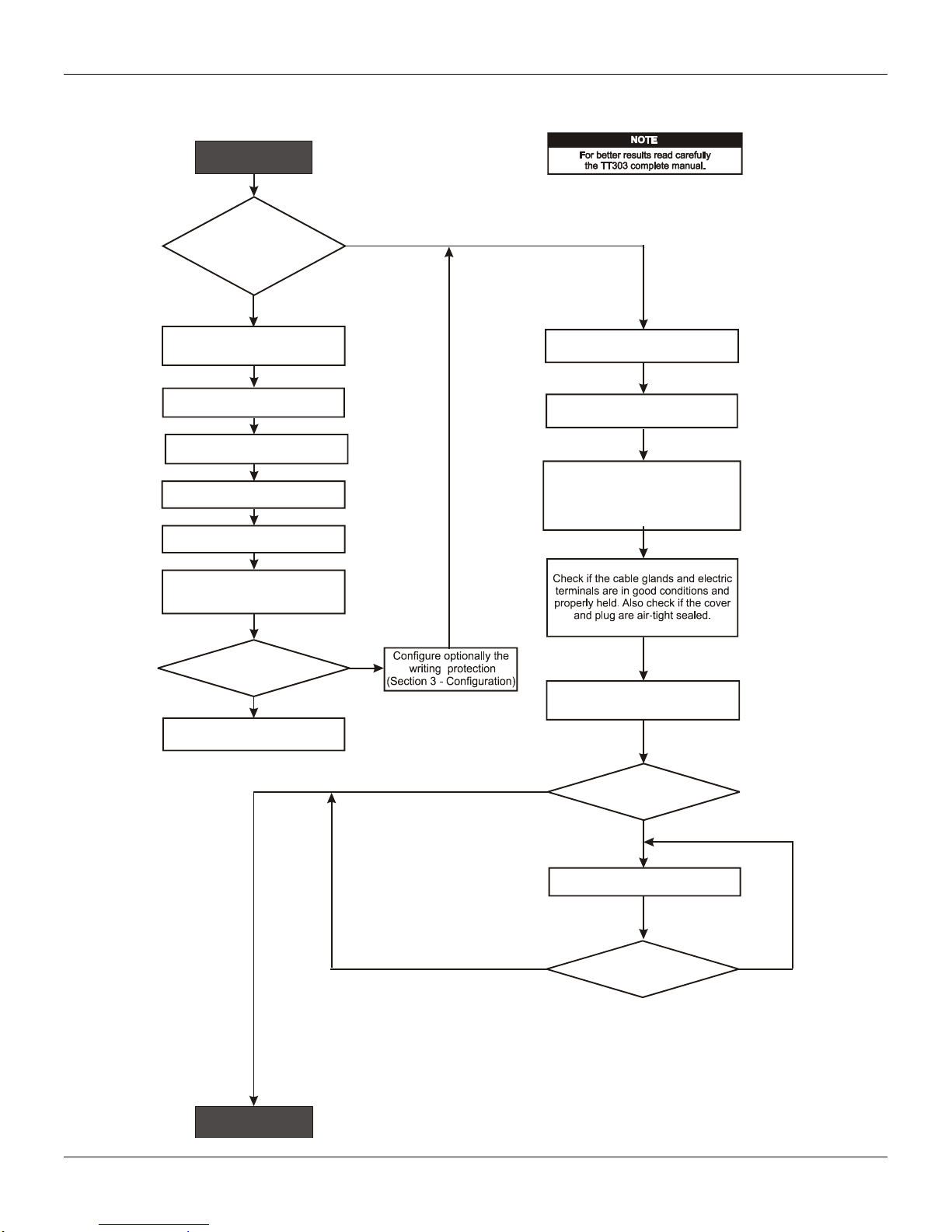
Installation Flowchart
Yes
Was the transmitter
configured on the bench
to match the application?
Configure the range and unit
(AI block)
Simule the value(s)
of the work range in the sensor(s)
conection terminal(s)
mV or Ohm
Start
No
No
OK
Yes
No
Yes
No
Yes
Configure the
1 and
3 - Configuration)
sensor and its
connections (Section
Section
Configure the measuring type
(differantial, dual, backup, or single)
Configure the Damping (AI block)
(Section 3 - Configuration)
Configure the LCD reading
(Section 3 - Configuration)
See manual
(Section 5 - Maintenance)
Is the reading correct?
Check the area classification
and its practices.
Install the transmitter preferably
on weather- protected areas.
Install the transmitter
(mechanically and electrically)
according to the application after
checking the best position for the LCD
(Section 5 - Maintenance)
Power the transmitter properly.
Is the transmitter
reading correct?
Do lower and upper trimTrim
Did you correct the
transmitter reading?

TT303 – Operation and Maintenance Instruction Manual
VIII

Section 1
General
Mounting
Network Wiring
INSTALLATION
The overall accuracy of temperature and other measurements depends on several variables.
Although the transmitter has an outstanding performance, proper installation is essential in order to
maximize its performance.
Among all factors which may affect transmitter accuracy, environmental conditions are the most
difficult to control. There are, however, ways of reducing the effects of temperature, humidity and
vibration.
Locating the transmitter in areas protected from extreme environmental changes can minimize
temperature fluctuation effects.
In warm environments, the transmitter should be installed in such a way as to avoid, as much as
possible, direct exposure to the sun. Installation close to lines and vessels subjected to high
temperatures should also be avoided. For temperature measurements, sensors with cooling-neck
can be used or the sensor can be mounted separately from the transmitter housing.
Use of sunshades or heat shields to protect the transmitter from external heat sources should be
considered.
Humidity is fatal for electronic circuits. In areas subjected to high relative humidity, the O-rings for
the electronic housing covers must be correctly placed and the covers must be completely closed by
tightening them by hand until you feel the O-rings being compressed. Do not use tools to close the
covers. Removal of the electronics cover in the field should be reduced to the minimum necessary,
since each time it is removed, the circuits are exposed to humidity. The electronic circuit is protected
by a humidity proof coating, but frequent exposure to humidity may affect the protection provided. It
is also important to keep the covers tightened in place. Every time they are removed, the threads
are exposed to corrosion, as painting cannot protect these parts. Code-approved sealing methods
should be employed on conduit entering the transmitter.
Connecting the sensor as close to the transmitter as possible and using proper wires (See Section 2
- Operation), can decrease measurement error.
The transmitter may be mounted in two basic ways:
Separated from the sensor, using optional mounting brackets.
Mounted on the sensor assembly.
It can be mounted in several different positions using the bracket, as shown in Figure 1.3. As shown
in Figure 1.3 one of the conduit inlets for electrical connection is used to mount the sensor integral
to the temperature transmitter.
For better visibility, the digital display may be rotated in steps of 90º (see Figure 4.1).
Access the terminal block by removing the Electrical Connection Cover. This cover can be locked
closed by the cover locking screw (See Figure 1.1).To release the cover, rotate the locking screw
clockwise.
1.1

TT303 – Operation and Maintenance Instruction Manual
COVER
LOCKING
SCREW
WARNING
Do not connect the Fieldbus network wires to the sensor terminals. (Terminals 1, 2, 3 and 4).
ALLOW 150 MM MINIMUM FOR LOCAL
ZERO AND SPAN ADJUSTMENT WITH
MAGNETIC TOOL.
COMMUNICATIONS
TERMINAL
PLUG
CONDUIT
CONNECTION
MOUNTING
BRACKET
PIPE 2"
PLUG
WALL OR
PANEL MOUNTING
FOR WALL MOUNTING
2 EXPANSION ANCHOR 2 HEXAGON SCREW -
S8
3/16”X70
2 BOLT AND NUTS - 1/4”X30
NOT INCLUDED
FOR PANEL MOUNTING
POWER SUPPLY
AND COMMUNICATION
(FIELDBUS NETWORK)
TERMINALS
AUXILIARY
COMMUNICATION
TERMINALS
GROUND
TERMINALS
+
1 2 3
4
+
COMM
Figure 1.1 - Cover Locking
Cable access to wiring connections are obtained by one of the two conduit outlets. Conduit threads
should be sealed by means of code-approved sealing methods. The unused outlet connection
should be plugged accordingly.
The wiring block has screws on which fork or ring type terminals can be fastened (see Figure 1.2).
Figure 1.2 - Ground Terminals
For convenience, there are three ground terminals: one inside the cover and two externally,
located close to the conduit entries.
Figure 1.3 - Dimensional Drawing and Mounting Positions
1.2

Installation
NOTE
Please refer to the General Installation, Operation and Maintenance Procedures Manual for more
details.
WIRES
NOTE
Avoid routing sensor wiring close to power cables or switching equipment.
The TT303 uses the 31.25-kbit/s, voltage mode option for the physical signaling. All other devices
on the same bus must use the same signaling. All devices are connected in parallel along the same
pair of wires.
Various types of Fieldbus devices may be connected on the same bus. The TT303 is powered via
the bus. The limit for such devices is according to the DP/PA coupler limitations for one bus for nonintrinsically safe requirement.
In hazardous areas, the number of devices may be limited intrinsically safe restrictions, according to
the DP/PA coupler and barriers limitations.
The TT303 is protected against reverse polarity, and can withstand ±35 VDC without damage, but it
will not operate when in reverse polarity.
Use of twisted pair cables is recommended. It is also recommended to ground shield of shielded
cables at one end only. The non-grounded end must be carefully isolated.
The Figure 1.4 shows the correct installation of the conduit, in order to avoid penetration of water, or
other substance, which may cause malfunctioning of the equipment.
Sensor Wiring
Figure 1.4 - Conduit Installation Diagram
The TT303 accepts up to two sensors and may operate in one of three modes:
Single channel single sensor measurement;
Dual channel dual sensor measurement;
Single channel dual sensor differential measurement;
Single channel dual sensor backup measurement;
In accordance with connection and sensor types, the terminal blocks shall be wired as shown on the
figure 1.5.
1.3

TT303 – Operation and Maintenance Instruction Manual
2 - WIRE RTD OR OHM INPUT
4 - WIRE RTD OR OHM INPUT
DUAL OR DIFFERENTIAL
RTD OR OHM INPUT
DUAL OR DIFFERENTIAL
THERMOCOUPLE OR
MILLIVOLT INPUT
THERMOCOUPLE
INPUT
MILLIVOLT INPUT
3 - WIRE RTD OR OHM INPUT
1 2 3 4
1 2 3 4 1 2 3 4 1 2 3 4
1 2 3 4
1 2 3 4
1 2
DUAL OR DIFFERENCTIAL
RTD AND TC INPUT
3 41 2 3 4
10 M
DUAL OR DIFFERENTIAL
+
+
1 2
10 M
3 4
+
+
+
+
Figure 1.5 - Sensor Wiring
1.4

JUNCTION
BOX
SHIELD
SPUR
SPUR SPUR
TERMINATOR
Analog
Ground
+-+
-
Analog
Ground
+ - +
-
JUNCTION
BOX
TERMINATOR
COUPLER
Topology and Network Configuration
Bus topology (see Figures 1.6 and 1.7) are supported. Both types have a trunk cable with two
terminations. The devices are connected to the trunk via spurs. The spurs may be integrated in the
device giving zero spur length. A spur may connect more than one device, depending on the length.
Active couplers may be used to extend spur length.
Active repeaters may be used to extend the trunk length.
The total cable length, including spurs, between any two devices in the Fieldbus should not exceed
1900 m.
The connection of couplers should be kept less than 15 per 250 m. In following figures the
DP/PA link depends on the application needs.
Installation
Figure 1.6 - Bus Topology
Figure 1.7 - Tree Topology
1.5

TT303 – Operation and Maintenance Instruction Manual
J1
This jumper enables the simulation mode parameter in the AI block.
W1
This jumper enables the local adjustment programming tree.
Intrinsic Safety Barrier
When the Fieldbus is in an area requiring intrinsic safety, a barrier must be inserted on the trunk
between the power supply and the DP/PA coupler, when it is Non-Ex type.
Use of DF47 is recommended.
Jumper Configuration
In order to work properly, the jumpers J1 and W1 located in the TT303 main board must be correctly
configured (See Table 1.1).
Power Supply
The TT303 receives power from the bus via the signal wiring. The power supply may come from a
separate unit or from another device such as a controller or DCS.
The voltage should be between 9 to 32 Vdc for non-intrinsic safe applications.
A special requirement applies to the power supply used in an intrinsically safe bus and depends on
the type of barrier used.
Use of PS302 is recommended as power supply.
Table 1.1 - Description of the Jumpers
1.6

WARNING
Explosions could result in death or serious injury, besides financial damage. Installation of this
transmitter in explosive areas must be carried out in accordance with the local standards and the
protection type adopted .Before continuing the installation make sure the certificate parameters are
in accordance with the classified area where the equipment will be installed.
The instrument modification or parts replacement supplied by other than authorized representative
of Smar is prohibited and will void the certification.
The transmitters are marked with options of the protection type. The certification is valid only when
the protection type is indicated by the user. Once a particular type of protection is selected, any
other type of protection can not be used.
WARNING
Only use Explosion Proof/Flameproof certified Plugs, Adapters and Cable glands.
In Explosion-Proof installations the cable entries must be connected or closed using metal cable
gland and metal blanking plug, both with at least IP66 and Ex-d certification.
The standard plugs provided by Smar are certified according to CEPEL certificate. If the plug
needs to be replaced, a certified plug must be used.
The electrical connection with NPT thread must use waterproofing sealant. A non-hardening
silicone sealant is recommended.
For NEMKO ATEX certificate please to follow the installation guidelines in hazardous locations
below: Group II Category 2G, Ex d, Group IIC, Temperature Class T6, EPL Gb U = 28VDC
Ambient Temperature: -20 to 60ºC for T6
Environmental Protection: IP66/687 or IP66W/687W
The electrical connection available are ½ - 14NPT and M20x1,5.
Cable entries must be connected or closed using metal cable gland and metal blanking plug, both
with at least IP66 and Ex-d certification or any appropriate ATEX approved metal cable gland and
metal blanking plug. Do not remove the transmitter covers when power is ON.
WARNING
In hazardous zones with intrinsically safe or non-incendive requirements, the circuit entity
parameters and applicable installation procedures must be observed.
To protect the application the transmitter must be connected to a barrier. Match the parameters
between barrier and the equipment (Consider the cable parameters). Associated apparatus ground
bus shall be insulated from panels and mounting enclosures. Shield is optional. If used, be sure to
insulate the end not grounded. Cable capacitance and inductance plus Ci and Li must be smaller
than Co and Lo of the associated Apparatus.
It is not recommended to remove the transmitter cover when the power is ON.
Installation in Hazardous Areas
Explosion/Flame Proof
Installation
Intrinsically Safe
1.7

TT303 – Operation and Maintenance Instruction Manual
1.8

Section 2
OPERATION
The TT303 accepts signals from mV generators such as thermocouples or resistive sensors such as
RTDs. The criterion is that the signal is within the range of the input. For mV, the range is -50 to 500
mV and for resistance, 0-2000 Ohm.
Functional Description - Hardware
The function of each block is described below.
Figure 2.1 - TT303 Block Diagram
MUX Multiplexer
The MUX multiplexes the sensor terminals to the signal conditioning section ensuring that the
voltages are measured between the correct terminals.
Signal Conditioner
Its function is to apply the correct gain to the input signals to make them suit the A/D - converter.
A/D Converter
The A/D converts the input signal to a digital format for the CPU.
Signal Isolation
Its function is to isolate the control and data signal between the input and the CPU.
(CPU) Central Processing Unit, RAM, PROM and EEPROM
The CPU is the intelligent portion of the transmitter, being responsible for the management and
operation of measurement, block execution, self-diagnostics and communication. The program is
stored in a PROM. For temporary storage of data there is a RAM. The data in the RAM is lost if the
power is switched off. However there is a nonvolatile EEPROM where data that must be retained is
stored. Examples, of such data are trim, calibration, block configuration and identification data.
Communication Controller
It monitors line activity, modulates and demodulates communication signals and inserts and deletes
start and end delimiters.
2.1
TT303 – Operation and Maintenance Instruction Manual
Power Supply
Takes power of the loop-line to power the transmitter circuitry.
Power Isolation
Just like the signals to and from the input section, the power to the input section must be isolated.
Isolation is achieved by converting the DC supply into a high frequency AC supply and galvanically
separating it using a transformer.
Display Controller
Receives data from the CPU informing which segments of the Liquid Crystal Display, should be
turned on.
Local Adjustment
There are two switches that are magnetically activated. They can be activated by the magnetic tool
without mechanical or electrical contact.
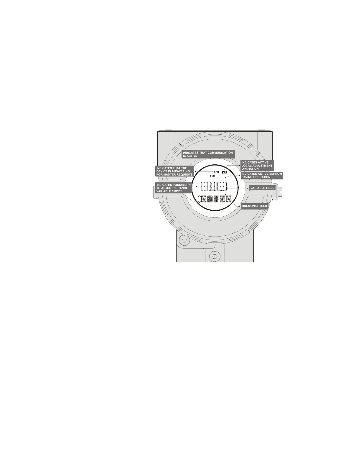
Figure 2.2 - LCD Indicator
Temperature Sensors
The TT303, as previously explained, accepts several types of sensors. The TT303 is specially
designed for temperature measurement using thermocouples or Resistive Temperature Detectors
(RTDs).
Some basic concepts about these sensors are presented below.
Thermocouples
Thermocouples are constructed with two wires made from different metals or alloys joined at one
end, called measuring junction or "hot junction". The measuring junction should be placed at the
point of measurement. The other end of the thermocouple is open and connected to the temperature
transmitter. This point is called reference junction or cold junction.
For most applications, the Seebeck effect is sufficient to explain thermocouple behavior as
following:
How the Thermocouple Works (Seebeck Effect)
When there is a temperature difference along a metal wire, a small electric potential, unique to every
alloy, will occur. This phenomenon is called Seebeck effect. When two wires of dissimilar metals are
joined at one end, and left open at the other, a temperature difference between the two ends will
result in a voltage since the potentials generated by the dissimilar materials are different and do not
cancel each other out. Now, two important things must be noted. First: the voltage generated by the
thermocouple is proportional to the difference between the measuring-junction and the cold junction
temperatures.
2.2

Operation
NOTE
Use thermocouple wires or appropriate extension wires all the way from sensor to transmitter.
R
V2
TRANSMITTER
2,1
3,4
R
RTD
I
Therefore the temperature at the reference junction must be added to the temperature derived from
the thermocouple output, in order to find the temperature measured. This is called cold junction
compensation, and is done automatically by the TT303, which has a temperature sensor at the
sensor terminals for this purpose. Secondly, if the thermocouple wires are not used, all the way to
the terminals of the transmitter (e.g., copper wire is used from sensor-head or marshaling box) will
form new junctions with additional Seebeck effects. It will be created and ruin the measurement in
most cases, since the cold-junction compensation will be done at the wrong point.
The relation between the measuring junction temperature and the generated millivoltage is tabulated
in thermocouple calibration tables for standardized thermocouple types, the reference temperature
being 0C.
Standardized thermocouples that are commercially used, whose tables are stored in the memory of
the TT303, are the following:
NBS (B, E, J, K, N, R, S & T)
DIN (L & U)
Resistive Temperature Detectors (RTDs)
Resistance Temperature Detectors, most commonly known as RTD’s, are based on the principle
that the resistance of metal increases as its temperature increases.
Standardized RTDs, whose tables are stored in the memory of the TT303, are the following:
JIS [1604-81] (Pt50 & Pt100)
IEC, DIN, JIS [1604-89] (Pt50, Pt100 & Pt500)
GE (Cu10)
DIN (Ni120)
For correct measurement of RTD temperature, it is necessary to eliminate the effect of the
resistance of the wires connecting the sensor to the measuring circuit. In some industrial
applications, these wires may be hundreds of meters long. This is particularly important at locations
where the ambient temperature changes constantly.
The TT303 permits a 2-wire connection that may cause measuring errors, depending on the length
of connection wires and on the temperature to which they are exposed. (see Figure 2.3).
In a 2-wire connection, the voltage V2 is proportional to the RTD resistance plus the resistance of
the wires.
V2 = [RTD + 2 x R] x I
Figure 2.3 - Two-Wire Connection
In order to avoid the resistance effect of the connection wires, it is recommended to use a 3-wire
connection (see Figure 2.4) or a 4-wire connection (see Figure 2.5).
In a 3-wire connection, terminal 3 is a high impedance input. Thus, no current flows through that
wire and no voltage drop is caused. The voltage V2-V1 is independent of the wire resistances since
they will be cancelled, and is directly proportional to the RTD resistance alone.
2.3

TT303 – Operation and Maintenance Instruction Manual
R
V2
V1
TRANSMITTER
2,1
4
3
R
RTD
I
R
V2
2
1
+
-
3
4
R
RTD
TRANSMITTER
I
TRANSMITTER
1,3
R
R
R
2
4
V1
V2
RTD2
RTD1
I
I
V2-V1 = [RTD + R] x I - R x I = RTD x I
Figure 2.4 - Three – Wire Connection
In a 4-wire connection, terminals 2 and 3 are high impedance inputs. Thus, no current flows through
those wires and no voltage drop is caused. The resistance of the other two wires is not of interest,
since there is no measurement registered on them. Hence the voltage V2 is directly proportional to
the RTD resistance.
(V2 = RTD x I)
Figure 2.5 - Four - Wire Connection
A differential or dual channel connection is similar to the two-wire connection and gives the same
problem (See Figure 2.6). The resistance of the wires will be measured and do not cancel each
other out in a temperature measurement, since linearization will affect them differently.
2.4
Figure 2.6 - Differential or Dual Connection

* PID IS OPTIONAL
M
A
Fix
F(t)
PID
SP
F(x)
35
PV
min
ACK
INDICATES THAT THE DISPLAYED
ALARM HAS NOT YET BEEN ACKNOWLEDGED
INDICATES ACTIVE SPECIAL
SENSOR LINEARIZATION
( NOT USED ON TT301 )
VARIABLE FIELD
UNIT PERCENT
UNIT MINUTES
UNIT AND FUNCTION FIELD
INDICATES THAT THE PROCESS
VARIABLE IS NOW DISPLAYED
INDICATES ACTIVE
MULTIDROP MODE
INDICATES ACTIVE
SETPOINT GENERATOR *
INDICATE PID
CONTROLLER MODE *
INDICATES ACTIVE
CONSTANT OUTPUT MODE
INDICATES CONTROLLER
IN AUTOMATIC *
INDICATES CONTROLLER
IN MANUAL *
INDICATES POSSIBILITY
TO ADJUST / CHANGE
VARIABLE / MODE
INDICATES THAT
THE SETPOINT
The Display
Operation
The digital indicator is able to display one or two variables which are user selectable. When two
variables are chosen, the display will alternate between the two with an interval of 3 seconds.
The different fields and status indicators are explained in Figure 2.7.
Monitoring
Figure 2.7 – Typical Monitoring Mode Display
During normal operation, the TT303 is in the monitoring mode. In this mode, indication alternates
between the primary and secondary variable as configured in DISPLAY. See Figure 2.8.
The display indicates engineering units, values and parameters simultaneously with most status
indicators. The monitoring mode is interrupted in two situations:
User performs complete local adjustment.
An alarm is activated.
Figure 2.7 – Display
2.5

TT303 – Operation and Maintenance Instruction Manual
ALARM 1
ALARM 2
Alarm
The two alarms are software alarms and have no contacts available on the transmitter. The alarms
are acknowledged by using the Local Adjustment or the Configurator, which can view and configure
alarms as well - see further Section III. During an alarm, the display will indicate which alarm has
been activated and if it has been acknowledged or not.
The transmitter display also indicates the alarms status as shown in Figure 2.9.
AL H means High Alarm, AL L means Low Alarm and ALO indicates Burnout failure. The ACK
indicates that the alarm has not yet been acknowledged.
When the alarm condition disappears, the "ACK" is switched off and the display returns to
monitoring mode.
For further information on alarm configuration, see Section III - Programming Using Terminal.
Figure 2.9 – Typical Alarm Condition Display
2.6

Section 3
CONFIGURATION
This section describes the characteristics of the blocks in the TT303. They follow the Profibus PA
specifications, but in terms of transducer blocks, the input transducer block and display, they have
some special features on top of this.
The TT303 contains two input transducer blocks, one resource block, one display transducer block.
For explanation and details of function blocks, see the “Function Blocks Instruction Manual”.
The 303 Smar family is integrated in Profibus View, from Smar and in the Simatic PDM, from
Siemens. It is possible to integrate any 303 Smar device into any configuration to ol for Profibus PA
devices. It is necessary to provide a Device Description or Drive acc ording to the configuration too l.
In this manual is taken several examples using Profibus View or Simatic PDM.
In order to assure correct values in the offline configuration, first run “Download to PG/PC” option to
assure valid values. After, run the Menu Device option to configur e the required parameters using
the related menus.
In offline configuration, it is not advisable to use the “Download to Device” option. This function can
misconfigure the equipment.
Transducer Block
Transducer block insulates function blocks from the specific I/O hardware, such as sensors,
actuators. Transducer block controls access to I/O through manufacturer specific implementation.
This permits the transducer block to execute as frequently as nec essary to obtain good data from
sensors without burdening the function blocks that uses the data. It also insulates the function block
from the manufacturer specific characteristics of certain hardware.
By accessing the hardware, the transducer block can get data from I/O or passing control data to it.
The connection between Transducer block and Function block is called channel. T hese blocks can
exchange data from its interface.
Normally, transducer blocks perform functions, such as linearization, characterization, temperature
compensation, control and exchange data to hardware.
How to Configure a Transducer Block
The transducer block has an algorithm, a set of contained p arameters, it means, yo u are not able t o
link these parameters to other blocks and publish the link via communication, and a channel
connecting it to a function block.
The algorithm describes the behavior of the transducer as a data transfer function between the I/O
hardware and other function block. The set of contained parameters defi nes the user interface to the
transducer block. They can be divided into Standard and Manufacturer Specific.
The standard parameters will be present for such class of device, as pressure, temperature,
actuator, etc., whatever is the manufacturer. Oppositely, the manufacturers specific ones are
defined only for its manufacturer. As common manufacturer specific parameters, we have calibration
settings, material information, linearization curve, etc.
When you perform a standard routine such as calibration, you are conducted step by step by a
method. The method is generally defined as guideline to help the user to make c ommon tasks. The
Configuration Tool identifies each method associated to the parameters and enables the i nterface
to it.
NOTE
3.1

TT303 – Operation and Maintenance Instruction Manual
x
Functional Diagram of the Temperature Transducer Block
Transducer BlockProcess Transducer Block AI FB(’s)
R.J.
Input
T1
T2
Input 1
Input 2
INPUT_RANGE,
SENSOR_CONNECTION,
COMP_WIRE1/2
RJ_TEMP
RJ_TYPE
R.J. Comp.
LIN
+
0
1 2 EXTERNAL_RJ_VALUE
Linearization
LIN
+
TAB_...
LIN
Arithmetic
BIAS_1
SECONDARY_VALUE_1
+
PRIMARY_VALUE
+
SECONDARY_VALUE_2
BIAS_2
SENSOR_MEAS_TYPELIN_TYPE,
Figure 3.1 – Functional Diafram of the Temperature Block
Temperature Transducer Block General Parameter Description
Temperature Transducer Block General Parameter Description formatted: font: Not Bold, English
(U.S.)
PARAMETER DESCRIPTION
BIAS_1
BIAS_2
INPUT_FAULT_GEN
INPUT_FAULT_1
Bias that can be algebraically added to process value of channel 1.
The unit of BIAS_1 is the PRIMARY_VALUE_UNI T.
Bias that can be algebraically added to process value of channel 2.
The unit of BIAS_2 is the PRIMARY_VALUE_UNI T.
Input malfunction: Diagnosis object for errors that concerns all values
0 = device OK
Bit:
0 = Rj error
1 = Hardware error
2 – 4 = reserved
5 – 7 = manufacturer specific
Byte:
0x00: status ok;
0x80: hardware failure
Input malfunction: Diagnosis object for errors that concern SV_1
0 = Input OK
Bit:
0 = underrange
1 = overrange
2 = lead breakage
3 = short circuit
4 – 5 = reserved
6 – 7 = manufacturer specific
Byte:
0x00: input ok;
0
x8800:: sseennssoorr ffaaiilluurree
0
3.2

INPUT_FAULT_2
INPUT_RANGE
LIN_TYPE
PARAMETER DESCRIPTION
Input malfunction: Diagnosis object for errors that concern SV_2
0 = Input OK
Bit and byte definition see INPUT_FAULT_1
Electrical input ran ge and mode. The ranges are manufacturer specific but range n is smaller than range n+1
if more than one range is supported for one input mode (e.g. range1=0...400
INPUT_RANGE is equal for channel 1 and 2.
Defined codes (other codes are reserv ed):
0 = mV range 1 => mV22
1 = mV range 2 => mV100
2 = mV range 3=> mV500
:
9 = mV range 10
128 =
:
137 = range 10
192 = mA range 1
193 = mA range 2
:
201 = mA range 10
240 = manufacturer specific
:
249 = manufacturer specific
250 = not used
251 = none
252 = unknown
253 = special
Remark:
When using codes 240..249 (manufacturer specific) interchangeability is not possible.
Select the type of sensor (Code) for Thermocouples, Rtd, Pyrometers or linear.
101 = RTD Pt50 a=0.003850 (IEC 751, DIN 43760, JIS C1604-97, BS1904)
102 = RTD Pt100 a=0.003850 (IEC 751, DIN 43760, JIS C1604-97, BS1904)
104 = RTD Pt500 a=0.003850 (IEC 751, DIN 43760, JIS C1604-97, BS1904)
107 = RTD Pt50 a=0.003916 (JIS C1604-81)
108 = RTD Pt100 a=0.003916 (JIS C1604-81)
120 = RTD Ni120 a=0.006720 (Edison curve #7)
121 = TC Type E, Ni10Cr-Cu45Ni (IEC584, NIST MN 175, DIN 43710, BS 4937, ANSI MC96.1, JIS
C1602, NF C42-321)
128 = TC Type B, Pt30Rh-Pt6Rh (IEC 584, NIST MN 175, DIN 43710, BS 4937, ANSI MC96.1, JIS
C1602, NF C42-321)
133 = TC Type J, Fe-Cu45Ni (IEC 584, NIST MN 175, DIN 43710, BS 4937, ANSI MC96.1, JIS C1602,
NF C42-321)
134 = TC Type K, Ni10Cr-Ni5 (IEC 584, NIST MN 175, DIN 43710, BS 4937, ANSI MC96.1, JIS C1602,
NF C42-321)
135 = TC Type N, Ni14CrSi-NiSi (IEC 584, NIST MN 175, DIN 43710, BS 4937, ANSI MC96.1, JIS
C1602, NF C42-321)
136 = TC Type R, Pt13Rh-Pt (IEC 584, NIST MN 175, DIN 43710, BS 4937, ANSI MC96.1, JIS C1602,
NF C42-321)
137 = TC Type S, Pt10Rh-Pt (IEC 584, NIST MN 175, DIN 43710, BS 4937, ANSI MC96.1, JIS C1602,
NF C42-321)
138 = TC Type T, Cu-Cu45Ni (IEC 584, NIST MN 175, DIN 43710, BS 4937, ANSI MC96.1, JIS C1602,
NF C42-321)
139 = TC Type L, Fe-CuNi (DIN 43710)
140 = TC Type U, Cu-CuNi (DIN 43710)
145 to 239 reserved
Manufacturer specific :
240 Cu10 GE, Edison #15
241 Ohm 100
242 Ohm 400
243 Ohm 2000
244 mV22
245 mV100
246 mV500
:
249 Manufacturer specific
250 Not used
251 None
252 Unknown
253 Special
range 1 = > Ohm 100
129 = range 2 = > Ohm 400
130 = range 3 = > Ohm 2000
Configuration
, range2=0...4k).
3.3

TT303 – Operation and Maintenance Instruction Manual
PARAMETER DESCRIPTION
Physical lower limit function of sensor (e.g. Pt 100 = -200°C) and input range. In the case of multichannel
LOWER_SENSOR_LIMIT
PRIMARY_VALUE
PRIMARY_VALUE_UNIT
SECONDARY_VALUE_1
(SV_1)
SECONDARY_VALUE_2
(SV_2)
SENSOR_MEAS_TYPE
UPPER_SENSOR_LIMIT
COMP_WIRE1 Value in OHM to compensate line resistance when the thermoresistance 1 is connected with 2 or 3 wires.
COMP_WIRE2 Value in OHM to compensate line resistance when the thermoresistance 2 is connected with 2 or 3 wires.
SENSOR_CONNECTION
PRIMARY_VALUE_RANGE
CAL_POINT_HI
CAL_POINT_LO
CAL_MIN_SPAN
CAL_UNIT
SENSOR_RANGE
SENSOR_SN The sensor serial number.
SECONDARY_VALUE The secondary value related to the sensor .
SECONDARY_UNIT The engineering units to be used with the secondary value related to the sensor.
MODULE_SN Indicates the number of the module.
SECONDARY_VALUE_ACTION
TWO_WIRES_COMPENSATION
SENSOR_TRANSDUCER_NUMBER Selects the Transducer 1 or 2.
FACTORY_DIGITAL_INPUTS Reads the digital inputs.
FACTORY_GAIN_REFERENCE Calibration point for Ohm and mV sensors.
FACTORY_TERMINAL_REFERENCE Calibration point for the Borne Resistance .
BACKUP_RESTORE
measurements (e.g. differential measurement) the meaning of LOWER_SENSOR_LIMIT is the limit of one
channel not the calculated limit of both channels.
The unit of LOWER_SENSOR_LIMIT is the PRIMARY_VALUE_UNIT.
Process value, function of SECONDARY_VALUE_1/2.
The unit of PRIMARY_VALUE is the PRIMARY_VALUE_ UNIT.
Show the unit code of the PRIMARY_VALUE and other values. The unit is select using
PRIMARY_VALUE_RANGE parameter.
Set of unit codes:
1000: K (Kelvin)
1001: °C (degree Celsius)
1002: °F (degree Fahrenheit)
1003: Rk (Rankine)
1281: (Ohm)
1243: mV (milivolt)
Process value connected to the channel 1 corrected by BIAS_1. The unit of SECONDARY_VALUE_1 is the
PRIMARY_VALUE_UNIT.
Process value connected to the channel 2 corrected by BIAS_2. The unit of SECONDARY_VALUE_2 is the
PRIMARY_VALUE_UNIT.
Mathematical function to calculate PRIMARY_VALUE (PV).
Defined codes:
128: PV = SV_1 - SV_2 Difference
manufacturer specific:
220: = Backup
230: = Process Temperature
Physical upper limit function of sensor (e.g. Pt 100 = 850°C) and input range. In the case of multichannel
measurements (e.g. differential me asurement) the meaning of UPPER_SENSOR_LIMIT is the limit of one
channel not the calculated limit of both channels.
The unit of UPPER_SENSOR_LIMIT is the PRIMARY_VALUE_UNIT.
Connection to the sensor, select for 2, 3 and 4 wires connection.
Defined codes:
0 = 2 wires
1 = 3 wires
2 = 4 wires
3 = 2 dual wires
The high and low range limits values, the engineering units and the number of digits to the right of the
decimal to be used to display the primary value.
This parameter contains the highest calibrated value. For calibration of the high limit point you give the high
measurement value (temperature) to the sensor and transfer this point as HIGH to the transmitter. Unit
derives from CAL_UNIT.
This parameter contains the lowest calibrated value. For calibration of the low limit point you give the low
measurement value (temperature) to the sensor an d tran sfer this point as LOW to the transmitter. Unit
derives from CAL_UNIT.
This parameter contains the minimum calibration span value allowed. This minimum span information is
necessary to ensure that when calibration is done, the two calibrated points (high and low) are not too close
together. Unit derives from CAL_UNIT.
The unit for calibration process:
{1000, "Kelvin"},
{1001, "Celsius"},
{1002, "Fahrenheit"},
{1003, "Rankie"}
{1243, "mV"}
{1281, "Ohm"}
The high and low range limits values, the engineering units and the number of digits to the right of the
decimal to be used to describe the operating limits for the sensor.
Allows to enable and to disable the cold junction.
{0, "Disable"},
{1, "Enable"}
Allows the compensation of line resistance for double RTD or Ohm sensors.
{0, "Disable"},
{1, "Enable"}
This parameter allows to save and to restore data according to factory and user calibration procedures. It has
the following options:
3.4

Configuration
PARAMETER DESCRIPTION
1, "Factory Cal Restore",
2, "Last Cal Restore",
3, "Default Data Restore",
11, "Factory Cal Backup",
12, "Last Cal Backup",
14, "Shut-Down Data Backup",
0, "None".
Indicates the condition of calibration process according to:
{16, "Default value set"},
XD_ERROR
{22, "Applied process out of range"},
{26, "Invalid configuration for request"},
{27, "Excess correction"},
{28, "Calibration failed"}
EEPROM_FLAG This parameter is used to indicate EEPROM saving process.
MAIN_BOARD_SN This is the main board serial number.
ORDERING_CODE Indicates information about the sensor and control from production factory.
Table 3.1 - Parameter Description
Temperature Transducer Block General Parameter Attributes
Temperature Transducer Block General Parameter Attributes
Relative
Index
... Standard Parameter see General Requirements
General Parameter for Temperature Transducer Block
8 PRIMARY_VALUE simple DS-33 D 5 r C/a M 1
9 PRIMARY_VALUE_UNIT simple Unsigned 16 S 2 r,w C/a 2 M
10 SECONDARY_VALUE_1 simple DS-33 D 5 r C/a M
11 SECONDARY_VALUE_2 simple DS-33 D 5 r C/a O
12 SENSOR_MEAS_TYPE simple unsigned 8 S 1 r,w C/a 3 M
13 INPUT_RANGE simple unsigned 8 S 1 r,w C/a 4 M
14 LIN_TYPE See General Requirements. 1 M
19 BIAS_1 simple Float S 4 r,w C/a 0.0 5 M
20 BIAS_2 simple Float S 4 r,w C/a 0.0 O
21 UPPER_SENSOR_LIMIT simple Float N 4 r C/a M
22 LOWER_SENSOR_LIMIT simple Float N 4 r C/a M
24 INPUT_FAULT_GEN simple unsigned 8 D 1 r C/a M 1
25 INPUT_FAULT_1 simple unsigned 8 D 1 r C/a M 1
26 INPUT_FAULT_2 simple unsigned 8 D 1 r C/a O
27-35 Not used
36 SENSOR_CONNECTION simple unsigned 8 S 1 r,w C/a 7 M
37 COMP_WIRE1 simple Float S 4 r,w C/a 0.0 8 M
38 COMP_WIRE2 simple Float S 4 r,w C/a 0.0 O
39 – 61 Not used
62 PRIMARY_VALUE_RANGE record DS-36 S 11 r,w C/a
63 CAL_POINT_HI simple Float S 4 r,w C/a 850.0
64 CAL_POINT_LO simple Float S 4 r,w C/a -200.0
65 CAL_MIN_SPAN simple Float S 4 r C/a 10.0
66 CAL_UNIT simple Unsigned 16 S 2 r,w C/a 1001
67 SENSOR_RANGE record DS-36 N 11 r C/a
68 SENSOR_SN simple Unsigned 32 S 4 r,w C/a
69 SECONDARY_VALUE simple DS-33 D 5 r C/a
70 SECONDARY_VALUE_UNIT simple Unsigned 16 S 2 r,w C/a 1001
Parameter Name
Object
type
Data type Store Size Access
Param. Usage/
Type of
Transport
Default
Value
Download
Order
Mandatory
Optional
(Class)
View
3.5

TT303 – Operation and Maintenance Instruction Manual
Relative
Index
71 MODULE_SN simple Unsigned 32 S 4 r,w C/a
72 SECONDARY_VALUE_ ACTION simple Unsigned 8 S 1 r,w C/a
73 TWO_WIRES_COMPENSA-TION simple Unsigned 8 S 1 r,w C/a
74 SENSOR_TRANSDUCER_
75 FACTORY_DIGITAL_INPUTS simple Float N 4 r,w C/a
76 FACTORY_GAIN_ REFERENCE simple Unsigned 8 S 1 r,w C/a
77 FACTORY_BORNE_
78 BACKUP_RESTORE simple Unsigned 8 S 1 r,w C/a
79 XD_ERROR simple Unsigned 8 D 1 r C/a
80 MAIN_BOARD_SN simple Unsigned 32 S 4 r,w C/a
81 EEPROM_FLAG simple Unsigned 8 D 1 r C/a
82 ORDERING_CODE simple Unsigned 8 S 50 r,w C/a
Parameter Name
NUMBER
REFERENCE
Object
type
simple Unsigned 8 S 1 r,w C/a
simple Unsigned 8 S 1 r,w C/a
Data type Store Size Access
Param. Usage/
Type of
Transport
Default
Value
Download
Order
Mandatory
Optional
(Class)
View
Table 3.2 - General Parameter for Temperature Transducer Block
TT303 - Cyclic Configuration
The PROFIBUS-DP and PROFIBUS-PA protocols have mechanisms against communication
failures between the slave device and the net work master. For example, during initialization, these
mechanisms are used to check these possible errors. After powering up the field devic e (slave), it
can cyclically exchange information with the class 1 master, if the parameterization for the slave is
correct. This information is obtained using the GSD files (supplied by the device manufacturer, it
contains their descriptions). Through the commands below, the master executes all initialization
process with the PROFIBUS-PA device:
Get_Cfg: uploads the slave configuration on the master and checks network configuration;
Set_Prm: writes to the slave parameters and executes the parameterization network;
Set_Cfg: configures the slaves according to its outputs and inputs;
Get_Cfg: another command, where the master checks the slave configuration.
All these services are based on the information obta ined from slave gsd files. The GSD file from
TT303 shows details such as, hardware and software revision, device bus timing and information
about cyclic data exchange. TT303 has 1 functional block: AI.
Most PROFIBUS configuration tools use two directories where the different manufacturers’ GSD’s
and BITMAPS files are stored. The GSD’s and BITMAPS for Smar devices can be obtained through
the website: (https://www.smar.com), on the ‘download’ link.
The following example shows the necessary steps to integrate the TT303 on a Profibus system.
These steps are valid for the entire 303 line of Smar devices:
Copy the TT303 gsd file to the research directory of the PROFIBUS configur ation tool, usually
called GSD;
Copy the TT303 bitmap file to the research directory of the PROFIBUS configur ation tool usuall y
called BMP;
After choosing the master, def ine the baud rate for the net work. Do not forget that couplers may
work with the following baud rate: 45.45 kbits/s (Siemens model), 93.75 kbits/s (P+F model) and
12 Mbits/s (P+F, SK2 model). The IM157 device link (Siemens model) may work up to 12
Mbits/s;
3.6
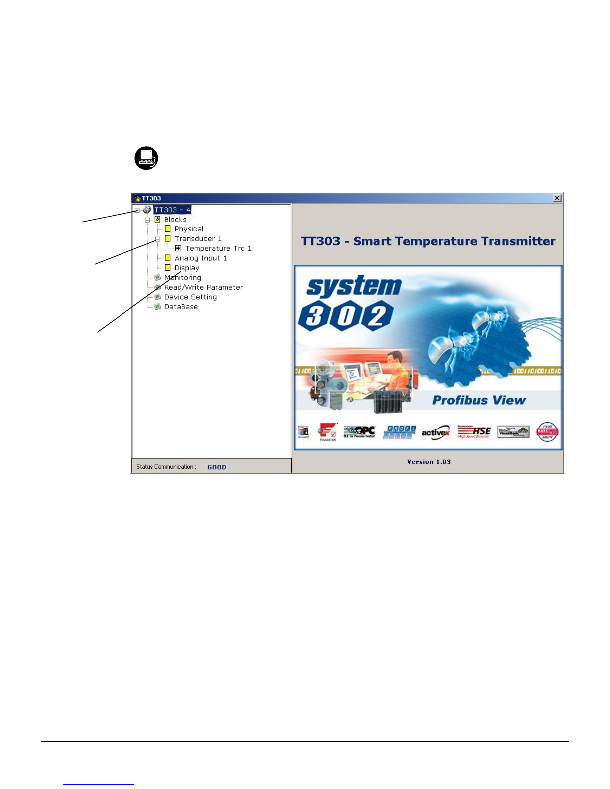
The device was
created as
TT303.
Here, you can
see all blocks
instantiated.
As you can see
the Transducer
and Display are
treated as
special type of
Function
Blocks, called
Transducer
Blocks.
Configuration
Add the TT303 and specify its physical bus address;
Choose the cyclic configuration via parameterization using the gsd file that depends on the
application, as detailed previously. For every AI (Analog Input) block, the TT303 provides the
process variable to the master in 5 bytes value, being the first four according to float point data
type and the fifth byte is the status that brings the measure quality of this information;
It allows activating the condition of watchdog, which the device goes to a fail safe condition,
when a loss of communication is detected with the master.
Configuration softwares like Profibus View from Smar or Simatic PDM (Process Device Manager)
from Siemens can configure many parameters of the Input Transducer block. See the figures 3.2
and 3.3.
Figura 3.2 – Profibus View – Function and Transducers Block
3.7
TT303 – Operation and Maintenance Instruction Manual
Figure 3.3 – PDM Simatic - Function and Transducers Blocks
Use this menu:
- To change the device address;
- To make the up/download of parameters;
- To configure the Transducer Blocks, Analog Blocks and Display Block;
- To calibrate the transmitter;
- To make the reset by software, to protect the device against writing and to
simulate the value from transducer block to analog block;
- To save and restore data calibration.
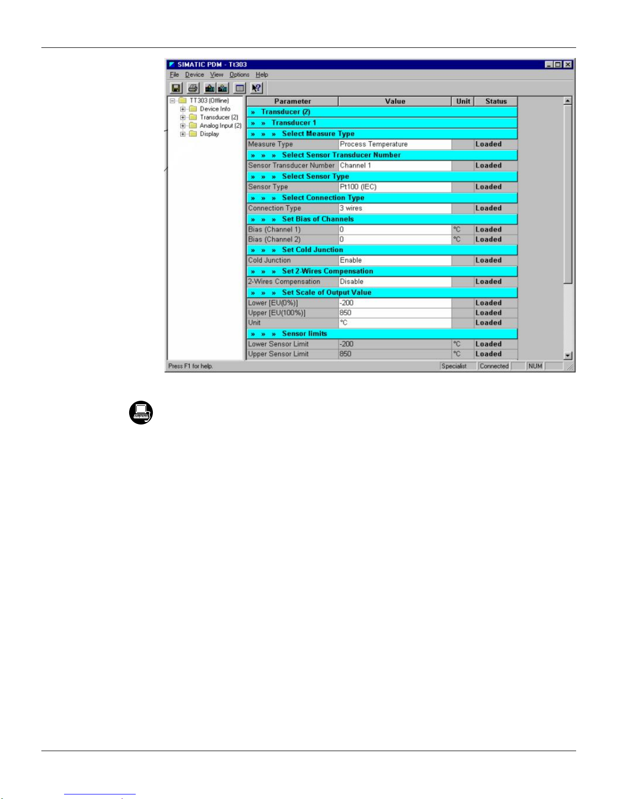
To make the configuration of Transducer Block, we need to select the Transducer 1 block on the
main menu.
3.8
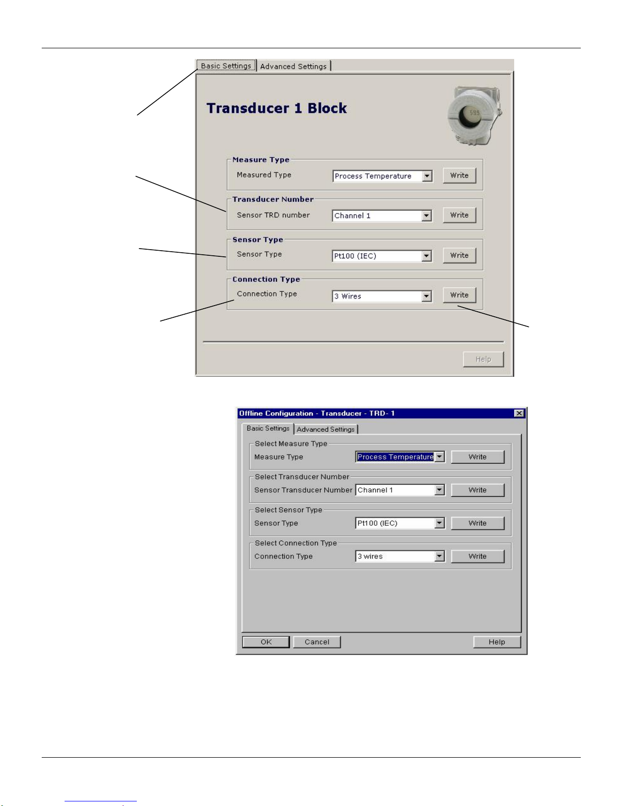
p
The user can select
the Measured type:
T1-T2, Process
Temperature or
.
Backu
The user can set the
sensor transducer
number.
Please, select sensor type
according to the
application and the
connection type.
Configuration
This parameter selects the
type of sensor connection.
The options here will depend
on Sensor Type chosen as
described above.
After selecting
the desired
option, this
key should be
pressed.
Figure 3.4 - Profibus View - Transducer Basic Settings
The user can configure the Transducer Block, accordin g to the selected Measure Type (when you
have selected "Process Temperature", it means that you will have two sensors, two transducer
blocks and two analog input blocks). Please, select the parameters according to your application.
Figure 3.5 – PDM Simatic - Offline Configuration - Transducer Basic Settings
3.9

TT303 – Operation and Maintenance Instruction Manual
It is possible to configure connection and sensor type by means of parameters SENSOR_TYPE and
SENSOR_CONNECTION. The connection and sensor types available are listed in the t ables Table
3.6 and Table 3.7.
Using the "Advanced Settings" window, the user can set the scaling and unit for the output value
according to the Transducer Block Diagram, bias of chann els and set the cold junction and 2- wires
compensation according to his application.
The user can
configure the
scale an unit
for the output
value.
The user can
configure the bias
of channels.
The user can set the
cold junction and the
2-wires compensation.
Figure 3.6 – Profibus View - Transducer Advanced Settings
Figure 3.7 – PDM Simatic - Offline Configuration - Transducer Advanced Settings
Sensor Transducer Number
The Sensor Transducer Number associates the sensor to the transducer. It can be set to channe l
one up to channel two, in case of dual sensor.
3.10

Jumper Configuration
In order to work properly, the jumpers J1 and J3 located in the TT303 main board must be correctly
configured.
J1 is responsible to enable the AI block simulate mode.
W1 is responsable to enable the local adjustment.
There are no 3 or 4 wire connections for mile-voltage sensors.
Configuration
NOTE
SENSOR_TYPE
Pt 100 IEC
Pt 100 JIS
Pt 500 IEC
Ni 120 DIN
Cu 10 CE
Pt 50 IEC
Pt 50 JIS
Ohm 100
Ohm 400
Ohm 2,000
TC B NBS
TC E NBS
TC J NBS
TC K NBS
TC N NBS
TC R NBS
TC S NBS
TC T NBS
TC L DIN
TC U DIN
mV 22
mV 100
mV 500
Table 3.3 - Sensor Type Table
CONNECTION
DOUBLE TWO WIRE
TWO WIRE
THREE WIRE
FOUR WIRE
Table 3.4 - Type of Connection Table
3.11

TT303 – Operation and Maintenance Instruction Manual
How to Connect Two Sensors
Transmitter series TT303 are capable of operating simultaneously with two sensors, using two
transducer blocks, if necessary. Configuration types in two sensors operation are as follows:
Differential – In this case there is only one transducer. Transducer output is the difference bet ween
the readout of sensor 1 (between terminals 3 and 4) and the readout of sensor 2 (between terminals
2 and 4).
Backup - In this case there is only one transducer.
If the first sensor (connected between terminals 3 and 4) opens, the second sensor (connected
between terminals 2 and 4) will supply the signal to the transducer.
Process Temperature - In this case there are t wo transducers. Each s ensor provides a signa l to its
respective transducer. In this case, please select the sensor connection to “2 dual wires ".
In order to be able to operate with sensors in the backup or differential modes, the user shall actuate
parameter MEASURED_TYPE. In order to operate with double sensors, the user shall actuate
parameter SENSOR_CONNECTION. Please see figure 3.4 e 3.5.
Compensation of Line Resistance for RTD Double Sensor or Ohm Sensor
TT303 allows connecting two sensors but it is possi ble just using 2 wires and this can cause an
error due to the absence of compensation of line resistance. T o minimize this error, there is the
TWO_WIRES_COMPENSATION parameter that enables the calculation of line resistance.
To make the compensation it is necessary to set RTD or Ohm with 2 dual wires in the LIN_TYPE
parameter (relative index 14) and then make a short circuit between 1 and 3 terminals. After that it is
necessary to make a short circuit between 3 and 4 terminals (in the wires in the sensor
location).Then enable the TWO_WIRES_COMPENSATION parameter (relative index 73). After that,
verify the PRIMARY_VALUE parameter.
Repeat the same procedure for the second transducer, keeping the s hort circuit between 1 and 3
terminals, but making a short circuit between 2 and 4 terminals. Please see figure 3.6 e 3.7.
Compensation of Cold Junction
TT303 allows the compensation of cold junction when the user select "Enable" according to the
Figure 3.6 e 3.7.
Calibration in TT303 by the User
The electronics of TT303 is very stable in time, not requiring further calibrations after manufacturer’s
calibration. However, should the client decide to use his r eference to calibrate the TT303 (which is
not recommendable), this may be done by means of parameters CAL_POINT_LO and
CAL_POINT_HI. When trim is performed, always use two points as reference; never consider onl y
one point as a reference. Using Profibus View or the Simatic PDM, the calibration is done
selecting at the main menu "Calibration - Transducer TRD1-Lower/Upper" or menu Calibration Transducer TRD2-Lower/Upper".
3.12

Configuration
The user can select
lower or upper
calibration.
The user can see the
lower sensor limit and
the actual calibrated
point. The user just
needs to inform the
desired point.
The user can see the
measured temperature
The user can verify
the calibration
operation result.
and its status.
Figure 3.8 – Profibus View - Lower Calibration Procedures
If the user to select the upper page (UPPER):
Figure 3.9 – PDM Simatic - Lower Calibration Procedure
3.13

TT303 – Operation and Maintenance Instruction Manual
p
The user can see
the upper sensor
limit and the actual
calibrated point. The
use just needs to
inform the desired
The user can
verify the
calibration
o
eration result.
The user can see
the measured
temperature and
its status.
Figure 3.10 – Profibus View - Upper Calibration Procedures
Every time the sensor is altered, TRIM values are reset. In the case of TC it is necessary to
disable the cold junction compensation before starting calibration procedures. Trim is not
available for TT using two sensors.
How to Configure the Analog Input Block
The Analog Input block takes the input data from the Transducer block, selected by channel
number, and makes it available to other function blocks at its output. The transducer bloc k provides
the input unit of the Analog Input, and when the unit is changed in the transduc er, the PV_SCALE
unit is changed too. Optionally, a filter may be applied in the process value signal, whose time
constant is PV_FTIME. Considering a step change to the input, this is the time in seconds to the PV
reaches 63.2% of the final value. If the PV_FTIME value is zero, the fi lter is disabled. For more
details, please, see the Function Blocks Specifications. To configure the Analog Input Block, please,
select the Analog Input Block, in the main menu. Select the analog block according to the
application. Using this window, the user can configure the block mode operation, selects the
channel, scales and unit for input and output value and the damping.
3.14
Figure 3.11 – PDM Simatic - Upper Calibration Procedure
NOTE

Configuration
The user can set
the block mode
operation.
The user
can select
PV, Sec
Value 1 or
Scale of input
value. The
unit comes
from the
Sec Value 2
for the
channel.
parameter.
transducer
block.
Scales and
unit for the
output value.
The user can
set the PV
damping value.
Figure 3.12 – Profibus View - Basic Settings for Analog Input Block
Figure 3.13 – PDM Simatic - Basic Settings for Analog Input Block
Selecting the page "Advanced Settings", the user can configure the conditions for alarms and
warnings, as well the fail safe condition. Please, see the window:
3.15

TT303 – Operation and Maintenance Instruction Manual
The user can set
Alarm/Warning limits.
The fail safe
conditions.
Figure 3.14 – Profibus View - Advanced Settings for Analog Input Block
3.16
Figure 3.15 – PDM Simatic - Advanced Settings for Analog Input Block

Configuration
The user can
set the mode
block
operation.
The user can
monitor the
output
parameter
and verify the
current state
alarm.
Figure 3.16 – Profibus View - Analog Input Block
Figure 3.17 – PDM Simatic - Online Configuration for Analog Input Block
Programming Using Local Adjustment
The local adjustment is completely configured by Profibus View or Simatic PDM or any other
configuration tool. It means that the user can select the best options to fit his application. From
factory, it is configured with the options to set the Upper and Lower trim, for monitoring the input
transducer output and check the Tag. Normally, the transmitter is much better configured by
configuratinon tool, but the local functionality of the LCD permits an easy and fast action on
certain parameters, since it does not rely on communication and network wiring connections. Among
the possibilities by Local Adjustment, the following options can be emphasized: Mode Block,
Outputs Monitoring, Tag Visualization and Tuning Parameters Setting.
3.17

TT303 – Operation and Maintenance Instruction Manual
User´s interface is also described very detailed on the "General Installation, Operation and
Maintenance Procedures Manual". Please take a detailed look at this manua l in the chapter related
to "Programming Using Local Adjustment". The resources on this transducer display are very
signifcant, and all of the Series 303 field devices from SMAR has the sa me methodology to handle
with it. So, since the user has learned once, he is capable to handle all kind of field devices from
SMAR. This Local Adjustment is a suggestion only. The user may choose his preferred
configuration via configuration toll, simply setting the display block).
The positioner has two holes for magnetic switches, located u nder the identification plate. These
magnetic switches are activeted by a magnetic tool.
This magnetic tool enables adjustment of the most important parameters of the blocks. It also
enables pre-configuration of the communication.
The jumper W1 on top of the main circuit board must be i n place and the positioner must be fitted
with digital display for access to the local adjustment. Without dis play, the local adjustment is not
possible.
Figure 3.18 - Local Adjustment Holes
Table 3.5 shows the actions on the Z and S holes on the TT303 when Local Adjustment is enable d.
HOLE ACTION
Z
S
Inicializes and rotates through the available functions.
Selects the function shown in the display.
Table 3.5 - Purpose of the holes on the Housing
3.18

Local Adjustment Tree - Quick Guide
UPDT
Configuration
Magnetic Tool
Zero Hole
TGGL
S
ITEM
Span Hole
PRMT
AI
PHY
3) HOW TO CONFIGURE A BLOCK PARAMETER
1) Browse until CONF option, select LCD2;
2) Browse until BLOCK select the block that will be configured;
3) Browse until PRMT and set the relative index of the parameter;
4) Browse until ITEM and set the sub index ( if applicable );
5) Browse until UPDT, insert magnetic screw driver in Zero Hole;
6) Reenter in Local Adjustment, br owse until LCD2, now the
parameter is available to change;
7) Repeat above steps for all the parameters to be configured.
TRD
LCD1
LCD2
TOT
LCD3
LCD4
LCD5
LCD6
CONF BLOCK
31
Insert magnetic
Insert magnetic
SEC2
LCD6
2) HOW TO BROWSE AND
1) HOW TO ACCESS LOCAL ADJUSTMENT TREE
Local Adjustment tree – Quick Guide
SELECT MENU OPTIONS
Browse:
Follow Steps:
screw driver in zero hole
and hold.
Select:
screw driver in span hole
and hold.
VARIABLES
LOWER UPPER SEC1
LOWER UPPER SECV1 SECV2 ADDR
SEC2
PV%
18 31 12 11 29
PVAL
1) Insert magnetic screw driver in zero hole;
2) Wait 3 seconds;
3) Insert magnetics screw driver in span hole;
4) Wait 3 seconds, then MD will appear on display.
P_VAL
TIP: DISPLAY SWITCHING BETWEEN 2
Follow Steps:
1) Browse until TGGL;
2) Select 2;
3) Configure LCD 2 with the desired parameter.
With TOGGLE 6
LCD1 LCD2 LCD3 LCD4 LCD5
• CONF: option where it is possible to select the LCD to configure. Six options are available: from LCD1 up to LCD6;
• BLOCK: option where the user must select the function block that he desires to configure;
“Unit Index” and “Decimal Poin t ” ;
• TGGL (Toggle): switches from 1 up to 6 configured parameters on the display. If TGGL is equal to 2, for example, the display will switch between LCD1 and LCD2;
• PRMT: number correspondent to the relative index of the desired parameter into the chosen function block;
• ITEM: configure this option when a selected parameter has sub items to be configured, for example, the OUT_SCALE para meter is compounded by “EU at 100%”, “EU at 0%”,
• UPDT: refreshes the display when one of the LCDs are configured.Finalize display configuration by setting "UPDT", after choosing the configuration for the local adjustment.
3.19
TT303 – Operation and Maintenance Instruction Manual
A
J1 Jumper Connections
If J1 (see figure 3.14) is connected to ON, then simulation mode in the AI block is enabled.
W1 Jumper Connections
If W1 is connected to ON, the local adjustment programming tree is enabled and then important
block parameters can be adjusted and communication can be pre-configured via local adjustment.
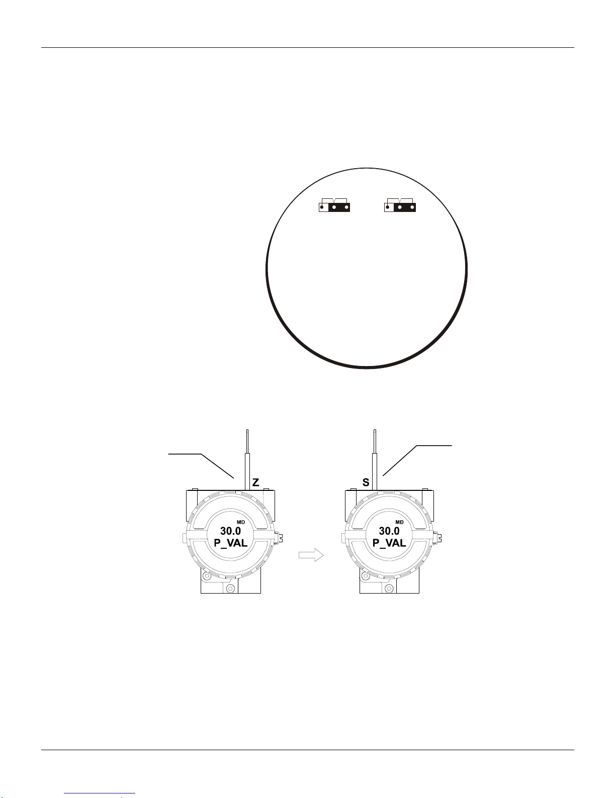
Local Programming Tree
In order to start the
local adjustment,
place the magnetic
tool in orifice Z and
wait until letters MD
are displayed.
WR
OFF
ON
J1
OFF
W1
ON
LOC
DJ
MAIN BOARD
Figure 3.19 - J1 and W1 Jumpers
Place the magnetic
tool in orifice S and
wait during 5
seconds.
3.20
Figure 3.20 - Step 1 - TT303
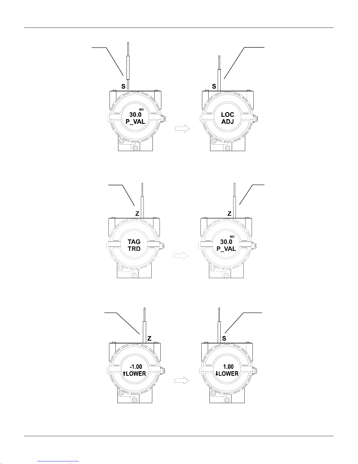
Configuration
Remove the
magnetic tool
from orifice S.
Insert the
magnetic tool in
orifice S once
more and LOC
ADJ should be
displayed.
Figure 3.21 - Step 2 - TT303
Place the magnetic tool
in orifice Z. In case this
is the first configuration,
the option shown on the
display is the TAG with
its corresponding
mnemonic configured
by the CONFIGURATION TOOL.
Otherwise, the option
shown on the display
will be the one
configured in the prior
operation. By keeping
the tool inserted in this
orifice, the local
adjustment menu will
rotate.
In this option the
first variable
(P_VAL) is
showed with its
respective value (if
you to want that it
keep static, put
the tool in S orifice
and stay there.
Figure 3.22 - Step 3 - TT303
In order to range the
lower value(lower),
simply insert the
magnetic tool in
orifice S as soon as
LOWER is shown on
the display. An arrow
pointing upward ()
increments the valve
and an arrow pointing
downward ()
decrements the
value. In order to
increment the value,
keep the tool insert in
S up to set the value
desired.
In order to decrement
the lower value, place
the magnetic tool in
orifice Z to shift the
arrow to the downward
position and then, by
inserting and keeping
the tool in orifice S, it is
possible to decrement
the lower value.
Figure 3.23 - Step 4 - TT303
3.21

TT303 – Operation and Maintenance Instruction Manual
In order to range the
upper value(upper),
simply insert the
magnetic tool in orifice
S as soon as upper is
shown on the display.
An arrow pointing
upward () increment
the value and an arrow
pointing downward ()
decrements the value.
In order to increment
the value, keep the tool
insert in S up to set the
value desired.
Figure 3.24 – Step 5 - TT303
a) In order to
change the address
value, simply take
off the magnetic
tool from orifice Z
as soon as ADDR
is shown on the
display. An arrow
pointing upward ()
increments the
address and an
arrow pointing
downward ()
decrements the
address. In order to
increment the
address, insert the
tool in S up to set
the value desired.
11
ADDR ADDR
Figure 3.25 - Step 6 - TT303
Transducer Display – Configuration
Using the Profibus View or Simatic PDM is possible to configure the Displa y Transducer block. As
the name described it is a transducer due the interfacing of its block with the LCD hardware.
The Transducer Display is treated as a normal block by any configuration tool. It means, this block
has some parameters and those ones can be configured according to customer's needs.
The customer can choose up to six parameters to be shown at LCD display; they can be parameters
just for monitoring purpose or for acting locally in the field devices by using a m agnetic tool. The
seventh parameter is used to access the physical device address. The user can change this
address according to his application. To access and configure the Display Block, please, select
"Device OnLine Configuration - Display Block", in the main menu:
In order to
decrement the
upper value, place
the magnetic tool in
orifice Z to shift the
arrow to the
downward position
an then, by
insetting and
keeping the tool in
orifice S, it is
possible to
decrement the
upper value.
In order to
decrement the
address value,
place the magnetic
tool in orifice Z to
shift the arrow to
the downward
position and then,
by inserting and
keeping the tool in
orifice S, it is
possible to
decrement the
address value.
3.22

Configuration
Display Transducer Block
The local adjustment is completely configured by Profibus View or Simatic PDM. It means, the
user can select the best options to fit his application. From factory, it is configured with the options to
set the Upper and Lower trim, for monitoring the input transducer output and check the Tag.
Normally, the transmitter is much better configured by Profibus View or Simatic PDM, but the local
functionality of the LCD permits an easy and fast ac tion on certain p arameters, since it does not rel y
on communication and network wiring connections. Among the possibilities by Local Adjustment, the
following options can be emphasized: Mode block, Outputs monitoring, Tag visualization and Tuning
Parameters setting.
Figure 3.26 – Profibus View - Display Block
Figure 3.27 – PDM Simatic - Display Block
3.23

TT303 – Operation and Maintenance Instruction Manual
The interface between the user is described very detailed on the "General Installation, Operation
and Maintenance Procedures Manual". Please take a detailed look at this manual i n the chapter
related to "Programming Using Local Adjustment". The resources on this transducer display are
very signifcant, and all of the Series 303 field devices from SMAR have the same methodology to
handle with it. So, since the user has learned once, he is capable to handle all kind of field devices
from SMAR.
All function blocks and transducers defined according Profibus PA have a description of their
features written by the Device Description Language.
This feature permits those third parties configuration tools enabled by Device Description Service
technology can interpret these features and make them accessible to configure. The Function
Blocks and Transducers of Series 303 have been defined rigorously according the Profibus PA
specifications in order to be interoperable to other parties.
In order to enable the local adjustment using the magnetic tool, it is necessary to previ ously prepar e
the parameters related with this operation via System Configuration.
There are six groups of parameters, which may be pre-co nfigured by the user in order to able, a
possible configuration by means of the local adjustment. As an example, let’s suppose that you
don’t want to show some parameters; in this case, simply select "None" in th e parameter, "Select
Block Type". Doing this, the device will not take the parameters related (indexed) to its Block as a
valid parameter.
Definition of Parameters and Values
Select Block Type
This is the type of the block where the parameter is located. The user can choose: Transducer
Block, Analog Input Block, Totalizer Block, Physical Block or None.
Select/Set Parameter Type/Index
This is the index related to the parameter to be actuated or viewed (0, 1, 2…). For each block there
are some pre-defined indexes. Refer to the Function Blocks Manual to kno w the desired indexes
and then just enter the desired index.
Set Mnemonic
This is the mnemonic for the parameter identification (it accepts a maximum of 16 ch aracters in the
alphanumeric field of the display). Choose the mnemonic, preferably with no more than 5 characters
because, this way, it will not be necessary to rotate it on the display.
Set Decimal Step
It is the increment and decrement in decimal units when the parameter is Float or Float Status
value, or integer, when the parameter is in whole units.
Set Decimal Point Place
This is the number of digits after the decimal point (0 to 3 decimal digits).
Set Access Permission
The access allows the user to read, in the case of the “Monitoring” option, and to write when
"Action" option is selected, then the display will show the increment and decrement arrows.
Set Alpha Numerical
These parameters include two options: value and mnemonic . In option va lue, it is possi ble to displ a y
data both in the alphanumeric and in the numeric fields; this way, in the case of a data higher than
10000, it will be shown in the alphanumeric field.
In the mnemonic option, the display may show the data in the numeric field and the mnemonic in the
alphanumeric field.
For devices where the software version is higher or equal to 1.10, please see the
"Programming Using Local Adjustment ", on this manual.
In case you wish to visualize a certain tag, choos e for the index relative equa l to "tag". To configur e
other parameters just select "LCD-II" up to "LCD-VI" windows:
3.24

Configuration
The option
"Write" should
be selected in
order to
execute the
upgrade of local
adjustment
programming
tree.
After its step
all the
parameters
selected will
be shown on
the LCD
display.
Figure 3.28 – Profibus View - Parameters for Local Adjustment Configuration
The window "Local Address Change" allo ws the user "enable/disable" the access to changing th e
physical device address.
Figure 3.29 – PDM Simatic - Parameters for Local Adjustment Configuration
3.25

TT303 – Operation and Maintenance Instruction Manual
When the option
“enable” is
selected, the user
can change the
physical device
address
Figure 3.30 – Profibus View - Parameters for Local Adjustment Configuration
Figure 3.31 – PDM Simatic - Parameters for Local Adjustment Configuration
When the user enter into the local adjustment and rotate the param eters using the magnetic tool,
after escaping to normal operation, e.g, the monitoring, if the parameter when the mag netic tool is
removed has "Access Permission equal to "monitoring", then this last parameter will be sho wn at the
LCD.
Always on the LCD interface will be sho wn two param eters at the sam e time, s witching bet ween t he
configured parameter at the LCD-II and the last monitoring parameter. If the user does not want to
show two parameters at the same time, it is only necessary to opt for "none" when configure the
LCD-II:
3.26
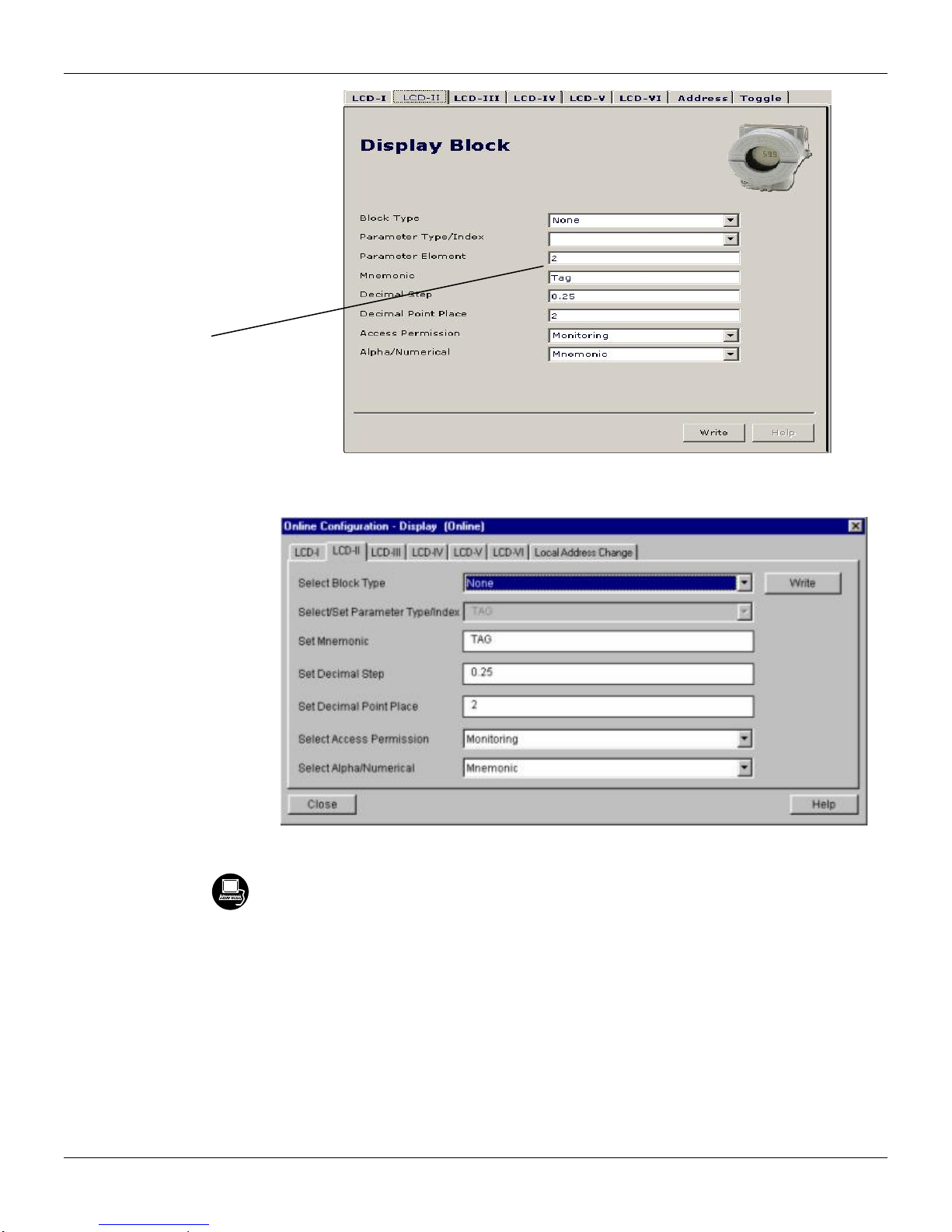
Configuration
Selecting
"None", only
the last
chosen
monitoring
parameter will
be shown at
LCD.
Figure 3.32 – Profibus View - Parameters for Local Adjustment Configuration
Figure 3.33 – PDM Simatic - Parameters for Local Adjustment Configuration
The user can select the "Mode Block" parameter at the LCD. In this case is necessary to select the
index equal to "Mode Block":
3.27

TT303 – Operation and Maintenance Instruction Manual
With this
option, the
Mode Block
parameter is
shown at the
LCD.
Figure 3.34 – Profibus View - Parameters for Local Adjustment Configuration
Figure 3.35 – PDM Simatic - Parameters for Local Adjustment Configuration
3.28

Cyclical Diagnosis
Configuration
Via cyclic communication is possible to verify diagnostics from the TT303 usin g the Profibus Master
Class 1 or even via acyclic communication via Master Class 2. T he Profibus-PA devices provi de up
to 4 standard diagnoses bytes via Physcial Block (s ee figure 3.36 and 3.37) and when the most
significant bit of the fourth Byte is "1", the diagnose will extend the information in more 6 bytes.
These Diagnosis bytes can also be monitored via cyclic tools.
Figure 3.36 – Cyclical Diagnosis
Figure 3.37 – Cyclic Diagnosis mapping for 4 bytes of Physical Block
Unit_Diag_bit is described in the GSD file Profibus-PA device.
See below a description part of a GSD file for the 4 bytes and more detail:
;----------- Description of device related diagnosis: --------------------;
Unit_Diag_Bit(16) = "Error appears"
Unit_Diag_Bit(17) = "Error disappears"
;
;Byte 01
Unit_Diag_Bit(24) = "Hardware failure electronics"
Unit_Diag_Bit(25) = "Not used 25"
Unit_Diag_Bit(26) = "Not used 26"
Unit_Diag_Bit(27) = "Electronic temperature too high"
Unit_Diag_Bit(28) = "Memory error"
Unit_Diag_Bit(29) = "Measurement failure"
Unit_Diag_Bit(30) = "Not used 30"
Unit_Diag_Bit(31) = "Not used 31"
;Byte 02
Unit_Diag_Bit(32) = "Not used 32"
Unit_Diag_Bit(33) = "Not used 33"
Unit_Diag_Bit(34) = "Configuration invalid"
3.29

TT303 – Operation and Maintenance Instruction Manual
Unit_Diag_Bit(35) = "Restart"
Unit_Diag_Bit(36) = "Coldstart"
Unit_Diag_Bit(37) = "Maintenance required"
Unit_Diag_Bit(38) = "Not used 38"
Unit_Diag_Bit(39) = "Ident_Number violation"
;Byte 03
Unit_Diag_Bit(40) = "Not used 40"
Unit_Diag_Bit(41) = "Not used 41"
Unit_Diag_Bit(42) = "Not used 42"
Unit_Diag_Bit(43) = "Not used 43"
Unit_Diag_Bit(44) = "Not used 44"
Unit_Diag_Bit(45) = "Not used 45"
Unit_Diag_Bit(46) = "Not used 46"
Unit_Diag_Bit(47) = "Not used 47"
;byte 04
Unit_Diag_Bit(48) = "Not used 48"
Unit_Diag_Bit(49) = "Not used 49"
Unit_Diag_Bit(50) = "Not used 50"
Unit_Diag_Bit(51) = "Not used 51"
Unit_Diag_Bit(52) = "Not used 52"
Unit_Diag_Bit(53) = "Not used 53"
Unit_Diag_Bit(54) = "Not used 54"
Unit_Diag_Bit(55) = "Extension Available"
;Byte 05 TRD 01 Block & PHY Block
Unit_Diag_Bit(56) = "Sensor failure"
Unit_Diag_Bit(57) = "Secondary Value (body device temperature) is in failure"
Unit_Diag_Bit(58) = "Primary Value Type is Backup-sensor and the Backup-Sensor is active"
Unit_Diag_Bit(59) = "Not used 59"
Unit_Diag_Bit(60) = "Not used 60"
Unit_Diag_Bit(61) = "Not used 61"
Unit_Diag_Bit(62) = "Calibration Error - Check XD_ERROR parameter for TRD 1 or TRD 2"
Unit_Diag_Bit(63) = "Device is writing lock"
;byte 06 AI_1 Block
Unit_Diag_Bit(64) = "Simulation Active in AI 1 Block"
Unit_Diag_Bit(65) = "Fail Safe Active in AI 1 Block"
Unit_Diag_Bit(66) = "AI 1 Block in Out of Service"
Unit_Diag_Bit(67) = "AI 1 Block Output out of High limit"
Unit_Diag_Bit(68) = "AI 1 Block Output out of Low limit"
Unit_Diag_Bit(69) = "Not used 69"
Unit_Diag_Bit(70) = "Not used 70"
Unit_Diag_Bit(71) = "Not used 71"
;byte 07 AI_2 Block
Unit_Diag_Bit(72) = "Simulation Active in AI 2 Block"
Unit_Diag_Bit(73) = "Fail Safe Active in AI 2 Block"
Unit_Diag_Bit(74) = "AI 2 Block in Out of Service"
Unit_Diag_Bit(75) = "AI 2 Block Output out of High limit"
Unit_Diag_Bit(76) = "AI 2 Block Output out of Low limit"
Unit_Diag_Bit(77) = "Not used 77"
Unit_Diag_Bit(78) = "Not used 78"
Unit_Diag_Bit(79) = "Not used 79"
;byte 08
Unit_Diag_Bit(80) = "Sensor 1 Failure"
Unit_Diag_Bit(81) = "Sensor 2 Failure"
Unit_Diag_Bit(82) = "Sensor 1 failed and PV comes from Sensor 2"
Unit_Diag_Bit(83) = "Not used 83"
Unit_Diag_Bit(84) = "Not used 84"
Unit_Diag_Bit(85) = "Not used 85"
3.30

Configuration
Unit_Diag_Bit(86) = "Not used 86"
Unit_Diag_Bit(87) = "Not used 87"
;byte 09
Unit_Diag_Bit(88) = "Not used 88"
Unit_Diag_Bit(89) = "Not used 89"
Unit_Diag_Bit(90) = "Not used 90"
Unit_Diag_Bit(91) = "Not used 91"
Unit_Diag_Bit(92) = "Not used 92"
Unit_Diag_Bit(93) = "Not used 93"
Unit_Diag_Bit(94) = "Not used 94"
Unit_Diag_Bit(95) = "Not used 95"
;byte 10
Unit_Diag_Bit(96) = "Not used 96"
Unit_Diag_Bit(97) = "Not used 97"
Unit_Diag_Bit(98) = "Not used 98"
Unit_Diag_Bit(99) = "Not used 99"
Unit_Diag_Bit(100) = "Not used 100"
Unit_Diag_Bit(101) = "Not used 101"
Unit_Diag_Bit(102) = "Not used 102"
Unit_Diag_Bit(103) = "Not used 103"
NOTE
If the FIX flag is active on LCD, the TT303 is configured to "Profile Specific" mode. When in "Manufacturer
Specific" mode, the Identifier Number is 0x089A. Once the Identifier_Number_Selector is changed from "Profile
Specific" to "Manufacturer Specific" or vice-versa, one must wait 5 seconds while is saved. Then, turn the
TT303 off and turn it on again. So, the Identifier Number is updated to the communication level. If the
equipment is in "Profile Specific" and using the GSD file Identifier Number equals 0x089A, the acyclic
communication will work with the tools based on EDDL, FDT/DTM, but no cyclic communication with the
Profibus-DP master.
3.31

TT303 – Operation and Maintenance Instruction Manual
3.32

Section 4
SYMPTOM
PROBABLE SOURCE OF PROBLEM
NO COMMUNICATION
Transmitter Connections
Check wiring polarity and continuity.
Check for shorts or ground loops.
Check if the power supply connector is connected to main board.
Check if the shield is not used as a conductor.
It should be grounded at one end only.
Power Supply
Check power supply output. The voltage must be between 9 - 32 VDC at the TT303 terminals.
Noise and ripple should be within the following limits:
a) 16 mV peak to peak from 7.8 to 39 KHz.
b) 2 V peak to peak from 47 to 63 Hz for non-intrinsic safety applications and 0.2 V for intrinsic
safety applications.
c) 1.6 V peak to peak from 3.9 MHz to 125 MHz.
Network Connection
Check that the topology is correct and all devices are connected in parallel.
Check that two Terminators are OK and correctly positioned.
Check that the coupler connections are OK and correctly positioned.
Check that the Terminators are according to the specifications.
Check length of trunk and spurs.
Check spacing between couplers.
Network Configuration
Make sure that device address is configured correctly.
Electronic Circuit Failure
Check the main board for defect by replacing it with a spare one.
INCORRECT READING
Transmitter Connections
Check for intermittent short circuits, open circuits and grounding problems.
Check if the sensor is correctly connected to the TT303 terminal block.
Check if the sensor signal is reaching the TT303 terminal block by measuring it with a multimeter
at the transmitter- end. For mV and thermocouples test can be done with connected and
disconnected to the transmitter.
Noise, Oscillation
Adjust damping
Check grounding of the transmitters housing, extra important for mV and thermocouple input.
Check the terminal block for moisture.
Check that the shielding of the wires between sensor/transmitter and transmitter/panel is grounded
only in one end.
Sensor
Check the sensor operation; it shall be within its characteristics.
Check sensor type; it shall be the type and standard that the TT303 has been configured to.
Check if process is within the range of the sensor and the TT303.
INCORRECT READING
Electronic Circuit Failure
Check the integrity of circuit replacing it with a spare one.
Transmitter Configuration
Check if the sensor and wires configuration are correct.
Troubleshooting
MAINTENANCE PROCEDURES
SMAR TT303 transmitters are extensively tested and inspected before delivery to the end user.
Nevertheless, during their design and development, consideration was given to the possibility of
repairs being made by the end user, if necessary.
In general, it is recommended that end users do not try to repair printed circuit boards. Spare circuit
boards may be ordered from SMAR whenever necessary.
Table 4.1 - Messages of Errors and Potential Cause
4.1

TT303 - Operation and Maintenance Instruction Manual
WARNING
The boards have CMOS components, which may be damaged by electrostatic discharges.
Observe correct procedures for handling CMOS components. It is also recommended to store the
circuit boards in electrostatic-proof cases.
Disassembly Procedure
Refer to Figure 4.2. Make sure to disconnect the power supply before disassembling the transmitter.
Sensor
If the sensor is mounted on the transmitter, first disconnect the wires in order to prevent the wires
from breaking. To access the terminal block, first loosen the cover locking screw on the side marked
“Field Terminals”, then unscrew the cover.
Electronic Circuits
The main board (5) and input board (7) are matched pairs and must be changed together and not
mixed with others. To remove the circuit boards (5 and 7) and display (4), first loosen the cover
locking (8) on the side not marked “Field Terminals” then unscrew the cover (1).
Loosen the two screws (3) that anchors the display and the main circuit board. Gently pull out the
display, and then the main board (5). To remove the input board (7), first unscrew the two screws (6)
that anchors it to the housing (9), gently pull out the board.
Reassemble Procedure
Put input board (7) into housing (9).
Anchor input board with its screws (6).
Put main board (5) into the housing, ensuring all inter connecting pins are connected.
Put display (4) into the housing, observing the four mounting positions (See Figure 4.1 -
Four Possible Positions of the Display) “_” should point in the direction desired as UP.
Anchors main board and display with their screws (3).
Fit the cover (1) and lock it using the locking screw (8).
Figure 4.1 - Four Possible Positions of the Display
Interchangeability
The Main and Input boards must be kept together because of the calibration data that is stored in
the main board EEPROM. In the case of one board being faulty, both must be replaced.
4.2
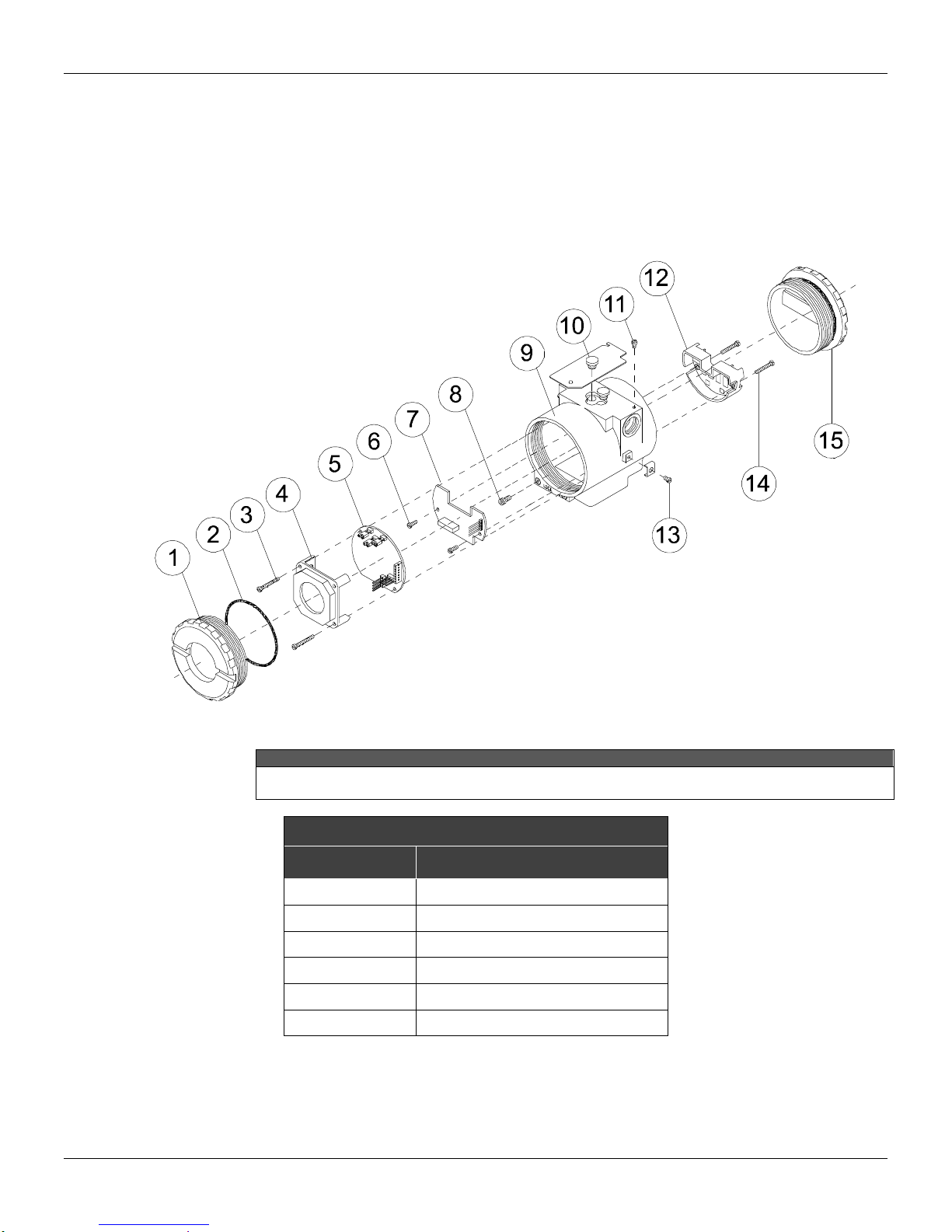
NOTE
For aluminium housing there is an insert in the position 13. This insert is used to improve the
grounding.
ACCESSORIES
ORDERING
CODE
DESCRIPTION
SD1
Magnetic Tool for Local Adjustment
PS302
Power Supply
BT302
Terminator
FDI302
Field Device Interface
DF47
Intrinsic Safety Barrier
DF48
Fieldbus Repeater
Returning Materials
Maintenance Procedures
Should it become necessary to return the transmitter to SMAR, simply contact your local agent or
SMAR office, informing the defective instrument’s serial number, and return it to our factory.
In order to expedite analysis and solution of the problem, the defective item should be returned with
a description of the failure observed, with as many details as possible. Other information concerning
the instruments operation, such as service and process conditions are also helpful.
Figure 4.2 - Exploded View
Table 4.2 - Accessories
4.3

TT303 - Operation and Maintenance Instruction Manual
SPARE PARTS LIST
DESCRIPTION OF PARTS
POSITION
CODE
CATEGORY
(NOTE 1)
HOUSING, Aluminum (NOTE 2)
. ½ - 14 NPT
9
400-0298
. M20 x 1.5
9
400-0299
. PG 13.5 DIN
9
400-0300
HOUSING, 316 SS (NOTE 2)
. ½ - 14 NPT
9
400-0301
. M20 x 1.5
9
400-0302
. PG 13.5 DIN
9
400-0303
COVER (INCLUDES O'RING)
. Aluminum
1 and 15
204-0102
. 316 SS
1 and 15
204-0105
COVER WITH WINDOW FOR INDICATION (INCLUDES O’RING)
. Aluminum
1
204-0103
. 316 SS
1
204-0106
COVER LOCKING SCREW
8
204-0120
EXTERNAL GROUND SCREW
13
204-0124
IDENTIFICATION PLATE FIXING SCREW
11
204-0116
DIGITAL INDICATOR
4
214-0108
TERMINAL INSULATOR
12
314-0123
MAIN INPUT CIRCUIT BOARD ASSEMBLY
5 and 7
400-0304
A
O’RINGS (NOTE 3)
. Cover, Buna-N
2
204-0122
B
TERMINAL HOLDING SCREW.
. Housing in Aluminum
14
304-0119
. Housing in 316 Stainless Steel
14
204-0119
MAIN BOARD SCREW HOUSING IN ALUMINUM
. Units with indicator
3
304-0118
. Units without indicator
3
304-0117
MAIN BOARD SCREW HOUSING IN 316 STAINLESS STEEL
. Units with indicator
3
204-0118
. Units without indicator
3
204-0117
INPUT BOARD SCREW
. Housing in Aluminum
6
314-0125
. Housing in 316 Stainless Steel
6
214-0125
MOUNTING BRACKET FOR 2” PIPE MOUNTING (NOTE 4)
. Carbon Steel
-
214-0801
. Stainless Steel 316
-
214-0802
. Carbon Steel bolts, nuts, washers and U-clamp in Stainless Steel
-
214-0803
LOCAL ADJUSTMENT PROTECTION CAP
10
204-0114
4.4
Table 4.3 - Spare Part List

Maintenance Procedures
NOTE
1. For category A, it is recommended keep, in stock, 25 parts installed for each set, and for category B, 50.
2. It includes Terminal holder insulator, bolts (cover lock, grounding and terminal holder insulator) and identification plate without
certification.
3. 0-Rings are packaged in packs of 12 units. Including U-clamp, nuts, bolts and washers.
4.5

TT303 - Operation and Maintenance Instruction Manual
4.6

Section 5
Functional Specifications
Inputs
See table 5.1, 5.2, 5.3 and 5.4
Output and
Communication
Protoco
Digital only. Complies with IEC 61158-2: 2000 (H1): 31.25 kbit/s voltage mode, bus powered.
Power Supply /
Current
Consumption
Bus powered: 9 - 32 Vdc.
Quiescent current consumption: 12 mA.
Indicator
4 1/2 -digit numerical and 5-character alphanumerical LCD indicator (optional).
Hazardous Area
Certifications
Intrinsic Safety (FM, CSA, NEMKO, EXAM, CEPEL, NEPSI), Explosion Proof (FM, CSA, NEMKO, CEPEL), Dust Ignition
Proof (FM), Non-incendive (FM), FISCO (FM, CSA, NEMKO, EXAM, CEPEL, NEPSI) and FNICO (FM, CSA, NEMKO,
EXAM, CEPEL)
European Directive
Information
Authorized representative in European Community
Smar Gmbh-Rheingaustrasse 9-55545 Bad Kreuzanach
ATEX Directive (94/9/EC) – Equipment and protective systems intended for use in potentially explosive
atmospheres
This product was certified according European Standards at NEMKO and EXAM (former DMT). The certified body for
manufacturing quality assessment is EXAM (number 0158).
LVD Directive 2006/95/EC – Electrical Equipment designed for use within certain voltage limits
According the LVD directive Annex II the equipment under ATEX “Electrical equipment for use in an explosive
atmosphere” directive are excluded from scope from this directive.
Zero and Span
Adjustments
No interactive, via digital communication.
Failure Alarm
(Diagnostics)
For sensor or circuit failures, status is sent to output parameters. Detailed diagnostics are available in the contained
parameters.
Temperature
Limits
Ambient:
Storage:
Display:
-40 ºC to 85 ºC
-40 ºC to 120 ºC
-20 ºC to 80 ºC
-40 ºC to 85 ºC
(-40 ºF to 185 ºF)
(-40 ºF to 248 ºF)
(-4 ºF to 176 ºF)
(-40 ºF to 185 ºF)
(Without damage)
Turn-on Time
Performs within specifications in less than 10 seconds after power is applied to the transmitter.
Configuration
Basic configuration may be done using the local adjustment magnetic tool if device is fitted with display. Complete
configuration is possible using configuration tools such as Syscon302 (System Configuration Tool), AMSTM, FieldCareTM
and HHT375. TT303 can be configured using Profibus View or Simatic PDM.
Humidity Limits
0 to 100% RH
Damping
Adjustment
User configurable from 0 to 32 seconds (via digital communication).
Performance Specifications
Accuracy
See tables 1, 2 and 3
Temperature
Effect
For a 10 ºC variation:
mV (-6 to 22 mV), TC (NBS: B, R, S,T): ± 0.03% of the input milivoltage or 0.002 mV whichever is greater;
mV (-10 to 100 mV), TC (NBS: E, J, K, N; DIN: L, U): ± 0.03% of the input milivoltage or 0.01 mV whichever is greater;
mV (-50 to 500 mV): ± 0.03% of the input milivoltage or 0.05 mV whichever is greater;
Ohms (0 to 100Ω), RTD (GE: Cu10): ± 0.03% of the input resistence or 0.01Ω whichever is greater;
Ohms (0 to 400Ω), RTD (DIN: Ni120; IEC: Pt50, Pt100; JIS: Pt50, Pt100): ± 0.03% of the input resistence or 0.04Ω
whichever is greater;
Ohms (0 to 2000Ω), RTD (IEC: Pt500): ± 0.03% of the input resistence or 0.2Ω whichever is greater;
TC: cold-junction compensation rejection 60:1 (Reference: 25.0 ± 0.3 °C).
Power Supply
Effect
± 0.005% of calibrated span per volt
Electrical
Connection
1/2 - 14 NPT
M20 X 1.5
PG 13.5 DIN
1/2 - 14 NPT X 3/4 NPT (AI 316) - with adapter
1/2 - 14 NPT X 3/4 BSP (AI 316) - with adapter
1/2 - 14 NPT X 1/2 BSP (AI 316) - with adapter
Note: Explosion proof approvals do not apply to adapter,
only to transmitter.
Mounting
Can be attached directly to the sensor. With an optional bracket can be installed on a 2" pipe or fixed on a wall or panel.
Physical Specifications
Approximate
Weights
Sem display e braçadeira de montagem: 0,80 kg
Somar para o display: 0,13 kg
Somar para a braçadeira de montagem: 0,60 kg
TECHNICAL CHARACTERISTIC
5.1

TT303 – Operation and Maintenance Instruction Manual
Physical Specifications
Control
Functions
Characteristics
(Optional)
PHY, TRD, DSP e AI
2, 3 or 4 wires
SENSOR
TYPE
RANGE °C
RANGE °F
MINIMUM
SPAN °C
°C DIGITAL
ACCURACY*
RTD
Cu10
GE
-20
to
250
-4
to
482
50
± 1.0
Ni120
DIN
-50
to
270
-58
to
518 5
± 0.1
Pt50
IEC
-200
to
850
-328
to
1562
10
± 0.25
Pt100
IEC
-200
to
850
-328
to
1562
10
± 0.2
Pt500
IEC
-200
to
450
-328
to
842
10
± 0.2
Pt1000
IEC
-200
to
300
-328
to
572
10
± 0.2
Pt50
JIS
-200
to
600
-328
to
1112
10
± 0.25
Pt100
JIS
-200
to
600
-328
to
1112
10
± 0.25
THERMOCOUPLE
B
NBS
100
to
1800
212
to
3272
50
± 0.5**
E
NBS
-100
to
1000
-148
to
1832
20
± 0.2
J
NBS
-150
to
750
-238
to
1382
30
± 0.3 K NBS
-200
to
1350
-328
to
2462
60
± 0.6
N
NBS
-100
to
1300
-148
to
2372
50
± 0.5
R
NBS 0 to
1750
32
to
3182
40
± 0.4 S NBS 0 to
1750
32
to
3182
40
± 0.4
T
NBS
-200
to
400
-328
to
752
15
± 0.15
L
DIN
-200
to
900
-328
to
1652
35
± 0.35
U
DIN
-200
to
600
-328
to
1112
50
± 0.5
Table 5.1 - 2, 3 or 4 wires Sensor Characteristics
* Accuracy of value read on display and accessed by communication. The 4-20 mA accuracy is the digital accuracy ±0.03%
** Not applicable for the first 20% of the range (up to 440 °C).
5.2

Technical Characteristics
DIFFERENTIAL
SENSOR
TYPE
RANGE °C
RANGE °F
MINIMUM
SPAN °C
°C DIGITAL
ACCURACY*
RTD
Cu10
GE
-270
to
270
-486
to
486
50
± 2.0
Ni120
DIN
-320
to
320
-576
to
576 5
± 0.5
Pt50
IEC
-1050
to
1050
-1890
to
1890
10
± 1.0
Pt100
IEC
-1050
to
1050
-1890
to
1890
10
± 1.0
Pt500
IEC
NA
NA
NA
NA
Pt1000
IEC
NA
NA
NA
NA
Pt50
JIS
-800
to
800
-1440
to
1440
10
± 1.0
Pt100
JIS
-800
to
800
-1440
to
1440
10
± 1.5
THERMOCOUPLE
B
NBS
-1700
to
1700
-3060
to
3060
60
± 1.0**
E
NBS
-1100
to
1100
-1980
to
1980
20
± 1.0
J
NBS
-900
to
900
-1620
to
1620
30
± 0.6 K NBS
-1550
to
1550
-2790
to
2790
60
± 1.2
N
NBS
-1400
to
1400
-2520
to
2520
50
± 1.0
R
NBS
-1750
to
1750
-3150
to
3150
40
± 2.0 S NBS
-1750
to
1750
-3150
to
3150
40
± 2.0
T
NBS
-600
to
600
-1080
to
1080
15
± 0.8
L
DIN
-1100
to
1100
-1980
to
1980
35
± 0.7 U DIN
-800
to
800
-1440
to
1440
50
± 2.5
SENSOR
RANGE
mV
MINIMUM
SPAN mV
*DIGITAL
ACCURACY %
SENSOR
RANGE
Ohm
MINIMUM
SPAN Ohm
*DIGITAL
ACCURACY %
mV
-6 to 22
0.40
± 0.02% or ± 2 µV
Ohm
0 or 100
1
± 0.02% or ± 0.01 Ohm
-10 to 100
2.00
± 0.02% or ± 10 µV
0 or 400
4
± 0.02% or ± 0.04 Ohm
-50 to 500
10.00
± 0.02% or ± 50 µV
0 or 2000
20
± 0.02% or ± 0.20 Ohm
mV DIF.
-28 to 28
0.40
± 0.10% or ± 10 µV
Ohm DIF.
-100 or 100
1
± 0.08% or ± 0.04 Ohm
-110 to 110
2.00
± 0.10% or ± 50 µV
-400 or 400
4
± 0.1% or ± 0.20 Ohm
Table 5.2 - Differential Sensor Characteristics
* Accuracy of value read on display and accessed by communication.
** Not applicable for the first 20% of the range (up to 440 °C).
Table 5.3 - mV Sensor Characteristics Table 5.4 - Ohm Sensor Characteristics
* Accuracy of value read on display and accessed by communication. The 4-20 mA accuracy is the digital accuracy ±0.03%
** Not applicable for the first 20% of the range (up to 440 °C).
NA Not applicable.
5.3

TT303 – Operation and Maintenance Instruction Manual
MODEL
TEMPERATURE TRANSMITTER
COD.
Local Indicator
0
Without Indicator
1
With Digital Indicator
COD.
Mounting Bracket
0
1
Without Bracket
Carbon Steel Bracket
2
7
316 SST Bracket
Carbon Steel Bracket with 316 SST Fasteners
A
Flat, 304 SST bracket and 316 SST accessories
COD.
Electrical Connections
0
1
2
1/2 - 14 NPT (3)
1/2 - 14 NPT X 3/4 NPT (316 SST) - With adapter (4)
1/2 - 14 NPT X 3/4 BSP (316 SST) - With adapter (2)
3
A
B
1/2 - 14 NPT X 1/2 BSP (316 SST) - With adapter (2)
M20 x 1.5 (5)
Pg 13.5 DIN (6)
Z
According to user´s notes
COD.
Housing Material (8) (9)
H0
H1
H2
Aluminum (IP/TYPE)
316 SST (IP/TYPE)
Aluminum for saline atmosphere (IPW/TYPEX) (10)
H3
H4
316 SST for saline atmosphere (IPW/TYPEX) (10)
Copper Free Alunimium for saline atmosphere (IPW/TYPEX) (10)
COD.
Identification Plate
I1
I3
FM: XP, IS, NI, DI
CSA: XP, IS, NI, DI
I4
I5
EXAM (DMT): Ex-ia; NEMKO: Ex-d
CEPEL: Ex-d, Ex-ia
I6
I7
Without Certification
EXAM (DMT): Group I, M1 Ex-ia
IE
NEPSI: Ex-ia
COD.
Tag Plate (7)
J0
J1
With tag, when specified (Default)
Blank
J2
According to user's notes
COD.
Sensor Connection
L2
L3
L4
2-wire
3-wire
4-wire
LF
LD
LB
Differential
Double 2-wire
Backup
COD.
P0
P3
P4
Gray Munsell N 6,5 Polyester (Default)
Black Polyester
White Epoxy
P5
P8
P9
Yellow Polyester
Without Painting
Safety Blue Epoxy – Electrostatic Painting
PC
Safety Blue Polyester Electrostatic Painting
COD.
Sensor Type
T1
T2
T3
T4
T5
T6
T7
T8
T9
Cu10 - GE
Ni120 - DIN
PT50 - IEC
PT100 - IEC
PT500 - IEC
PT50 - JIS
PT100 - JIS
2K OHM
400 OHM
TA
TB
TC
TD
TE
TF
TG
TH
TK
Thermocouple type B - NBS
Thermocouple type E - NBS
Thermocouple type J - NBS
Thermocouple type K - NBS
Thermocouple type N - NBS
Thermocouple type R - NBS
Thermocouple type S - NBS
Thermocouple type T - NBS
Thermocouple type L - DIN
TP
TN
TO
TQ
TR
TS
TT
TU
Thermocouple type U - DIN
100 OHM
Special OHM
22 mV
100 mV
500 mV
Special Mv
RTD PT1000 – IEC
TT303 1 2 0 H1
I1
JO
L2
P8
T1
NOTE
(1) Values limited to 4 1/2 digits; units limited to 5 characters.
(2) Explosion proof approvals do not apply to adapter, only to transmitter.
(3) Certified for use in hazardous locations (CEPEL, CSA, FM, NEPSI, NEMKO, EXAM).
(4) Certified for use in hazardous locations (CEPEL, CSA, FM).
(5) Certified for use in hazardous locations (CEPEL, FM, NEPSI, NEMKO, EXAM).
(6) Certified for use in hazardous locations (CEPEL, NEPSI, NEMKO, EXAM).
(7) Rectangular plate in 316 SST.
(8) IPX8 tested in 10 meters of water column for 24 hours.
(9) Ingress Protection:
Product
CEPEL
NEMKO / EXAM
FM
CSA
NEPSI
TT300
IP66/68W
IP66/68W
Type 4X/6(6P)
Type 4X
IP67
(10) IPW/TYPE testes for 200 hours according to NBR 8094 / ASTM B 117 standard.
Ordering Code
5.4

Crrgpfkz"C"
"
CERTIFICATIONS INFORMATION
Gwtqrgcp"Fktgevkxg"Kphqtocvkqp"
Consult www.smar.com for the EC declarations of conformity for all applicable European directives
and certificates.
ATEX Directive (94/9/EC) – “Electrical equipment and protective system intended for use in
potential explosive atmospheres”
The EC-Type Examination Certificate had been released by Nemko AS (CE0470) and/or DEKRA
EXAM GmbH (CE0158), according to European Standards.
The certification body for Production Quality Assurance Notification (QAN) and IECEx Quality
Assessment Report (QAR) is Nemko AS (CE0470).
LVD Directive 2006/95/EC – “Electrical Equipment designed for use within certain voltage
limits”
According the LVD directive Annex II, electrical equipment for use in an explosive atmosphere is
outside the scope of this directive.
According to IEC standard: IEC 61010-1:2010 - Safety requirements for electrical equipment for
measurement, control, and laboratory use - Part 1: General requirements.
"
EMC Directive 2004/108/EC - “Electromagnetic Compatibility”
The equipment is in compliance with the directive and EMC test was performed according to IEC
standards: IEC61326-1:2005 and IEC61326-2-3:2006.
To comply with the EMC directive the installation must follow these special conditions:
Use shielded, twisted-pair cable for powering the instrument and signal wiring.
Keep the shield insulated at the instrument side, connecting the other one to the ground.
Jc|ctfqwu"Nqecvkqpu"Igpgtcn"Kphqtocvkqp"
Ex Standards:
IEC 60079-0 General Requirements
IEC 60079-1 Flameproof Enclosures “d”
IEC 60079-11 Intrinsic Safety “i”
IEC 60079-26 Equipment with equipment protection level (EPL) Ga
IEC 60529 Classification of degrees of protection provided by enclosures (IP Code)
Customer responsibility:
IEC 60079-10 Classification of Hazardous Areas
IEC 60079-14 Electrical installation design, selection and erection
IEC 60079-17 Electrical Installations, Inspections and Maintenance
Warning:
Explosions could result in death or serious injury, besides financial damage.
Installation of this instrument in an explosive environment must be in accordance with the national
standards and according to the local environmental protection method. Before proceeding with the
installation match the certificate parameters according to the environmental classification.
General Notes:
Maintenance and Repair
The instrument modification or replaced parts supplied by any other supplier than authorized
representative of Smar Equipamentos Industriais Ltda is prohibited and will void the Certification.
Marking Label
Once a device labeled with multiple approval types is installed, do not reinstall it using any other
approval types. Scratch off or mark unused approval types on the approval label.
C03"

VV525"⁄"Qrgtcvkqp"cpf"Ockpvgpcpeg"Kpuvtwevkqp"Ocpwcn""
"
For Ex-i protection application
- Connect the instrument to a proper intrinsically safe barrier.
- Check the intrinsically safe parameters involving the barrier, equipment including the cable and
connections.
- Associated apparatus ground bus shall be insulated from panels and mounting enclosures.
- When using shielded cable, isolate the not grounded cable end.
- Cable capacitance and inductance plus C
Apparatus.
For Ex-d protection application
- Only use Explosion Proof/Flameproof certified Plugs, Adapters and Cable glands.
- In an Explosion-Proof/Flame-Proof installation, do not remove the instrument housing covers when
powered on.
- Electrical Connection
In Explosion-Proof installations the cable entries must be connected through conduit with sealed
unit or closed using metal cable gland or closed using metal blanking plug, all with at least IP66
and Ex-d certification. For enclosure with saline environment protection (W) and ingress protection
(IP) applications, all NPT thread parts must apply a proper water-proof sealant (a non-hardening
silicone group sealant is recommended).
For Ex-d and Ex-i protection application
- The transmitter has a double protection. In this case the transmitter shall be fitted with appropriate
certified cable entries Ex-d and the electric circuit supplied by a certified diode safety barrier as
specified for the protection Ex-ia.
Environmental Protection
- Enclosure Types (Type X): Supplementary letter X meaning special condition defined as default by
Smar the following: Saline Environment approved - salt spray exposed for 200 hours at 35ºC. (Ref:
NEMA 250).
- Ingress protection (IP W): Supplementary letter W meaning special condition defined as default by
Smar the following: Saline Environment approved - salt spray exposed for 200 hours at 35ºC. (Ref:
IEC60529).
- Ingress protection (IP x8): Second numeral meaning continuous immersion in water under special
condition defined as default by Smar the following: 1 Bar pressure during 24hours. (Ref: IEC60529).
and Li must be smaller than Co and Lo of the Associated
i
Jc|ctfqwu"Nqecvkqpu"Crrtqxcnu"
CSA (Canadian Standards Association)
Class 2258 02 – Process Control Equipment – For Hazardous Locations (CSA1110996)
Class I, Division 1, Groups B, C and D
Class II, Division 1, Groups E, F and G
Class III, Division 1
Class I, Division 2, Groups A, B, C and D
Class II, Division 2, Groups E, F and G
Class III
Class 2258 03 – Process Control Equipment – Intrinsically Safe and Non-Incendive Systems – For Hazardous Locations
(CSA 1110996)
Class I, Division 2, Groups A, B, C and D
Model TT303 Series Temperature Transmitters, supply 12-42V dc, 4-20mA; Enclosure Type 4/4X; non-incendive with
Fieldbus/FNICO Entity parameters at terminals "+"and "-" of:
Vmax =24V, Imax =570 mA, Pmax = 9,98 W, Ci = 5 nF, Li = 0;
having output terminals (“1, 2, 3 & 4") with output Entity parameters of:
Voc = 8.25V, Isc = 85.6 mA, Ca = 5.5 uF, La = 4,8 mH;
when connected as per Smar Installation drawing 102A0553; T Code T3C @ Max Ambient 40 Deg C.
Class 2258 04 – Process Control Equipment – Intrinsically Safe Entity – For Hazardous Locations (CSA1110996)
Ex ia - Class I, Division 1, Groups A, B, C and D
Ex ia - Class II, Division 1, Groups E, F and G
Ex ia - Class III, Division 1
Model TT303 Series Temperature Transmitters, supply 12-42V dc, 4-20mA; Enclosure Type 4/4X; intrinsically safe with
Fieldbus/FISCO Entity parameters at terminals "+"and "-" of:
C04"

Egtvkhkecvkqpu"Kphqtocvkqp"
Vmax =24V, Imax =380 mA, Pmax = 5.32 W, Ci = 5 nF, Li = 0;
having output terminals (A1, 2, 3 & 4") with entity parameters of:
Voc = 8.25V, Isc = 85.6 mA, Ca = 5.5 uF, La = 4,8 mH;
when connected as per SMAR Installation drawing 102A0553; T Code T3C @ Max Ambient 40 Deg C.
Note: Only models with stainless steel external fittings are Certified as Type 4X.
Special conditions for safe use:
Temperature Class T3C
Maximum Ambient Temperature: 40ºC (-20 to 40 ºC)
FM Approvals (Factory Mutual)
Intrinsic Safety (FM 3006959)
IS Class I, Division 1, Groups A, B, C and D
IS Class II, Division 1, Groups E, F and G
IS Class III, Division 1
Explosion Proof (FM 3006959)
XP Class I, Division 1, Groups A, B, C and D
Dust Ignition Proof (FM 4Y3A4.AX)
DIP Class II, Division 1, Groups E, F and G
DIP Class III, Division 1
Non Incendive (FM 3006959)
NI Class I, Division 2, Groups A, B, C and D
Environmental Protection (FM 3006959)
Option: Type 4X/6/6P or Type 4/6/6P
Special conditions for safe use:
Entity Parameters Fieldbus Power Supply Input (report 3015629):
Vmax = 24 Vdc, Imax = 250 mA, Pi = 1.2 W, Ci = 5 nF, Li = 12 uH
Vmax = 16 Vdc, Imax = 250 mA, Pi = 2 W, Ci = 5 nF, Li = 12 uH
Temperature Class: T4
Maximum Ambient Temperature: 60ºC (-20 to 60 ºC)
NEMKO (Norges Elektriske MaterielKontroll)
Explosion Proof (NEMKO 13 ATEX 1570X)
Group II, Category 2 G, Ex d, Group IIC, Temperature Class T6, EPL Gb
Ambient Temperature: -20 ºC to +60 ºC
Environmental Protection (NEMKO 03ATEX1570X)
Options: IP66/68W or IP66/68
Special conditions for safe use:
Repairs of the flameproof joints must be made in compliance with the structural specifications provided by the manufacturer.
Repairs must not be made on the basis of values specified in tables 1 and 2 of EN/IEC 60079-1.
The Essential Health and Safety Requirements are assured by compliance with:
EN 60079-0:2012 General Requirements
EN 60079-1:2007 Flameproof Enclosures “d”
EXAM (BBG Prüf - und Zertifizier GmbH)
Intrinsic Safety (DMT 00ATEX E 061)
Group I, Category M2, Ex ia, Group I, EPL Mb
Group II, Category 2 G, Ex ia, Group IIC, Temperature Class T4/T5/T6, EPL Gb
Supply circuit for the connection to an intrinsically safe FISCO fieldbus-circuit:
Ui = 24 Vdc, Ii = 380 mA, Pi = 5.32 W, Ci ≤ 5 nF, Li = Neg
Parameters of the supply circuit comply with FISCO model according to Annex G EN60079-11:2012, replacing EN 6007927:2008.
"
C05"

VV525"⁄"Qrgtcvkqp"cpf"Ockpvgpcpeg"Kpuvtwevkqp"Ocpwcn""
"
2 wire/3 wire/4 wire measuring circuit in type of protection Ex ia I / II C for the connection to intrinsically safe thermocouples or
resistance temperature indicators:
Uo = 6.5 Vdc, Io = 20 mA, Po = 30 mW, Ci ≤ 300 nF, Li = Neg, Co ≤ 700 nF, Li ≤ 20 mH
The 2 wire/3 wire/4 wire measuring circuit is galvanically separated from the fieldbus circuit.
Ambient Temperature: -40ºC ≤ Ta ≤ +60ºC
The Essential Health and Safety Requirements are assured by compliance with:
EN 60079-0:2012 + A11:2013 General Requirements
EN 60079-11:2012 Intrinsic Safety “i”
CEPEL (Centro de Pesquisa de Energia Elétrica)
Intrinsic Safety (CEPEL 96.0076X)
Ex ia, Group IIC, Temperature Class T4/T5, EPL Ga
Entity Parameters:
Pi = 5.32W, Ui = 30V, Ii = 380mA, Ci = 5,0nF, Li = Neg
Ambient Temperature:
-20 to 65 ºC for T4
-20 to 50 ºC for T5
Explosion Proof (CEPEL 97.0089)
Ex d, Group IIC, Temperature Class T6, EPL Gb
Maximum Ambient Temperature: 40ºC (-20 to 40 ºC)
Environmental Protection (CEPEL 96.0076X AND CEPEL 97.0089)
Options: IP66/68W or IP66/68
Special conditions for safe use:
The certificate number ends with the letter "X" to indicate that for the version of Temperature Transmitter model TT303 equipped
with housing made of aluminum alloy, only can be installed in "Zone 0" if is excluded the risk of occurs impact or friction between
the housing and iron/steel itens.
The Essential Health and Safety Requirements are assured by compliance with:
ABNT NBR IEC 60079-0:2008 General Requirements
ABNT NBR IEC 60079-1:2009 Flameproof Enclosures “d”
ABNT NBR IEC 60079-11:2009 Intrinsic Safety “i”
ABNT NBR IEC 60079-26:2008 Equipment with equipment protection level (EPL) Ga
IEC 60079-27:2008 Fieldbus intrinsically safe concept (FISCO)
ABNT NBR IEC 60529:2009 Classification of degrees of protection provided by enclosures (IP Code)
C06"

"
Kfgpvkhkecvkqp"Rncvg""
CSA (Canadian Standards Association)
FM Approvals (Factory Mutual)
Egtvkhkecvkqpu"Kphqtocvkqp"
NEMKO (Norges Elektriske MaterielKontroll) / EXAM (BBG Prüf - und Zertifizier GmbH)
C07"

VV525"⁄"Qrgtcvkqp"cpf"Ockpvgpcpeg"Kpuvtwevkqp"Ocpwcn""
"
CEPEL (Centro de Pesquisa de Energia Elétrica)
C08"

"
Eqpvtqn"Ftcykpi"
Canadian Standards Association (CSA)
Egtvkhkecvkqpu"Kphqtocvkqp"
C09"

VV525"⁄"Qrgtcvkqp"cpf"Ockpvgpcpeg"Kpuvtwevkqp"Ocpwcn""
"
C0:"
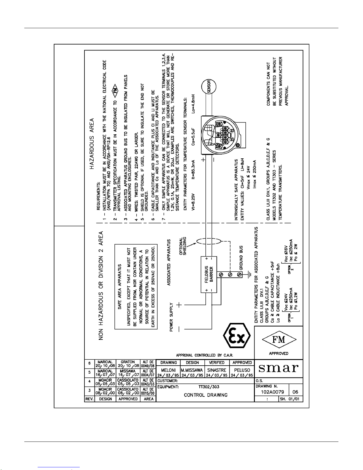
"
Factory Mutual (FM)
Egtvkhkecvkqpu"Kphqtocvkqp"
C0;"

VV525"⁄"Qrgtcvkqp"cpf"Ockpvgpcpeg"Kpuvtwevkqp"Ocpwcn"
"
C032"
Appendix B
SRF–SERVICE REQUEST FORM
Proposal No.:
Company:
Unit:
Receipt of
Remittance:
Warranty
Yes ( )
Purchase Order:
No ( )
COMMERCIAL CONTACT
TECHNICAL CONTACT
Full name:
Full name:
Position:
Position:
Phone: Extension:
Phone: Extension:
Fax:
Fax:
Email:
Email:
EQUIPMENT DATA / TEMPERATURE SENSOR
Model:
TT301 ( )
TT302 ( )
TT303 ( )
TT400SIS ( )
TT411 ( )
TT421 ( )
Serial Number:
Sensor Type and Connection:
Measurement type:
( ) Double Sensor ( ) Average between Sensors
( ) Differential ( ) Backup ( ) Single
INFORMATION AND DESCRIPTION OF THE FAILURE
Environment Temperature (ºC)
Work Temperature (ºC)
Calibration Range
Min:
Max:
Min :
Max:
Min:
Max:
Operation Time:
Failure Data:
IMPORTANT COMMENTS ABOUT EQUIPMENT APPLICATION AND PROCESS
(Please, inform more details about the application, installation, etc.).
FAILURE DESCRIPTION OR BAD OPERATION
(Please, describe the behavior of the fail, if it is repetitive, how it exactly happens, and so on.)
NOTES
For warranty or non-warranty repair, please contact your representative.
Further information about address and contacts can be found on www.smar.com/contactus.asp.
B.1

Service Request Form
B.2
 Loading...