


,
MAR / 03
Foundation Fieldbus www.esma-rt.ru
V ersion
1.1 / 1.2 / 2.0
P C I 3 0 2 O M M E

Specifications and information are subject to change without notice.
Up-to-date address information is available on our website.
smar
www.esma-rt.ru
web: www.esma-rt.ru

Table of Contents
Table of Contents
INTRODUCTION............................................................................................................................................. 1
General Features ..........................................................................................................................................................2
Powerful Hardware Architecture..................................................................................................................................................2
Open Software Architecture.........................................................................................................................................................2
Easy Installation & Expansibility ..................................................................................................................................................2
Fieldbus Link Master.................................................................................................................................................................... 2
Process Supervision.................................................................................................................................................................... 2
Flexible Bridge............................................................................................................................................................................. 2
Upgradeable Firmware ................................................................................................................................................................2
Isolated Passive Fieldbus MAU...................................................................................................................................................2
Description....................................................................................................................................................................2
Hardware Overview ......................................................................................................................................................3
CPU (Central Processing Unit)....................................................................................................................................................4
DP (Dual Port RAM) .................................................................................................................................................................... 4
Control Logic................................................................................................................................................................................ 4
PC Bus (Computer Expansion Bus)............................................................................................................................................. 4
Local Bus (High Speed Wide Bus)............................................................................................................................................... 4
Peripheral Bus.............................................................................................................................................................................4
Timer
Modem
MAU
NVRAM (Non-Volatile Random Access Memory)........................................................................................................................ 4
Software Overview........................................................................................................................................................5
HMI (Human-Machine Interface).................................................................................................................................................. 5
PCI OLE Server........................................................................................................................................................................... 5
PCI302 Device Driver .................................................................................................................................................................. 5
DP (Dual Port RAM) .................................................................................................................................................................... 5
CH
PCI302
Interfacing with HMI (Human-Machine Interface)......................................................................................................5
PCI302 Technical Specifications.................................................................................................................................6
PC Bus.........................................................................................................................................................................................6
CPU............................................................................................................................................................................................. 6
Memory........................................................................................................................................................................................ 6
Fieldbus Interface........................................................................................................................................................................6
General........................................................................................................................................................................................ 6
Physical Dimensions.................................................................................................................................................................... 6
APPENDIX A................................................................................................................................................... 7
DIP Switches and LEDs................................................................................................................................................7
PCI302 Version 1.xx....................................................................................................................................................................7
PCI302 Version 2.0...................................................................................................................................................................... 7
APPENDIX B................................................................................................................................................... 8
Physical Dimensions....................................................................................................................................................8
PCI302 Version 1.1x.................................................................................................................................................................... 8
PCI302 Version 1.2x.................................................................................................................................................................... 8
PCI302 Version 2.0...................................................................................................................................................................... 9
APPENDIX C................................................................................................................................................. 10
SC71 Cable Specification...........................................................................................................................................10
PIN Description..........................................................................................................................................................................10
.......................................................................................................................................................................................4
0 - 5
(Fieldbus Communications Controller) ....................................................................................................................... 4
0 - 3
(Fieldbus Medium Attachment Unit) ...............................................................................................................................4
0 - 3
(PCI302 Fieldbus ports 0 - 63)......................................................................................................................................... 5
0 - 63
(Process Control Interface 1 to 8)................................................................................................................................5
1/8
III

PCI302 - Operation & Maintenance Instructions Manual
APPENDIX D................................................................................................................................................. 11
Installation...................................................................................................................................................................11
Hardware Configuration.............................................................................................................................................11
PCI302 V2.0 .............................................................................................................................................................................. 11
PCI302 V1.xx.............................................................................................................................................................................11
Hardware Installation .................................................................................................................................................12
PCI302 V2.0 .............................................................................................................................................................................. 12
PCI302 V1.xx.............................................................................................................................................................................12
Software Installation....................................................................................................................................................................12
Updating the Firmware ................................................................................................................................................................ 13
APPENDIX E – SRF – SERVICE REQUEST FORM...................................................................................E.1
APPENDIX F - SMAR WARRANTY CERTIFICATE.................................................................................... F.1
IV

Introduction
PCI302 - Operation & Maintenance Instructions Manual
PCI302 - PROCESS CONTROL INTERFACE
The PCI302 (Process Control Interface) is a high performance Fieldbus interface that combines
advanced process control with multiport communications management.
PCI302 is a card designed to work inside industrial or commercial PCs. Featuring independent
Fieldbus H1 (31.25Kbps) master ports and powered by a 32-bit RISC CPU. Directly conn ected to
the PC bus (through PCI bus or ISA bus), it provides a fast communication path between the
Fieldbus and PC applications.
H
I
G
H
P
E
R
F
O
3
2
R
b
M
i
t
A
R
N
I
C
S
E
C
C
P
U
S
M
A
R
D
F
E
I
E
D
L
I
C
D
A
B
T
U
E
S
D
M
O
D
E
M
S
F
5
I
0
E
0
L
V
D
A
B
C
U
S
E
S
I
S
O
L
A
T
I
O
N
I
N
D
U
S
T
R
I
A
C
L
O
R
M
A
P
C
A
K
T
I
B
L
E
F
U
L
L
A
3
R
2
b
C
i
H
t
I
T
E
C
T
U
R
H
E
I
G
H
S
D
P
U
E
A
E
L
D
P
O
R
T
R
A
M
1
6
B
i
t
I
S
A
B
U
S
Figure 1 - Perspective View of a PCI302 card Version 1.1x.
Part Number
PCI302 Process Control Interface
1

PCI302 - Operation & Maintenance Instructions Manual
General Features
Powerful Hardware Architecture
The 32-bit super-scalar RISC CPU and dual port memory based architecture ensure high
processing power to PCI302. All communication and process control tas ks are internally executed,
keeping the PC free to implement the best HMI and the Smar PCI OLE Server.
Open Software Architecture
The PCI OLE Server
interfaces. Clients can access the server located on the same PC or on a remote through
LAN/WAN. This enables the same distributed Fieldbus database to be widely shared among
workstations.
Easy Installation & Expansibility
The PCI302 PCI (Peripheral Component Interconnect) bus version can be eas ily installed. (PCI bu s
specification v2.1) (*). Unique hardware design allows the installation of up to ei ght PCI302 cards
(depending on the number of free PCI bus slots) on one PC bus. No board configuration is
necessary for the installation. The PC’s plug and play system allocates the addressing resources for
the board operation.
The PCI302 ISA bus version can also be easily installed on the ISA or EISA bus of any ATcompatible PC. Unique hardware design allows the installation of up to eight PCI302 cards
(depending on the number of free ISA slots) on one PC bus, sharing the same I/O port and interrupt.
Fieldbus Link Master
The PCI302 can manage each of its Fieldbus ports
Process Supervision
Exploring advanced communication features of the Fieldbus protocol, the PCI302 can be used as an
efficient supervision interface. The function block parameters of field devices can be monitored
(cyclic or acyclic reads) or actuated (acyclic writes) through the PCI302 supervision s ervices. HMI
like supervisory systems and configur ators, running on the host PC, can interface to the PCI302s,
keeping complete hardware and Fieldbus protocol transparency.
Flexible Bridge
The PCI302 open software architecture enables data sharing between independent Fieldbus ports.
Upgradeable Firmware
PCI302's firmware (on-board executable program) remains in FLASH memory. As these memorie s
are in-circuit programmable, the user can change th e PCI302 firmware (upgrade software release,
change protocol, etc.) without removing components - just run the FBT ools utility and everything is
done by software.
Isolated Passive Fieldbus MAU
Its galvanically isolated Medium Attachment Unit
This enables the user to plug any PCI302 port on a fully loaded Fieldbus.
interconnects one or more simultaneous client applications with Fieldbus
as a link master device.
s
is passive (not powered by the Fieldbus network).
Description
At both, hardware and software levels, the PCI302 card was designed to handle all necessary
communication and process control tasks, minimizing the PC overload.
Typical Applications
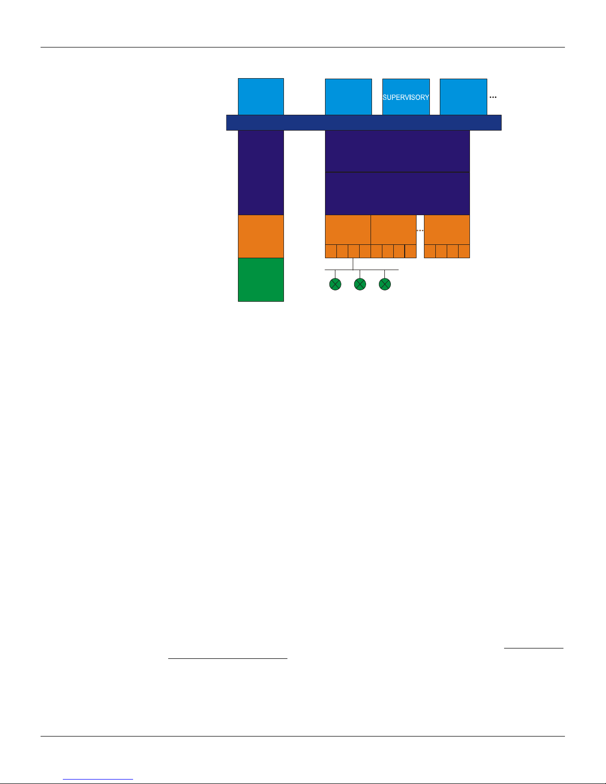
The PCI302 can be used in a wide range of Fieldbus-based ap plications. The next figure shows a
generic Field Control System from which many real applications can be derived.
* See note page 16.
2

Hardware Overview
PCI302 - Operation & Maintenance Instructions Manual
Figure 2 - Fieldbus Typical Application using PCI302 cards.
Remarks
• 1 to 8 PCI302 cards can be installed in the same PC Server.
• Up to 4 ports in each PCI302 Fieldbus line connected.
• Redundant operation (1 to 4 PCI302s on each Fieldbus, distributed on different PCs).
• F ield bus configuration, management and supervision.
• Network access via Ethernet (Client/Server architecture via DCOM).
TIMER
TIMER
MODEM
MODEM
MODEM
MODEM
0.2
3.5
0
1
2
3
MAU
MAU
MAU
MAU
0
1
2
3
F
I
E
L
D
B
U
S
CPU
FLASH
NVRAM
P
C
B
U
S
DP
L
O
C
A
L
B
U
S
CONTROL
LOGIC
P
E
R
I
P
H
E
R
A
L
B
U
S
Figure 3 – PCI302 Hardware Diagram.
3

PCI302 - Operation & Maintenance Instructions Manual
CPU (Central Processing Unit)
A 32-bit super-scalar RISC processor that handles all communication and control tasks performe d
by the PCI302.
DP (Dual Port RAM)
16-bit data memory shared with the PC through the PC bus. Both PCI302 and PC CPUs have
simultaneous access to this memory, providing an efficient communication path between them.
Control Logic
Internal control logic to handle the CPU access to all devices (RAM, NVRAM, FLASH, TIMERs,
MODEMs), and the DP arbitration mechanism.
PC Bus (Computer Expansion Bus)
A PCI bus (specification v2.1) (*), 16-bit ISA or 32-bit EISA bus, on which the PCI302 c ards are
plugged. It provides power and PC access to the card.
Local Bus (High Speed Wide Bus)
A 32-bit internal bus that interconnects the CPU to fast devices (RAM, NVRAM, FLASH and DP).
Peripheral Bus
8-bit peripheral bus used by the CPU to connect to slow devices (TIMERs and MODEMs).
Timer
8/16-bit 3-channel universal timers, used by the PSM-Real Time Kernel as a time base for task
switching and the Fieldbus communication timing.
Modem
The Smar Fieldbus chips that serialize the data communication at a 31.25Kbps baud rate. It is ISASP50 Fieldbus Physical Layer Specification compliant.
MAU
A signal conditioning and isolation circuit that adapts the digi tal signal (0/ 5V) from the modem to th e
Fieldbus lines, according to the ISA-SP50.02-1992 Fieldbus Physical Layer Specification. The
PCI302 MAU is passive, that is, not powered by the bus.
NVRAM (Non-Volatile Random Access Memory)
The 32-bit data memory is where the PCI302 data structures and objects are stored.
FLASH (Flash Memory)
32-bit code memory, where the PCI302 program is stored.
0 - 5
(Fieldbus Communications Controller)
0 - 3
(Fieldbus Medium Attachment Unit)
0 - 3
4
Software Overview
PCI302 - Operation & Maintenance Instructions Manual
Application
Clients
PC
Server
PCIs
FIELDBUS
SYSCON
OLE DCOM
PCI
0
11
22
Figure 4 – PCI302 Hierarchy Layers.
HMI (Human-Machine Interface)
User application program (configurator, supervisory, analyz e r, etc.) runn ing on P C(s) and i nterfacing
with the PCI302 card through a specific server for the services.
PCI OLE Server
Server for PCI302s based on Client/Server architecture, providing a consi stent set of functions for
Supervision and Configuration. It standardizes and simplifies the HMI access to the hardware.
PCI302 Device Driver
Specific hardware driver for Windows NT and 20 00 Operating System, impleme nting effectively the
access to local PCI302s.
DP (Dual Port RAM)
Memory shared by the PCI302 and PC, at hardware and software levels, which contains all
structures required for data and command transfer between them.
(PCI302 Fieldbus ports 0 - 63)
CH
0 - 63
The card independent ports, running inside the PCI302. Each one includes the Physical layer and
part of the Data Link layer.
PCI302
(Process Control Interface 1 to 8)
1/8
A maximum of 8 PCI302 cards may coexist in a PC bus, totaling 32 ports.
Interfacing with HMI (Human-Machine Interface)
A generic HMI (Human-Machine Interface), like supervisory systems, configurators, etc., interfaces
with Smar Fieldbus devices through the PCI302 c ard, using the PCI OLE Server specification. T he
generic HMI may work under Windows 95, NT and 2000.
The PCI OLE Server is a 32-bit version server for Windows NT (in compliance with OPC - OLE for
Process Control specification). This enables OPC clients to supervis e the Fieldbus system through
Smar interfaces, in a standardized way (without specific drivers).
For other platforms (OS/2, QNX, etc.), system integrators may also write drivers that access the
PCI302 directly, since Smar provides no drivers for them.
PCI OLE Server
PCI NT Device Driver
PCI
0
3
1
0
3
PCI
0
1
FBTOOLS
7
3
2
5
PCI302 - Operation & Maintenance Instructions Manual
PCI302 Technical Specifications
PC Bus
Type ISA (16-bit slot) or EISA PCI (specification v2.1) (*)
Hardware Interrupt IRQ 5, 10, 11, 12 or 15 none
I/O Port Base 240H, 280H, 300H or 340H Plug and Play allocation
I/O Port Area 48 contiguous bytes
I/O Access 16-bit 16-bit
Dual Port RAM (I/O accessed) 256KB, 16-bit 256KB, 16-bit
CPU
Memory
PCI302 Version 1.1x PCI302 Versions 1.2x and 2.0
Code Area
Data Area
Fieldbus Interface
General
!!!!!!!!!!!!!!!!!!!!! PCI302 VERSIONS 1.XX PCI302 Version 2.0
Operating Conditions 0ºC to +50 ºC @ 5% to 90% RH 0 ºC to +50 ºC @ 5% to 90% RH
Non-operating Conditions -30 ºC to +70 ºC @ 5% to 90% RH -30ºC to +70ºC @ 5% to 90% RH
Operating Voltage +5V ±5% +5V ±5% and +3.3V ± 10%
Operating Current 1.2A (typ)
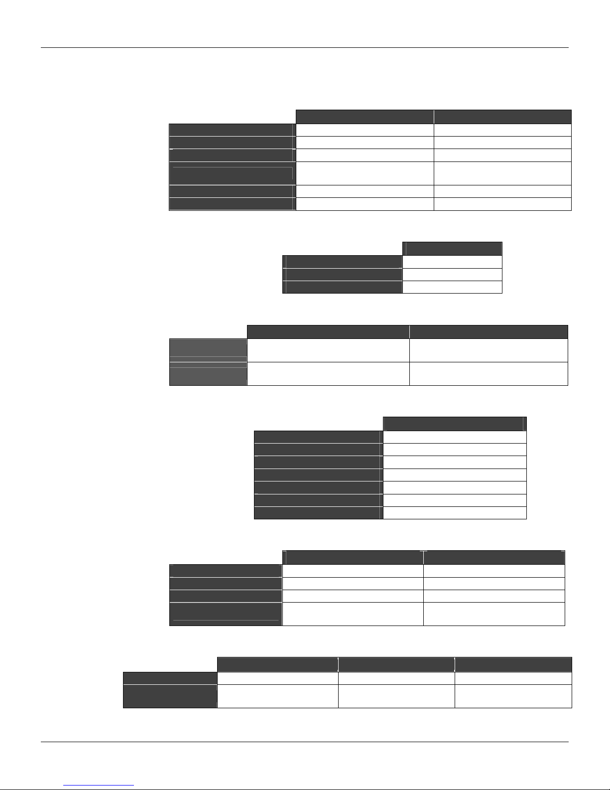
Physical Dimensions
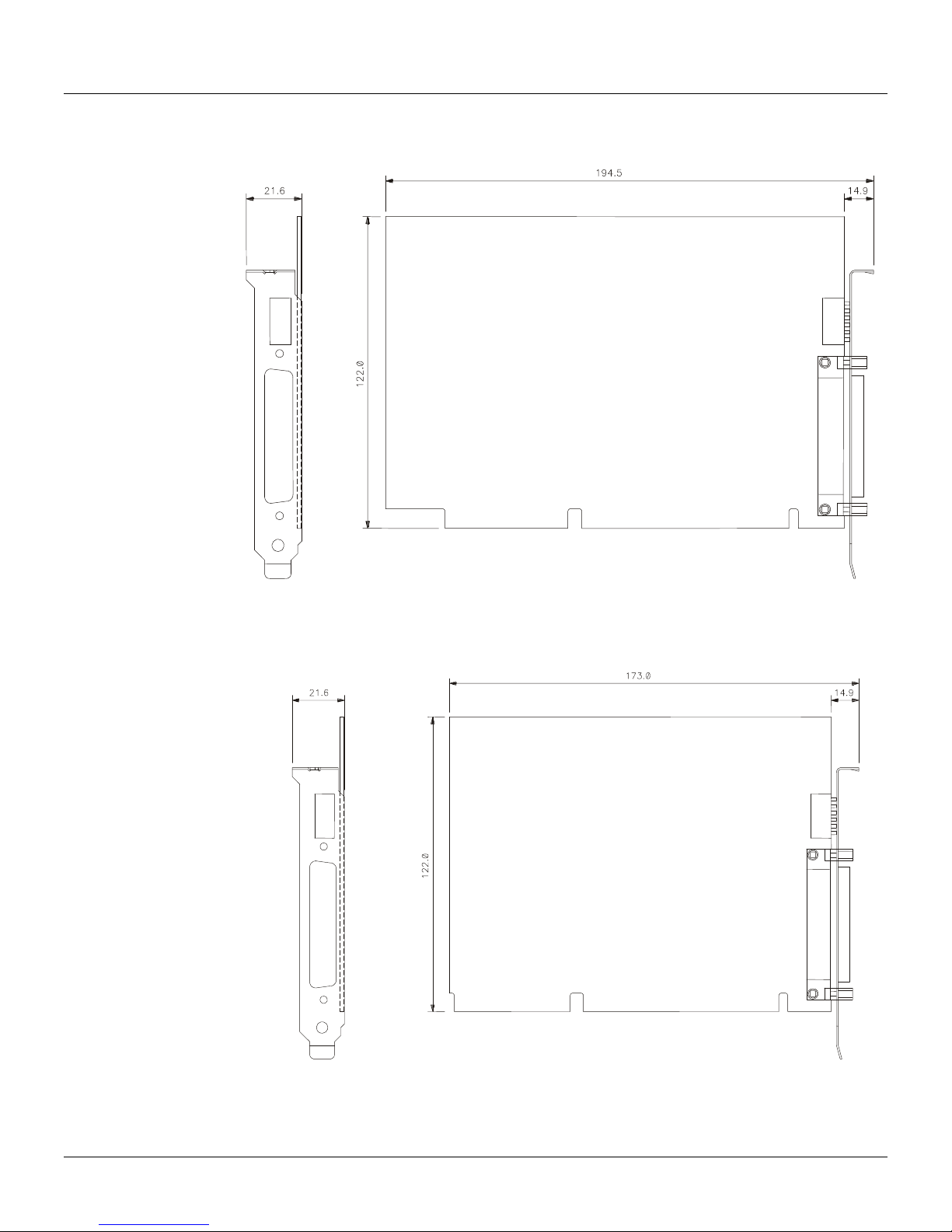
PCI302 Version 1.1x PCI302 Version 1.2x PCI302 Versions 2.0
Standard ISA 16-bit ISA 16-bit PCI bus
External Dimensions
173.0 x 21.6 x 141.6mm (max)
(Data and configuration retention)
PCI302
Number of ports 4, independents with DMA
Physical Layer Standard ISA-S50.02-1992
Baud Rate 31.25Kbps (H1)
MAU Type Passive (not bus powered)
Intrinsic Safety NOT compliant
Isolation 500 VAC (each port)
Connector 37-pin D-SUB, male
6.85 x 0.85 x 5.57"
PCI302 Version 1.xx PCI302 Version 2.0
Type 32-bit RISC
Sustainable Performance 50 MIPS
Peak Performance 75 MIPS
1MB, 32-bit Flash Memory
(Upgradeable firmware)
512KB, 32-bit NVRAM
(Data and configuration retention)
1.19A (typ) / +5V Power Supply
0.085A (typ) / +3.3V Power Supply
194.5 x 21.6 x 141.6 mm (max)
7.65 x 0.85 x 5.57"
48 contiguous bytes (interface)
80 contiguous bytes (configuration)
PCI302
1MB, 32-bit Flash Memory
(Upgradeable firmware)
2MB, 32-bit NVRAM
234.9 x 21.6 x 125.0 mm (max)
9.25 x 0.85 x 5"
6

Appendix A
DIP Switches and LEDs
PCI302 Version 1.xx
W1 W2 W3 Card W4 W5 I/O PORT
0 0 0
0 0 1 1 0 1
0 1 0 2 1 0 300 - 32FH
0 1 1 3 1 1 340 - 36FH
1 0 0 4
1 0 1 5
1 1 0 6 0 ON (data retention)
1 1 1 7
The interrupt (IRQ5, IRQ10, IRQ11, IRQ12 or IRQ15) is software configured with the FBtools or
ItfSetup programs.
The switch W6 (NVRAM BATTERY) is factory set to the OFF position in order to avoid energy loss
while the card is at Smar`s stock or on the Customer’s shelf. BEFORE USING THE PCI302 V1.xx,
THE DIP6 SHOULD BE TURNED ON.
PCI302 Version 2.0
LED Color Name Description
1 Red FAIL When ON, it indicates reset condition or CPU failure.
2 Green Dual Port
3 Green FF H1-1 Indicates transmission through the first H1 port.
4 Green FF H1-2 Indicates transmission through the second H1 port.
5 Green FF H1-3 Indicates transmission through the third H1 port.
6 Green FF H1-4 Indicates transmission through the fourth H1 port.
0*
0 = ON = LOWER POSITION
1 = OFF = UPPER POSITION
* = Factory default setting
Table 1 – PCI302 1.xx Dip Switches.
NOTES
WARNING!
When blinking, it indicates communication through the
Dual Port.
Table 2 – PCI302 2.00 LEDs.
0 0 240 - 26FH
W6 NVRAM BATTERY
1 OFF (data loss)*
280 - 2AFH*
7
Appendix B
Physical Dimensions
PCI302 Version 1.1x
PCI302 Version 1.2x
Figure 5 - PCI302 card V1.1x Physical dimensions (mm).
8
Figure 6 - PCI302 card V1.2x Physical dimensions (mm).
PCI302 - Operation & Maintenance Instructions Manual
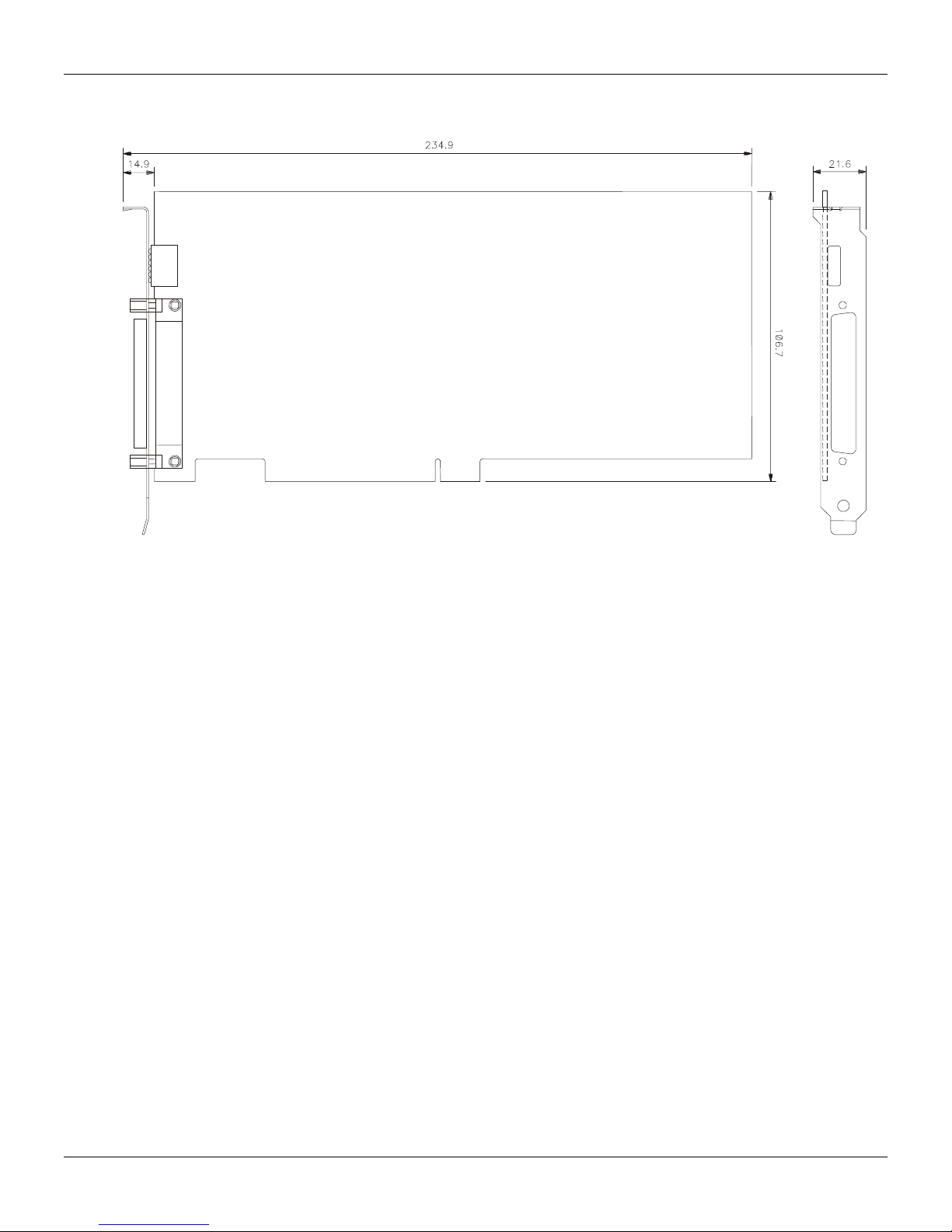
PCI302 Version 2.0
Figure 7 - PCI302 card V2.0 Physical dimensions (mm)
9

Appendix C
SC71 Cable Specification
PIN Description
1 Signal 2
18 0DATA+ 0D+
36 0DATA- 0D16 1DATA+ 1D+
34 1DATA- 1D14 2DATA+ 2D+
32 2DATA- 2D12 3DATA+ 3D+
30 3DATA- 3D-
NC GND (shield) GND
Table 1 - SC71 Pin Description
Figure 8 - SC71 Pin view.
10

Appendix D
Installation
Any user can do the PCI302 hardware and software installation quite easily, with a reasonable
knowledge in Fieldbus and PCs.
Hardware Configuration
PCI302 V2.0
No hardware configuration is necessary for PCI302 V2.0.
PCI302 V1.xx
The first step is to verify the PC settings and identify the I/O address and the available interruptions
for the PCI302 v1.xx card.
All of the PCI302 cards installed in the PC bus must be set with the same I/O port and same IRQ,
but each one of them with a different card number. The I/O and IRQ of the PCI302 must not
conflict with all the other cards (besides PCI302s) already installed in the PC.
Select a card number (usually starting from 0) to each PCI302 card to be installed in the PC. Take
note of each card and its respective serial number.
The PCI302 hardware is set through the dip switches located in the back of the card (see figure 9).
IMPORTANT
FY1PM105.CDR
Figure 9- Dip Switches of PCI302 v1.xx card
PCI302 DIP SWITCHES
W1 W2 W3 CARD W4 W5 I/O W6 NVRAM BATTERY
0 0 0 0* 0 0 240- 26FH 0 ON
0 0 1 1 0 1 280- 2AFH* DATA RETENTION
0 1 0 2 1 0 300- 32FH 1 OFF*
0 1 1 3 1 1 340- 36FH DATA LOSS
1 0 0 4
1 0 1 5
1 1 0 6
1 1 1 7 *FACTORY SETTINGS
ATTENTION
The Dip switches have external access even after the card hav e been installed in the PC. The
user can change its positions while the PC is on, but NEV ER when an application in the PC that
accesses the PCI302 is running.
NOTES
1- In some PCs, IRQ15 is reserved for the secondary HDD control. In case it is necessary to
free the IRQ15 to use in the PCI302s, disable this controller (when not in use), running the PC
setup.
2- The IRQ 12 is usually saved for the mouse PS/2.
3- The PCI302 v1.2 interruption (IRQ5, IRQ10, IRQ11, IRQ12 or IRQ15) is set via tool software
FBtools or ItfSetup.
11

The W6 Dip_Switch (NVRAM battery) is set in factory to OFF, in order to avoid energy loss while
the card is kept in stock in the Smar’s installations or Customer’s installations. The W6
DIP_Switch must be turned ON before using the PCI302 V1.2
Hardware Installation
PCI302 V2.0
First, install the SYSTEM302 with the PCI302 V2.0 option, then, connect the PCI302 V2.0 to the
computer. Thus, all of the Windows installation procedures will be performed automatically.
If the SYSTEM302 is not installed and a PCI302 V2.0 is connected to the PC, the Windows progr am
will request a device driver for the PCI302 V2.0. In this case, insert the SYSTEM302 installati on CD
and instruct the Windows’ Hardware installation program to install the device driver through the
CD_ROM.
PCI302 V2.0 can be easily installed in the PCI bus (specification v 2.1) (*) of every commercial or
industrial PC. Refer to the computer manual for instructions on ho w to inst all and rem ove PCI car ds.
Turn off the PC before inserting or removing the PCI302s from the bus. There is a limit of up to 8
PCI302 cards in the PC bus.
For appropriate refrigeration to the PCI302 cards keep the PC cabinet closed while it is ON.
The PCI302 V2.0 is not compatible with PCI302 V1.xx. T he two types of cards can be physical ly
installed on the same computer but just one will work with the SYSTEM 302.
PCI302 V1.xx
After the hardware configuration, turn on your PC again and check the functionality of all the
hardwares installed in your PC to detect possible conflicts after the installation of the PCI302. If
there is any abnormal operation, start again with the installation procedures.
After the hardware configuration have been done, the PCI 302 v1.xx can be installed in the ISA bus
(16 bits slots) or EISA of every commercial or industrial PC. Refer to the computer manual for
instructions on how to install and remove ISA cards. Turn off the PC before inserting or removin g
the PCI302s from the bus. There is a limit of up to 8 PCI302 cards in the PC bus.
For appropriate refrigeration to the PCI302 cards. Keep the PC cabinet closed while it is ON.
The PCI302 V1.0 is not compatible with PCI302 V1.2. In case it is necessary to install the PCI302
V1.0 and V1.2 in the same PC, please contact Smar Technical Support and make a request to
exchange the PCI302 V1.0 for PCI302 V1.2.
PCI302 V1.1 is fully compatible with PCI302 V1.2.
PCI302 - Operation & Maintenance Instructions Manual
IMPORTANT
NOTES
NOTES
Software Installation
During the SYSTEM302 installation process, a dialog box will appear re questing the type of PCI3 02
to be used (versions between 1.x and 2.0) or not to use a PCI302.
The option chosen by the user can be changed later by using the Interface Setup (ItfSetup) program
of the SYSTEM302.
Please refer to the System 302 documentation for more details.
12
PCI302 - Operation & Maintenance Instructions Manual
Updating the firmware
While downloading a PCI302 firmware, all fieldbus activities in the PCI302 will stop. After the
firmware download is done, it will be necessary to download the PCI302 configuration via Syscon.
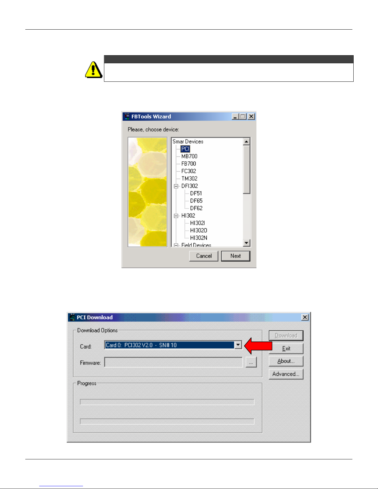
1. Launch the FBTools Wizard, located in the Start menu
Wizard.
ATTENTION
Æ
ProgramsÆ System302Æ FBTools
2. Select PCI and click Next.
3. Select the desi red PCI card.
13

PCI302 - Operation & Maintenance Instructions Manual
4. Click the Browse... button to select the firmware file to be downloaded (PCI*.abs file).
5. After selecting the firm ware file, the Download button will be enabled. Click on it to initiate th e
firmware download.
6. A message box will come up requesting a confirmation. Click Ok to continue.
14

PCI302 - Operation & Maintenance Instructions Manual
7. The progress bar at the bottom of the dialog box will show the progress of the operation.
8. When the download is complete, a dialog box will appear confirming that the program was
downloaded successfully. Click OK and wait a few minutes while the information is updated.
9. Click Close to exit the PCI Download dialog box.
15

PCI302 - Operation & Maintenance Instructions Manual
NOTE (*)
PCI302 v2.0 card follows PCI bus specification version 2.1. However it is recommended to be
used on PCI bus specification version 2.2 systems.
To operate on a PCI v2.1 specification system, the 5 volts keyed PCI connectors must provide 3.3
volts power. This characteristic is optional in PCI 2.1 specification but many of such systems
provide 3.3 volts on all connectors. In PCI 2.2 specification this 3.3 volts supply is a requirement.
Therefore PCI302v2.0 operates normally on PCI 2.2 specification systems.
To identify the PCI bus specification version, it is necessary to check the PC´s manufacturer
documentation. The PCI specification version 2.2 was released in December of 1998. Since then,
many PC systems have been built PCI bus specification 2.2 compliant.
16

Appendix E
smar
SRF – Service Request Form
Proposal Nº:
PCI302 – Process Control Interface
Company: _____________________________________________________________________________________________________
Unit: ________________________________________________________________________________________________________
Invoice: _______________________________________________________________________________________________________
COMMERCIAL CONTACT
Full Name:
Phone: _________ _________________________ _________ _________________________ Fax: _______________________
E-mail: _______________________________________________________________________________________________________
TECHNICAL CONTACT
Full Name: ________________________________________________________________________________________________
Phone: _________ _________________________ _________ _________________________ Extension: ____________________
E-mail: _______________________________________________________________________________________________________
____________________________________________________________________________________________________
COMPANY INFORMATION
EQUIPMENT DATA
Model: ______________________________________________________________________________________________________
Serial Number: ________________________________________________________________________________________________
PROCESS DATA
Process Type (Ex. boiler control): __________________________________________________________________________
Operation Time: ____________________________________________________________________________________________
Failure Date: __________________________________________________________________________________________________
FAILURE DESCRIPTON
(Please, describe the failure. Can the error be reproduced? Is it repetitive?)
______________________________________________________________________________________________________________
______________________________________________________________________________________________________________
______________________________________________________________________________________________________________
______________________________________________________________________________________________________________
OBSERVATIONS
______________________________________________________________________________________________________________
______________________________________________________________________________________________________________
______________________________________________________________________________________________________________
______________________________________________________________________________________________________________
USER INFORMATION
Company: _____________________________________________________________________________________________________
Contact: _______________________________________________________________________________________________________
Section: _______________________________________________________________________________________________________
Title: _________________________________________________ Signature:_______________________________________________
Phone: _________ _________________________ _________ _________________________ Extension: ___________________
E-mail: ________________________________________________________________________ Date: ______/ ______/ _________
For warranty or non-warranty repair, please contact your representative.
Further information about address and contacts can be found on www.smar.com/contactus.asp
E.1

PCI302 - Operation & Maintenance Instructions Manual
E.2

Appendix F
SMAR WARRANTY CE R TIF ICATE
1. SMAR guarantees its products for a period of 24 (twenty four) months, starting on the day of
issuance of the invoice. The guarantee is valid regardless of the day that the product was
installed.
2. SMAR products are guaranteed against any defect originating from manufacturing, mounting,
whether of a material or manpower nature, provided that the technical analysis reveals the
existence of a quality failure liable to be classified under the meaning of the word, duly verified
by the technical team within the warranty terms.
3. Exceptions are proven cases of inappropriate use, wrong handling or lack of basic maintenance
compliant to the equipment manual provisions. SMAR does not guarantee any defect or
damage caused by an uncontrolled situation, including but not limited to negligence, user
imprudence or negligence, natural forces, wars or civil unrest, accidents, inadequate
transportation or packaging due to the user’s responsibility, defects caused by fire, theft or stray
shipment, improper electric voltage or power source connection, electric surges, violations,
modifications not described on the instructions manual, and/or if the serial number was altered
or removed, substitution of parts, adjustments or repairs carried out by non-authorized
personnel; inappropriate product use and/or application that cause corrosion, risks or
deformation on the product, damages on parts or components, inadequate cleaning with
incompatible chemical products, solvent and abrasive products incompatible with construction
materials, chemical or electrolytic influences, parts and components susceptible to decay from
regular use, use of equipment beyond operational limits (temperature, humidity, etc.) according
to the instructions manual. In addition, this Warranty Certificate excludes expenses with
transportation, freight, insurance, all of which are the customer’s responsibility.
4. For warranty or non-warranty repair, please contact your representative.
Further information about address and contacts can be found on www.smar.com/contactus.asp
5. In cases needing technical assistance at the customer’s facilities during the warranty period,
the hours effectively worked will not be billed, although SMAR shall be reimbursed from the
service technician’s transportation, meals and lodging expenses, as well dismounting/mounting
costs, if any.
6. The repair and/or substitution of defective parts do not extend, under any circumstance, the
original warranty term, unless this extension is granted and com municated in writing by SMAR.
7. No Collaborator, Representative or any third party has the right, on SMAR’s behalf, to grant
warranty or assume some responsibility for SMAR products. If any warranty would be granted
or assumed without SMAR’s written consent, it will be declared void beforehand.
8. Cases of Extended Warranty acquisition must be negotiated with and documented by SMAR.
9. If necessary to return the equipment or product for repair or analysis, contact us.
See item 4.
10. In cases of repair or analysis, the customer must fill out the Revision Requisition Form (FSR)
included in the instructions manual, which contains details on the failure observed on the field,
the circumstances it occurred, in addition to information on the installation site and process
conditions. Equipments and products excluded from the warranty clauses must be approved by
the client prior to the service execution.
11. In cases of repairs, the client shall be responsible for the proper product packaging and SMAR
will not cover any damage occurred in shipment.
F.1

PCI302 - Operation & Mainte nance Instr ucti o ns Manu al
12. In cases of repairs under warranty, recall or outside warranty, the client is responsible for the
correct packaging and packing and SMAR shall not cover any damage caused during
transportation. Service expenses or any costs related to installing and uninstalling the product
are the client´s sole responsibility and SMAR does not assume any accountability before the
buyer.
13. It is the custom er’s responsibility to clean and decontaminate products and accessories prior to
shipping them for repair, and S MAR and its dealer reserve themselves the right to refuse the
service in cases not compliant to those conditions. It is the customer’s responsibility to tell
SMAR and its dealer when the product was utilized in applications that contaminate the
equipment with harmful products during its handling and repair. Any other damages,
consequences, indemnity claims, expenses and other costs caused by the lack of
decontamination will be attributed to the client. Kindly, fill out the Declaration of
Decontamination prior to shipping products to SMAR or its dealers, which can be accessed at
www.smar.com/doc/declarationofcontamination.pdf
14. This warranty certificate is valid only when accompanying the purchase invoice.
and include in the packaging.
F.2
 Loading...