


LD400
Smart Pressure Transmitter
OPERATION AND MAINTENANCE
INSTRUCTION / MANUAL
L D 4 0 0 M E

smar
www.smar.com
Specifications and information are subject to change without notice.
Up-to-date address information is available on our website.
web: www.smar.com/contactus.asp

Introduction
INTRODUCTION
LD400 HART® is a Smart Pressure Transmitter for differential, absolute, gauge, level and flow
measurements.
Diferential Transmitter – LD400D and LD400H
This model measures the differential pressure applied in the sensor. Normally, both sides of the
sensor are connected to the process and if the selected output function is linear, the measurement
is the differential pressure. If the selected output function is a square root, the measurement is a
fluid flow.
Flow Transmitter – LD400D and LD400H
The differential pressure is generated by an flow primary element and the square root function
supplies the measurement flow.
Gauge Pressure Transmitter – LD400M
This model has the Lower Side Input connected to a blind flange and open to atmosphere.
Therefore, this model measures the pressure relative to atmosphere and the output function can be
linear or linearized by the linearization table.
Absolut Pressure Transmitter - LD400A
This model has the Low Side Input connected to a blind flange and it is open to atmosphere.
Therefore, this model measures the pressure relative to local pressure and the output function can
be linear or linearized by the linearization table.
Level Transmitter – LD400L
This model is available as a flange mounted unit with a flush diaphragm for direct installation on
vessels. Extended dia phragms are also available.
The LD400 series use HART
configuration softwares or others supplier. The local adjustment is enable for all the LD400 series.
With ma gne t ic to ol s i s possible to configure the zero and the span, to alter the measurement range,
to alter the unit of measured pressure, to select the square root function, to operate the total ed value
or in a control loop.
With the AssetView from Smar is possible to do the diagnoses management field’s intrumented to
aid in the reative, preventive, predictive and proactive.
®
technology. This instruments can be configured through Smar
I

LD400 - Operation and Maintenance Instruction Manual
The contents of this manual abides by the hardware and software used on the current equipment
version. Eventually there may occur divergencies between this manual and the equipment. The
lly reviewed and the necessary or identified corrections
e
product and, in addition, it does not cover every possible mounting, operation or maintenance
Before installing and utilizing the equipment, check if the model of the acquired equipment complies
If the user needs more information, or on the event of specific problems not specified or treated in
this manual, the information should be sought from Smar. Furthermore, the user recognizes that the
of this manual by no means modify past or present agreements, confirmation or judicial
ar’s obligation result from the purchasing agreement signed between the parties, which
warranty term. Contractual clauses related to the warranty are
on,
startup and maintenance of the equipment. Qualified personnel are understood to be the persons
familiar with the mounting, electrical connection, startup and operation of the equipment or other
k. Smar provides specific training to instruct and
qualify such professionals. However, each country must comply with the local safety procedures,
legal provisions and regulations for the mounting and operation of electrical installations, as well as
the laws and regulations on classified areas, such as intrinsic safety, explosion proof, increased
The user is responsible for the incorrect or inadequate handling of equipments run with pneumatic
ydraulic pressure or, still, subject to corrosive, aggressive or combustible products, since their
areas, has
its certification void when having its parts replaced or interchanged without functional and approval
tests by Smar or any of Smar authorized dealers, which are the competent companies for certifying
applicable standards and regulations. The same is true
when converting the equipment of a communication protocol to another. In this case, it is necessary
sending the equipment to Smar or any of its authorized dealer. Moreover, the certificates are
Always respect the instructions provided in the Manual. Smar is not responsible for any losses
to
Waiver of responsibility
information from this document are periodica
will be included in the following editions. Suggestions for their improvement are welcome.
Warning
For more objectivity and clarity, this manual does not contain all the detailed information on th
cases.
with the technical requirements for the application. This checking is the user’s responsibility.
contents
relationship, in whole or in part.
All of Sm
includes the complete and sole valid
not limited nor extended by virtue of the technical information contained in this manual.
Only qualified personnel are allowed to participate in the activities of mounting, electrical connecti
similar apparatus that are technically fit for their wor
with
safety and instrumented safety systems, among others.
or h
utilization may cause severe bodily harm and/or material damages.
The field equipment referred to in this manual, when acquired for classified or hazardous
that the equipment in its entirety meets the
different and the user is responsible for their correct use.
and/or damages resulting from the inadequate use of its equipments. It is the user’s responsibility
know and apply the safety practices in his country.
II

Introduction
Isolator
EEPROM with Sensor Data
Temperature Data
Resonant Oscillator
Digital
Reading
Zero/Span Local
Adjustment
- D/A Converter
- HART Modem
- LCD Controller
- Mathematical
Co-processor
- Range
- Special Functions
- PID
- Output Controller
- Communication
- HART
- Advanced Diagnostic
- Firmware Update
Process Unit
Protocol
S
i
g
na
l
C
o
nd
i
t
i
o
ne
r
I
n
p
u
t
/
O
u
t
p
u
t
PH
PL
Digital
Sensor
Glass
Metalized
Surface (4)
Filling Fluid (3)
Isolating
Diaphragm (2)
Sensor
Diaphragm (1)
HT3012
4 - 20mA
TRANSMITTER GENERAL VIEW
The LD400 HART® uses a highly proven technique for pressure measuring by capacitance reading.
The block diagram of the LD400 HART
®
pressure transmitter is shown below.
In the cell center is the sensor diaphragm (1). This diaphragm flexes in response to the different
pressures applied on the LOW and HIGH sides of the cell (PL and PH). These pressures are directly
applied on the isolator diaphragms (2), whose function is to isolate the sensor process and supply
high resistance against corrosion caused by process fluids. The pressure is transmitted directly to
the sensor diaphragm through the filling fluid (3) and causes its deflection. The sensor diaphragm is
a mobile electrode whose two metal surfaces (4) are stable electrodes. A deflection on the sensor
diaphragm is read by the capacitance variation between both stable and mobile electrodes.
The resonance oscillator reads the capacitance variations betw een the mobile and the sta ble board s
and generates a pressure output equivalent to the detected capacitance variation. This pressure
value is informed in compliance with the transmitter communication protocol. As the conversion
process does not involve an A/D converter, any errors or deviations are eliminated during the
process. Temperature compensation is done by a sensor, which combined with a precision sensor,
results in high accuracy and range.
The process variable, as well as the diagnostic monitoring and information, are supplied by the
digital communication protocol. The LD400 is available in the HART® communication protocol.
Read carefully these instructions for better use of the LD400 HART®. Smar pressure transmitters
are protected by American patents n. 6,433,791 and 6,621,443.
III

LD400 - Operation and Maintenance Instruction Manual
Acronym /
Abbreviation
Designation
Description
HFT
Hardware Fault Tolerance
The hardware fault tolerance of the device.
of the demanded function in case of faults or deviations.
MTBF
Mean Time Between Failures
This is the mean time period between two failures.
MTTR
Mean Time To Repair
This is the mean time period between the occurrence of a failure
in a device or system and its repair.
PFD
Probability of Failure on Demand
This is the likelihood of dangerous safety function failures
occurring on demand.
PFDAVG
Average Probability of Failure
This is the average likelihood of dangerous safety function
failures occurring on demand.
The International Standard IEC 61508 specifies four discrete
safety functions.
SFF
Safe Failure Fraction
The fraction of non-hazardous failures, e.g. the fraction of failures
related system to a
dangerous undetected state.
not greater than double the frequency of the periodic test.
DTM
Device Type Manager
The DTM is a software module which provides functions for
accessing device parameters, configuring and operating the
is not
executable software.
LRV
Device Configuration
Lower Range Value of the measurement range.
URV
Device Configuration
Upper Range Value of the measurement range.
In multidrop mode, up to 15 field devices are connected in
wire devices providing a fixed current of 4
mA.
Acronyms and Abbreviations
This is the capability of a functional unit to continue the execution
SIL Safety Integrity Level
safety integrity levels (SIL 1 to SIL 4). Each level corresponds to
a specific probability range regarding the failure of a safety
function. The higher the safety integrity level of the safety-related
systems, the lower likelihood of non-execution of the demanded
without the potential to set the safety-
Low Demand Mode Low Demand Mode of Operation Measuring mode with low demand rate, in which the demand rate
for the safety-related system is not more than once a year and is
Multidrop Multdrop Mode
devices and diagnosing problems. By itself, a DTM
parallel to a single wire pair. The analog current signal serves just
to energize the two-
IV

Table of Contents
TABLE OF CONTENTS
SECTION 1 - INSTALLATION .................................................................................................................. 1.1
GENERAL................................................................................................................................................................... 1.1
MOUNTING ................................................................................................................................................................ 1.1
ELECTRONIC HOUSING ......................................................................................................................................... 1.10
WIRING .................................................................................................................................................................... 1.10
TYPICAL INSTALLATION FOR HART® PROTOCOL .............................................................................................. 1.12
INSTALLATION IN HAZARDOUS LOCATIONS ...................................................................................................... 1.15
EXPLOSION/FLAME PROOF .................................................................................................................................. 1.15
INTRINSICALLY SAFE ............................................................................................................................................ 1.15
SECTION 2 - FUNCTIONAL DESCRIPTION ............................................................................................ 2.1
FUNCIONAL DESCRIPTION – HARDWARE ............................................................................................................ 2.2
FUNCTIONAL DESCRIPTION – LD400 HART® SOFTWARE .................................................................................. 2.4
FUNCTIONAL DESCRIPTION - DISPLAY (LCD) ...................................................................................................... 2.7
SECTION 3 - TECHNICAL CHARACTERISTICS ..................................................................................... 3.1
ORDERING CODE ..................................................................................................................................................... 3.7
SECTION 4 - CONFIGURATION .............................................................................................................. 4.1
GENERAL................................................................................................................................................................... 4.1
CONFIGURATION FEATURES ................................................................................................................................. 4.4
MANUFACTURING DATA AND IDENTIFICATION ................................................................................................... 4.4
PRIMARY VARIABLE TRIM – PRESSURE ............................................................................................................... 4.5
PRIMARY VARIABLE CURRENT TRIM .................................................................................................................... 4.6
TEMPERATURE TRIM ............................................................................................................................................... 4.6
TRANSMITTER ADJUSTMENT TO THE WORKING RANGE .................................................................................. 4.6
ENGINEERING UNIT SELECTION ........................................................................................................................... 4.7
TRANSFER FUNCTION FOR FLOW MEASUREMENT ........................................................................................... 4.9
TABLE POINTS ........................................................................................................................................................ 4.10
TOTALIZATION CONFIGURATION ........................................................................................................................ 4.10
PID CONTROLLER CONFIGURATION ................................................................................................................... 4.12
EQUIPMENT CONFIGURATION ............................................................................................................................. 4.13
EQUIPMENT MAINTENANCE ................................................................................................................................. 4.14
SECTION 5 - PROGRAMMING USING LOCAL ADJUSTMENT .............................................................. 5.1
THE MAGNETIC TOOL .............................................................................................................................................. 5.1
LOCAL ADJUSTMENT ............................................................................................................................................... 5.3
SIMPLE LOCAL ADJUSTMENT ................................................................................................................................ 5.3
COMPLETE LOCAL ADJUSTMENT .......................................................................................................................... 5.4
SIMULATION [SIMUL] ................................................................................................................................................ 5.6
RANGE [RANGE] ....................................................................................................................................................... 5.7
PRESSURE TRIM [TRIM] ........................................................................................................................................ 5.12
CONFIGURATION [CONF] ...................................................................................................................................... 5.14
OPERATION [OPER] ............................................................................................................................................... 5.21
EQUIPMENT CONFIGURED ON TRANSMITTER MODE ...................................................................................................... 5.21
EQUIPMENT CONFIGURED ON CONTROLLER MODE ....................................................................................................... 5.22
QUIT [QUIT] ............................................................................................................................................................. 5.24
SECTION 6 - MAINTENANCE .................................................................................................................. 6.1
DIAGNOSTIC USING CONFIGURATION TOOL....................................................................................................... 6.1
ERROR MESSAGES ................................................................................................................................................. 6.1
DIAGNOSTIC VIA TRANSMITTER ............................................................................................................................ 6.2
SENSOR ................................................................................................................................................................................... 6.4
ELECTRONIC CIRCUIT ............................................................................................................................................................ 6.6
REASSEMBLY PROCEDURE ................................................................................................................................... 6.6
SENSOR ................................................................................................................................................................................... 6.6
ELECTRONIC CIRCUIT ............................................................................................................................................................ 6.7
V

LD400 - Operation and Maintenance Instruction Manual
INTERCHANGEABILITY ............................................................................................................................................ 6.8
RETURNING MATERIALS ......................................................................................................................................... 6.8
LIFETIME TRANSMITTER ......................................................................................................................................... 6.8
ACESSORIES ............................................................................................................................................................ 6.9
SPARE PARTS LIST .................................................................................................................................................. 6.9
ORDERING CODE ................................................................................................................................................... 6.11
HART® SPECIAL UNITS .......................................................................................................................................... 6.16
SECTION 7 - SAFETY INSTRUMENTED SYSTEMS ............................................................................... 7.1
INTRODUCTION ........................................................................................................................................................ 7.1
SAFETY STANDARD ................................................................................................................................................. 7.1
APPLICATION STANDARDS..................................................................................................................................... 7.2
SAFETY FUNCTION .................................................................................................................................................. 7.2
FUNCTIONAL SAFETY PROPERTIES ..................................................................................................................... 7.3
ENVIRONMENTAL PROPERTIES ............................................................................................................................ 7.3
INSTALLATION .......................................................................................................................................................... 7.3
MODES OF OPERATION .......................................................................................................................................... 7.3
CONFIGURATION MODE ENABLING PROCEDURE .............................................................................................. 7.4
LD400 HART® SIS TECHNICAL CHARACTERISTICS ............................................................................................. 7.4
MAINTENANCE ......................................................................................................................................................... 7.6
APPENDIX A - CERTIFICATIONS INFORMATION ................................................................................. A.1
EUROPEAN DIRECTIVE INFORMATION ................................................................................................................. A.1
HAZARDOUS LOCATIONS CERTIFICATIONS ........................................................................................................ A.1
SOUTH AMERICA CERTIFICATION ....................................................................................................................................... A.1
EUROPEAN CERTIFICATIONS ............................................................................................................................................... A.2
IDENTIFICATION PLATE ........................................................................................................................................... A.5
APPENDIX B – SRF – SERVICE REQUEST FORM................................................................................. B.1
VI

Installation Flowchart
Start
Was the transmitter
configured on the bench
to match the application?
No
Configure the transmitter
(Section 1 and 3)
Configure the measuring range
to 0% (4mA) and 100%
(20mA) (Section 3)
Configure the Fail-Safe
value (Section 3)
Configure the Damping (Section 3)
Configure the LCD reading
(Section 3)
Apply the pressure
Is the reading correct?
Yes
Yes
Install the transmitter on the field
following the instructions below.
Install the transmitter preferably
on weather- protected areas.
Check the area classification
and its practices
Install the transmitter (mechanically
and electrically) according to the
application after checking the best
position for the LCD (Section 5)
Power the transmitter properly.
No
See manual
(Section 5) - Maintenance
OK
Yes
Yes
Yes
Is the impulse line wett leg?
No
Is the transmitter
reading correct?
No
Apply the Zero Trim
Did you correct the
transmitter reading?
No
VII

LD400 - Operation and Maintenance Instruction Manual
VIII

Section 1
NOTE
The installation carried out in hazardous areas should follow the recommendations of the
IEC60079-14 standard.
NOTE
When installing or storing the level transmitter, the diaphragm must be protected to avoid
scratching dent ing or per foration of its surface.
NOTE
For a better performance the installation should not present degradation problems of the sign 4 to
the transmitter it is the same read by PLC.
General
INSTALLATION
The overall accuracy of a flow, level, or pressure measurement depends on several variables.
Although the transmitter has an outstanding performance, proper installation is essential to
maximize its efficiency. Among all factors, which may affect transmitter accuracy, environmental
conditions are the most difficult to control. There are, however, ways of reducing the effects of
temperature, humidity and vibration.
The LD400 HART
the factory, each transmitter is submitted to a temperature cycle, and the characteristics under
different temperatures are recorded in the transmitter memory. At the field, this feature minimizes
the temperature variation effect.
Putting the transmitter in areas protected from extreme environmental changes can minimize
temperature fluctuation effects. In warm environments, the transmitter should be installed to avoid,
as much as possible, direct exposure to the sun. Installation close to lines and vessels subjected to
high temperatures should also be avoided.
Use longer sections of impulse piping between tap and transmitter whenever the process fluid is at
high temperatures. Use of sunshades or heat shields to protect the transmitter from external heat
sources should be considered, if necessary.
Humidity is fatal to electronic circuits. In areas subjected to high relative humidity, the O-rings for the
electronic housing covers must be correctly placed and the covers must be completely closed by
tighten them by hand until you feel the O-rings being compressed. Do not use tools to close the
covers. Removal of the electronics cover in the field should be reduced to the minimum necessary,
since each time it is removed; the circuits are exposed to the humidity.
The electronic circuit is protected by a humidity proof coating, but frequent exposures to humidity
may affect the protection provided. It is also important to keep the covers tightened in place. Every
time they are removed, the threads are exposed to corrosion, since painting cannot protect these
parts. Sealing methods should be employed on conduit entering the transmitter.
Although the transmitter is virtually insensitive to vibration, installation close to pumps, turbines or
other vibrating equipment should be avoided. If entirely innevitable, install the transmitter on a solid
basis and use flexible vibration-proof hoses. Proper winterization (freeze protection) should be
employed to prevent freezing within the measuring chamber, since this will result in an inoperative
transmitter and could even damage the cell.
®
has a built-in temperature sensor to compensate for temperature variations. At
20 mA. For detection of this problem, the operator should always certify that the current emitted by
Mounting
The transmitter has been designed to be both rugged and lightweight at the same time. This makes
its mounting easier. The mounting positions are shown in Figure 1.1 and 1.2. Existing standards for
the manifolds have also been considered, and standard designs fits perfectly to the transmitter
flanges
Should the process fluid contain solids in suspension, install valves or rod-out fittings regularly to
clean out the pipes.
1.1

LD400 HART® – Operation and Maintenance Instruction Manual
The pipes should be internally cleaned by using steam or compressed air, or by draining the line
with the process fluid, before such lines are connected to the transmitter (blow-down).
Shu the valves tightly after each drain or discharge operation.
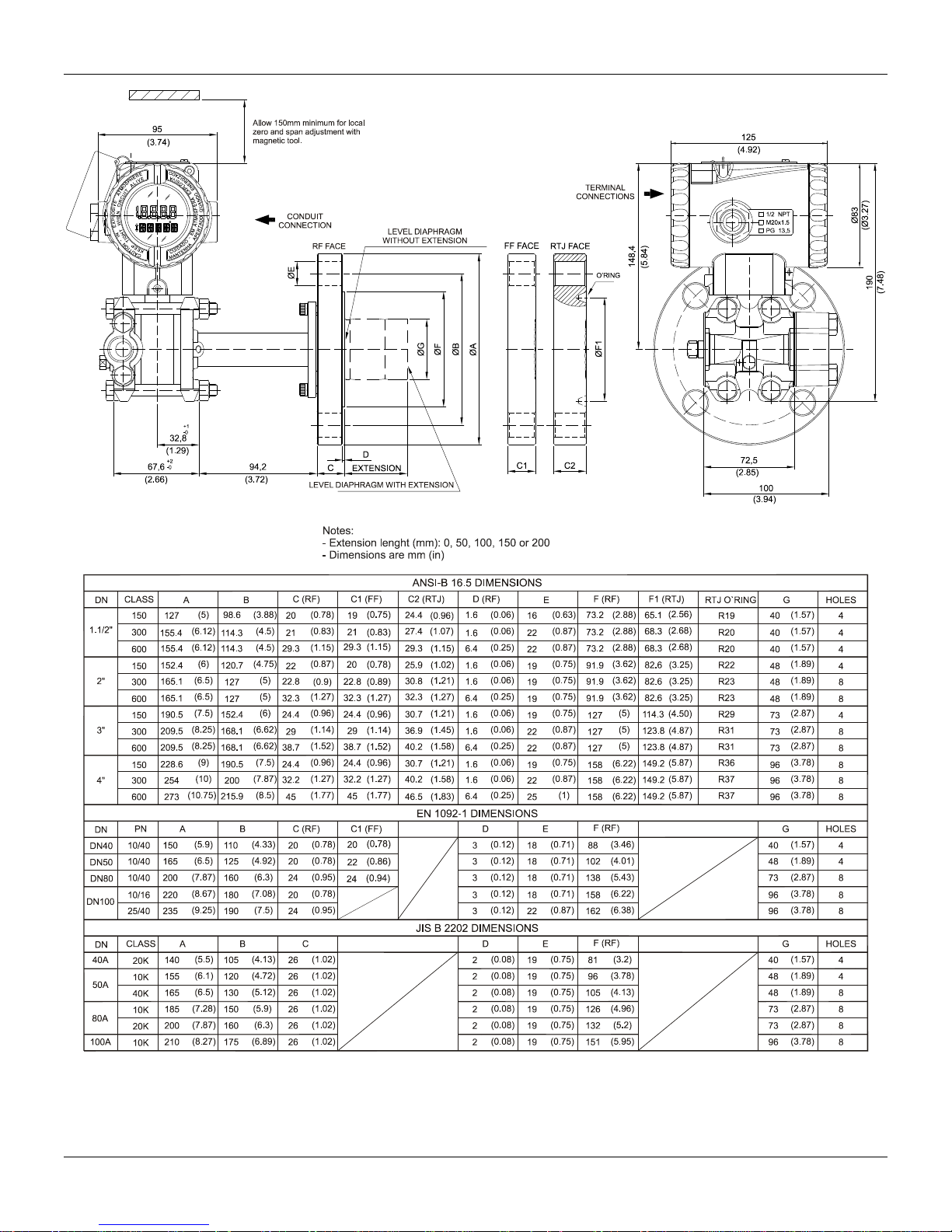
Figure 1.1 (a) – Dimensional Drawing and Mounting Position for the LD400 HART® – Differential Pressure, Flow, Gage,
Absolute and High Static Pressure Transmitter with Mounting Bracket
1.2
Installation
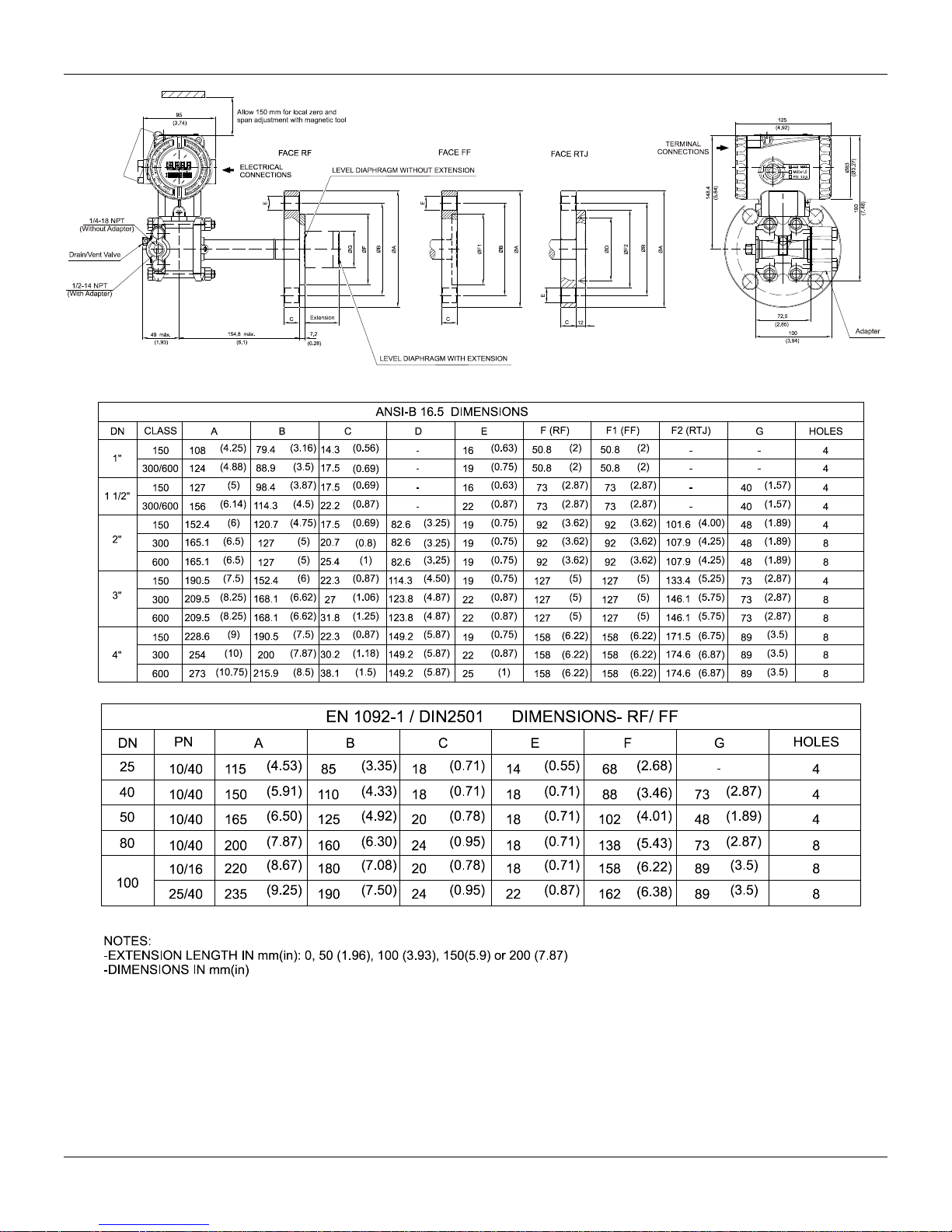
Figure 1.1 (b) – Dimensional Drawing and Mounting Position for the LD400 HART
Flange)
®
– Flanged Pressure Transmitter (Integral
1.3
LD400 HART® – Operation and Maintenance Instruction Manual
Figure 1.1 (c) – Dimensional Drawing and Mounting Position for the LD400 HART
1.4
Flange)
®
– Flanged Pressure Transmitter (Slip-on

Installation
Figure 1.1 (d) – Dimensional Drawing and Mounting Position for the LD400 HART
Housing
®
– Flanged Pressure Transmitter with
1.5

LD400 HART® – Operation and Maintenance Instruction Manual
Figure 1.1 (d) – Dimensional Drawing and Mounting Position for the LD400 HART
1.6
®
– Sanitary Transmitter with Extension

Installation
Figure 1.1 (e) – Dimensional Drawing and Mounting Position for the LD400 HART
®
– Sanitary Transmitter without Extension
1.7

LD400 HART® – Operation and Maintenance Instruction Manual
Process Fluid
Location of Taps
Location of LD400 HART® in Relation to the Taps
Gas
Top or Side
Above the taps.
Líquid
Side
Below the taps or at the piping centerline.
Steam
Side
Below the taps using Sealing (condensate) Pots.
NOTE
For liquids, condensates, wet vapors and gases the impulse lines must be bent on the ratio 1:10 to
prevent bubbles from accumulating.
GAS
LIQUID
STEAM
(See Section 6 –spa re pa rts for mou nting brackets availabl e)
Figure 1.2 – Drawing of LD400 HART
Some examples of installation, illustrating the transmitter position in relation to the taps, are shown
in Figure 1.3. The pressure taps location and the relative positions of the transmitter are indicated in
Table 1.1.
MOUNTING ON THE PANEL OR WALL
®
Mounted on the Panel or Wall
Table 1.1 – Location of Pressure Taps
Figure 1.3 – Position of the Transmitter and Taps
1.8

Installation
DIAPHRAGM SENSOR
SENSOR IN THE VERTICAL POSITION
SENSOR IN THE HORIZONTAL POSITION
HEAD OF THE FLUID
DIAPHRAGM SENSOR
NOTE
The transmitters are calibrated in the vertical position and a different mounting position displaces
the zero point. Consequently, the indicator will indicate a different value from the applied pressure.
l assembly position and its performance, when the transmitter is in its final position. When the
For fiscal measuring and custody transference, use a safety seal on the LD400 HART® , as shown
below.
Figure 1.4 – Safety Seal and Custody Transference
When the sensor is in the horizontal position, the fluid weight pushes the diaphragm down and then
the lower pressure trim must be applied. See Figure 1.5.
Figure 1.5 – Position of Sensor
In these conditions, it is recommended to do the zero pressure trim. The zero trim compensates the
fina
zero trim is executed, make sure the equalization valve is open and the wet leg levels are correct.
For the absolute pressure transmitter, the assembly effects correction should be done using the
Lower trim, due to the fact that the absolute zero is the reference for these transmitters, so there is
no need for a zero value for the Lower trim.
1.9

LD400 HART® – Operation and Maintenance Instruction Manual
COVER
LOCKING
SCREW
HOUSING ROTATION
SET SCREW
NOTE
To prevent humidity entering, the electric housing and the sensor joint must have a minimum of 6
fully engaged threads. The provided joint allows 1 extra turn to adjust the position of the display
window by rotating the housing clockwise. If the thread reaches the end before the desired
have a stopper that restricts housing rotation to one turn. See Section 6, Figure 6.2.
NOTE
rotate the flange. Do not remove the screw, according to a tag in the transmitter. See Figure 1.1
(a).
COVER
LOCKING
SCREW
Electronic Housing
The electronic housing can be rotated to adjust the digital display on a better position. To rotate it,
loose the Housing Rotation Set Screw, see Figure 1.6.
Wiring
Figure 1.6 – Cover Locking and Housing Rotating Set Screw
position, then rotate the housing counterclockwise, but not more than one thread turn. Transmitters
The display can also be rotated from 90º to 90º, for a better visualization. For more details on the
several display positions, see Secti on 6 – Figure 6. 4.
The process flange on the level transmitter may be rotated ± 45º. Just loosen the two screws and
To access the wiring block, loosen the cover locking screw to release the cover. See Figure 1.7.
Figure 1.7 – Terminal Connection Side
The terminal block has screws that fit fork or eye type terminals. See Figure 1.8.
1.10

Installation
NOTE
The cover must be tighten with at least 8 turns to avoid the penetration of humidity or corrosive
gases. The cover must be tighten until it touches the housing. Then, tighten more 1/3 turn (120°) to
guarantee the sealing. Lock the covers using the locking screw.
The signal cables passage to the terminal block may be done through one of the housing openings
and may be connected to a conduit or cable clamp.
The unused cable entries should be plugged and sealed accordingly to avoid humidity entering,
which can cause the loss of the product’s warranty. If the area is hazardous, use the required
stopper. This manual has an order code for this type of stopper. See Maintenance section.
COMUNICATIONS
TERMINALS
TEST
TERMINALS
GROUND TERMINAL
NOTE
The external ground was designed to accept wiring up to 10 mm² section (S=12 mm²). Use a
heavy duty conductor, at least Ø 1,6mm²/15 AWG.
Test and Communication terminals allow, respectively, to measure the current in the 4 - 20 mA loop,
without opening the circuit, and also to communicate with the transmitter. The “Test Terminals” must
be used to measure the current. The “COMM” terminal must be used for HART
®
communication.
The terminal block has screws where fork or ring-type terminals can be fastened. See Figure 1.8.
For convenience there are three ground terminals: one inside the cover and two external, located
close to the conduit inlets.
Figura 1.8 – LD400 HART® Terminal Block
The LD400 HART® terminal block was developed to allow signal connections regardless their
polarity.
Use of twisted pair (22 AWG or greater than) cables is recommended. For sites with high
electromagnetic levels (EMI above 10 V/m) shield conductors are recommended.
Avoid routing signal wiring near to power cables or switching equipment.
The duct threads must be sealed according to the hazardous area standards (see Installation in
Hazardous Locations page 1.15).
The unused passage opening must be sealed with stopper and seal as per the area requirements to
avoid humidity penetration. See Figure 1.9.
1.11

LD400 HART® – Operation and Maintenance Instruction Manual
NOTE
Typical Installati on for HART® Protocol
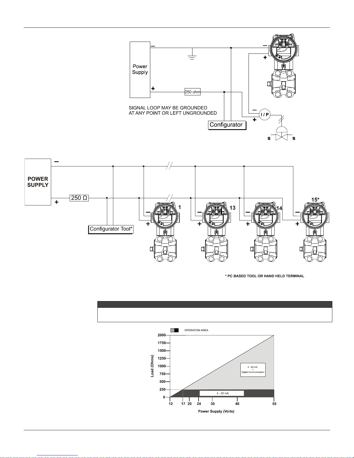
Figures 1.10 and 1.11 show LD400 HART® wiring diagrams to work as transmitter and controller,
respectively.
Figure 1.12 shows the LD400 HART
maximum of 15 transmitters can be connected on the same line and that they should be connected
in parallel. Take care to the power supply as well, when many transmitters are connected on the
same line. The current through the 250 Ω resistor will be high causing a high voltage drop.
Therefore make sure that the power supply voltage is sufficient.
For HART® transmitters to operate in multidrop mode each transmitter must be configured with a
different identity Device ID. In addition, if the transmitter identification mode on the loop is done
through the Command 0 address, the HART
the (Command 11) Tag the Tags must be similar.
The Handheld Terminal can be connected to the communication terminals of the transmitter or at
any point of the signal line by using the alligator clips. It is also recommended to ground the shield of
shielded cables at only one end. The ungrounded end must be carefully isolated. On multidrop
connections, the circuit loop integrity must be assured, with special care to prevent short-circuit
between the circuit loop and the housing.
Figure 1.9 – Eletroduct Thead Seal
®
wiring diagrams to work in the multidrop network. Note that a
®
address must also be different. If it is done through
1.12
Figure 1.10 – Wiring Diagram for the LD400 HART® Working as a Transmitter
Installation
NOTE
Make sure that the transmitter is operating within the operating area as shown on the load curve
Only
Figure 1.11 – Wiring Diagram for the LD400 HART
Figure 1.12 – Wiring Diagram for the LD400 HART
®
Working as a Controller
®
in Multidrop Configuration
(Figure 1.13). Communication requires a minimum load of 250 Ohm and voltage equal to 17 Vdc.
Figure 1.13 – Load Curve
1.13

LD400 HART® – Operation and Maintenance Instruction Manual
WARNING
Explosions could result in death or serious injury, besides financial damage. Installation of this
transmitter in explosive areas must be carried out in accordance with the local standards and the
protection type adopted. Before continuing the installation make sure the certificate parameters are
in accordance with the classified area where the equipment will be installed.
The instrument modification or parts replacement supplied by other than authorized representative
of Smar is prohibited and will void the certification.
The transmitters are marked with options of the protection type. The certification is valid only when
the protection type is indicated by the user. Once a particular type of protection is selected, any
other type of protection can not be used.
The electronic housing and the sensor installed in hazardous areas must have a minimum of 6 fully
engaged threads. Lock the housing using the locking screw (Figure 1.6).
The cover must be tighten with at least 8 turns to avoid the penetration of humidity or corrosive
gases. The cover must be tighten until it touches the housing. Then, tighten more 1/3 turn (120) to
guarantee the sealing. Lock the covers using the locking screw (Figure 1.7).
Consult the Appendix A for further information about certification.
WARNING
Only use Explosion Proof/Flameproof certified Plugs, Adapters and Cable glands.
In Explosion-Proof installations the cable entries must be connected or closed using metal cable
gland and metal blanking plug, both with at least IP66 and Ex-d certification.
The standard plugs provided by Smar are certified according to CEPEL certificate. If the plug
needs to be replaced, a certified plug must be used.
The electrical connection with NPT thread must use waterproofing sealant. A non-hardening
silicone sealant is recommended.
For NEMKO ATEX certificate please to follow the installation guidelines in hazardous locations
below:
Group II Category 2G, Ex d, Group IIC, Temperature Class T6, EPL Gb
U = 28VDC
Ambient Temperature: -20 to 60ºC for T6
Environmental Protection : IP65/67 or IP65W/67W
The electrical connection available are ½ - 14NPT and M20x1,5.
Cable entries must be connected or closed using metal cable gland and metal blanking plug, both
with at least IP66 and Ex-d certification or any appropriate ATEX approved metal cable gland and
metal blanking plug.
Do not remove the transmitter covers when power is ON.
WARNING
In hazardous zones with intrinsically safe or non-incendive requirements, the circuit entity
parameters and applicable installation procedures must be observed.
To protect the application the transmitter must be connected to a barrier. Match the parameters
between barrier and the equipment (Consider the cable parameters). Associated apparatus ground
bus shall be insulated from panels and mounting enclosures. Shield is optional. If used, be sure to
insulate the end not grounded. Cable capacitance and inductance plus Ci and Li must be smaller
than Co and Lo of the associated Apparatus.
For free access to the HART bus in the explosive environment, ensure the instruments in the loop
are installed in accordance with intrinsically safe or non-incendive field wiring practices. Use only
Ex HART communicator approved according to the type of protection Ex-i (IS) or Ex-n (NI).
It is not recommended to remove the transmitter cover when the power is ON.
Installation in Hazardous Locations
Explosion/Flame Proof
Intrinsically Safe
1.14

Section 2
d
A
C
ε
=
ε
( )
dd
A
CH∆+=
2/
.
ε
( )
dd
A
CL
∆−
⋅
=
2/
ε
FUNCTIONAL DESCRIPTION
Functional Descripti on – Sensor
The LD400 HART
pressure sensing elements, as shown in Figure 2.1
®
Smart Pressure Transmitters use capacitive sensors (capacitive cells) as
Figure 2.1 – Capacitive Cell
Where:
and P
P
1
CH = capacitance between the fixed plate on P
CL = capacitance between the fixed plate on the P
d = distance between CH and CL fixed plates.
∆d = sensing diaphragm's deflection due to the differential pressure ΔP = P1 - P2.
Knowing that the capacitance of a capacitor with flat, par all el plates may be ex pressed as a function
of plate area (A) and distance (d) between the plates as. See equation 1:
Where:
= dielectric constant of the medium between the capacitor's plates.
Should CH and CL be considered as capacitances of flat and parallel plates with identical areas,
when P1>P2 then:
and
are the pressures in chambers H and L.
2
(1)
(2)
1 side and the sensing diaphragm.
2 side and the sensing diaphragm.
(3)
2.1

LD400 HART® – Operation and Maintenance Instructi on M anu al
CHCL
CHCL+−
d
d
CHCL
CHCL
P
∆
=
+
−
=∆
2
P
H
P
L
HART
4-20 mA
HT3012
SENSOR
DIGITAL READING
INSULATOR
IN/OUT
OUTPUT
CONDITIONER
HART MODEM
D/A
CONVERTER
MATH
COPROCESSOR
DISPLAY
CONTROLLER
PROCESSING UNIT
RANGES
SPECIAL FUNCTIONS
PID
OUTPUT CONTROL
SERIAL COMUNICATION
PROTOCOL
ADVANCED DIAGNOSTIC
FIRMWARE UPDATE
HART
LOCAL ADJUSTMENTS
ZERO / SPAN
DIGITAL
DISPLAY
ELECTRONIC
CONVERTER
SENSOR
TEMPERATURE
ELECTRONIC
CONVERTER
PRESSURE
SENSOR
MAIN BOARD
However, should the differential pressure (ΔP) apply to the capacitive cell not deflect the sensing
diaphragm beyond d/4, it is possible to assume ΔP as proportional to Δd:
By developing the expression:
(4)
It follows that:
(5)
As the distance (d) between the fixed plates CH and CL is constant, it is possible to conclude that
the expression (CL - CH)/(CL + CH) is proportional to Δd and, therefore, to the differential pressure
to be measured.
Thus it is possible to conclude that the capacitive cell is a pressure sensor formed by two capacitors
whose capacitances vary according to the applied differential pressure.
Funcional Description – Hardware
Refer to the block diagram Figure 2.2. The function of each block is described below.
Figure 2.2 – LD400 HART® Block Diagram Hardware
Oscillator
This oscillator generates a frequency as a function of sensor capacitance.
Signal Isolator
The Control signals from the CPU are transferred through optical couplers, and the signal from the
oscillator is transferred through a transformer.
2.2
EEPROM
Another EEPROM is located within the sensor assembly. It contains data pertaining to the sensor's
characteristics at different pressures and temperatures. This characterization is done for each
sensor at the factory.
Temperature Sensor
Temperature Sensor used to compensate temperature variations.

Functional Description
(CPU) Central Processing Unit and PROM
The CPU is the intelligent portion of the transmitter, being responsible for the management and
operation of all other blocks, linearization and communication. The program is stored in an external
PROM. For temporary storage of data the CPU has an internal RAM. The data in the RAM is lost, if
the power is switched off, although the CPU also has an internal nonvolatile EEPROM where data
that must be retained is stored. Examples of such data are: calibration, configuration and
identification data.
D/A Converter
It converts the digital data from the CPU to an analog signal with 14-bits resolution.
Output
It controls the current in the line feeding the transmitters. It acts as a variable resistive load whose
value depends on the voltage from the D/A converter.
Modem
This system provides the data exchanged between the serve-master digital communications. The
transmitter demodulates information from the current line, and after treating it adequately, modulates
over the line the answer to be sent. A "1" is represented by 1200 Hz and "0" by 2200 Hz. The
frequency signal is symmetrical and does not affect the DC-level of the 4-20 mA signals.
Power Supply
Power must be supplied to the transmitter circuit using the signal line (2-wire system). The
transmitter quiescent consumption is 3.6 mA; during operation, consumption may be as high as 21
mA, depending on the measurement and sensor status. The LD400 HART
®
in the transmitter mode
shows failure indication at 3.6 mA if configured for low signal failure; at 21 mA, if configured for high
signal failure; 3.8 mA in the case of low saturation; 20.5 mA in the case of high saturation and
measurements proportional to the applied pressure in the range between 3.8 mA and 20.5 mA. 4
mA corresponds to 0% of the working range and 20 mA to100% of the working range.
Display Controller
It receives the data from the CPU and actives the LCD segments. It also activates the back plane
and the control signals for each segment.
Local Adjustment
Two switches on the main board are magnetically activated by inserting the magnetic screwdriver.
Without mechanical or electrical contact they cannot be activated. See figure 2.3.
Figure 2.3 – Local Adjustment
2.3

LD400 HART® – Operation and Maintenance Instructi on M anu al
Functional Descripti on – LD400 HART® Software
Refer to the block diagram Figure 2.3. The function of each block is described below.
Factory Characterization
The actual pressure from the capacitance and temperature readouts obtained from the sensor can
be calculated by using the factory characterization data stored in the sensor EEPROM.
Pressure Trim
The values obtained by Zero Pressure TRIM and Upper Pressure TRIM may correct here the
transmitter for long term drift or the shift in zero or upper pressure reading due to installation or over
pressure.
User Linearization
The characterization TRIM points P1 - P5 can be used to complement the transmitter original
characterization.
Digital Filter
The digital filter is a low pass filter with an adjustable time constant. It is used to smooth noisy
signals. The Damping value is the time required for the output reaching 63.2% for a step input of
100%.
This value (in seconds) may be freely configured by the user.
Engineering
The pressure value normalized it is converted for the engineering unit, considering the unit of
selected pressure and the Upper Range Limit (URL).
Calibration
The pressure value is calculated in percents taking in consideration the work range provided by the
Lower Range Value (LRV) and the Upper Range Value (URV).
Function
Depending on the application, the transmitter output or controller PV may have the following
characteristics according to the applied pressure: Linear (for pressure, different ial pre ssur e and lev el
measurement); Square-root (for flow measurement with differential pressure producers) and
Square-root of the Third and Fifth power (for flow measurements in open channels). The function is
selected with FUNCTION.
Block PID
The PID Block does the control having the Setpoint (SP) and the Process Variable (PV) as input and
the Manipulated Value (MV) as output.
Block PID: SP - Setpoint
It is the desired value in the process variable when the controller is activated. The operator in the
\CONTR\INDIC option adjusts it.
Block PID: PID Algorithm
First, the error is calculated: PV-SP (DIRECT ACTION) or SP-PV (REVERSE ACTION), then the
MV (manipulated value) is calculated, according to the algorithm of the PID. The PID output signal
may follow a user-determi ned curv e, in up to 16 configurable points. If the table is enabled, there will
be a display indication with the F(X) character
Block PID: Auto/Manual
The Auto/Manual mode is configured in CONTR/INDIC. With the PID in Manual, the MV can be
adjusted by the user in the LOW LIMIT to HIGH LIMIT range in the CONTR/LIM-SEG option. The
POWER-ON option is used here to determine in which mode the controller should be upon powering
it on.
Block PID: Limits
This block makes sure that the MV does not go beyond its minimum and maximum limits as
established by the HIGH-LIMIT and LOW-LIMIT. It also makes sure that the Rate-of-Change does
not exceed the value set in OUT-CHG/S.
2.4

Functional Description
Block PID: Bumpless A/M
On the Manual mode, the PID algoritm uses the output values as a compensation to its proportional
action so that the Manual to Automatic transition do not occur abruptly . Therefore, even if the
transition occurs in the presence of a percent ERROR., the proportional action is nullified and the
output is adjusted softly according to the integral action.
Block PID: Points Table PID
This block relates the output (4-20 mA or Process Variable) to the input (applied pressure)
according to a look-up table from 2 to 16 points. The output is calculated by the interpolation of
these points. The points are given in the function "TABLE POINTS" in percent of the range (X
in percent of the output (Y
i). It may be used to linearize, e.g., a level measurement to volume or
i) and
mass. In flow measurement it can be used to correct varying Reynolds numbers.
Output
It calculates the current proportional to the process variable or manipulated variable to be
transmitted on the 4-20 mA output depending on the configuration in OP-MODE. This block also
contains the constant current function configured in OUTPUT. The output is physically limited to 3.6
to 21 mA.
Current Trim
The 4 mA TRIM and 20 mA TRIM adjustment is used to make the transmitter current comply with a
current standard, should a deviation arise.
User Unit
It converts 0 and 100% of the process variable to the desired engineering unit readout available for
display and communication. It is used, e.g., to get a volume or flow indication from a level or
differential pressure measurement, respectively. A unit for the variable can also be selected.
Totalization
Used for flow application to totalize the accumulated flow since the last reset, the last reset, getting
the volume or mass transferred. In the lack of power, the totalized value is saved and continues
totalizing after its re-establishment.
Display
The two indications configured in the DISPLAY can be alternated.
2.5

LD400 HART® – Operation and Maintenance Instructi on M anu al
Figure 2.4 – LD400 HART
2.6
®
– Software Block Diagram
LD400 HART

M
A
Fix
F(t)
PID
SP
F(x)
35
PV
min
3 5
INDICATES THAT TOT ALIZATION
IS DISPLAYED
INDICATES ACTIVE
TABLE FUNCTION
* PID IS OPTIONAL
INDICATES ACTIVE
MULTIDROP MODE
INDICATES ACTIVE FUNCTION
VARIABLE FIELD
UNIT PERCENT
UNIT MINUTES
UNIT AND FUNCTION FIELD
UNIT AND FUNCTION FIELD
VARIABLE IS NOW DISPLAYED
x x x
INDICATES TRANSMITTER
IN PID MODE*
INDICATES ACTIVE
CONSTANT OUTPUT MODE
INDICATES CONTROLLER
IN AUTOMATIC*
INDICATES CONTROLLER
IN MANUAL*
INDICATES POSSIBILITY
TO ADJUST / CHANGE
VARIABLE / MODE
INDICATES THAT
THE SETPOINT
IS NOW DISPLAYED
Functional Descripti on - Display (LCD)
The local indicator is able to display three variables, which are user-selected. When multiples
variables are chosen, the display will alternate between both with an interval of 3 seconds.
The liquid crystal display includes a field with 4 ½ numeric digits, a field with 5 alphanumeric digits
and an information field, as shown on Figure 2.4 e 2.5.
When the totalization is displayed, the most significant part appears in the unit and function field
(upper) and the least significant part in the variable field (lower). See Total Value in Section 3.
Functional Description
Monitoring
During normal operation, the LD400 HART® is in the monitoring mode. In this mode, indication
alternates between the three variables (LCD_1, LCD_2, LCD_3) as configured by the user. See
Figure 2.6.
The display indicates engineering units, values and parameters simultaneously with most status
indicators.
Figure 2.4 – Display for LD400 HART
®
Figure 2.5 – Display for LD400 HART
®
SIS
2.7

LD400 HART® – Operation and Maintenance Instructi on M anu al
INDICATOR
Numeric
Alphanumeric
Maintenance)
CH / CL alternating with
current value
Transmitter failed on initialization (sensor memory failure or
Figure 2.6 – Typical Monitoring Mode Display Showing PV, in this case 25.00 mmH
The monitoring mode is interruped when the user applies the complete local adjustment.
The LD400 HART
®
display may also exhibit messages and errors. A few examples of these
messages are found on Table 2.1. For a complete list, see Section 6 – Maintenance.
Version LD400 HART and Version
Variable Value SAT / Unit
Sfail / Unit Failure on one sensor side or on both.
Current Value SFail / mA
Table 2.1 – Messages Displayed
PV
20
DESCRIPTION
The LD400 HART
®
is initialized after feeding.
Output current saturated on 3.8 or 20.5 mA. (see section 5 –
disconnected).
2.8

Section 3
Functional Specifications
Process Fluid
Liquid, gas or steam.
Output and Communication
Protocol
Two-wire, 4 - 20 mA controlled according to NAMUR NE43 specification, with superimposed digital communication
(HART
®
Protocol).
Power Supply
12 - 55 Vdc.
Input without polarization, with protection for transient suppressor and complemented by a lightning arrester.
Insulation of housing larger than 10 GΩ.
Transient Suppressor
V
max
= 65 Vp; Differential mode - bi-directional; Low current leak and capacitance;
meets the standards: IEEE61000-4-4 and IEEE61000-4-5;
Less than 5 ns response time.
Lightning Arrester
V = 1000 Vdc; Discharge current peak = 10 kA; Nominal current = 10 A/s;
Commom mode - low leak current and capacitance.
Indicator
4 1/2 -digit numerical and 5-character alphanumerical LCD indicator (optional).
Function and status icon.
Hazardous Area
Certifications
Explosion proof, intrinsically safe and increased safety (CEPEL)
Explosion proof (NEMKO)
Intrinsically safe (EXAM)
Explosion proof, intrinsically safe and dust ignition proof (FM) (Pending)
European
Directive
Information
Authorized representative in European Community
Smar Gmbh-Rheingaustrasse 9-55545 Bad Kreuzanach
ATEX Directive 94/9/EC - “Electrical equipment and protective system intended for use in potential
explosive atmospheres”
The EC-Type Examination Certificate had been released by Nemko AS (CE0470) and/or DEKRA EXAM GmbH
(CE0158), according to European Standards.
The certification body for Production Quality Assurance Notification (QAN) and IECEx Quality Assessment Report
(QAR) is Nemko AS (CE0470).
LVD Directive 2006/95/EC - “Electrical Equipment designed for use within certain voltage limits”
According the LVD directive Annex II, electrical equipment for use in an explosive atmosphere is outside the scope
of this directive.
According to IEC standard: IEC61010-1:2010 - Safety requirements for electrical equipment for measurement,
control, and laboratory use - Part 1: General requirements.
PED Directive 97/23/EC - “Pressure Equipment Directive”
The product is in compliance with Article 3 paragraph 3 of the Pressure Equipment Directve 97/23/EC and was
designed and manufactured in accordance with Sound Engineering Practice. The equipment cannot bear the CE
marking related to PED compliance. However, the product bear the CE marking to indicate compliance with other
applicable European Community directives.
EMC Directive 2004/108/EC - “Electromagnetic Compatibility”
The equipment is in compliance with the directive and EMC test was performed according to IEC standards:
IEC61326-1:2005 and IEC61326-2-3:2006.
To comply with the EMC directive the installation must follow these special conditions:
Use shielded, twisted-pair cable for powering the instrument and signal wiring.
Keep the shield insulated at the instrument side, connecting the other one to the ground.
The EC declarations of conformity for all applicable European directives for this product can be found at
www.smar.com.
Zero and Span
Adjustments
No interactive, via digital communication.
Jumper local adjustment with three positions: simple, disable, and complete.
TECHNICAL CHARACTERISTICS
3.1

LD400 HART® – Operation and Maintenance Instruction Manual
Functional Specifications
Load Limitation
Only
Failure Alarm
(Diagnostics)
Detailed diagnostics via HART® communicator.
Sensor failure and overpressure indication.
In case of sensor or circuit failure, the self-diagnostics drives the output to 3.6 or 21.0 mA, according to the user's
choice and NAMUR NE43 specification. Detailed diagnostic through HART
®
communication.
Temperature Limits
Ambient: -40 a 85 oC (-40 a 185 °F)
Process: -40 a 100 oC (-40 a 212 °F) (Silicon Oil)
-40 a 85 oC (-40 a 185 °F) (Inert Halocarbon Oil)
0 a 85 oC ( 32 a 185 °F) (Inert Fluorolube Oil)
-20 a 85 oC ( -4 a 185 °F) (Inert Krytox and Fomblim Oil)
-25 a 100 oC (-13 a 212 °F) (Viton O´Ring)
-40 a 150 oC (-40 a 302 °F) (Level Model)
Storage: -40 a 100 oC (-40 a 212 °F)
Digital Display: -20 a 80 oC ( -4 a 176 °F)
-40 a 85 oC (-40 a 185 °F) (Without damange)
Turn-on Time
Performs within specifications in less than 3 seconds after power is applied to the transmitter.
Configuration
By digital communication (HART® protocol) using the configuration software CONF401, DDCON 100 (for windows),
or HPC401 (for Palms). It can also be configured using DD and FDT/DTM tools, and can be partially configured
through local adjustment.
In order to keep the equipment configuration safe, the LD400 HART® has two kinds of write protection in its
memory. One is via software and the other a hardware mechanism selected by a key with priority over the
software.
Volumetric Displacement
Less than 0.15 cm3 (0.01 in3).
Overpressure and
Static Pressure
Limits (MWP – Maximum
Working Pressure)
From 3.45 kPa abs. (0.5 psia) to:
0.5 MPa (72.52 psi) for range 0
8 MPa (1150 psi) for range 1
16 MPa (2300 psi) for range 2, 3 e 4
32 MPa (4600 psi) for models H e A5
40 MPa (5800 psi) for model M5
52 MPa (7500 psi) for models M6 e A6
Flange Test Pressure: 68.95 MPa (10000 psi)
Overpressures above will not damage the transmitter, but a new calibration may be necessary.
WARNING
It is described here only the maximum pressures of the materials referenced in each rule,
it can not be manufactured on request.
Temperatures above 150 ° C are not available in standard models.
3.2
Functional Specifications
Overpressure and
Static Pressure
Limits (MWP – Maximum
Working Pressure)
(continuation)
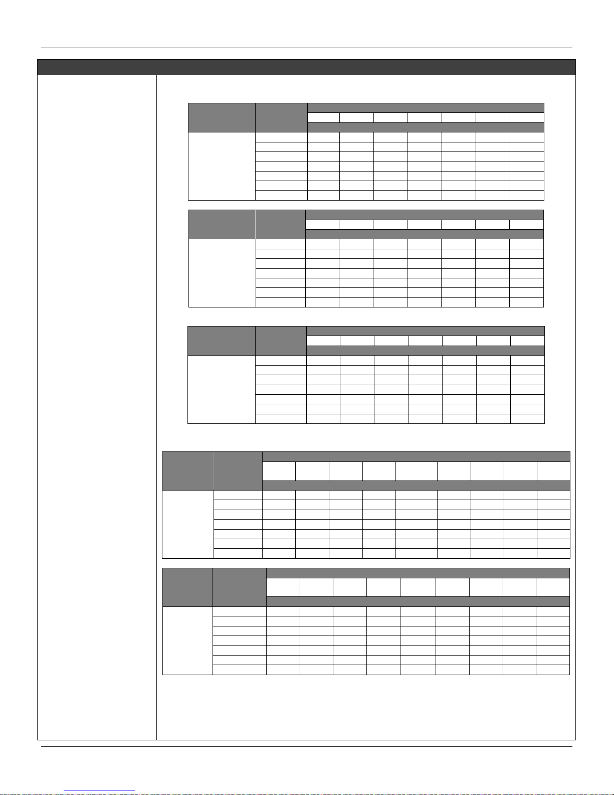
PRESSURES TABLE FOR SEAL AND LEVEL FLANGES DIN EN 1092-1 2008 STANDARD
Material
Group
Pressure
Class
Maximum Temperature Allowed
RT
100
150
200
250
300
350
Maximum Pressure Allowed (bar)
10E0
AISI 304/304L
PN 16
16
13.7
12.3
11.2
10.4
9,6
9.2
PN 25
25
21.5
19.2
17.5
16.3
15.1
14.4
PN 40
40
34.4
30.8
28
26
24.1
23
PN 63
63
63
57.3
53.1
50.1
46.8
45
PN 100
100
86.1
77.1
70
65.2
60.4
57.6
PN 160
160
137.9
123.4
112
104.3
96.7
92.1
PN 250
250
215.4
192.8
175
163
151.1
144
Material
Group
Pressure
Class
Maximum Temperature Allowed
RT
100
150
200
250
300
350
Maximum Pressure Allowed (bar)
14E0
AISI 316/316L
PN 16
16
16
14.5
13.4
12.7
11.8
11.4
PN 25
25
25
22.7
21
19.8
18.5
17.8
PN 40
40
40
36.3
33.7
31.8
29.7
28.5
PN 63
63
63
57.3
53.1
50.1
46.8
45
PN 100
100
100
90.9
84.2
79.5
74.2
71.4
PN 160
160
160
145.5
134.8
127.2
118.8
114.2
PN 250
250
250
227.3
210.7
198.8
185.7
178.5
Material Group
Pressure
Class
Maximum Temperature Allowed
RT
100
150
200
250
300
350
Maximum Pressure Allowed (bar)
16E0
1.4410 Super
Duplex
1.4462
Duplex
PN 16
16
16
16
16
16 - -
PN 25
25
25
25
25
25 - -
PN 40
40
40
40
40
40 - -
PN 63
63
63
63
63
63 - -
PN 100
100
100
100
100
100 - -
PN 160
160
160
160
160
160 - -
PN 250
250
250
250
250
250 - -
PRESSURES TABLE FOR SEAL AND LEVEL FLANGES ASME B16.5 2009 STANDARD
Material
Group
Pressure
Class
Maximum Temperature Allowed
-29 to
38
50
100
150
200
250
300
325
350
Maximum Pressure Allowed (bar)
Hastelloy
C276
150
20
19.5
17.7
15.8
13.8
12.1
10.2
9.3
8.4
300
51.7
51.7
51.5
50.3
48.3
46.3
42.9
41.4
40.3
400
68.9
68.9
68.7
66.8
64.5
61.7
57
55
53.6
600
103.4
103.4
103
100.3
96.7
92.7
85.7
82.6
80.4
900
155.1
155.1
154.6
150.6
145
139
128.6
124
120.7
1500
258.6
258.6
257.6
250.8
241.7
231.8
214.4
206.6
201.1
2500
430.9
430.9
429.4
418.2
402.8
386.2
357.1
344.3
335.3
Material
Group
Pressure
Class
Maximum Temperature Allowed
-29 to
38
50
100
150
200
250
300
325
350
Maximum Pressure Allowed (bar)
S31803
Duplex
S32750
Super
Duplex
150
20
19.5
17.7
15.8
13.8
12.1
10.2
9.3
8.4
300
51.7
51.7
50.7
45.9
42.7
40.5
38.9
38.2
37.6
400
68.9
68.9
67.5
61.2
56.9
53.9
51.8
50.9
50.2
600
103.4
103.4
101.3
91.9
85.3
80.9
77.7
76.3
75.3
900
155.1
155.1
152
137.8
128
121.4
116.6
114.5
112.9
1500
258.6
258.6
253.3
229.6
213.3
202.3
194.3
190.8
188.2
2500
430.9
430.9
422.2
382.7
355.4
337.2
323.8
318
313.7
Technical Characteristics
3.3

LD400 HART® – Operation and Maintenance Instruction Manual
Functional Specifications
Overpressure and
Static Pressure
Limits (MWP – Maximum
Working Pressure)
(continuation)
Material
Group
Pressure
Class
Maximum Temperature Allowed
-29 to
38
50
100
150
200
250
300
325
350
Maximum Pressure Allowed (bar)
AISI316L
150
15.9
15.3
13.3
12
11.2
10.5
10
9.3
8.4
300
41.4
40
34.8
31.4
29.2
27.5
26.1
25.5
25.1
400
55.2
53.4
46.4
41.9
38.9
36.6
34.8
34
33.4
600
82.7
80
69.6
62.8
58.3
54.9
52.1
51
50.1
900
124.1
120.1
104.4
94.2
87.5
82.4
78.2
76.4
75.2
1500
206.8
200.1
173.9
157
145.8
137.3
130.3
127.4
125.4
2500
344.7
333.5
289.9
261.6
243
228.9
217.2
212.3
208.9
Material
Group
Pressure
Class
Maximum Temperature Allowed
-29 to
38
50
100
150
200
250
300
325
350
Maximum Pressure Allowed (bar)
AISI316
150
19
18.4
16.2
14.8
13.7
12.1
10.2
9.3
8.4
300
49.6
48.1
42.2
38.5
35.7
33.4
31.6
30.9
30.3
400
66.2
64.2
56.3
51.3
47.6
44.5
42.2
41.2
40.4
600
99.3
96.2
84.4
77
71.3
66.8
63.2
61.8
60.7
900
148.9
144.3
126.6
115.5
107
100.1
94.9
92.7
91
1500
248.2
240.6
211
192.5
178.3
166.9
158.1
154.4
151.6
2500
413.7
400.9
351.6
320.8
297.2
278.1
263.5
257.4
252.7
Material
Group
Pressure
Class
Maximum Temperature Allowed
-29 to
38
50
100
150
200
250
300
325
350
Maximum Pressure Allowed (bar)
AISI304
150
19
18,3
15,7
14,2
13,2
12,1
10,2
9,3
8,4
300
49,6
47,8
40,9
37
34,5
32,5
30,9
30,2
29,6
600
99,3
95,6
81,7
74
69
65
61,8
60,4
59,3
1500
248,2
239,1
204,3
185
172,4
162,4
154,6
151,1
148,1
2500
413,7
398,5
340,4
308,4
287,3
270,7
257,6
251,9
246,9
Humidity Limits
0 to 100% UR (Relative Humid).
Damping Adjustment
User configurable from 0 to 128 seconds (via digital communication).
Performance Specifications
Reference Conditions
Span starting at zero, temperature of 25°C (77°F), atmospheric pressure, power supply of 24 Vcc, silicone oil fill
fluid, isolating diaphragms in 316L SST and digital trim equal to lower and upper range values.
Accuracy
Standard Class:
For range 0 and gage or diferential model:
0.16 URL ≤ span ≤ URL: ± 0.1 % span
0.05 URL ≤ span < 0.16 URL: ± [0.0545 + 0.0073 URL/span ] % span
For range 1 and diferential or gage model:
0.16 URL ≤ span ≤ URL: ± 0.06% span
0.025 URL ≤ span < 0.16 URL: ± [0.0364 + 0.0038 URL/span] % span
For range 2, 3 or 4 and diferential, high static pressure or gage models:
0.16 URL ≤ span ≤ URL: ± 0.06% span
0.025 URL ≤ span < 0.16 URL: ± [0.0364 + 0.0038 URL/span] % span
0.005 URL ≤ span < 0.025 URL: ± [0.0015 + 0.0047 URL/span] % span
For range 5 and gage or high static pressure or any sanitary model:
0.16 URL ≤ span ≤ URL: ± 0.065 % span
0,025 URL ≤ span < 0.16 URL: ± [0.0326 + 0.0052 URL/span] % span
0.0083 URL ≤ span < 0.025 URL: ± [0.01 + 0.0058 URL/span] % span
For range 6 and gage model:
0,16 URL ≤ span ≤ URL: ± 0.08 % span
0.025 URL ≤ span < 0.16 URL: ± [0.0504 + 0.0047 URL/span] % span
0.0083 URL ≤ span < 0.025 URL: ± [0.005 + 0.0059 URL/span] % span
For range 1 and absolute model:
± [0.0667 + 0.0333 URL/span] % span
For range 2 and absolute model:
0.16 URL ≤ span ≤ URL: ± 0.08 % span
3.4

Technical Characteristics
Accuracy
0.05 URL ≤ span < 0.16 URL: ± [0.0482 + 0.0051 URL/span] % span
For range 3 or 4 and absolute model:
0.16 URL ≤ span ≤ URL: ± 0.065 % span
0.025 URL ≤ span < 0.16 URL: ± [0.0326 + 0.0052 URL/span] % span
0.0083 URL ≤ span < 0.025 URL: ± [0.005 + 0.0059 URL/span] % span
For range 5 and absolute model:
0.16 URL ≤ span ≤ URL: ± 0.075 % span
0.025 URL ≤ span < 0.16 URL: ± [0.0443 + 0.0049 URL/span] % span
0.0083 URL ≤ span < 0.025 URL: ± [0.001 + 0.006 URL/span] % span
For range 6 and absolute model or for range 2, 3, 4 or 5 and level model:
0.16 URL ≤ span ≤ URL: ± 0.08 % span
0.025 URL ≤ span < 0.16 URL: ± [0.0504 + 0.0047 URL/span] % span
0.0083 URL ≤ span < 0.025 URL: ± [0.005 + 0.0059 URL/span] % span
Performance High Class:
For range 0 and diferential or gage models:
0.16 URL ≤ span ≤ URL: ± 0.06% span
0.05 URL ≤ span < 0.16 URL: ± [0.0009 + 0.0095 URL/span ] % span
For range 1 and diferential or gage models:
0.16 URL ≤ span ≤ URL: ± 0.05 % span
0.025 URL ≤ span < 0.16 URL: ± [0.0262 + 0.0038 URL/span] % span
For ranges 2, 3 or 4 and diferential or gage models:
0.16 URL ≤ span ≤ URL: ± 0.045 % do span
0.025 URL ≤ span < 0.16 URL: ± [0.0209 + 0.0039 URL/span] % span
0.005 URL ≤ span < 0.025 URL: ± [0.0025 + 0.0043 URL/span] % span
For range 5 and gage model:
0.16 URL ≤ span ≤ URL: ± 0.055 % do span
0.025 URL ≤ span < 0.16 URL: ± [0.0263 + 0.0046 URL/span] % span
0.0083 URL ≤ span < 0.025 URL: ± [0.015 + 0.0049 URL/span] % span
For range 6 and gage model:
0.16 URL ≤ span ≤ URL: ± 0.075 % span
0.025 URL ≤ span < 0.16 URL: ± [0.0463 + 0.0046 URL/span] % span
0.0083 URL ≤ span < 0.025 URL: ± [0.005 + 0.0056 URL/span] % span
Stability
For ranges 2, 3, 4, 5 or 6:
Performance High Class: ± 0.2% do URL per 12 years
Standard Class: ± 0.15% URL per 7 years
At 20 ºC temperature change and up to 7 MPa (1000 psi) of static pressure.
For range 1:
Performance High Class: ± 0.3% do URL per 12 years
Standard Class: ± 0.3% do URL per 7 years
At 20 ºC temperature change and up to 3.5 MPa (500 psi) of static pressure.
For range 0:
Performance High Class: ± 0.4% do URL per 12 years
Standard Class: ± 0.4% do URL per 7 years
At 20 ºC temperature change and up to 100 kPa (14.5 psi) of static pressure.
Note: Installation complying with the best process practices and adequacy may be generated (hydrogen migration).
Temperature Effect
For any model range 2, 3, 4, 5 or 6 , except level or sanitary models:
0.1 URL ≤ span ≤ URL: ± [0.0205% URL + 0.0795% span] per 20 ºC (68 ºF)
span < 0.1 URL: ± [0.021% URL + 0.075% span] per 20 ºC (68 ºF)
For any model range 1:
0.1 URL ≤ span ≤ URL: ± [0.05% URL + 0.08% span] per 20 ºC (68 ºF)
span < 0.1 URL: ± [0.055% URL + 0.03% span] per 20 ºC (68 ºF)
For any model range 0:
0.1 URL ≤ span ≤ URL: ± [0.1% URL + 0.1% span] por 20 ºC (68 ºF)
span < 0.1 URL: ± [0.105% URL + 0.05% span] por 20 ºC (68 ºF)
For any level or sanitary model:
6 mmH2O per 20 ºC for flange 4" and DN100
17 mmH2O per 20 ºC for flange 3" and DN80
Consult for other flange dimensions and fill fluid.
3.5

LD400 HART® – Operation and Maintenance Instruction Manual
Static Pressure Effect
Zero Error:
For ranges 5*: ± 0.05% URL (± 0.1% for Tantalum diaphragm) per 7 MPa (1000 psi)
For ranges 2, 3 or 4*: ±0.025% URL (± 0.1% for Tantalum diaphragm) per 7 MPa (1000 psi)
For range 1: ± 0.05% URL per 1.7 MPa (250 psi)
For range 0: ± 0.1% URL por 0.5 MPa (73 psi)
For any level or sanitary models:: ± 0.1% URL per 3.5 MPa (500 psi)
The zero error is a systematic error that can be eliminated by calibrating at the operating static pressure.
Span Error:
For ranges 2,3,4 ou 5*: correctable to ± 0.1% of reading per 7MPa (1000 psi)
For range 1: correctable to ± 0.1% of reading per 1.7 MPa (250 psi)
For range 0: correctable to ± 0.2% of reading per 0.5 MPa (72 psi)
For level or sanitary models: correctable to ± 0.1% of reading per 3.5 MPa (500 psi)
* Except level or sanitary model.
Power Supply Effect
± 0.005% of calibrated span per volt
Mounting Position
Effect
Zero shift of up to 250 Pa (1 inH2O) which can be calibrated out.
No span effect.
Electromagnetic
Interference Effect
Approved according to IEC61326-1:2006, IEC61326-2-3:2006, IEC61000-6-4:2006, IEC61000-6-2:2005.
Vibration Effect
All models: URL ±0.1% in plants with high vibration levels or piping with too much vibration, according to the
following specification by IEC 60770-1: 10-60 Hz, 0.21 mm peak displacement standard / 60-2000 Hz, 29.4 m/s2
acceleration.
NOTE
URL = Upper Range Limit
LRL = Low Range Limit
Physical Specifications
ElectricalConnection
½ - 14 NPT
¾ - 14 NPT (with 316 SST adapter for 1/2 - 14 NPT)
¾ - 14 BSP (with 316 SST adapter for 1/2 - 14 NPT)
½ - 14 BSP (with 316 SST adapter for 1/2 - 14 NPT)
M20 X 1.5
PG 13.5 DIN
Process Connection
¼ - 18 NPT ou ½ -14 NPT (with adapter)
For level models or more information, see Ordering Code.
Wetted Parts
Isolating Diaphragms:
316L SST, Hastelloy C276, Monel 400 or Tantalum
Drain/Vent Valves and Plug:
316 SST, Hastelloy C276 or Monel 400
Flanges:
Plated Carbon Steel, 316 SST-CF8M (ASTM - A351), Hastelloy C276 - CW-12MW, (ASTM - A494) or Monel 400
O-Rings (For Flanges and Adapters):
Buna-N, Viton™ PTFE or Ethylene-Propylene.
The LD400 HART is available in NACE MR-01-75/ISO 15156 compliant materials.
Nonwetted Parts
Electronic Housing:
Injected aluminum with polyester painting, epoxy painting or 316 SST - CF8M (ASTM - A351) housing.
Complies with NEMA 4X/6P, IP66/68* or IP66W/68W**.
* IP68 was performed at 1 bar for 24 hours.
** Additional letter "W" was performed in a saturated solution of NaCI 5% w/w at 35◦C for a time of 200 h.
For any other situation, please consult Smar.
Blank Flange:
When flange adapter and Drain/Vent material is carbon steel, blank flange is in carbon steel, otherwise blank
flange is in 316 SST - CF8M (ASTM - A351)
Level Flange (LD400L):
316 L SST
Fill Fluid:
Silicone, Fluorolube (Inert) , Krytox, Halocarbon 4.2 or Fomblim oils
Cover O-Rings:
Buna-N
Mounting Bracket:
Plated Carbon Steel or 316 SST
Accessories (bolts, nuts, washers and U-clamps) in Carbon Steel or 316 SST
Flange Bolts and Nuts:
Plated Carbon Steel, Grade 8 or 316 SST
For NACE applications: Carbon Steel ASTM A193B7M
3.6

Technical Characteristics
Identification Plate:
316 SST
Mounting
a) Flange mounted for Level models.
b) Optional universal mounting bracket for surface or vertical/horizontal 2"- pipe (DN 50).
c) Manifold Valve integrated to the transmitter.
d) Directly on piping for closely coupled transmitter/orifice flange combinations.
Approximate Weights
3.15 kg (7 lb): all models, except L models.
5.85 to 9.0 kg (13 lb to 20 lb): L models depending on the flanges, extension and materials.
Control Functions
Characteristics (Optional)
Control Block (PID) and Totalization (TOT)
NOTE: The PID block isn´t available for use in SIS Mode.
3.7

LD400 HART® – Operation and Maintenance Instruction Manual
MODEL
DIFERENTIAL PRESSURE, FLOW, GAGE, ABSOLUTE AND HIGH STATIC PRESSURE TRANSMITTER
LD400
Smart Pressure Transmitter
COD
Type
RANGE LIMITS
Turn Down
Min.
Max.
Unid. Min.
Max.
Unid. Max.
D0
D1
D2
D3
D4
M0
M1
M2
M3
M4
M5
M6
A0
A1
A2
A3
A4
A5
A6
H2
H3
H4
H5
Diferential (23)
Diferential and Flow
Diferential and Flow
Diferential and Flow
Diferential and Flow
-1
-5
-50
-250
-2500
1
5
50
250
2500
kPa
kPa
kPa
kPa
kPa
-10
-50
-500
-2500
-25
10
50
500
2500
25
mbar
mbar
mbar
mbar
bar
20
40
200
200
200
NOTE: The range can be
extended up to 0.75 LRL* and
1.2 URL* with small degradation
of accuracy.
*LRL = Lower Range Limit.
*URL = Upper Range Limit
Due to differences in
mechanical project, A1 range
has turn-down lower than A0
range.
Gage
Gage
Gage
Gage
Gage
Gage
Gage
-1
-5
-50
-100
-100
-0,1
-0,1
1
5
50
250
2500
25
40
kPa
kPa
kPa
kPa
kPa
MPa
MPa
-10
-50
-500
-1000
-1
-1
-1
10
50
500
2500
25
250
400
mbar
mbar
mbar
mbar
bar
bar
bar
20
40
200
200
200
120
120
Absolute
Absolute
Absolute
Absolute
Absolute
Absolute
Absolute
0
0
0
0
0
0
0
1
5
50
250
2500
25
40
kPa
kPa
kPa
kPa
kPa
MPa
MPa
0
0
0
0
0
0
0
7.5
37
500
2500
25
250
400
mmHga
mmHga
mbar
mbar
bar
bar
bar
20
4
20
120
120
120
120
Diferential – High Static Pressure
Diferential – High Static Pressure
Diferential – High Static Pressure
Diferential – High Static Pressure
-50
-250
-2500
-25
50
250
2500
25
kPa
kPa
kPa
MPa
-500
-2500
-25
-250
500
2500
25
-250
mbar
mbar
bar
bar
120
120
120
120
COD
Diaphragm Material and Fill Fluid
1
2
3
4
5
7
8
9
A
D
E
G
K
316L SST Óleo Silicone (9)
316L SST Inert (Fluorolube Oil) (2) (19)
Hastelloy C276 Silicone Oil (1) (9)
Hastelloy C276 Inert (Fluorolube Oil) (1) (2) (19)
Monel 400 Silicone Oil (1)(3)(9)
Tantalum Silicone Oil (3) (9)
Tantalum Inert (Fluorolube Oil) (2) (3) (19)
316L SST Fomblim Oil (12)
Monel 400 Fomblim Oil (1) (3)
316 L SST Inert (Krytox Oil) (12) (19)
Hastelloy C276 Inert (Krytox Oil) (1) (12) (19)
Tantalum Inert (Krytox Oil) (3) (19)
Monel 400 Inert (Krytox Oil) (1) (3) (19)
M
P
Q
R
S
I
J
L
T
U
V
W
X
Monel 400 Gold Plated Silicone Oil (1) (3) (9)
Monel 400 Gold Plated Inert (Krytox Oil) (1) (3) (19)
316 L SST Inert (Halocarbon 4.2 Oil) (19)
Hastelloy C276 Inert (Halocarbon 4.2 Oil) (19)
Tantalum Inert (Halocarbon 4.2 Oil) (3) (19)
316L SST, L.I. Gold Plated Silicone Oil (3) (9) (18)
316L SST, L.I. Gold Plated Inert (Fluorolube Oil) (3) (4) (18) (19)
316L SST, L.I. Gold Plated Inert (Krytox Oil) (3) (18) (19)
316L SST, L.I. Gold Plated Inert (Halocarbon 4.2 Oil) (3) (18) (19)
316L SST, L.I. Silicone Oil (3) (9) (18)
316L SST, L.I. Inert (Fluorolube Oil) (3) (4) (18) (19)
316L SST, L.I. Inert (Krytox Oil) (3) (18) (19)
316L SST, L.I. Inert (Halocarbon 4.2 Oil) (3) (18) (19)
Note: L.I. = integral sheet
COD
Performance Class
0
1
Default
High Performance (14)
COD
Communication Protocol
H HART® and 4 to 20 mA
COD
Security Option
0
1
Default– For use in mesurement and control
SIS - Safety Instrumented Systems (24)
COD
Flange(s), Adapter(s) and Drain/Vent Valves Material
0
P
H
I
F
M
1
2
3
Without Flanges, Adapters and Drain/Vent Valves
Carbon Steel with superficial treatmente (Stainless Steel Purge) (20)
Hastelloy C276 (CW-12MW, ASTM - A494) (1)
316 SST - CF8M (ASTM A351)
Monel 400 - Laminatged bar (for HF application) (1)
Monel 400 - Micro-casting (1)
316 SST - CF8M (ASTM A351) (Drain/Vent in Hastelloy C276) (1)
316 SST - CF8M (ASTM A351) Flange with PVDF (Kynar) Insert (5) (7) (11)
316 SST – CF8M (Drain/Vent and Plug in Monel) Nace Standard
COD
O´Ring Material
0
B
E
Without O´Ring
Buna-N
Etileno-Propileno
K
T
V
Kalrez (3)
Teflon
Viton
Nota: O´Rings are not available on the side with Remote Seals.
COD
Drain/Vent Position
0
A
D
U
Without Drain/Vent
Drain/Vent (Opposite to Process Connection)
Botton
Top
Note: For better drain/vent operation, vent valves are strongly
recommended.
Drain/Vent valve are not available on the sides with remote seals.
COD
Process Connections
0
1
2
3
5
9
B
D
F
H
Q
T
V
Z
1/4 - 18 NPT (Without Adapter)
1/2- 14 NPT (With Adapter)
CF 16 (Without Adapter)
Remote Seal (With Plug) (3) (8)
1/2 - 14 NPT Axial (with PVDF Insert PVDF) (5) (7) (16)
Remote Seal (Low Volume Flange) (3) (4) (8)
High Side: 1/2 - 14 NPT Low Side: Remote Seal (With Plug) (3) (10)
High Side: Remote Seal (With Plug) and Low Side: 1/2 14 NPT (3) (10)
High Side: 1/2 - 14 NPT and Low Side: Low volume flange for remote seal (3) (10)
High Side: Low volume flange for remote seal and Low Side: 1/2 - 14 NPT (3) (10)
8mm hole without thread. According to DIN 19213 (13)
1/2 - 14 BSP (With Adapter)
Manifold Valve Integrated to the Transmitter
User’s specification
COD
Special Aplications
0
1
Without special cleaning
Degrease Cleaning (Oxygen or Chlorine Service) (15)
LD400
-
D2 1 0 - H 0 - I B D 1
1
CONTINUE IN THE NEXT PAGE
Ordering Code
3.8

Technical Characteristics
LD400-D210-H0-IBD11
DIFERENTIAL PRESSURE, FLOW, GAGE, ABSOLUTE AND HIGH STATIC PRESSURE TRANSMITTER (CONTINUATION)
COD
Flanges Bolts and Nuts Material
P
I
C
H
A
Plated Carbon Steel (Default) (20)
316 SST
Carbon Steel (ASTM A193 B7M) (1) (20)
Hastelloy C276
Super Duplex Stainless Steel Nace MR0175 / MR0103 Compliant
COD
Flange thread for fixing accessories (adapters, manifolds, mounting brackets, etc)
0
1
2
7/16 UNF
M10 X 1.5
M12 X 1.75
COD
Local Indication
0
1
Without Indicator
With Digital Indicator
COD
Electrical Connections
0
1
2
3
A
B
Z
1/2 - 14 NPT (22)
3/4- 14 NPT (with 316 SST adapter for 1/2 - 14 NPT) (22)
3/4- 14 BSP (with 316 SST adapter for 1/2 - 14 NPT) (6)
1/2 - 14 BSP (with 316 SST adapter for 1/2 - 14 NPT) (6)
M20 X 1.5 (22)
PG 13.5 DIN (22)
User’s specification
COD
Blanket Plug
I
C
316 SST
Carbon Steel (Only available for ½” process connection) (20)
COD
Mounting Bracket for 2” Pipe or Surface Mounting
0
1
2
5
6
7
9
A
Z
Without Bracket
Carbon steel bracket and accessories (20)
316 SST bracket and accessories
L type, carbon steel bracket and accessories (20)
L type, 316 SST bracket and accessories
Carbon steel bracket. Accessories: 316 SST (20)
L Type, carbon steel bracket. Accessories: 316 SST (20)
Flat, 304 SST bracket and 316 SST accessories
User’s specification
COD
Housing Material (25) (26)
A
I
Aluminium (Default)
316 SST – CF8M (ASTM – A351)
J
B
316 SST - saline atmospheres (21)
Aluminium - saline atmospheres (21)
COD
Painting
0
8
9
C
Z
Gray Munsell N 6.5 Polyester
Without Painting (17)
Safety Blue Epoxy – Electrostatic Painting
Safety Blue Polyesters – Electrostatic Painting
Special Painting
COD
Certification Type for Hazardous Locations
N
I
E
D
Without Certification
Intrinsic Safety
Increased Safety
Explosion Proof
F
G
H
J
Non-incendive + Intrinsic Safety
Explosion Proof + Increased Safety
Intrinsic Safety + Explosion Proof + Increased Safety
Non-incendive + Intrinsic Safety + Dust
COD
Identification Plate for Hazardous Locations
0
1
2
Without Certification
FM (Pending)
NEMKO (ATEX)
5
7
CEPEL
EXAM
COD
Tag Plate
0
1
2
With tag, when specified (Default)
Blank
User’s specification
COD
HART® Configuration
**
LD400-D210-H0-
IBD11
- P 0 1 - 0 I 1 - A 0 N 0 0 /
**
TYPICAL MODEL NUMBER
Notes:
(1) Meets NACE MR – 01 – 75/ISO 15156 recommendations.
(2) Not available for absolute models nor vacuum applications.
(3) Not aplicable for ranges 0 and 1.
(4) Not applicable for vacuum service.
(5) Pressure maximum: 24 bar.
(6) Options not certified for use in hazardous locations.
(7) Drain/Vent not applicable.
(8) For Remote Seal only 316 SST CF8M (ASTM A351) flange is available
(thread 7/16 UNF).
(9) Silicone Oil is not recommended for Oxygen (O2) or Chlorine service.
(10) Only available for diferential pressure transmitter.
(11) O´Ring material must be of Viton or Kalrez.
(12) Not aplicable for ranges 0.
(13) Only available for pressure transmitters D4 or H4 and 7/16 UNF or M10 x
1.5 flange thread for fixing accessories.
(14) Only available for LD400D and LD400M.
(15) Degrease cleaning not available for carbon steel flanges.
(16) Only available for Flange with PVDF (Kynar) Insert.
(17) Not available for alumunium housing.
(18) Efective for hydogen migration processes.
(19) Inert Fluid: Oxygen Compatibility, safe for oxygen service.
(20) Not applicable for saline atmosphere.
(21) IPW/TYPEX was performed in a saturated solution of NaCI 5% w/w at 35◦C
for a time of 200 h.
(22) Certificate for use in Explosion Proof (CEPEL).
(23) The D0 range should not be used for flow measurement.
(24) SIL 1 and SIL 2 (non-redindant) and SIL 3 (redundant) applications.
(25) IPX8 tested in 10 meters of water column for 24 hours.
(26) Ingress Protection:
Product
CEPEL
NEMKO / EXAM
FM
LD400
IP66/68W
IP65/67W
Type4X/6P
** Fill out with HART® Optional Configuration (see page 3.14)
3.9

LD400 HART® – Operation and Maintenance Instruction Manual
MODEL
FLANGED PRESSURE TRANSMITTER
LD400
Smart Pressure Transmitter
COD
TYPE
RANGE LIMIT
Turn Down
Min
Max
Unidd
.
Min
Max
Unit Max
L2
L3
L4
L5
Level
Level
Level
Level
-50
-250
-2500
-25
50
250
2500
25
kPa
kPa
kPa
MPa
-500
-2500
-25
-250
500
2500
25
250
mbar
mbar
bar
bar
120
120
120
120
The range can be extended up to 0.75 LRL and 1.2 URL with small
degradation of accuracy. The upper range value must be limited to the
flange rating.
COD.
Diaphragm material and Fill Fluid (Low Side)
1
2
3
4
5
7
8
9
A
D
E
G
K
M
P
Q
R
S
I
J
L
T
U
V
W
X
316L SST Silicone Oil (2)
316L SST Inert (Fluorolube Oil) (3) (18)
Hastelloy C276 Silicone Oil (1) (2)
Hastelloy C276 Inert (Fluorolube Oil) (1) (3) (18)
Monel 400 Silicone Oil (1) (2)
Tantalum Silicone Oil (2)
Tantalum Inert (Fluorolube Oil) (3) (18)
316L SST Fomblim Oil
Monel 400 Fomblim Oil (1)
316 L SST Inert (Krytox Oil) (18)
Hastelloy C276 Inert (Krytox Oil) (1) (18)
Tantalum Inert (Krytox Oil) (18)
Monel 400 Inert (Krytox Oil) (1) (18)
Monel 400 Gold Plated Silicone Oil (1) (2)
Monel 400 Gold Plated Inert (Krytox Oil) (1) (18)
316L SST Inert (Halocarbon 4.2 Oil) (18)
Hastelloy C276 Inert (Halocarbon 4.2 Oil) (1) (18)
Tantalum Inert (Halocarbon 4.2 Oil) (18)
316L SST, L.I. Gold Plated Silicone Oil (2) (17)
316L SST, L.I. Gold Plated Inert (Fluorolube Oil) (3) (17) (18)
316L SST, L.I. Gold Plated Inert (Krytox Oil) (17) (18)
316L SST, L.I. Gold Plated Inert (Halocarbon 4.2 Oil) (17) (18)
316L SST, L.I. Silicone Oil (2) (17)
316L SST, L.I. Inert (Fluorolube Oil) (3) (17) (18)
316L SST, L.I.. Inert (Krytox Oil) (17) (18)
316L SST, L.I. Inert (Halocarbon 4.2 Oil) (17) (18)
COD.
Performance Class
0 Default
COD.
Communication Protocol
H HART® and 4 to 20 mA
COD.
Security Option
0
1
Default- For use in measurement and control
SIS - Safety Instrumented Systems (25)
COD.
Flange, Adapter and Drain/Vent Valves material
A
P
H
I
F
M
1
2
304L SST
Plated CS (Drain/Vent in Stainless Steel) (19)
Hastelloy C276 (CW-12MW, ASTM - A494) (1)
316 SST - CF8M (ASTM A351)
Monel 400 - Laminatged bar (Aplication in HF)
Monel 400 - Micro-casting (1)
316 SST - CF8M (ASTM A351) (Drain/Vent in Hastelloy C276) (1)
316 - CF8M (ASTM A351) Flange with PVDF (Kynar) Insert (3) (4) (5)
COD.
O’Ring Material
O
B
E
K
T
V
Without O´Ring
Buna-N
Ethylene - Propylene
Kalrez
Teflon
Viton
Note: O’rings are not available on the sides with remote seals.
COD.
Drain/Vent Position (Low Side)
0
A
D
U
Without Drain/Vent
Drain/Vent (Opposite to Process onnection)
Botton
Top
Note: For better Drain/Vent operation, vent valves are
strongly recommended.
Drain/Vent valve are not available on the sides with remote
seals.
COD.
Process Connection (Low Side)
0
1
3
5
9
T
Z
1/4 - 18 NPT (Without adapter)
1/2- 14 NPT (With adapter)
Remote Seal (With Plug) (7)
1/2- 14 NPT Axial with PVDF Insert (3) (4) (6)
Remote Seal (Low Volume Flange (3) (7)
1/2 - 14 BSP (With adapter)
User´s specifications
COD.
Special Aplications
0
1
2
Without Special Aplications
Degrease Cleaning (Oxygen or Chlorine Service) (11)
For vacuum aplications
COD.
Flanges Bolts and Nuts Material
P
I
C
H
Plated Carbon Steel (Default) (19)
316 SST
Carbon Steel (ASTM A193 B7M) (1) (19)
Hastelloy C276
COD.
Flange thread for fixing accessories (adapters, manifolds, mounting
brackets, etc)
0
1
2
7/16UNF (Default)
M10 X 1.5
M12 X 1.75
LD400 - L2 1 0 - H
0 - P B D 0 0 - P
0
CONTINUE IN THE NEXT PAGE
Note: L.I = Integral Steel
3.10

Technical Characteristics
LD400-L210-H0-PBD00-P0
FLANGED PRESSURE TRANSMITTER (CONTINUATION)
COD.
Process Connection (High Side)
U
V
W
O
P
Q
9
A
B
1
2
C
3
4
D
5
R
E
6
7
8
H
F
G
S
L
T
Z
1" 150 # (ANSI B16.5) (28)
1" 300 # (ANSI B16.5) (28)
1" 600 # (ANSI B16.5) (28)
1 1/2" 150 # (ANSI B16.5)
1 1/2" 300 # (ANSI B16.5)
1 1/2" 600 # (ANSI B16.5)
2" 150 # (ANSI B16.5)
2" 300 # (ANSI B16.5)
2" 600 # (ANSI B16.5)
3" 150 # (ANSI B16.5)
3" 300 # (ANSI B16.5)
3" 600 # (ANSI B16.5)
4" 150 # (ANSI B16.5)
4" 300 # (ANSI B16.5)
4" 600 # (ANSI B16.5)
DN 25 PN10/40 (DIN EN 1092-1) (28)
DN 40 PN10/40 (DIN EN 1092-1)
DN 50 PN 10/40 (DIN EN 1092-1)
DN 80 PN 10/40 (DIN EN 1092-1)
DN 100 PN 10/16 (DIN EN 1092-1)
DN 100 PN 25/40 (DIN EN 1092-1)
10K 100A (JIS 2202) (22)
10K 50A (JIS 2202) (22)
10K 80A (JIS 2202) (22)
20K 40A (JIS 2202) (22)
20K 80A (JIS 2202) (22)
40K 50A (JIS2202) (22)
User´s specifications
COD.
Type and Flange Material (High Side)
I
H
316L SST (Integral Flange)
Hastelloy C276 (Integral Flange)
J
K
304 SST (Slip-on Flange)
316 SST (Slip-on Flange)
L
Z
Carbon Steel (Slip-on Flange)
User’s specification
COD.
Flange Facing Finish
0
1
2
3
4
5
6
Raised Face – RF (Default))
Flat Face – FF (14)
Ring Joint Face – RTJ (Only available for ANSI standard flange) (13)
Small Tongue Face (14) (15)
Small Grooved Face (14) (15)
Large Tongue Face (14) (15)
Large Grooved Face (14) (15)
COD.
Extension Length
0
1
2
3
4
Z
0 mm (0")
50 mm (2")
100 mm (4")
150 mm (6")
200 mm (8")
User´s specifications
Note: Extension Material 316L SST
COD.
Diaphragm Material (Tap Level)
A
L
H
M
T
X
1
2
3
304L SST
316 L SST
Hastelloy C276
Monel 400
Tantalum (10)
Titanium (10)
316L SST with Teflon Lining (For 2”and 3”)
316L SST Gold plated
Tantalum with Teflon Lining
COD.
Fill Fluid (Tap Level)
1
2
3
4
N
T
Z
Silicone DC-200/20 Oil
Inert (Fluorolube MO-10 Oil) (8) (18)
Silicone DC704 Oil
Inert (Krytox Oil) (18)
Neobee M20 Propylene Glycol Oil
Syltherm 800 Oil
User´s specifications
COD.
Local Indicator
0
1
Without indicator
With digital indicator
COD.
Electrical Connection
0
1
2
3
A
B
Z
1/2 - 14 NPT (21)
3/4 – 14 NPT (with 316 SST adapter for ½ - 14 NPT) (21)
3/4 – 14 BSP (with 316 SST adapter for ½ - 14 NPT) (9)
1/2 – 14 BSP (with 316 SST adapter for ½ - 14 NPT) (9)
M20 X 1.5 (21)
PG 13.5 DIN (21)
User´s specifications
COD
Blanket Plug
I
C
316 SST
Carbon Steel (12) (19)
LD400-L210-H0-PBD00-P0
1 - I 0 1 - L 1 1 0 I
CONTINUE IN THE NEXT PAGE
3.11

LD400 HART® – Operation and Maintenance Instruction Manual
LD400-L210-H0-PBD00-P01-I01-L110I
FLANGED PRESSURE TRANSMITTER (CONTINUATION)
COD.
Housing Material (26) (27)
A
I
Aluminium
316 SST – CF8M (ASTM – A351)
J B 316 SST - saline atmosphere (20)
Aluminium - saline atmosphere (20)
COD
Painting
0
8
9
C
Z
Gray Munsell N6,5 Polyesters
Without painting (16)
Safety Blue Epoxy – Electrostatic Painting
Safety Blue Polyesters – Electrostatic Painting
Special Painting
COD
Certification Type for Hazardous Locations
N
I
E
D
Without certification
Intrinsic Safety
Increased Safety
Explosion Proof
F
G
H
J
Non-incendive + Intrinsic Safety
Explosion Proof + Increased Safety
Intrinsic Safety + Explosion Proof + Increased Safety
Non-incendive + Intrinsic Safety + Dust
COD
Identification Plate for Hazardous Locations
0
1
2
Without certification
FM (Pending)
NEMKO (ATEX)
5
7
CEPEL
EXAM
COD.
Tag Plate
0
1
2
With TAG, when specified
Blanket
According to user’s notes
COD.
Lower Housing Material
0
1
2
Without Lower Housing (24)
Stainless Steel 316
Hastelloy C276
3
4
5
Super Duplex (UNS 32750) (23)
Duplex (UNS 31803) (23)
Stainless Steel 304L (23)
COD.
Gasket Material
0
T
G
C
I
Without gasket
Teflon (PTFE)
Grafoil (Flexible lead)
Copper
Stainless 316L
COD.
HART® Configuration
LD400-L210-H0-PBD00-P01-I01-L110I
- A 0 N 0 0 2 T **
TYPICAL MODEL NUMBER
Notes:
(1) Meets NACE MR – 01 – 75/ISO 15156 recommendations.
(2) Silicone Oil is not recommended for Oxygen (O2) or Chlorine service.
(3) Not applicable for vacuum service.
(4) Drain/Vent not applicable.
(5) O’Ring should be Viton or Kalrez.
(6) Maximum pressure 24 bar.
(7) For Remote Seal only 316 SST CF8M (ASTM A351) flange is available (thread 7/16 UNF).
(8) Inert fill fluid (Fluorolube) is not available for Monel diaphragm.
(9) Options not certified for use in hazardous locations.
(10) Attention, check corrosion rate for the process, tantalum plate 0.1 mm, AISI 316L
extension 3 to 6 mm.
(11) Degrease cleaning not available for carbon steel flanges.
(12) Only available for electrical connections 1/2”.
(13) Only available for ANSI B16.5 flange.
(14) Don´t available for JIS 2202 flange.
(15) For this option consult Smar.
(16) Don´t available for aluminium housing.
(17) Efective for hydrogen migration processes.
(18) Inert Fluid: Oxygen Compatibility, safe for oxygen service.
(19) Not applicable for saline atmosphere.
(20) IPW/TYPEX was performed in a saturated solution of NaCI 5% w/w at 35◦C for a time of 200
h.
(21) Certificate for use in Explosion Proof (CEPEL).
(22) Not available for slip-on flange.
(23) Item by inquiry.
(24) Supplied without Gasket.
(25) SIL 1 and SIL 2 (non-redundant) and SIL 3 (redundant) applications.
(26) IPX8 tested in 10 meters of water column for 24 hours.
(27) Ingress Protection:
Product
CEPEL
NEMKO / EXAM
FM
LD400
IP66/68W
IP66/68W
Type4X/6P
(28) Not available for integral flange.
** Fill out with HART® Optional Configuration (see page 3.14)
3.12

Technical Characteristics
MODEL
SANITARY PRESSURE TRANSMITTER
LD400
Smart Pressure Transmitter
COD
TYPE
RANGE LIMIT
Turn Down
Min
Max
Unid. Min
Max
Unid. Max
S2
S3
S4
S5
Sanitary
Sanitary
Sanitary
Sanitary
-50
-250
-2500
-25
50
250
2500
25
kPa
kPa
kPa
MPa
-500
-2500
-25
-250
500
2500
25
250
mbar
mbar
bar
bar
200
200
200
120
Note: The range can be extended up to 0.75 LRL and 1.2 URL with
small degradation of accuracy. The upper range value must be limited
to the flange rating.
COD.
Diaphragm material and Fill Fluid (Low Side)
1
2
3
4
5
7
8
9
A
D
E
G
K
M
P
Q
R
S
I
J
L
T
U
V
W
X
316L SST Silicone Oil (2)
316L SST Inert (Fluorolube Oil) (3) (16)
Hastelloy C276 Silicone Oil (1) (2)
Hastelloy C276 Inert (Fluorolube Oil) (1) (3) (16)
Monel 400 Silicone Oil (1) (2)
Tantalum Silicone Oil (2)
Tantalum Inert (Fluorolube Oil) (3) (16)
316L SST Fomblim Oil
Monel 400 Fomblim Oil (1)
316 L SST Inert (Krytox Oil) (16)
Hastelloy C276 Inert (Krytox Oil) (1) (16)
Tantalum Inert (Krytox Oil) (16)
Monel 400 Inerte (Óleo Krytox) (1) (16)
Monel 400 Gold Plated Silicone Oil (1) (2)
Monel 400 Gold Plated Inert (Krytox Oil) (1) (16)
316 L SST Inert (Halocarbon 4.2 Oil) (16)
Hastelloy C276 Inert (Halocarbon 4.2 Oil) (1) (16)
Tantalum Inert (Halocarbon 4.2 Oil) (16)
316L SST, L.I. Gold Plated Silicone Oil (2) (15)
316L SST, L.I. Gold Plated Inert (Fluorolube Oil) (3) (15) (16)
316L SST, L.I. Gold Plated Inert (Krytox Oil) (15) (16)
316L SST, L.I. Gold Plated Inert (Halocarbon 4.2 Oil) (15) (16)
316L SST, L.I. Silicone Oil (2) (15)
316L SST, L.I. Inert (Fluorolube Oil) (3) (15) (16)
316L SST, L.I. Inert (Krytox Oil) (15) (16)
316L SST, L.I. Inert (Halocarbon 4.2 Oil) (15) (16)
COD.
Performance Class
0 Default
COD.
Communication Protocol
H HART® and 4 to 20 mA
COD.
Secutity Option
0
1
Default – For use in measurenment and control
SIS - Safety Instrumented Systems (20)
COD.
Flange, Adapter and Drain/Vent Valves material (Low Side)
H Hastelloy C276 (CW-12MW, ASTM - A494)
COD.
O´Ring Material
O
B
E
K
T
V
Without O´Ring
Buna-N
Ethylene – Propylene
Kalrez
Teflon
Viton
Note: O’rings is not available on the sides with remote seals.
COD.
Drain/Vent Position (Low Side)
0
A
D
U
Without drain/vent
Drain/Vent (Opposite to Process Connection)
Botton
Top
Note: For better Drain/Vent operation, vent valves are
strongly recommended.
Drain/Vent valve are not available on the sides with remote
seals.
COD.
Process Connection (Low Side)
0
1
3
5
9
T
Z
1/4 - 18 NPT (Without adapter)
1/2 - 14 NPT (With adapter)
Selo Remoto (With Plug) (7)
1/2 - 14 NPT Axial with PVDF Insert (3) (4) (6)
Remote Seal (Low Volume Flange) (3) (7)
1/2 – 14 BSP (With adapter)
User´s specifications
COD.
Special Aplications
0
1
2
Without special cleaning
Degrease Cleaning (Oxygen or Chlorine Service) (11)
For aplication in vacuum
COD.
Flanges Bolts and Nuts Material
P
I
C
H
Plated Carbon Steel (Default) (19)
316 SST
Carbon Steel (ASTM A193 B7M) (1) (19)
Hastelloy C276
COD.
Flange thread for fixing accessories (adapters, manifolds, mounting brackets,
etc)
0
1
2
7/16UNF
M10 X 1.5
M12 X 1.75
LD400
-
S2 1 0 - H 0 - H B D U 0 - P 0
CONTINUE IN THE NEXT PAGE
3.13

LD400 HART® – Operation and Maintenance Instruction Manual
LD400-S210-H0-HBDU0-P0
SANITARY PRESSURE TRANSMITTER (CONTINUATION)
COD.
Process Connection (High Side)
8
9
H
V
U
X
W
4
B
K
3
5
C
L
2
S
7
E
M
1
F
Q
6
D
N
P
I
G
J
R
A
O
T
Z
DN25 DIN 11851 – WITH EXTENSION/316 SST
DN40 DIN 11851 - WITH EXTENSION/316 SST
DN40 DIN 11851 – 316 SST
THREAD DN50 DIN 11851 - WITH EXTENSION/316 SST
THREAD DN50 DIN 11851 - WITHOUT EXTENSION/316 SST
THREAD DN80 DIN 11851 - WITH EXTENSION/316 SST
THREAD DN80 DIN 11851 - WITHOUT EXTENSION/316 SST
THREAD IDF 2" - WITH EXTENSION/316 SST
THREAD IDF 2" - 316 SST
THREAD IDF 3" - WITH EXTENSION/316 SST
THREAD IDF 3" - WITHOUT EXTENSION/316 SST
THREAD RJT 2" - - WITH EXTENSION/316 SST
THREAD RJT 2" - 316 SST
THREAD RJT 3" - WITH EXTENSION/316 SST
THREAD RJT 3" - WITHOUT EXTENSION/316 SST
THREAD SMS 1 1/2" - 316 SST
THREAD SMS 2" - - WITH EXTENSION/316 SST
THREAD SMS 2" - 316 SST
THREAD SMS 3" - - WITH EXTENSION/316 SST
THREAD SMS 3" - - WITHOUT EXTENSION/316 SST
TRI CLAMP 1 1/2" - 316 SST
TRI CLAMP 1 1/2" HP (High Pressure) - 316 SST
TRI CLAMP 2" - - WITH EXTENSION/316 SST
TRI CLAMP 2" - 316 SST
TRI CLAMP 2" HP (High Pressure) - - WITH EXTENSION/316 SST
TRI CLAMP 2" HP (High Pressure) - 316 SST
TRI CLAMP 3" - - WITH EXTENSION/316 SST
TRI CLAMP 3" - 316 SST
TRI CLAMP 3" HP (High Pressure) - - WITH EXTENSION/316 SST
TRI CLAMP 3" HP (High Pressure) - 316 SST
TRI CLAMP DN50 - - WITH EXTENSION/316 SST
TRI CLAMP DN50 HP (High Pressure) - - WITH EXTENSION/316 SST
TRI-CLAMP DN50 - 316 SST
User´s specifications
COD.
O´Ring Material (High Side)
0
B
K
T
V
Z
Without O´Ring ((Client supplied)
Buna-N
Kalrez
Teflon
Viton (Approved 3A) (21)
User´s specifications
COD.
Tank Adaptater
0
1
Z
Without adapter (Client supplied)
With tank, 316 SST adapter
User´s specifications
COD.
Clamp TRI-CLAMP
0
2
Z
Without TRI-CLAMP clamp (Client supplied)
With Stainless Steel TRI-CLAMP clamp (13)
User´s specifications
COD.
Diaphragm material (High Side)
I
H
316 L SST
Hastelloy C276
COD.
Fill Fluid (High Side)
1
2
3
4
N
T
Z
DC – 200/20 Silicone Oil
Inert (Fluorolube MO-10 Oil) (3)
Silicone Óil DC704
Inert (Krytox Oil)
Neobee M20 Propylene Glycol Oil (Approved 3A) (21)
Syltherm 800 Oil
User´s specifications
COD.
Local Indicator
0
1
Without indicator
With digital indicator
COD.
Electrical Connection
0
1
2
3
A
B
Z
1/2 - 14 NPT (19)
3/4 – 14 NPT (with 316 SST adapter for ½ - 14 NPT) (19)
3/4 – 14 BSP ((with 316 SST adapter for ½ - 14 NPT) (9)
1/2 – 14 BSP ((with 316 SST adapter for ½ - 14 NPT) (9)
M20 X 1.5 (19)
PG 13.5 DIN (19)
User´s specifications
COD.
Blanket Plug
I
C
316 SST
Carbon Steel (12) (17)
LD400-S210-H0-HBDU0-P0
4 - B 1 0 - I 1 1 0 I
CONTINUE IN THE NEXT PAGE
3.14

LD400-S210-H0-HBDU0-P04-B10-I110I
SANITARY PRESSURE TRANSMITTER (CONTINUATION)
COD
Housing Material (22) (23)
A
I
Aluminium (IP/TYPE)
316 SST – CF8M (ASTM – A351) (IP/TYPE)
J
B
316 SST - salines atmospheres (IPW/TYPEX) (18)
Aluminium - salines atmospheres (IPW/TYPEX) (18)
COD
Painting
0
8
9
C
Z
Gray Munsell N6,5 Polyesters
Without painting (14)
Blue Safety Epoxy – Electrostatic Painting
Blue Safety Poliéster - Electrostatic Painting
Special Painting
COD
Certification Type for Hazardous Locations
N
I
E
D
Without Certification
Intrinsic Safety
Increased Safety
Explosion Proof
F
G
H
J
Non-incendive + Intrinsic Safety
Explosion Proof + Increased Safety
Intrinsic Safety + Explosion Proof + Increased Safety
Non-incendive + Intrinsic Safety + Dust
COD
Identification Plate for Hazardous Locations
0
1
2
Without certification
FM (Pending)
NEMKO (ATEX)
5
7
CEPEL
EXAM
COD
TAG Plate
0
1
2
With TAG, when specified
Blanket
According to user notes
COD
HART Configuration
**
LD400-S210-H0-HBDU0-P04-B10-I110I
-
A
0 N 0 0 /
**
TYPICAL MODEL NUMBER
Notes:
(1) Meets NACE MR – 01 – 75/ISO 15156 recommendations.
(2) Silicone Oil is not recommended for Oxygen (O2) or Chlorine service.
(3) Not applicable for vacuum service.
(4) Drain/Vent not applicable.
(5) O’Ring should be Viton or Kalrez.
(6) Maximum pressure 24 bar.
(7) For Remote Seal only 316 SST CF8M (ASTM A351) flange is available (thread 7/16 UNF).
(8) Inert fill fluid (Fluorolube) is not available for Monel diaphragm.
(9) Options not certified for use in hazardous locations.
(10) Not recommended with extension.
(11) Degreaser’s cleaning is not available for carbon steel flanges.
(12) Only available for connection process 1/2”.
(13) Only available for TRI-CLAMP connections.
(14) Don´t available for housing aluminium.
(15) Efective for hydogen migration.
(16) Inert Fluid: Oxygen Compatibility, safe for oxygen service.
(17) Not applicable for saline atmosphere.
(18) IPW/TYPEX was performed in a saturated solution of NaCI 5% w/w at 35◦C for a time of
200 h.
(19) Certificate for use in Explosion Proof (CEPEL).
(20) SIL 1 and SIL 2 (non-redundant) and SIL 3 (redundant) applications.
(21) Compliant with 3A-7403 standard for food and other applications where sanitary
connections are required.
(22) IPX8 tested in 10 meters of water column for 24 hours.
(23) Ingress Protection:
Product
CEPEL
NEMKO / EXAM
FM
LD400
IP66/68W
IP66/68W
Type4X/6P
** Fill out with HART® Optional Configuration (see page 3.14)
Technical Characteristics
3.15

LD400 HART® – Operation and Maintenance Instruction Manual
LD400-D210-H0-IBD11-P01-0I1-A060
/
MAIN CODE OF HART TRANSMITTER (CONTINUATION)
LD400-L210-H0-PBD00-P01-I01-L110I-A060
LD400-S210-H0-HBDU0-P04-B10-I110I-A060
COD.
Burn-out
BD
BU
Start Scale (According NAMUR NE43 specifications) (Default)
End Scale (According NAMUR NE43 specifications)
COD.
LCD1 Indication
Y0
Y1
Y2
Y3
YU
LCD1: Percentage (Default)
LCD1: Current - I (mA)
LCD1: Pressure (Engineering Unit)
LCD1: Temperature (Engineering Unit)
LCD1: User´s specifications (2)
COD.
LCD2 Indication
Y0
Y1
Y2
Y3
YU
LCD2: Porcentage (Default)
LCD2: Current - I (mA)
LCD2: Pressure (Engineering Unit)
LCD2: Temperature (Engineering Unit)
LCD2: User´s specifications (2)
COD.
LCD 3 Indication
Y0
Y1
Y2
Y3
YU
LCD3: Porcentage (Default)
LCD3: Current - I (mA)
LCD3: Pressure (Engineering Unit)
LCD3: Temperature (Engineering Unit)
LCD3: User´s specifications (2)
COD.
Disponibilidade de PID
P0
P1
P2
PID don´t available
Available and disable (Default)
Available and enable
COD.
Transfer Function for Flow Measurenment
F0
F1
F2
F3
F4
F5
F6
F7
F8
Linear (Default)
SQRT - Square Root. Considering the pressure input X varying between 0 and 100%,
the output will be
x10
. This function is used in flow measurement with, e.g., orifice or
Venturi tube etc. (3)
SQRT**3 - Square Root of the Third Power; The output will be
3
1,0 X
. This function is
used in open channel Flow measurement with weirs or flumes. (3)
SQRT**5 –Square Root of the Fifth Power. The output will be
5
001,0 X
. This function
is used in open channel Flow measurement with V-notch weirs. (3)
TABLE - The output is a curve formed by 16 points. These points may be edited directly
on the XY Table of the LD400. For example, it may be used as a camber table for tanks
in applications where the tank volume is not linear in relation to the measured pressure.
(3)
SQRT & TABLE - Square root and Table. Same application as square roots, but also
allows additional compensation of, e.g., varying Reynolds number. (3)
SQRT**3 & TABLE - Square Root of the Third Power AND TABLE. (3)
SQRT**5 & TABLE - Square Root of the Fifth Power AND TABLE. (3)
TABLE & SQRT – This function provides bidirectional flow measurement (piping flow
measurement in both ways). This function is available for version 6.05 or above
firmware. (3)
COD.
Special Characterístics
M0
M4
M5
M6
Without special characteristics (Default)
Calibration with reading on the top and botton (Hysteres)
Calibration with 10 points
Special method of Acquisition disable
COD.
Insulator Kit
K0
K1
Without insulator Kit
With insulator kit (4)
COD.
Special Characteristics
ZZ
User´s specifications
LD400-D210-H0-IBD11-P01-0I1-A060
/
BU
Y2
Y3 P2
F1
TYPICAL MODEL NUMBER
LD400-L210-H0-PBD00-P01-I01-L110I-A060
/
BD
Y2
Y3 P2
LD400-S210-H0-HBDU0-P04-B10-I110I-A060
/
BD
Y2
Y3 P2
Notes:
(1) Fill out with optional codes only if different from default.
(2) Limited values to 4 ½ digits; limited units to 12 characteres.
(3) Only available for diferential, gage, absolute and high static pressure diferential models.
(4) Only available for level models.
**HART OPTIONAL CONFIGURATION (1)
3.16

Section 4
WARNING
The controller mode isn´t avail able for use in SIS mode.
In the case of multidrop network configuration for classified areas, the entity parameters allowed for
∑
+≥ CcCiCa
j
∑
+≥ LcLiLa
j
[ ]
j
VVoc maxmin≤
[ ]
j
IIsc maxmin≤
Imaxj - Maximum allowable current to be applied to the instrument j.
General
CONFIGURATION
The LD4 00 HART
features a measurement device can possibly have. Its digital communication protocol (HART)
enables the instrument to be connected to a computer in order to be configured in a very simple and
complete way. Such computers connected to the transmitters are called HOST computers. They can
either be primary or Secondary Masters. Therefore, even the HART
protocol, it is possible to work with up to two masters in a bus. The Primary HOST plays the
supervisory role and the Secondary HOST plays the Configuration tool role.
The transmitters may be connected in a point-to-point or multidrop type network. In a point-to-point
connection, the equipment must be in its "0" address so that the output current may be modulated in
4 to 20 mA, as per the measurement. In a multidrop network, if the devices are recognized by their
addresses, the transmitters shall be configured with a network address between "1" and "15. In this
case, the transmitter output current is kept constant, with a consumption of 4 mA each. If the
acknowledgement mechanism is via Tag, the transmitter addresses may be "0" while their output
current is still being controlled, even in a multidrop configuration.
In the case of the LD400 HART
the HART
TRANSMITTER MODE - The "0" address causes the LD400 HART
and addresses "1" through "15" place the LD400 HART® in the multidrop mode with current control.
CONTROLLER MODE - The LD400 HART® always controls the output current, in accordance with
the value calculated for the Controlled Variable, regardless of its network address.
addressing is used as follows:
®
Intelligent Pressure Transmitter is a digital instrument with the most up-to-date
being a master-slave type of
®
, which can be configured both as Transmitter and as a Controller;
®
to control its output current
NOTE
the area shall be strictly observed. Therefore, the follow ing shall be che cke d:
Where:
Ca, La - Barrier Allowable Capacitance and Inductance;
Ci
j, Lij - Non protected internal Capacitance/Inductance of transmitter j (j = up to 15);
Cc, Lc - Cable capacitance and Inductance;
Voc - Barrier open circuit voltage;
sc - Barrier short circuit current;
I
j - Maximum allowable voltage to be applied to the instrument j;
Vmax
The LD400 HART® Intelligent Pressure Transmitter includes a very encompassing set of HART
Command functions that make it possible to access the functionality of what has been implemented.
Such commands comply with the HART protocol specifications, and are grouped as Overall
Commands, Common Pr ac tic e C o nt r ols C om ma n ds and S p ec if ic Com m an ds . A de t a il ed d es c r ip ti on
of such commands may be found in the manual entitled HART
Intelligent Pressure Transmitter.
Smar developed the CONF401 and HPC401 software (See figure 4.2), the first one works in
Windows platform (95, 98, 2000, XP and NT) and UNIX. The second one, HPC401, works in the
most recent technology in PDA. (See figure 4.1). They provide easy configuration and monitoring of
field devices, capability to analyze data and to modify the action of these devices. The operation
characteristics and use of each one of the configuration tool are stated on their respective
manuals.
®
Command Specification – LD400
4.1

LD400 HART® – Operation and Maintenance Instruction Manual
Figure 4.1 – Smar Hand Held Terminal
Figure 3.3 show the menu tree used for configuration based on version 4.02 DD.
4.2
Figure 4.2 – Smar Configuration Tool

INFORMATION
TRIM
RANGE
CONFIGURATION
MAINTENANCE
MONITORING
PROTECTED SETTINGS
FACTORY SETTINGS
TAG
DESCRIPTOR
MESSAGE
DATE
SENSOR INFO
SENSOR MODEL
SENSOR TYPE
SENSOR RANGE
NOMINAL RANGE
SENSOR SERIAL #
FILL FLUID
DIAPHRAGM MAT.
NUM of REM.SEAL
FLANGE
REMOTE SEAL
TYPE
MATERIAL
O'RING
DRAIN/VENT
TYPE
FILL FLUID
DIAPHRAGM
MANUFACTURER
DEVICE TYPE
DEVICE ID NUMBER
MAIN BOARD SERIAL
SOFTWARE VERSION
SOFTWARE EMISSION
HART UNIV REV
SPECIFIC REV
PREAMBLES
HARDWARE REV
PRESSURE
CURRENT
TEMPERATURE
ZERO TRIM
LOWER TRIM
UPPER TRIM
MULTI POINT
TRIM PARAMETERS
LAST LOWER
LAST UPPER
ACTUAL OFFSET
ACTUAL GAIN
4mA TRIM
20mA TRIM
RANGE UNIT:
RANGE LIMITS
WITHOUT REF
LRV WITH REF
URV WITH REF
UPPER RANGE LIMIT
LOWER RANGE LIMIT
MINIMUM SPAN
LOWER RANGE VALUE
UPPER RANGE VALUE
DEVICE RESET
SELF TEST
CONFIG BACKUP
CONFIG RESTORE
FACT TRIM RESTORE
LOOP TEST
ORDERING CODE
DEVICE ID NUMBER
FAIL SAFE
POLL ADDRESS
SELECT FUNCTION
EDIT TABLE
ENABLE / DISABLE
PID SETTINGS
POWER-UP SETTINGS
PID LIMITS
LCD / LOC ADJ
DEVICE CONFIG
FUNCTION
LCD
LOCAL ADJUST MODE
HARD WP SETTING
SOFT WP SETTING
HARD LA SETTING
SOFT LA SETTING
LCD 2
LCD 1
LCD 3
USER UNIT MODE
UNIT NAME
EU100%
EU0%
CHANGE USER UNIT
ENABLE / DISABLE
UNIT NAME
MAX FLOW
UNIT FACTOR
CHANGE TOTAL UNIT
VOLUME
MASS
NO UNIT
OVERLOAD
PARAMETER CHANGE
RESET COUNTERS
OVER PRESSURE
OVER TEMPERATURE
MAXIMUM APPLIED
MINIMUM APPLIED
NUMBER of OVERPRES
MAX TEMPERATURE
MIN TEMPERATURE
PV and SP UNITS
VARIABLES
TUNING
STATU S
TOTALIZATION
SPECIAL MONIT
A / M
PRES
TEMP
PV
SP
MV
ERROR
KP
TR
TD
GROUP 1
GROUP 2
GROUP 3
GROUP 7
TOTA L
RESET
NUMBER of VARIABLES
SELECT VARIABLE
MONIT
MAINTENANCE
CONFIGURATION
ZERO CUTOFF
DISPLAY FILTER
CHANGE PASSWORD
FULL BACKUP
FULL RESTORE
RESERVED
PID
USER UNIT
TOTALIZATION
DEVICE INFO
Configuration
Figure 4.3 –Menu tree used for configuration based on version 4.02 DD
4.3

LD400 HART® – Operation and Maintenance Instruction Manual
Configuration Feature s
By means of the HART configuration tool, the LD400 HART® firmware allows the following
configuration features to be accessed:
Transmitter Identification and Manufacturing Data;
Primary Variable Trim – Pressure;
Primary Variable Trim – Current;
Temperature Trim;
Transmitter Adjustment to the Working Range;
Engineering Unit Selection;
Transference Function for Flow rates Measurement;
Linearization Table;
Totalizer Configuration;
PID Controller Configuration and MV% Characterization Table;
Device Configuration;
Equipment Maintenance.
The operations, which take place between the configuration tool and the transmitter do not interrupt
the Pressure measurement, and do not disturb the output signal. The configuration tool can be
connected on the same pair of wires as the 4-20 mA signal, up to 2 km away from the transmitter.
Manufacturing Data and Identification
The following information about the LD400 HART® manufacturing and identification data is
available:
TAG – 8 character alphanumeric field for transmitter identification.
4.4
DESCRIPTOR
May be used to identify service or location.
DATE - The date may be used to identify a relevant date as the last calibration, the next
calibration or the installation. The date is presented in the form of bytes where DD =
[1,..31], MM = [1..12], AA = [0..255], where the effective year is calculated by [Year = 1900
+ AA].
MESSAGE - 32-character alphanumeric field for any other information, such as the name
of the person who made the last calibration, some special care to be taken, or if a ladder is
needed for accessing.
FLANGE TYPE - Conventional, Coplanar, Remote Seal, Level 3 in # 150, Level 4 in # 150,
Level 3 in # 300, Level 4 in # 300, Level DN80 PN10/16, Level DN80 PN25/40, Level
DN100 PN10/16, Level DN100 PN25/40, Level 2 in # 150, Level 2 in # 300, Level DN50
PN10/16, Level DN50 PN25/40, None, Unknown and Special.
FLANGE MATERIAL - Carbon Steel, 316 SST, Hastelloy C, Monel, Unknown and Special.
O-RING MATERIAL - PTFE, Viton, Buna-N, Ethyl-prop, None, Unknown and Special.
INTEGRAL METER - Installed, None and Unknown.
DRAIN/VENT MATERIAL - Carbon Steel, 316 SST, Hastelloy C, Monel, None, Unknown
and Special.
REMOTE SEAL TYPE - Chemical Tee, Flanged Extended, Pancake, Flanged, Threaded,
Sanitary, Sanitary Tank Spud, None, Unknown and Special.
REMOTE SEAL FLUID - Silicone, Syltherm 800, Inert, Glycerin/H20, Prop gly/H20,
Neobee-M20, None, Unknown and Special.
REMOTE SEAL DIAPHRAGM - 316L SST, Hastelloy C, Monel, Tantalum, Titanium, None,
Unknown and Special.
- 16-character alphanumeric field for additional transmitter identification.

Some users prefer to use this feature for zero elevation or suppression when the measurement
when frequent laboratory calibrations are required, because the equipment adjustment refers to a
relative measurement, and not to an absolute one, as per a specific pressure standard.
Check on section 1, the note on the influence of the mounting position on the indicator. For better
values.
NOTE
e Transmitter is recommended to do Lower Trim, writing the value of
pressure, instead of doing the Zero Trim.
WARNING
REMOTE SEAL QUANTITY - One, Two, None, Unknown and Special.
SENSOR FLUID* - Silicone, Inert, Special, Unknown and None.
SENSOR ISOLATING DIAPHRAGM* - 316 SST, Hastelloy C, Monel, Tantalum and
Special.
SENSOR TYPE* - It shows the sensor type.
SENSOR RANGE* - It shows the sensor range in user-chosen engineering units. See
Configuration Unit.
*This items marked cannot be changed. They come directly from the sensor memory.
Primary Variable Trim – Pressure
Pressure, defined as a Primary Variable, is determined from the sensor readout by means of a
conversion method. Such a method uses parameters obtained during the fabrication process. They
depend on the electric and mechanical characteristics of the sensor, and on the temperature change
to which the sensor is submitted. These parameters are recorded in the sensor's EEPROM memory.
When the sensor is connected to the transmitter, such information is made available to the
transmitter microprocessor, which sets a relationship between the sensor signal and the measured
pressure.
Sometimes, the pressure shown on the transmitter display is different from the applied pressure.
This may be due to several reasons, among which the following:
The transmitter mounting position;
The user pressure standard differs from the factory standard;
Sensor original characteristics shifted by overpressure, over temperature or by long-term
drift.
Configuration
NOTE
refers to a certain point of the tank or tap (wet leg). Such practice, however, is not recommended
The Pressure Trim, as described on this document, is the method used in order to adjust the
measurement both in relation to the applied pressure and the user's pressure standard. The most
common discrepancy found in transmitters is usually due to Zero displacement. This may be
corrected by means of the zero trim or the lower trim.
There are four types of pressure trim available:
LOWER TRIM: Is used to trim the reading at the lower range. The user informs the
transmitter the correct reading for the applied pressure via HART configuration tool.
NOTE
accuracy, the trim adjustment should be made in the lower and upper values of the operation range
For Absolute Pressur
UPPER TRIM: Is used to trim the reading at the upper range. The user informs the
transmitter the correct reading for the applied pressure via HART configuration tool.
The upper pressure trim shall always be applied after the zero trim.
ZERO TRIM: is similar to the LOWER TRIM, but is assumed that the applied pressure is
zero. The reading equal to zero must be active when the pressures of differential
transmitter cameras are equalized or when a gage transmitter opens to atmosphere or
when the absolute transmitter is applied to the vacuum. Therefore, the user does not need
to enter with any value.
4.5

LD400 HART® – Operation and Maintenance Instruction Manual
and make sure that you are working with a pressure standard with 0.03% accuracy or better,
otherwise the transmitter accuracy will be seriously affected.
The transmitter presents a resolution that makes it possible to control currents as low as
that data input consider values up to tenths of microamperes.
The pressure taps on the transmitter must be equalized when zero trim is applied.
CHARACTERIZATION: this is used to correct any possible intrinsic non-linearity to the
conversion process. Characterization is done by means of a linearization table, with up to
five points. The user shall apply pressure and use the HART configuration tools to inform
the pressure value applied to each point of the table. In most cases, characterization is not
required, due to the efficiency of the production process. The transmitter will display
"CHAR", thus indicating that the characterization process has been activated. The LD400
®
is fitted with an internal feature to enable or disable the use of the Characterization
HART
Table.
The characterization trim changes the transmitter characteristics. Read the instructions carefully
Primary Variable Current Trim
When the microprocessor generates a 0% signal, the Digital to Analog converter and associated
electronics are supposed to deliver a 4 mA output. If the signal is 100%, the output should be 20
mA.
There might be differences between the Smar current standards and your current plant Standard. In
this case, the Current Trim adjustment shall be done with a precision ammeter as measurement
reference.
Two Current Trim types are available:
4 mA TRIM: this is used to adjust the output current value corresponding to 0% of the
measurement;
20 mA TRIM: this is used to adjust the output current value corresponding to 100% of the
measurement;
The Current Trim shall be carried out as per the following procedure:
Connect the transmitter to the precision ammeter;
Select one of the Trim types;
Wait a while for the current to stabilize and inform the transmitter the current readout of the
precision ammeter.
NOTE
WARING
NOTE
microamperes. Therefore, when informing the current readout to the transmitter, it is recommended
Temperature Trim
The LD400 HART
located near the process plug board. Normally, this temperature is adjusted to the ambient
temperature, during manufacturing. Is any deviation on the measuring is recorded; the Temperature
Trim is done to correct it. Through a single calibration method, the LD400 HART® may adjust
temperature Zero as well as Span. Whenever the Temperature Trim is applied at temperature over
o
C in relation to the last measuring; the LD400 HART® adjusts these two parameters
20
simultaneously.
®
transmitter monitors the temperature to be measured with the capacitive sensor
Transmitter Adjustment t o the Working Range
This function directly affects the transmitter 4-20 mA output. It is used to define the transmitter
working range; in this document it is referred to as the transmitter calibration.
The LD400 HART
4.6
®
transmitter includes two calibration features:

Configuration
Should the transmitter operate with a very small span, it will be extremely sensitive to pressure
how small, will be amplified.
In most applications with wetted taps, indication is usually expressed as a percentage. Should
Unit feature for such conversion.
CALIBRATION WITH REFERENCE: this is used to adjust the transmitter working range,
using a pressure standard as reference;
CALIBRATION WITHOUT REFERENCE: this is used to adjust the transmitter working
range, simply by having user-informed limit values.
Both calibration methods define the Working Range Upper and Lower values, in reference to
some applied pressure or simply informed by entered values. CALIBRATION WITH
REFERENCE differs from the Pressure Trim, since CALIBRATION WITH REFERENCE
establishes a relationship between the applied pressure and the 4 to 20 mA signal, and the
Pressure Trim is used to correct the measurement.
In the transmitter mode, the Lower Value always corresponds to 4 mA and the Upper Value to
20 mA. In the controller mode, the Lower Value corresponds to PV=0% and the Upper Value to
PV=100%.
The calibration process calculates the LOWER and the UPPER values in a completely
independent way. The adjustment of values does not affect one another. The following rules
shall, however, be observed:
• The Lower and Upper values shall be within the range limited by the Minimum and
Maximum Ranges supported by the transmitter. As a tolerance, values exceeding such
limits by up to 24% are accepted, although with some accuracy degradation;
• The Working Range Span, determined by the difference between the Upper and Lower
Values, shall be greater than the minimum span, defined by [Transmitter Range / (120) for
models: D, M, H, A4, A5, and Transmitter Range / (2.5), (25), or (50) for A1, A2, and A3,
respectively]. Values up to 0.75 of the minimum span are acceptable with slight accuracy
degradation.
NOTE
variations. Keep in mind that the gain will be very high and that any pressure change, no matter
If it is necessary to perform a reverse calibration, that is, to work with an UPPER VALUE smaller
than the LOWER VALUE, proceed as follows:
• Place the Lower Limit in a value as far as possible from the present Upper Value and from
the new adjusted Upper value, observing the minimum span allowed. Adjust the Upper
Value at the desired point and, then, adjust the Lower Value.
This type of calibration is intended to prevent the calibration from reaching, at any moment, values
not compatible with the range. For example: lower value equals to upper value or separated by a
value smaller than the minimum span.
This calibration procedure is also recommended for zero suppression or elevation in those cases
where the instrument installation results in a residual measurement in relation to a certain reference.
This is the specific case of the wetted tap.
NOTE
readout in engineering units with zero suppression be required, it is recommended to use the User
Engineering Unit Selection
Transmitter LD400 HART® includes a selection of engineering units to be used in measurement
indication.
For pressure measurements, the LD400 HART® includes an option list with the most common units.
The internal reference unit is inH
automatically converted using conv ers ion fac t ors inclu ded in T able 4.1.
As the LD400 HART® uses a 4 ½ digit display, the largest indication will be 19999. Therefore, when
selecting a unit, make sure that it will not require readouts greater than this limit. For User reference,
Table 4.1 presents a list of recommended sensor ranges for each available unit.
2O @ 20 ºC; should the desired unit be other than this one, it will be
4.7

LD400 HART® – Operation and Maintenance Instruction Manual
CONVERSION FACTOR
ENGINEERING UNITS
RECOMMEND RANGE
1.00000
inH2O @20 oC
1, 2, 3 and 4
0.0734241
inHg @ 0 oC
all
0.0833333
ftH2O @ 20 oC
all
25.4000
mmH2O @ 20 oC
1 and 2
1.86497
mmHg @ 0 oC
1, 2, 3 and 4
0.0360625
psi
2, 3, 4, 5 and 6
0.00248642
bar
3, 4, 5 and 6
2.48642
mbar
1, 2, 3 and 4
2.53545
gf/cm2
1, 2, 3 and 4
0.00253545
kg/cm2
3, 4, 5 and 6
248.642
Pa 1 0.248642
kPa
1, 2, 3 and 4
1.86947
Torr @ 0 oC
1, 2, 3 and 4
0.00245391
atm
3, 4, 5 and 6
0.000248642
MPa
4, 5 and 6
0.998205
inH2O @ 4 oC
1, 2, 3 and 4
25.3545
mmH2O @ 4 oC
1 and 2
0.0254
mH2O @ 20 oC
1, 2, 3 and 4
0.0253545
mH2O @ 4 oC
1, 2, 3 and 4
VARIABLE
UNIT
Table 4.1 – Available Pressure Units
In applications where the LD400 HART® will be used to measure variables other than pressure or in
the cases where a relative adjustment has been selected, the new unit may be displayed by means
of the User Unit feature. This is the case of measurements such as level, volume, and flow rate or
mass flow obtained indirectly from pressure measurements.
The User Unit is calculated adopting the working range limits as a reference, which is, defining a
value corresponding to 0% and another corresponding to 100% of the measurement:
- 0% - Desired readout when the pressure is equal to the Lower Value (PV% = 0%, or transmitter
mode output equal to 4 mA);
- 100% - Desired readout when the pressure is equal to the Upper Value (PV% = 100%, or
transmitter mode output equal to 20 mA).
The user unit may be selected from a list of options included in the LD400 HART
®
. Table 4.2 makes
it possible to associate the new measurement to the new unit so that all supervisory systems fitted
the HART® protocol can access the special unit included in this table. The user will be responsible
for the consistency of such information. The LD400 HART® does not verify if the values
corresponding to the 0% and 100% inserted by the user are compatible with the selected unit.
O, inHg, ftH2O, mmH2O, mmHg, psi, bar, mbar, gf/cm2, kgf/cm2, Pasc al, Torricelli,
inH
Pressure
Volumetric Flow
Velocity ft/s, m/s, m/h.
Volume gal, litro, Gal, m3, bbl, bush, Yd3, Pé3, In3, hl.
Level ft, m , in , cm, mm.
Mass grama, kg, Ton, lb, Sh ton, Lton.
Mass Flow g/s, g/min, g/h, kg/s, kg/min, kg/h, kg/d, Ton/min, Ton/h, Ton/d, lb/s, lb/min, lb/h, lb/d
Density S GU, g/m3, kg/m3, g/ml, kg/l, Twad, Brix, Baum L, API, % Solw, % Solv, Ball.
Others CSo, cPo, mA, %.
Special 12 characters. (S ee Appendix A)
2
atm, Mpa, inH
3
/min, gal/mi n , G a l/min, m3/h, gal/s, I/s, MI/d, ft3/d, m3/s, m/d, Ga/h, Ga /d , ft3/ h, m3/min,
ft
bbl/s, bbl/min, bbl/d, gal/s, I/h, gal/d.
O @ 4 oC, mmH2O @ 4 oC, mH2O @ 4 ºC, mH2O @ 20 oC.
2
Table 4.2 – Available User Units
Should a special unit other than those presented on Table 4.2 be required, the LD400 HART®
allows the user to create a new unit by entering up to 5 alphanumeric digits. The LD400 HART
®
includes an internal feature to enable and disable the User Unit.
4.8

element, do not enable this function on the transmitter.
OUTPUT
100%
BUMPLESS
HARD
CUTOFF
POINT
100%
CALIBRATED
SPAN
Y = 10 x√
10
Flow reading. The lower the cutoff, the higher is the gain.
Example: transmitter LD400 HART® is connected to a horizontal cylindrical tank (6 meters long and
2 meters in diameter), linearized for volume measurement using camber table data in its
linearization table. Measurement is done at the high-pressure tap and the transmitter is located 250
mm below the support base. The fluid to be measured is water at 20 °C. Tank volume is: [(π.d2)/4].l
= [(π.22)/4]π.6 = 18.85 m
obtain the tank level. Therefore, a calibration without reference shall be carried out, as follows:
3
. The wet tap shall be subtracted from the measured pressure in order to
In Calibration:
Lower = 250mmH
Superior = 2250 mmH
Pressure unit = mmH2O
2O
2O
In User Unit:
User Unit 0% = 0
User Unit 100% = 18.85 m³
User Unit = m³
When activating the User's Unit, LD400 HART® it will start to indicate the new measurement.
Transfer Function for Fl ow Mea surement
The function can be used to convert the measured pressure for others measure unit as flow or
volume. The following functions are available:
NOTE
• Use the lowest required damping to prevent measurement delays;
• If the square root extraction for flow measurement is carried out externally by other loop
Configuration
NOTE
SQRT - Square Root. Considering the pressure input X varying between 0 and 100%, the output will
be
10 x. This function is used in flow measurement with, e.g., orifice or Venturi tube etc.
The Square Root has an adjustable cutoff point. Below this point the output is linear, if the cutoff
mode is bumpless with the differential pressure as indicated by the Figure 4.4. If the cutoff mode is
hard the output will be 0% below the cutoff point. The default value for Cutoff is 6% of ranged
pressure input. The maximum value for cutoff is 100%. Cutoff is used to limit the high gain, which
results from square root extraction on small values. This gives a more stable reading at low flows.
In order to find the square root, the LD400 HART® configurable parameters are: cutoff point defined
at a certain pressure expressed as % and the cutoff mode, hard or bumpless.
Figure 4.4 – Square Root curve with Cutoff point
NOTE
In bumpless cutoff mode the gain below the cutoff point is given by the equation:
For example, at 1% the gain is 10, i.e., a 0.1% error in differential pressure, gives a 1% error in
G
=
Cutoff
4.9

LD400 HART® – Operation and Maintenance Instruction Manual
POINTS
LEVEL (PRESSURE)
X
VOLUME Y 1 - -10%
-
-0.62%
2
250 mmH2O
0%
0 m3
0%
3
450 mmH2O
10%
0.98 m3
5.22%
5
957.2 mmH2O
35.36%
4.71 m3
25%
6
1050 mmH2O
40%
7.04 m3
37.36%
8
1250 mmH2O
50%
9.42 m3
50% : : : : : 15
2250 mmH2O
100%
18.85 m3
100%
16
-
110%
-
106%
FlowrateMaximum
_
SQRT**3 - Square Root of the Third Power; The output will be 0.1 x3. This function is used in open
channel Flow measurement with weirs or flumes.
SQRT**5 - Square Root of the Fifth Power. The output will be 0.001 x5. This function is used in
open channel Flow measurement with V-notch weirs. It is possible to combine the previous
functions with a table. The flow can be corrected according to the table to compensate, for example,
the variation of Reynolds number at the flow measurement.
TABLE - The output is a curve formed by 16 points. These points may be edited directly on the XY
Table of the LD400 HART
here the tank volume is not linear in relation to the measured pressure;
®
. For example, it may be used as a camber table for tanks in applications
SQRT & TABLE - Square root and Table. Same application as square roots, but also allows
additional compensation of, e.g., varying Reynolds number.
SQRT**3 & TABLE - Square Root of the Third Power AND TABLE;
SQRT**5 & TABLE - Square Root of the Fifth Power AND TABLE;
TABLE & SQRT – This function provides bidirectional flow measurement (piping flow measurement
in both ways). This function is available for version 6.05 or above firmware.
The measurement of the bidirectional flow is useful when it is needed to measure the flow in the
pipe in both directions. For example, in tank maneuvering there are several pipes where the
direction of the fluid may vary. In this case, LD400 HART® has the bidirectional flow measurement
function. This function treats the flow, no matter what its direction is, as if it were positive. Thus, it is
possible to extract the square root and measure the bidirectional flow.
Table Points
If the option TABLE is selected, the output will follow a curve given in the option TABLE POINTS. If
the user wants to have your 4-20 mA proportional to the fluid volume or mass inside a tank, he must
transform the pressure measurement "X" into volume (or mass) "Y" using the tank strapping table,
as the example shown in Table 4.3.
As shown on the previous example, the points may be freely distributed for any desired value of X.
In order to achieve a better linearization, the distribution should be concentrated in the less linear
parts of the measurement.
The LD400 HART® includes an internal feature to enable and disable the Linearization Table.
Totalization Configur a t ion
When the LD400 HART® works in flow applications it is often desirable to totalize the flow in order to
know the accumulated volume or mass that has flown through the pipe/channel.
The totalizer integrates PV% over time:
The totalizer integrates the PV% along time, working with a time scheduling based on seconds, as
per the following:
4.10
4 750 mmH2O 25% 2.90 m3 15.38%
7 1150 mmH2O 45% 8.23 m3 43.65%
Table 4.3 – Tank Strapping Table
TOT %
∫
IncrementonTotalizati
_
×=
dtPV
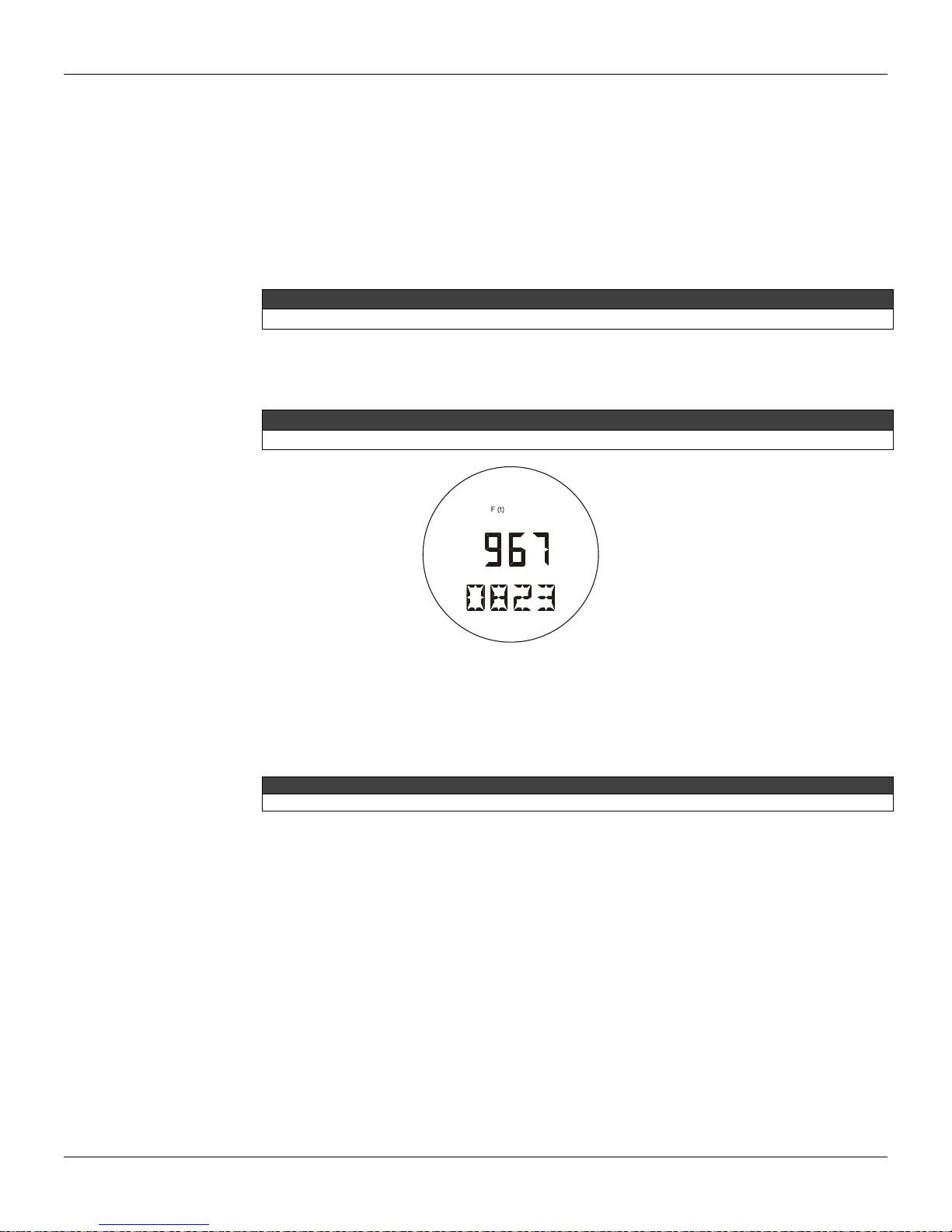
Configuration
+ SIGNIFICATIVE
WARNING
The total value is not lost with power drop.
The method uses such totalization and, through three parameters (MAXIMUM FLOWRATE, TOTAL
INCREMENT and TOTAL UNIT), converts it to the user-defined totalizing unit:
MAXIMUM FLOW RATE - this is the maximum flow rate expressed in volume or mass units per
second, corresponding to the measurement (PV%=100%). For example: m3/s, bbl/s, kg/s, lb/s;
TOTALIZATION INCREMENT - this is used to convert the flow rate base unit into a multiple unit
of mass or volume. For example, a flow rate totalized in gallons/s may be converted to a volume
in m3; a mass flow rate of g/s may be converted to kilos, etc.
TOTALIZATION UNIT - this is the engineering unit. It shall be associated to the totalized value.
It may be a standard unit or a special unit with up to five characters.
WARNING
To configure any these parameters, the totalizer should be disable.
The largest totalized value is 99.999.999 totalizing units. When the totalization is displayed, the most
significant part is shown on the numeric field, and the less significant part is shown on the
alphanumeric field. Figure 4.5 shows a typical display indication.
NOTE
F(t) indication is activated every time the totalized value is shown on the digital display.
- SIGNIFICATIVE
Figure 4.5 – Typical Monitoring Mode Display Showing the Total, in this case 19.6708.23
The following services are associated with the Totalizer:
INITIALIZATION - Totalization is reinitialized from value "0";
ENABLING/DISABLING - this allows the totalization function to be enabled or disabled.
Example: A differential pressure of 0 - 20 inH
In CONF set Lower = 0 inH
O and Upper = 20 inH2O.
2
O represents a flow of 0 - 6800 dm³/minute.
2
In order to adjust the MAX._FLOW, the maximum flow must be converted to cubic decimeters per
second: 6800 / 60 = 113.3 dm
3
/s.
The selection of the totalization unit (U_TOTAL) is made in function of the maximum flow and the
minimum time allowable for the counter overrun, i.e., the time required for the totalization to reach
99.999.999.
In the example, if U_TOTAL = 1, the totalization increment is 1 dm
3
. The time required for the
overrun with maximum flow is 245 hours, 10 minutes and 12.5 seconds.
On the other hand, in case a TOTALIZATION INCREMENT equal to 10 is used, the totalized unit
will be deciliter (dal) and the totalizer will receive one increment at every 10 dm
maximum flow rate (113.3 dm
3
/s), the totalizer will reach its maximum value and return to zero in10
3
. Considering the
days, 5 hours, 10 minutes e 12.5 seconds.
4.11

LD400 HART® – Operation and Maintenance Instruction Manual
All these parameters accept zero as input. Such value simply nullifies the corresponding PID
control actions.
PID Controller Configura t ion
The LD400 HART® may be factory -configured to work as Transmitter only or as Transmitter /
Controller. In case the LD400 HART
change its operation mode at any time simply by configuring an internal status variable.
As a PID Controller, the LD400 HART® may run a PID type control algorithm, where its 4 to 20 mA
will represent the status of the Manipulated variable (MV). In such a mode, output is 4 mA when the
MV = 0% and 20 mA when MV = 100%.
The PID implementation algorithm is:
MV = Kp (e + 1/Tr ∫ e dt + Td dPV/dt )
Where:
e(t) = PV-SP (direct) SP-PV (reverse)
SP = Setpoint
PV = Process Variable (Pressure, Level, Flow, etc.)
Kp = Proportional Gain
Tr = Integration Time
Td = Derivative Time
MV = Manipulated Variable (output)
The three configuration groups below are pertinent to the PID controller:
SAFETY LIMITS - this group enables the configuration of: Safety Output, Output Rate and Output
Lower and Upper Limits.
The Safety Output defines the value of the output in the case of equipment failure.
Output Rate is the maximum variation Rate allowed for the output, expressed in %/s.
The Lower and Upper Limits define the output range.
TUNING - this group enables the PID tuning to be performed. The following parameters may be
adjusted: Kp, Tr and Td.
Parameter Kp is the proportional gain (not the proportional band) that controls the PID proportional
action. It may be adjusted from 0 to 100.
Parameter Tr is the integral time that controls the PID integral action. It may be adjusted from 0 to
999 minutes per repetition.
Parameter Td is the derivative time controlling the PID derivative action. It may be adjusted from 0
to 999 seconds.
®
is configured as a Transmitter / Controller, the end user may
NOTE
OPERATION MODES - this group enables the configuration of: Control Action, Setpoint Tracking
and Power On.
The Control Action Mode enables the selection of the desired output action: direct or reverse. In
direct action, a PV increase causes an output increase; in reverse action, a PV increase causes an
output decrease.
When the Setpoint Tracking mode is enabled, it is possible for the Setpoint to follow the PV while in
Manual Control. Thus, when control passes to Auto, the Setpoint value will be that of the last PV
prior to the switching.
When the PID is enabled, the Power On mode allows the adjustment of the mode in which the PID
controls shall return after a power failure: Manual mode, Automatic mode or the last mode prior to
the power failure.
TABLE – If the table option is selected, the MV output will follow a curve according to the values
typed in the LD400 HART
®
characterization table. The points can freely be configured as
percentage values. For a better linearization, it is recommendable that the points are the closest
possible, in the less linear regions of the curve. The LD400 HART
enable and disable the characterization table of the MV output of the PID.
4.12
®
has an internal variable to

The output current will be increased to 4 mA as the LD400 HART® address , in the Transmitter
configured in the Controller mode).
PARÂMETER
DESCRIPTION
CURRENT
Current in mille amperes.
OUT% = (MV% (*))
Output in percentage.
PV
Process Variable in engineering units.
PV%
Process Variable in percentage.
TEMP
Ambient temperature.
TOTAL
Total accumulated by the totalizer.
SP% (*)
Setpoint in percentage.
SP (*)
Setpoint in engineering units.
NONE
Used to cancel the second indication.
Items marked with an asterisk can only be selected in the PID mode. Total can only be selected if
enabled.
Equipment Configura t ion
The LD400 HART® enables the configuration not only of its operational services, but of the
instrument itself. This group includes services related to: Input Filter, Burnout, Addressing, Display
Indication and Passwords.
INPUT FILTER - The Input Filter, also referenced to as damping, is a first class digital filter
implemented by the firmware. User configurable from any value higher than zero seconds in
addition to intrinsic sensor response time (0.2 s) (via digital communication). The transmitter
mechanical damping is 0.2 seconds.
BURN OUT - The output current may be programmed to go to the maximum limit of 21 mA (Full
Scale) or to the minimum limit of 3.6 mA in case of transmitter failure. Configuring the
BURNOUT parameter for Upper or Lower may do this. The BURNOUT configuration is only
valid in the transmitter mode. When a failure occurs in the PID mode, the output is driven to a
safety Output value, between 3.8 and 20.5 mA.
ADDRESSING - The L D400 HART® includes a variable to define the equipment address in a
HART network. Addresses may go from value "0" to "15"; addresses from "1" to "15" are
specific addresses for multidrop connections. This means that, in a multidrop configuration, the
LD400 HART
mode, is altered to another value than "0" (this does not happen when the LD400 HART® is
®
will display the message MDROP for addresses "1" to "15".
NOTE
Configuration
The LD400 HART® is factory-configured with address "0".
DISPLAY INDICATION - the LD4 00 HART® digital display is comprised of three distinct fields:
an information field with icons indicating the active configuration status, a 4 ½ digit numeric field
for value indication and a 5 digit alphanumeric field for units and status information.
The LD400 HART® may work with up to two display configurations to be alternately displayed at 2
second intervals. Parameters that may be selected for visualization are those listed on Table 4.4,
below.
ER% (*) Error in percentage (PV% - SP %).
Table 4.4– Variables for Display Indication
NOTE
PASSWORDS - this service enables the user to modify the operation passwords used in the
LD400 HART®. Each password defines the access for a priority level (1 to 3); such configuration
is stored in the LD400 HART
®
EEPROM. Password Level 3 is hierarchically superior to
password level 2, which is superior to level 1.
4.13

LD400 HART® – Operation and Maintenance Instruction Manual
Nº
OPTION
DESCRIPTION
1
LD400
Differential, Flow, and Level Transmitter
2
D2
Differential, Range: -5 0 a 50 kPa.
3
1
Stainless Steel 316L Diaphragm and Fill Fluid with Silicone Oil
4
0
Class of Standard performance
5
H
HART® Transmitter 4-20 mA
6
1
SIS: Safety Integrity Systems
7
I
Flanges, Adapters, and 316 Stainless steal Drain/Vent valves
8
B
Buna-N O-Rings
9
U
Drain in up position
10
0
Process Connection: 1/4 - 18 NPT (Without Adapter)
11
0
Without Special Cleaning
12
P
Flanges, nuts, and bolts Material: Plated Carbon Steel
13
0
Flange Threaded for accessories fixing (adapters, manifolds, etc): 7/16” UNF.
14
1
With Digital Indicator
15
0
Electrical connection 1/2 NPT
16
I
316 Blank conduit Plug
316 Stainless Steel Blank conduit Plug. Mounting Blacket for 2” Pipe or surface
mounting: Blacket and Accessories in Carbon Steel
18
A
Electronic Housing: Aluminum
19
0
Painting: N6, 5 Munsell Gray Polyester
20
N
Without identification
21
0
None
22
0
TAG plate: with tag, when specified
23
BU
Burn-out: full Scale
24
Y2
LCD1 Indication: Pressure (Engineering Units)
25
Y5
LCD2 Indication: Temperature (Engineering Units)
26
P2
Available and enable PID
27
F1
Transfer Function for flow measure: Square Root
The transmitter number must be changed whenever there is the main plate change to avoid
communication problems.
1 2 3 4 5 6 7 8 9 10
11 12
13
14 15
16
17 18
19
20
21
22 23
24
25
26
27
LD400
-
D2 1 0 - H 1 - I B U 0 0 - P 0 1 - 0 I 1 - A 0 N 0 0 /
BU
Y2
Y5
P2
F1
Equipment Maintenance
Here are grouped maintenance services related with the collection of information required for
equipment maintenance. The following services are available: Order Code, Serial Number,
Operation Counter and Backup/Restore.
ORDER CODE - The Order Code is the one used for purchasing the equipment, in accordance
with the User specification. There are 22 characters available in the LD400 HART
this code and the last one is a bar that must be placed at the end of the main code; the
sequential characters are optional *. The optional items may select or not, according to user
needs. Example:
®
to define
17 1
SERIAL NUMBER - Three serial numbers are stored:
Circuit Number - This number is unique to each main circuit board and cannot be changed.
Table 4.5– Differential Pressure Transmitter Ordering Code
Sensor Number - The serial number of the sensor connected to the LD400 HART® and cannot be
changed. This number is read from the sensor every time a new sensor is inserted in the main
board.
Transmitter Number - The number that is written at the identification plate in each transmitter.
NOTE
OP_COUNT - Every time a change is made, there is an increment in the respective change
counter for each monitored function, according to the table 4.6. The counter is cyclic, from 0 to
255. The monitored items are:
4.14

Configuration
VARIABLE
DESCRIPTION
Lower Value/Upper Value
When any type of calibration is done.
When any change in the transference function is done, e.g., linear,
square root, const, table.
Trim_20mA
When the current trim is done at 20mA.
Trim_Zero/Lower
When pressure trim is done at Zero or Lower Pressure.
Trim Upper Pressure
When the trim is done at Upper Pressure.
Temperature Trim
When the temperature is done.
When any change is made in the operation mode, i.e., from PID to TRM
or vice versa.
When any change is made in the totalization, configuration or in the
reset.
Table
When the contents on the transference function table is altered.
Password
When any change is made in the password
Function
Trim_4mA When the current trim is done at 4mA.
Characterization
TRM/PID
Totalization
Multidrop
When any change is made in any point of the pressure characterization
table in trim mode.
When any change is made in the communication mode, for example,
multidrop or single transmitter.
Table 4.6 – Functions Monitored by the Operation Counter
BACKUP - W hen the main board is changed, after assembling and powering it, the data saved
in the sensor memory are automatically copied to the main board memory, allowing its
operation.
RESTORE - This option allows copying the data saved in the sensor memory to the main board
memory. It also allows restoring to the main board the data stored in the sensor.
4.15

LD400 HART® – Operation and Maintenance Instruction Manual
4.16

Section 5
The Magnetic Tool
PROGRAMMING USING LOCAL
ADJUSTMENT
With the Magnetic Tool it is possible to configure locally the LD400 HART
additional configurators in many basic applications.
There are two ways to adjust the LD400 HART
Table 5.1):
®
locally according to the jumper configuration (see
Simple Local Adjustment
Complete Local Adjustment
For the configuration with the magnetic tool to be possible:
The display must be connected;
The writing protection jumper must be disabled;
The local adjustment jumper must be enabled on simple mode or complete mode.
See on Figure 5.1 the jumper positions for Local Adjustment and Writing Protection on the main board.
If the option chosen be for the Complete Adjustment, with a disabled writing protection and w ithout the
display connected, the transmitter will redirect automatically the local adjustment for Simple mode. This
happens because the Complete Local Adjustment needs an interaction with the display, and Simple
Local Adjustment doesn’t.
Local Adjustment In the transmitter mode, the simple local adjustment is used for Zero and Span
Calibration.
On the other hand, the Complete Local Adjustment makes possible to use the transmitter for sever al
operations, both for control and for configuration.
®
and eliminate the need for
To configure the Local Adjustment, set the main board jumpers as shown on Table 5.1.
Figure 5.1 – Main Board
5.1

LD400 HART® – Operation and Maintenance Instruction Manual
Local Adjustment
Writing Protection
Simple Mode
Enable
Disable
Complete
Mode Enable
Enable Writing
Disable Writing
Notes:
1 - If the writing protection (WP ON) is selected, the writing in EEPROM will be protected.
2 – The standard configuration for the tools is the local adjustment selected for simple, and the writing pr otection is disabled.
5.2
Table 5.1– Local Adjustment Selection

ADJUSTMENT
ADJUSTMENT
TRANSMITTER
MODE
CONTROLLER
MODE
TRANSMITTER
MODE
CONTROLLER
MODE
Moves among options
in OPERATION and
Moves among all the
options TOTAL
Activates the selected
Functions
Activates the selected
Functions
Local Adjustment
Programming Using Local Adjustment
Under the identification plate, the transmitter has two orifices where the magnetic tool is inserted t o set
the Local Adjustment. See Figure 5.2.
Figure 5.2 – Zero and Span Local Adjustment
The holes are marked with Z ( Zero) and S (Span) and from now on will be simply described as (Z) and
(S), respectively. Table 5.2 shows the action performed by the magnetic tool while inserted in (Z) and
(S) in accordance with the selected adjustment type.
Browsing the functions and their branches works as follows:
Inserting the handle of the magnetic tool in (Z), the transmitter passes from the normal
measurement state to the transmitter configuration state. The transmitter software
automatically starts to display the available functions in a cyclic routine. The grou p of funct ions
displayed depends on the mode selected for the LD400 HART
Controller.
In order to reach the desired option, browse the options, wait until they are displayed and move
the magnetic tool from (Z) to (S). Refer to Figure 5.3 – Local Adjustment Programming Tr ee, in
order to know the position of the desired option. By placing the magnetic tool once agai n in (Z),
it is possible to browse other options within this new branch.
The procedure to reach the desired option is similar to the one described on the previous i tem,
for the whole hierarchical level of the programming tree.
SIMPLE LOCAL
COMPLETE LOCAL
®
, either Transmitter or
ACTION
Z
S
Simple Local Adjustment
The performance form of the Simple Local Adjustment is how it proceeds:
Zero Calibration: when inserting the magnetic tool in the (Z) hole, the measured pressure w ill
be equivalent to the 4 mA current pressure;
Span Calibration: when inserting the magnetic tool in the (S) hole, the measured pressure will
be equivalent to the 20 mA current pressure.
Selects the Lower Range Value
Selects the Upper Range Value
Table 5.2- Local Adjustment Description
Moves among all the
options
5.3

LD400 HART® – Operation and Maintenance Instruction Manual
NOTE
the Technical Specification (Section 3).
For adequate calibration, notice the minimum span for each measu ring rang e and types as defined on
Zero calibration with reference shall be done as follows:
Apply the Lower Value pressure;
Wait for the pressure to stabilize;
Insert the magnetic tool in the ZERO adjustment holes. (See Figure 5.2);
Wait 2 seconds and the transmitter should be reading 4 mA;
Remove the tool.
Zero calibration with reference does not affect the span. In order to change the span, the following
procedure shall be observed:
Apply the Upper Value pressure;
Wait for the pressure to stabilize;
Insert the magnetic tool in the SPAN adjustment hole (S);
Wait 2 seconds. The transmitter should be reading 20 mA.;
Remove the tool.
Zero adjustment causes zero a new upper value (URV) is calculated in accordance with the effective
span. In case the resulting URV is higher than the Upper Limit Value (URL), the URV w ill be limited to
the URL value, and the span will be automatically affected.
Complete Local Adjustment
The following functions are available for local adjustment: Simulation, Range, Trim, Configuration,
Operation and Quit.
5.4

Programming Using Local Adjustment
RANGESIMUL TRIM CONF OPER
QUIT
Z
Z
S
SSSSSS
4 mA
8 mA
12 mA
16 mA
20 mA
ESC SIMUL
Zero Reference
Span Reference
LRV
Lower
Lower
Save
Esc
URV
URV
URV
Save
Esc
Unit...
ftH2O
mmH2O
inHg
inH2O
mmHg
psi
Bar
mBar
gf/cm2
kgf/cm2
Pa
kPa
mH2O
atm
MPa
Esc
ESC RANGE
PSWRD
Esc
Trim
Lower
Upper
Lower
Lower
Save
Esc
ESC TRIM
DAMP
DAMP
Save
Esc
Damp
Function
Linear
Sqrt
Esc
LCD
LCD1
ImA
AO%
Press
PV%
PV
Esc
LCD2
ImA
AO%
Press
PV%
PV
Esc
AO%
LCD3
ImA
AO%
Press
PV%
PV
Esc
Address
Addr
Addr
Save
Esc
ESC CONF
Reset T otal
PASSWORD
Esc
A/M
SP
SP
SP
Save
Esc
MV
MV
MV
Save
Esc
ESC OPER
Quit
DISPLAY
ZZZZZ
LRV
LRV
Save
Esc
NONE
NONE
Esc
Figure 5.3 – Local Adjustment Programming Tree – Main Menu
S
Z
ACTION
MOVE
AROUND
5.5

LD400 HART® – Operation and Maintenance Instruction Manual
WARNING
before configuration, to switch the loop to manual. And do not forget to return to auto after
8 mA
4 mA
12mA
16 mA 20 mA
ESC
Z
S
SIMUL
SIMUL
RANGE
ZZZZZ
S
Z
SIMUL
4 mA
Simulation [SIMUL]
When programming using local adjustment, the transmitter will not prompt "Control lo op should be in
manual!" as it does when using the HART
®
configurator for programming. Therefore it is a good idea,
configuration is completed.
The main branch starts at the “SIMUL” option.
SIMULATION (SIMUL) – Simulation loop test current. Options: 4 mA, 8 mA, 12 mA, 16 mA or 20 mA.
RANGE (RANGE) – It is the option allows operation range zero, span, lower and upper values
calibration.
TRIM (TRIM) – It is the option used to calibrate the "with reference" characterization and the digital
reading.
CONFIGURATION (CONF) – Is the option where the output and display related parameters are
configured: damping, function, display and address.
OPERATION (OPER) – Is the option where the operation related parameters of the controller are
configured: Reset, Auto/Manual, Setpoint and Manual output.
QUIT - Is the option used to go back to normal monitoring mode.
This operation simulates the output current for the Loop test. Optional values to be simulated are
4 mA, 8 mA, 12 mA, 16 mA or 20 mA.
Figure 5.4 – Simulation Calibration Branch of Complete Local Adjustment Tree
SIMULATION BRANCH (SIMUL)
Z: Moves enter main branch options of complete local adjustment tree.
S: Enter in the Simulation Adjustment Branch [SIMUL].
Z: Moves enter available simulation value options.
S: Enter with 4 mA value for simulation.
5.6

Programming Using Local Adjustment
8 mA
12 mA
16 mA
SIMUL
ESC
NOTE
After entering a simulation current value, the LD400 HART® automatically quits the simulation mode in
around 2 minutes. Other configuration branches are also abandoned in fairly less time, around 8 seco nds.
Z: Moves enter available simulation value options.
S: Enter with 8 mA value for simulation.
Z: Moves enter available simulation value options.
S: Enter with 12 mA value for simulation.
Z: Moves enter the available simulation value options.
S: Enter with 16 mA value for simulation.
Range [RANGE]
Z: Moves enter available simulation value options.
20 mA
S: Enter with 20 mA value for simulation.
Z: Moves enter main branch options of complete local adjustment tree.
S: Escapes to the Simulation Branch [SIMUL].
This option makes zero and span calibration, also called calibration with reference, or define lower and
upper operation values, while performing calibration without reference. The unit associated to pressure
measuring may also be modified in this branch.
5.7

LD400 HART® – Operation and Maintenance Instruction Manual
SPANZERO LRV URV UNIT
RANGE
LRV
LRV
Save
Esc
URV
URV
Save
Esc
ftH2O
mmH2O
inHg
inH2O
mmHg
psi
Bar
mBar
gf/cm2
kgf/cm2
Pa
kPa
mH2O
atm
MPa
Esc
ESC
Z
S
RANGE
TRIM
ZZZZZ
S
Z
RANGE
ZERO
LRV
SPAN
Figure 5.5 – Range Calibration Branch of Complete Local Adjustment Tree
RANGE BRANCH [RANGE]
Z: Moves enter main branch options of complete local adjustment tree.
S: Enters the RANGE branch [RANGE].
Z: Moves enter options Range Adjustment Branch [RANGE].
S: Increases zero value.
Z: Moves enter options Range Adjustment Branch [RANGE].
S: Increases span value.
Z: Moves enter options Range Adjustment Branch [RANGE].
S: Enters the Lower Range Value branch.
5.8

Programming Using Local Adjustment
LRV
LRV
SAVE
INC
ESC
URV
URV
URV
SAVE
Z: Moves enter LRV DECREASE function.
S: Increases the Lower Value until the magnetic tool is removed or the maximum
Lower Value is reached.
Z: Moves enter options Lower Range Value Adjustment Branch. [LRV].
S: Decreases the Lower Value until the magnetic tool is removed or the minimum
Lower Value is reached.
Z: Moves enter options Lower Range Value Adjustment Branch. [LRV].
S: Save the adjust Lower Range Value.
Z: Moves enter options Lower Range Value Adjustment Branch. [LRV].
S: Escapes to the Lower Range Value menu.
Z: Moves enter options Range Branch.
S: Enter in the Upper Range Value adjustment branch.
Z: Moves enter options Upper Range Value Adjustment Branch. [URV].
S: Increases Upper Range Value.
Z: Moves enter options Upper Range Value Adjustment Branch. [URV].
S: Decreases Upper Range Value.
Z: Moves enter options Upper Range Value Adjustment Branch. [URV].
S: Save the Upper Range Value adjustment.
5.9

LD400 HART® – Operation and Maintenance Instruction Manual
INC
ESC
UNIT
inH2O
inHg
ftH2O
mmH2O
mmHg
psi
Z: Moves enter options Upper Range Value Adjustment Branch. [URV].
S: Escapes to the Upper Range Value menu.
Z: Moves enter options Range Adjustment Branch
S: Enter in the Engineering Units adjustment branch [UNIT].
Z: Moves enter the options Engineering Units Branch [UNIT].
S: Select inH
O and comes back to the options tree main branch of complete local
2
adjustment.
Z: Moves enter the options Engineering Units Branch [UNIT].
S: Select inHg and comes back to the options tree main branch of complete local
adjustment.
Z: Moves enter the options Engineering Units Branch [UNIT].
S: Select ftH
O and comes back to the options tree main branch of complete local
2
adjustment.
Z: Moves enter the options Engineering Units Branch [UNIT].
S: Select mmH
O and comes back to the options tree main branch of complete
2
local adjustment.
Z: Moves enter the options Engineering Units Branch [UNIT].
S: Select mmHg and comes back to the options tree main branch of complete local
adjustment.
Z: Moves enter the options Engineering Units Branch [UNIT].
S: Select psi and comes back to the options tree main branch of complete local
adjustment.
5.10

Programming Using Local Adjustment
bar
mbar
gf/cm2
Kgf/cm2
Pa
kPa
mH2O
atm
Z: Moves enter the options Engineering Units Branch [UNIT].
S: Select bar and comes back to the options tree main branch of complete local
adjustment.
Z: Moves enter the options Engineering Units Branch [UNIT].
S: Select mbar and comes back to the options tree main branch of complete local
adjustment.
Z: Moves enter the options Engineering Units Branch [UNIT].
S: Select gf/cm
2
and comes back to the options tree main branch of complete local
adjustment.
Z: Moves enter the options Engineering Units Branch [UNIT].
S: Select kgf/cm
2
and comes back to the options tree main branch of complete
local adjustment.
Z: Moves enter the options Engineering Units Branch [UNIT].
S: Select Pa and comes back to the options tree main branch of complete local
adjustment.
Z: Moves enter the options Engineering Units Branch [UNIT].
S: Select kPa and comes back to the options tree main branch of complete local
adjustment.
Z: Moves enter the options Engineering Units Branch [UNIT].
S: Select mH
O and comes back to the options tree main branch of complete local
2
adjustment.
Z: Moves enter options Engineering Units Branch [UNIT].
S: Select atm and comes back to the options tree main branch of complete local
adjustment.
5.11

LD400 HART® – Operation and Maintenance Instruction Manual
MPa
UNIT
ESC
RANGE
ESC
Z: Moves enter options Engineering Units Branch [UNIT].
S: Select MPa and comes back to the options tree main branch of complete local
adjustment.
Z: Moves enter options Engineering Units Branch [UNIT].
S: Escapes to the Engineering Unit adjustment branch and comes back to the
options Range Adjustment Branch [RANGE].
Z: Moves enter options Range Adjustment Branch [RANGE].
S: Escapes to the Range adjustment branch and comes back to the tree main branch of complete local
adjustment.
Pressure Trim [TRIM]
This field of the tree is used to adjust the digital reading according to the applied pressure. The
pressure TRIM differs from RANGING WITH REFERENCE, since the TRIM is used to correct the
measure and RANGING WITH REFERENCE reach only the applied pr essure with the output signal of
4-20 mA.
Figure 5.6 shows the options available to run the pressure TRIM.
TRIM
Z
Z
PSWRD
S
Zero Trim
Lower
Lower
Lower
Save
Esc Inc
Upper
Upper
Upper
Save
Esc INC
S
ESC
TRIM
Figure 5.6 – Pressure Trim Tree
S
5.12

Programming Using Local Adjustment
PSWRD
0
PSWRD
ESC
Z TRIM
Lower
Lower
Lower
SAVE
INC
ESC
PRESSURE TRIM BRANCH [TRIM]
Z: Moves enter 0 PSWRD and ESC PSWRD.
S: T his function is pr otected by a "password," when prompted 0 P SWD, enter the password. The passw ord
code is entered by inserting and removing the magnetic tool twice in (S). The password value is changed
from 0 to 1. After entering the "password," you can move around the options Trim Branch using (Z). To
select the desired option, activate (S).
Z: Moves enter 0 PSWRD and ESC PSWRD.
S: Escapes to the PSWRD branch and comes back to the Pressure Trim Tree [TRIM].
Z: Moves the TRIM Branch options.
S: Zero Calibration: Trims the transmitter internal reference to read 0 at the
applied pressure.
Z: Moves enter TRIM Branch options.
S: Enters in the configuration’s branch Lower Pressure Trim.
Z: Moves enter Lower Pressure TRIM Branch
(LOWER).
S: Adjusts the transmitter internal reference, increasing
the displayed value that will be interpreted as the Low er
Pressure value corresponding to the applied pressure.
Z: Moves enter Lower Pressure TRIM Branch
(LOWER).
S: Adjusts the transmitter internal reference, decreasing
the displayed value that will be interpreted as the Low er
Pressure value corresponding to the applied pressure.
Z: Moves enter Lower Pressure TRIM Branch
(LOWER).
S: Save the Lower Pressure Trim adjustment and
comes back to the tree main branch of complete local
adjustment.
Z: Moves enter Lower Pressure TRIM Branch
(LOWER).
S: Escapes the Trim adjustment and comes back to
the tree main branch of complete local adjustment.
5.13

LD400 HART® – Operation and Maintenance Instruction Manual
Upper
Upper
Upper
SAVE
back to the tree main branch of complete local
INC
ESC
back to the tree main branch of complete local
TRIM
ESC
Z: Moves enter TRIM Branch.
S: Enters in the configuration’s branch Upper Pressure Trim.
Z: Moves enter Upper Pressure TRIM Branch
(UPPER).
S: Sets the transmitter internal reference increasing to
the value on the display, which is the reading of the
applied pressure.
Z: Moves enter Upper Pressure TRIM Branch
(UPPER).
S: Sets the transmitter internal reference decreasing to
the value on de display, which is the reading of the
applied pressure.
Z: Moves enter Upper Pressure TRIM Branch
(UPPER).
S: Save the Upper Range Value adjustment and comes
adjustment.
Z: Moves enter Upper Pressure TRIM Branch
(UPPER).
S: Escapes the Pressure Trim Adjustment and comes
Configuration [CONF]
Configuration functions affect directly the 4-20 mA output current and the display indication. The
configuration options implemented in this branch are the following:
Digital filter damping time configuration of the readout signal input;
Selection of the transference function to be applied to the measured variable;
Selection of the variable to be shown on Display 1, Display 2 and Display 3;
Proportional Gain Adjustment (Kp).
Figure 5.7 shows branch CONF with the available options.
5.14
adjustment.
Z: Moves enter TRIM Branch options.
S: Escapes the Pressure Trim Adjustment and comes back to the tree main
branch of complete local adjustment.

Programming Using Local Adjustment
CONF
DAMP
Z
LCD
S
LCD1
ImA
AO%
Press
PV%
PV
ESC
LCD2
ImA
AO%
Press
PV%
PV
ESC
LCD3
ImA
AO%
Press
PV%
PV
ESC
ESC LCD
OPER
Address
S
Addr
Addr
Save
Esc INC
Z
ESC
CONF
S
S
DAMP
DAMP
Save
Esc DAMP
CONF
S
Z
FunctDAMP
S
Linear
Sqrt
Esc Funct
Z Z Z
Figure 5.7 – Local Adjustment Configuration Tree
CONFIGURATION BRANCH [CONF]
Z: Moves enter main branch options of complete local adjustment tree.
S: Enters the CONFIGURATION branch.
Z: Moves enter Configuration Branch options.
S: Enters the Damping Time Branch.
5.15

LD400 HART® – Operation and Maintenance Instruction Manual
DAMP
DAMP
SAVE
INC
ESC
FUNCT
Linear
Sqrt
FUNCT
ESC
Z: Moves enter Damping Time Branch options.
S: Increases the damping time constant until the magnetic tool is removed or
128 seconds are reached.
Z: Moves enter Damping Time Branch options.
S: Decreases the damping time constant until the magnetic tool is removed or 0
seconds is reached.
Z: Moves enter Damping Time Branch options.
S: Save the adjustment and comes back to the tree main branch of complete
local adjustment.
Z: Moves enter Damping Time Branch options.
S: Escapes the Adjustment branch and comes back to the options main branch
of configuration tree [CONF].
Z: Moves enter Configuration Branch options.
S: Enters the Function Transfer branch.
Z: Moves enter Function Transfer options.
S: Selected of input function and comes back the Configuration Branch [CONF].
Z: Moves the Function Transfer options.
S: Selected of Square Root function and comes back the Configuration Branch
[CONF].
5.16
Z: Moves enter Function Transfer options.
S: Escapes the Function Transfer Adjustment branch and comes back to the
options main branch of configuration tree [CONF].

LCD
LCD1
ImA
AO%
Press
PV%
PV
LCD
ESC
Programming Using Local Adjustment
Z: Moves enter Configuration Branch options [CONF].
S: Enter the Display Branch [LCD].
Z: Moves enter options: LCD1, LCD2, LCD3 e ESC LCD.
S: Enter the Display 1 Branch [LCD1].
Z: Moves enter variable to be indicated as primary
display.
S: Select current in mA [ImA].
Z: Moves enter variable to be indicated on the Display 1.
S: Select the analog output in percentage [AO].
Z: Moves enter variable to be indicated on the Display 1.
S: Select the Pressure (Engineering Unit) [Press].
Z: Moves enter variable to be indicated on the Display 1.
S: Select Process Variable in Percentage [PV%].
Z: Moves enter variable to be indicated on the Display 1.
S: Select Process Variable [PV].
Z: Moves enter variable to be indicated on the Display 1.
S: Escapes the choose Display 1 variable branch.
5.17

LD400 HART® – Operation and Maintenance Instruction Manual
ImA
AO%
Press
PV%
PV
NONE
LCD
ESC
Z: Moves enter options: LCD1, LCD2, LCD3 e ESC LCD.
LCD2
S: Enter the Display 2 Branch [LCD2].
Z: Moves enter variable to be indicated in the Display 2.
S: Select the current in mA [ImA].
Z: Moves enter variable to be indicated on the Display 2.
S: Select the analog output in percentage [AO].
Z: Moves enter variable to be indicated on the Display 2.
S: Select the Pressure (Engineering Unit) [Press].
Z: Moves enter variable to be indicated on the Display 2.
S: Select the Process Variable in Percentage [PV%].
Z: Moves enter variable to be indicated on the Display 2.
S: Select the Process Variable [PV].
Z: Moves enter variable to be indicated on the Display 2.
S: Selects the option for not showing the readout on
Display 2.
5.18
Z: Moves enter variable to be indicated on the Display 2.
S: Escapes the choose Display 2 variable branch.

LCD3
ImA
AO%
Press
PV%
PV
NONE
LCD
ESC
Programming Using Local Adjustment
Z: Moves enter options: LCD1, LCD2, LCD3 e ESC LCD.
S: Enter the Display 3 Branch [LCD3].
Z: Moves enter variable to be indicated in the Display 3.
S: Select the output in mA [ImA].
Z: Moves enter variable to be indicated in the Display 3.
S: Select analog output in percentage [AO].
Z: Moves enter variable to be indicated in the Display 3.
S: Select the Pressure (Engineering Unit) [Press].
Z: Moves enter variable to be indicated in the Display 3.
S: Select the Process Variable in Percentage [PV%].
Z: Moves enter variable to be indicated in the Display 3.
S: Select Process Variable [PV].
Z: Moves enter variable to be indicated in the Display 3.
S: Selects the option for not showing the indication on
Display 3.
Z: Moves enter variable to be indicated in the Display 3.
S: Escapes the choose Display 3 variable branch.
5.19

LD400 HART® – Operation and Maintenance Instruction Manual
LCD
ESC
Address
Addr
Addr
SAVE
INC
ESC
CONF
ESC
Z: Moves enter options: LCD1, LCD2, LCD3 e ESC LCD.
S: Escapes LCD branch and comes back Configuration branch [CONF].
Z: Moves enter Configuration Branch options [CONF].
S: Enter in Address Branch.
Z: Moves enter available options to address adjustment.
S: Increases the value on the address shown on the display.
Z: Moves enter available options to address adjustment.
S: Decreases the value on the address shown on the display.
Z: Moves enter available options to address adjustment.
S: Save the address adjusted.
Z: Moves enter available options to address adjustment.
S: Escapes equipment address adjustment branch.
Z: Moves enter Configuration Branch options [CONF].
S: Escapes the Configuration Adjustment Branch and comes back to main branch options of complete
local adjustment tree.
5.20

OPER
R TOT
PWRD
Operation [OPER]
Programming Using Local Adjustment
This adjustment option is applicable to the LD400 HART
®
configured in the Controller mode. It allow s
the control state to be changed from Automatic to Manual and vice versa, and also to adjust the
Setpoint and Manipulated Variable values. Figur e 5.8 shows branch OPER w ith the available options.
If the equipment is configured on Transmitter mode, only the total Reset will be available.
Equipment Configured on Transmitter Mode
S
S
OPER
S
R TOT
S
PSWRD
ESC
Z
Z
QUIT
Z
ESC
OPER
Figure 5.8 - Local Adjustment Operating Tree
OPERATION BRANCH (OPER) – TRANSMITTER MODE
Z: Moves enter main branch options of complete local adjustment tree.
S: Enters the OPERATION branch [OPER].
Z: Moves enter Operation Branch.
S: Ask password [PSWRD].
Z: Moves enter 0 PSWRD and ESC PSWRD.
S: This function is protected by a "password," when prompted 0 PSWD, enter the
password. The password code is entered by inserting and removing the magnetic
tool twice in (S). The password value is changed from 0 to 1. After entering the
"password," you can move around the options Trim Branch using (Z). To select the
desired option, activate (S).
5.21

LD400 HART® – Operation and Maintenance Instruction Manual
PSWRD
ESC
OPER
ESC
OPER
R TOT
Z: Moves enter 0 PSWRD and ESC PSWRD.
S: Escapes the PSWRD Branch and comes back the Operation Tree [OPER].
Z: Moves enter Operation Branch options.
S: Escapes Operation Tree Branch [OPER].
Equipment Configured on Controller Mode
Z
SP MV
S S
SP
SP
Save
Esc INC
MV
MV
Save
Esc INC
Z
S
ESC
OPER
S
PSWRD
Esc
OPER QUIT
S
Z
A/MR TOT
Z Z Z
Figure 5.9 - Operation branch on Local Adjustment Tree controller mode
OPERATION BRANCH [OPER] – CONTROLLER MODE
Z: Moves enter main branch options of complete local adjustment tree.
S: Enter in the Operation Branch [OPER].
Z: Moves enter Operation Branch options [OPER].
S: Ask password [PSWRD].
5.22

Programming Using Local Adjustment
PSWRD
0
activate (S).
PSWRD
ESC
A/M
SP
SP
SP
SAVE
INC
ESC
Z: Moves enter Operation Branch options [OPER].
S: Toggles controller status, Automatic to Manual or Manual to Automatic. A and M indicate status.
Z: Moves enter Operation Branch options [OPER].
S: Enter in the Setpoint adjustment branch [SP].
Z: Moves enter 0 PSWRD and ESC PSWRD.
S: This function is protected by a "password," when prompted 0 PSWD, enter the
password. The password code is entered by inserting and remov ing the magnetic tool
twice in (S). The password value is changed from 0 to 1. Af ter entering the "password,"
you can move around the options Trim Branch using ( Z). T o select the desired option,
Z: Moves enter 0 PSWRD and ESC PSWRD.
S: Escapes PSWRD branch and comes back Operation Tree [OPER].
Z: Moves enter increase or decrease Setpoint value, save or escape.
S: Increases the Setpoint until the magnetic tool is removed or 100% is reached.
Z: Moves enter increase or decrease Setpoint value, save or escape.
S: Decreases the Setpoint until the magnetic tool is removed or 100% is reached.
Z: Moves enter increase or decrease Setpoint value, save or escape.
S: Save Adjust Setpoint Value.
Z: Moves enter increase or decrease Setpoint value, save or escape.
S: Escapes Setpoint Adjustment Branch [SP].
5.23

LD400 HART® – Operation and Maintenance Instruction Manual
MV
MV
MV
SAVE
INC
ESC
OPER
ESC
Quit
Z: Moves enter Operation Branch options [OPER].
S: Enter in the Manipulated Variable adjustment branch [MV].
Z: Moves enter increase or decrease Setpoint value, save or escape.
S: Increases the control output until the magnetic tool is removed or the upper output
limit is reached.
Z: Moves enter increase or decrease Setpoint value, save or escape.
S: Decreases the control output until the magnetic tool is removed or the lower
output limit is reached.
Z: Moves enter increase or decrease Setpoint value, save or escape.
S: Saves the Set Point and Manipulated Variable.
Quit [QUIT]
Z: Moves enter increase or decrease Setpoint value, save or escape.
S: Escapes Manipulated Variable adjustment [MV].
Z: Moves enter Operation Branch options.
S: Escapes Operation Tree Branch [OPER].
This branch of the main tree is used to leave the Local Adjustment mode, placing the Transmitter or
Controller in the monitoring mode
.
QUIT BRANCH [QUIT]
Z: Moves enter main branch options of complete local adjustment tree.
S: Escapes complete local adjustment tree and comes back to monitoring mode.
5.24

Section 6
NOTE
Equipments installed in hazardous atmospheres must be inspected in compliance with the
IEC60079-17 standard.
MAINTENANCE
General
Below, there are some important maintenance procedures that should be followed in order to have
safer plant and easy maintenance.
In general, it is recommended that end users do not try to repair printed circuit boards. Spare circuit
boards may be ordered from SMAR whenever necessary.
The sensor has been designed to operate for many years without malfunctions. Should the process
application require periodic cleaning of the transmitter, the flanges may be easily removed and
reinstalled.
Should the sensor eventually require maintenance, it may not be changed on the field. In this case,
the possibly damaged sensor should be returned to SMAR f or evaluation and, if necessary, repair.
Refer to the "Returning Materials" item at the end of this Section.
Diagnostic using Configurat ion Tool
Should any problem be noticed regarding the transmitter output, the configurator can be used to
verify what is the problem (see Table 6.1).
The configurator should be connected to the transmitter according to the wiring diagram shown on
Section 1, Figures 1.7, 1.8 and 1.9.
Error Messages
When communicating using the CONFIGURATOR the user will be informed about any problem
found by the transmitter self-diagnostics.
Table 6.1 presents a list of error messages with details for corrective actions that may be necessary.
ERROR MESSAGES POTENTIAL SOURCE OF PROBLEM
UART RECEIVER FAILURE:
• PARITY ERROR
• OVERRUN ERROR
• ERROR CHECK SUM
• FRAMING ERROR
CONFIGURATOR RECEIVES
NO ANSWER FROM
TRANSMITTER
CMD NOT IMPLEMENTED
TRANSMITTER BUSY
XMTR MALFUNCTION
COLD START
OUTPUT FIXED
OUTPUT SATURATED
• The li ne resist ance is not according to load curve;
• Excessive noise or ripple in the line;
• Low level signal ;
• Int erface damaged;
• Power supply with inadequat e vol tage.
• Transmitter line resistance is not according to load curve.
• Transmitter not powered.
• Int erface not connected or damaged
• Repeated bus address.
• Power supply with inadequat e vol tage.
• Sof tware version not compatible between configurator and
transmitter.
• Configurator is trying to carry out a LD400 HART
in a transmitter from another manufacturer.
• Transmitter carrying out an important task, e.g., local adjustment.
• Sens or disconnected;
• Sensor failure.
• Start-up or Reset due to power supplies failure.
• Output in Constant Mode;
• Transmitter in Multidrop mode.
• Press ure out of cali brat ed Span or in fail-safe state (Output current in
3.8 or 20.5 mA).
®
specific command
6.1

LD400 HART® – Operation and Maintenance Instructi on Manual
ERROR MESSAGES POTENTIAL SOURCE OF PROBLEM
SV OUT OF LIMITS
PV OUT OF LIMITS
LOWER RANGE VALUE TOO
HIGH
LOWER RANGE VALUE TOO
LOW
UPPER RANGE VALUE TOO
HIGH
UPPER RANGE VALUE TOO
LOW
UPPER & LOWER RANGE
VALUES OUT OF LIMITS
SPAN TOO SMALL
APPLIED PRESSURE TOO
HIGH
APPLIED PRESSURE TOO
LOW
EXCESS CORRECTION
PASSED PARAME TER TOO
LARGE
PASSED PARAME TER TOO
SMALL
Table 6.1 – Error Messages and Potential Source
Diagnostic via Transmit t er
Symptom: NO LINE CURRENT
Probable Source of Trouble:
Transmitter Connections
• Check wiring polarity and continuity.
• Check for shorts or ground loops.
• Check if the power supply connector is connected to main board.
Power Supply
• Check power supply output. The voltage must be between 12 and 50 Vdc at transmitter
terminals.
Electronic Circuit Failure
• Check the main board for defect by using a spare one.
Symptom: NO COMMUNICATION
Probable Source of Trouble:
Terminal Connections
• Check the terminal interface connectio n of the configurator.
• Check if the interface is connected to the wires leading to the transmitter or to the terminals
[ + ] and [ - ].
Check if the interface is compatible with HART® Protocol
• Transmitter connections.
• Check if connections are according to wiring diagram.
• Check if there is resistance in the 250 Ω
• Temperat ure out of operating l imi ts .
• Temperat ure sensor damaged.
• Press ure out of operation limi ts ;
• Sensor damaged or sensor module not connected;
• Transmitter with false configuration.
• Lower value exceeds 24% of the Upper Range Limit.
• Lower value exceeds 24% of the Lower Range Limit.
• Upper value exceeds 24% of the Upper Range Limit.
• Upper value exceeds 24% of the Lower Range Limit.
• Lower and Upper Values are out of t he sensor range limits.
• The diff erenc e, bet ween the Lower and Upper values is less than the
0.75 x (minimum span).
• The pressure appl i ed was above the 24% upper range limit.
• The pressure appl i ed was below the 24% lower range limit.
• The t rim value ent ered exceeded the fact ory-characterized value by
more than 10%.
• Param et er above operat i ng limits.
• Param et er bel ow operating l imits.
line.
6.2

Maintenance
21.0 or 3.6 mA current indicates that the transmitter is in Burnout (TRM) or safety output (PID).
Power Supply
• Check output of power supply. The voltage at the LD400 HART® terminals must be
between 12 and 50 Vdc, and ripple less than 500 mV.
Electronic Circuit Failure
• Locate the failure by alternately testing the transmitter circuit and the interface with spare
parts.
Transmitter Address
• Check if the transmitter address is compatible with the one expected by the configurator.
Symptom: CURRENT OF 21.0 mA OR 3.6 mA
Probable Source of Trouble:
Pressure Tap (Piping)
• Verify if blocking valves are fully open.
• Check for gas in liquid lines or for liquid in dry lines.
• Check the specific gravity of process fluid.
• Check process flanges for sediments.
• Check the pressure connection.
• Check if bypass valves are closed.
• Check if pressure applied is not above upper limit of the transmitter range.
Sensor to Main Circuit Connection
• Sensor connection to the Main Board.
• Check connection (male and female connectors).
Electronic Circuit Failure
• Check the sensor circuit for damage by replacing it with a spare one.
• Replace sensor.
Symptom: INCORRECT OUTPUT
Probable Source of Trouble:
Transmitter Connections
• Check power supply voltage.
• Check for intermittent short circuits, open circuits and grounding problems.
Noise Measurement Fluid
• Adjust damping
Pressure Tap
• Check for gas in liquid lines and for liquid in steam or gases lines.
• Check the integrity of the circuit by replacing it with a spare one.
Calibration
• Check calibration of the transmitter.
NOTE
A
Use the configurator to investigate the source of the problem.
6.3

LD400 HART® – Operation and Maintenance Instruction Manual
WARNING
Only use Explosion Proof/Flameproof certified Plugs, Adapters and Cable glands.
In Explosion-Proof installations the cable entries must be connected or closed using metal cable
gland and metal blanking plug, both with at least IP66 and Ex-d certification.
The standard plugs provided by Smar are certified according to CEPEL certificate. If the plug
needs to be replaced, a certified plug must be used.
The electrical connection with NPT thread must use waterproofing sealant. A non-hardening
silicone sealant is recommended.
For NEMKO ATEX certificate please to follow the installation guidelines in hazardous locations
below:
Group II Category 2G, Ex d, Group IIC, Temperature Class T6, EPL Gb
U = 28VDC
Ambient Temperature: -20 to 60ºC for T6
Environmental Protection : IP65/67 or IP65W/67W
The electrical connection available are ½ - 14NPT and M20x1,5.
Cable entries must be connected or closed using metal cable gland and metal blanking plug, both
with at least IP66 and Ex-d certification or any appropriate ATEX approved metal cable gland and
metal blanking plug.
Do not remove the transmitter covers when power is ON.
WARNING
Do not disassemble with power on.
Symptom: DISPLAY INDICATES “FAIL SENS"
Probable Source of Trouble:
Sensor Connection to the Main Board
Check the connection (flat cable, male and female connectors).
Type of Sensor Connected to the Main Board
Check if the sensor connected to the main board is the one specified for the LD400 HART®
model:
Sensor type shall be hyper - High Performance.
Electronic Circuit Failure
Check if the sensor set is damaged, replacing it for a spare one.
Information about Hazardous Locations
Disassembly Procedure
6.4
Figure 6.1 shows a transmitter exploded view and will help you to visualize the following.
Sensor
In order to have access to the sensor (29) for cleaning purposes, the transmitter should be removed
from its process connections. The transmitter should be isolated from the process by means of
manifolds or valves; then, the drain (16) must be opened to vent any remaining pressure.
After this, the transmitter may be removed from the standpipe. The flange bolts (17) may now be
loosened counterclockwise, one at a time. After removing bolts and flanges (18), the isolating
diaphragms will be easily accessible for cleaning.
Cleaning should be done carefully in order to avoid damaging the delicate isolating diaphragms. Use
of a soft cloth and a nonacid solution is recommended.
The oscillator circuit is part of the sensor. If the former is replaced, the latter should also be

Maintenance
replaced. The oscillating circuit is a part of the sensor and the replacement of one implies replacing
the other. To remove the sensor from the electronic housing, the electrical connections (in the field
terminal side) and the main board connector must be disconnected.
Loosen the hex screw (7) and carefully unscrew the electronic housing from the sensor, observing if
the flat cable is not excessively twisted.
WARNING
To avoid damage do not rotate the electronic housing more than 270º without disconnecting the
electronic circuit from the sensor and from the power supply. See Figure 6.2.
6.5

LD400 HART® – Operation and Maintenance Instructi on Manual
6.6
Figure 6.1 – Exploded View

Maintenance
WARNING
sure that these components will be handled by trained people that know the right handling
procedures. The operator and the bench must be grounded during the entire process. Also the
WARNING
right code number.
Electronic Circuit
To remove the circuit board (6), loosen the two screws (5).
The board has CMOS components, which may be damaged by electrostatic discharges. Make
circuit boards should be stored in electric-charge proof packages.
Pull the main board out of the housing and disconnect the power supply and the sensor connectors.
Reassembly Procedure
Do not assemble with power on.
Sensor
When mounting the sensor (29), make use of a new set of gaskets (20 and 21) com pat ible with th e
process fluid. The bolts, nuts, flanges and other parts should be inspected for corrosion or other
eventual damage. Damaged parts should be replaced.
The O-rings should be lightly lubricated with silicon oil before they are fitted into place. Use halogen
grease on applications having inert filling fluid. The flanges must be positioned on a flat surface.
Insert the gaskets and Backup (19) (only for high pressure) in the flange according to figure 6.1. Set
the four bolts (17) and tighten the nuts (30) initially by hand while keeping the flanges parallel
through the whole mounting and finalize with an adequate tool.
High pressure transmitters A5, A6, M5, M6 and High static pressure H2, H3, H4, H5 and the
sensors with tantalum diaphragm that use Buna-N or Viton O-ring must use a metallic backup
Ring (19) to prevent extrusion of O-ring. Do not use the backup O-Ring when using Teflon ORings or flanges that have KYNAR ins ets (PVDF).
Don’t bendin g the backup ring and inspect it for knits cuts etc. Be careful when mounting it. The
flat side, which shines more than the beveled side, shall be mounted against the O-ring (Figure
6.3).
For these models use a spring lock ring when using a Teflon ring. See the spare parts list for the
Figure 6.2– Sensor Rotation Stopper
O-RINGS AND BACKUP RINGS FOR HIGH PRESSURE
6.7

LD400 HART® – Operation and Maintenance Instructi on Manual
Figure 6.3 – Backup Ring Mounting
Procedure for tightening the flange screws
Tighten one nut till the flange seats;
Tighten the nut diagonally across with a torque of 2.5 to 3 Kgfm;
Tighten the first nut with the same torque;
Verify the flanges alignment;
Check torque on the four bolts.
Should the adapters (27) be removed, it is recommended to replace gaskets (26) and to connect the
adapters to the process flanges before coupling them to the sensor. Optimum torque is 2.5 to 3
Kgfm.
The fitting of the sensor must be done with the main board out of the electronic housing. Mount the
sensor to the housing turning it clockwise until it stops. Then turn it counterclockwise until the cover
(1) is parallel to the process flange (18). Tighten the screw (7) to lock the body to the sensor.
Electronic Circuit
Plug sensor connector and power supply connector to main board. If there is a display, attach it to
the main board by means of 4 screws (3). The display can be installed in any of the 4 possible
positions (See Figure 6.4). The”▲” mark indicates up position.
Pass the screws (5) through the main board holes (6) and the spacers (7) as shown on Figure 6.4
and tighten them to the body.
After tightening the protective cover (1), mounting procedure is complete. The transmitter is ready to
be energized and tested. It is recommended that adjustment be done on the ZERO TRIM and on the
UPPER PRESSURE TRIM.
6.8

Maintenance
Interchangeability
In order to obtain an accurate and better temperature compensated response, each sensor is
submitted to a characterization process and the specific data is stored in an EEPROM located in the
sensor body.
The main board, in this operation, reads the sensor serial number and compares it with the number
stored in the main board. In case they do not match, the circuit considers that the sensor has been
changed and will probe the memory of the new sensor for the following information:
Information not transferred during sensor replacement will remain unchanged in the main board
memory. Thus, information such as Upper Value, Lower Value, Damping, Pressure Unit and
replaceable transmitter parts (Flange, O-ring, etc.) shall be updated, depending whether the correct
information is that of the sensor or the main board. In the case of a new sensor, the main board will
have the most updated information; in the opposite case, the sensor will have the correct
information. Depending on the situation, the updating shall be from one or the other.
Data transference from the main board to the sensor or vice versa can also be forced by function
MAINT/BACKUP/READ FROM SENSOR.
Returning Materials
Should it become necessary to return the transmitter and/or configurator to SMAR, simply contact
our office, informing the defective instrument serial number, and return it to our factory.
If it becomes necessary to return the transmitter and/or configurator to Smar, simply contact our
office, informing the defective instrument's serial number, and return it to our factory. In order to
speed up analysis and solution of the problem, the defective item should be returned with the
Service Request Form (SRF – Appendix B) properly filled with a description of the failure observed
and with as much details as possible. Other information concerning to the instrument operation,
such as service and process conditions, is also helpful.
Instruments returned or to be revised outside the guarantee term should be accompanied by a
purchase order or a quote request.
Lifetime Transmitter
The LD400 HART® Smart Pressure Transmitter has a life span of 50 years. The reliability data listed
in the FMEDA report are only valid for this period. After this time the transmitter may present
failures.
Figure 6.4 - Four Possible Positions of the Display
Temperature compensation coefficients.
Sensor trim data, including 5-point characterization curv e.
Sensor characteristics: ty pe, range, dia phra gm mater ial and f ill flui d.
6.9

LD400 HART® – Operation and Maintenance Instructi on Manual
ACESSORIES
ORDERING CODE
DESCRIPTION
SD-1
Magnetic Tool for local adjustment.
HPC401*
16 Mbytes Palm Handheld, Including HPC401’s initialization and installation software.
DDCON 100
HART® configurator with DDL technology DDL.
SPARE PARTS LIST FOR TRANSMITTER
(NOTE 1)
. 1/2 - 14 NPT
9
400-0816
. M20 x 1.5
9
400-0817
. PG 13.5 DIN
9
400-0818
. 316 SST
15
400-0823
. Aluminum
01
400-0824
. 316 SST
01
400-0825
SENSOR LOCKING SCREW
M6x10 Without Head Screw
07
400-1121
EXTERNAL GROUND SCREW - Aluminium Housing
24
400-0904
IDENTIFICATION PLATE FIXING SCREW
11
204 0116
TOOTHED COMMUNICATION AND TEST TERMINAL and TERMINAL BLOCK SCREW
13 e 14
400-0827
DISPLAY (Included Screws)
03 e 04
400-0828
MAIN BOARD ( Display and mounting Kit Included )
06
400-0829
A
MAIN BOARD ( Display and Mounting Kit not Included )
06
400-0830
A
MAIN BOARD with Mountin g Kit and wi tho ut di splay
06
400-0831
A
FIXATION MAIN BOARD Screws - Stainless Steel Housing
05
400-0832
IDENTIFICATION PLATE FOR LD400
10
IDENTIFICATION PLATE FIXATION SCREW, STAINLESS STEEL
12
. Plated CS
18
204 0501
. 316 SST
18
204 0502
. Hastelloy C276
18
204 0503
. Monel 400
18
204 0504
. Plated CS
18
204 0511
. 316 SST
18
204 0512
. Monel 400
18
204 0514
. Plated CS
18
204 1101
. 316 SST
18
204 1102
. Plated CS
27
203 0601
. Neck, BUNA-N
21
204 0113
B
. Flange, VITON
20
203 0402
B
M6, H2, H3, H4 e H5) (NOTA 6).
. Adapter, BUNA-N
26
203 0701
B
. Adapter, VITON
26
203 0702
B
. Adapter, TEFLON
26
203 0703
B
. Adapter, ETHYLENE/PROPYLENE
26
203 0704
B
BACKUP RING (NOTE 3)
19
203 0710
B
. CS
17
203 0300
. 316 SST
17
203 0310
. CS
30
203 0302
. 316 SST
30
203 0312
. CS
28
203 0350
. 316 SST
28
203 0351
. Monel 400
16
203 1403
. 316 SST
16
203 1401
. Hastelloy C276
16
203 1402
FLANGE PLUG (STOPPER)
. 316 SST
22
203 0552
A
Acessories
* For equipment updates and HPC401 software, just check: http://www.smarresearch.com.
Spare Parts List
DESCRIPTION OF PARTS POSITION CODE
HOUSING, Aluminum (NOTE 2)
. 1/2 - 14 NPT 9 400-0819
HOUSING, 316 Stainless Steel (NOTE 2)
COVER (Includes O-ring)
COVER WITH WINDOW FOR
INDICATOR (Includes O-ring)
COVER LOCKING SCREW 08 204 0120
EXTERNAL GROUND SCREW - Stainless Steel Housing 24 400-0826
FIXATION MAIN BOARD Screws - Aluminium Housing 05 400-0905
FLANGE (WITH HOLE FOR
DRAIN/VENT)
FLANGE (WITHOUT HOLE FOR
DRAIN/VENT)
. M20 x 1.5 9 400-0820
. PG 13.5 DIN 9 400-0821
. Aluminum 15 400-0822
. Hastelloy C276 18 204 0513
CATEGORY
BLANKET FLANGE (gage or absolute)
ADAPTER
O´RING (NOTE 3)
FLANGE BOLT
FLANGE NUT
ADAPTER BOLT
DRAIN/VENT SCREW
6.10
. 316 SST 27 203 0602
. Hastelloy C276 27 203 0603
. Monel 400 (Bar) 27 203 0604
. Monel 400 (Microcast) 27 400-0886
. Cover, BUNA-N 02 204 0122 B
. Flange, BUNA-N 20 203 0401 B
. Flange, TEFLON 20 203 0403 B
. Flange, ETHYLENE/PROPYLENE 20 203 0404 B
. Flange, TEFLON spring loaded (for models A5, A6, M5,
20 203 0405 B
A
A
A

Maintenance
SPARE PARTS LIST FOR TRANSMITTER
CATEGORY
(NOTE 1)
. Hastelloy C276
22
203 0553
. Monel 400
22
203 0554
REDUCTION SLEEVE
. 316 SST ¾ NPT Female Ex d
23
400 0812
. 1/2” NPT Internal Hexagon Plug in Plated CS (Ex d)
23
400 0808
. 1/2” NPT Internal Hexagon Plug in 304 SST (Ex d)
23
400 0809
. M20x1.5 External Hexagon Plug in 316 SST (Ex d)
23
400 0810
. PG 13.5 External Hexagon Plug in 316 SST (Ex d)
23
400 0811
. 1/2” NPT Internal Socket Set Plug in Plated CS
23
400-0583-11
. 1/2” NPT Internal Socket Set Plug in 304 SST
23
400-0583-12
SENSOR
29
(NOTA 4)
B
DRAIN/VENT VALVE
. 316 SST
30
400-0792
DESCRIPTION OF PARTS POSITION CODE
A
A
PLUG
INTERNAL GROUND SCREW AND SQUARE WASHER 25 400-0833
MOUNTING BRACKET FOR 2" PIPE
MOUNTING (NOTE 5)
. CS 203 0801
. CS with bolts, nuts, washers an d U-clamp in 316 SST 203 0803
NOTES
( 1 ) For category A, it is recommended to keep, in stock, 25 parts installed for each set,
and 20 for category B.
( 2 ) Includes Termi nal Block, Screws, caps and Identi fication plate without ce r tif ication.
( 3 ) O-rings and Backup Rings are packaged in packs of 12 units, except for spring
loaded.
( 4 ) To specify sensors, use the following tables.
( 5 ) Including U-Clamp, nuts, bolts and washers.
( 6 ) For this type, O´Ring pack has 1 piece.
. 316 SST 203 0802
6.11

LD400 HART® – Operation and Maintenance Instructi on Manual
MODEL
400-0837
Range LIMITS
Turn Down
Min
Max
Unit Min
Max
Unit3 Max
D0
D4
Diferential (10)
Diferential and Flow
-1
-2500
1
2500
kPa
kPa
-10
-25
10
25
mbar
bar
20
200
M6
Gage
A0
0
1
kPa
0
7.5
mmHg
20
H2
H5
Differential – High Static Pressure
COD
Diaphragm Material and Fill Fluid
COD
Performance Class
0
Default
1
High Performance (7)
COD
Safety Instrumented
0
1
SIS - Safety Instrumented Systems (11)
400-0837
D2 1 1 0
Ordering Code
DIFFERENTIAL , FLOW, GAGE, ABSOLUTE AND HIGH STATIC PRESSURE SENSOR
Sensor Module
COD Type
D1
Diferential and Flow
D2
Diferential and Flow
D3
Diferential and Flow
Gage
M0
Gage
M1
Gage
M2
Gage
M3
Gage
M4
Gage
M5
Absolute
A1
Absolute
A2
Absolute
A3
Absolute
A4
Absolute
A5
Absolute
A6
Absolute
Differential – High Static Pressure
H3
Differential – High Static Pressure
H4
Differential – High Static Pressure
1
316L SST Silicone Oil (5)
2
316L SST Inert (Fluorolube Oil) (2) (9)
3
Hastelloy C276 Silicone Oil (1) (5)
4
Hastelloy C276 Inert (Fluorolube Oil) (1) (2) (9)
5
Monel 400 Silicone Oil (1)(3)(5)
7
Tantalum Silicone Oil (3) (5)
8
Tantalum Inert (Fluorolube Oil) (2) (3) (9)
316L SST Fomblim Oil (6)
9
Monel 400 Fomblim Oil (1) (3)
A
316 L SST Inert (Krytox Oil) (6) (9)
D
Hastelloy C276 Inert (Krytox Oil) (1) (6) (9)
E
Tantalum Inert (Krytox Oil) (3) (9)
G
Monel 400 Inert (Krytox Oil) (1) (3) (9)
K
-50
-250
-50
-100
-100
-0.1
-0.1
-50
-250
-2500
-25
-5
50
250
-1
-5
50
250
2500
25
40
0
0
50
0
250
0
2500
0
25
0
40
50
250
2500
25
5
kPa
kPa
kPa
1
kPa
5
kPa
kPa
kPa
kPa
MPa
MPa
5
kPa
kPa
kPa
kPa
MPa
MPa
kPa
kPa
kPa
MPa
M
Monel 400 Gold Plated Silicone Oil (1) (3) (5)
P
Monel 400 Gold Plated Inert (Krytox Oil) (1) (3) (9)
Q
316 L SST Inert (Halocarbon 4.2 Oil) (9)
R
Hastelloy C276 Inert (Halocarbon 4.2 Oil) (9)
S
Tantalum Inert (Halocarbon 4.2 Oil) (3) (9)
I
316L SST, L.I. Gold Plated Silicone Oil (3) (5) (8)
J
316L SST, L.I. Gold Plated Inert (Fluorolube Oil) (3) (4) (8) (9)
L
316L SST, L.I. Gold Plated Inert (Krytox Oil) (3) (8)
T
316L SST, L.I. Gold Plated Inert (Halocarbon 4.2 Oil) (3) (8) (9)
U
316L SST, L.I. Silicone Oil (3) (5) (8)
V
316L SST, L.I. Inert (Fluorolube Oil) (3) (4) (8) (9)
W
316L SST, L.I. Inert (Krytox Oil) (3) (8)
X
316L SST, L.I. Inert (Halocarbon 4.2 Oil) (3) (8) (9)
Note: L.I = Integral Steel
-50
-500
-2500
-10
-50
-500
-1000
-500
-2500
-25
-250
50
mbar
500
10
50
500
25
250
400
37
500
25
250
400
500
25
-250
mbar
mbar
mbar
mbar
mbar
mbar
bar
bar
bar
mmHga
mbar
mbar
bar
bar
bar
mbar
mbar
bar
bar
2500
2500
-1
-1
-1
0
0
0
2500
0
0
0
2500
40
200
200
20
NOTE: The range can be
40
extended up to 0.75 LRL*
200
and 1.2 URL* with small
200
degradation of accuracy.
200
120
*LRL = Lower Range Limit.
120
*URL = Upper Range Limit.
4
Due to differences in mechanical
20
project, A1 range has turn-down
120
lower than A0 range.
120
120
120
120
120
120
120
Default – For use in measurement and control
NOTES
(1) Meets NACE MR – 01 – 75/ISO 15156 recom m e ndations.
(2) Not available for absolute models nor for vacuum applications.
(3) Not available for ranges 0 and 1.
(4) Not recommended for vacuum applications.
(5) Silicone Oil is not recommended for oxygen (O2) or Chlorine service.
(6) Not available for range 0.
(7) Only available for differential pressure and gage transmitters.
(8) Effective for hydrogen migration processes.
(9) Inert Fluid: Oxygen Compatibility, safe for oxygen service.
(10) The D0 range should not be used for flow measurement.
(11) SIL 1 and SIL 2 (non-redundant) and SIL 3 (redundant) applications.
6.12
 Loading...