

INTELLIGENT PRESSURE TRANSMITTER
MAR / 12
LD291
Version 6
LD291ME

smar
Specifi cations and info rm at i o n are subject to change without notice.
Up-to-date address information is available on our website.
web: www.sm ar.com/contactus. a sp
www.smar.com

Introduction
INTRODUCTION
The LD291 is a smart pressure transmitter for gauge and level measurement. It is based on a
field-proven capacitive sensor that provides reliable operation and high performance. The digital
technology used in the LD291 enables an easy interface between the field and the control room and
several interesting features that considerably reduce the installation, operation and maintenance
costs.
The LD291 is the economical alternativ e in routine gage pressure measurement. This lightweight
design eliminates the need for mounting brackets and transmitter supports in many applications.
The model LD291 offers digital HART
remote diagnostics. Also, an optional LCD meter can be added to provid e additional operatio ns and
local indication.
Its microprocessor- based electronics allow for total interchangeability with SMAR capacitive
sensors. It automatically corrects sensor characteristic changes caused by temperature fluctuations.
The LD291, besides the normal functions offered by other smart transmitters, offers the following
functions:
TABLE - the pr essure signal is custom linearized according to a 16-point table, enabling, e.g.,
conversion of level to volume of a horizontal cylindrical tank.
LOCAL ADJUSTMENT - not only for lower and upper value, but input/output function,
indication, as well.
PASSWORD - three levels for different functions.
OPERATION COUNTER - shows the number of changes in each function.
USER-UNIT - indication in engineering unit of the prop erty actually measu red, e.g., level, flo w or
volume.
WRITE-PROTECT- via hardware.
Get the best results of the LD291 by carefully reading these instructions.
Smar’s pressure transmitters are protected by U.S. patents 6,433,791 and 6,621,443.
based communication simplifying calibration and providing
III

LD291 - Operation and Maintenance Instruction Manual
r
r
This manual is compatible with version 6.XX, where 6 denote software version an d XX software
release. The indication 6.XX means that this manual is compatible with any rel ease of software
version 6.
To ensure that our products are safe and without risk to health, the man ual must be r ead c arefull y
before proceeding and warning labels on packages must be observed. Installation, operation,
maintenance and servicing must only be carried out by suitably trained personnel and in
accordance with the Operation and Maintenance Instruction Manual.
Waiver of responsibility
The contents of this manual abides by the hardware and soft ware used on the current equipment
version. Eventually there may occur divergencies between this manual and the equipment. The
information from this document are periodically r eviewed and the necessary or identified corrections
will be included in the following editions. Suggestions for their improvement are welcome.
Warning
For more objectivity and clarity, this manual does not contain all the detailed information on the
product and, in addition, it does not cover every possible mounting, operation or maintenance
cases.
Before installing and utilizing the equipment, check if the model of the acqu ired equipment complies
with the technical requirements for the application. This checking is the user’s responsibility.
If the user needs more information, or on the event of specific problems not specified or treated i n
this manual, the information should be sought from Smar. Furthermore, the user recognizes that the
contents of this manual by no means modify past or pres ent agreements, confirmation or judicial
relationship, in whole or in part.
All of Smar’s obligation result from the purchasing agreement signed between the parties, which
includes the complete and sole valid warranty term. Contractual clauses related to t he warranty are
not limited nor extended by virtue of the technical information contained in this manual.
Only qualified personnel are allowed to participate in the activities of mounting, electrical connection,
startup and maintenance of the equipment. Qualified personnel are understood to be the persons
familiar with the mounting, electrical connection, startup and operation of the equipm ent or othe
similar apparatus that are technically fit for their work. Smar provides specific training to instruct and
qualify such professionals. However, each country must comply with the local safety pr ocedures,
legal provisions and regulations for the mounting and oper ation of electrical installations, as well as
with the laws and regulations on classified areas, such as intrinsic safet y, explosion proof, incre ased
safety and instrumented safety systems, among others.
The user is responsible for the incorrect or inadequate handling of e quipments run with pneumatic
or hydraulic pressure or, still, subject to corrosive, aggressive or combustible products, since thei
utilization may cause severe bodily harm and/or material damages.
The field equipment referred to in this manual, when acquired for classified or hazardous areas, has
its certification void when having its parts replaced or interchanged without functional and approv al
tests by Smar or any of Smar authorized dealers, which are the competent companies for certifying
that the equipment in its entirety meets the applicable standards and regulations. The same is true
when converting the equipment of a communication protocol to another. In this case, it is necessary
sending the equipment to Smar or any of its authorized dealer. Moreover, the certificates are
different and the user is responsible for their correct use.
Always respect the instructions provided in the Manual. Smar is not responsible for any losses
and/or damages resulting from the inadequate use of its equipments. It is the user’s responsibilit y to
know and apply the safety practices in his country.
NOTE
WARNING
IV

Table of Contents
TABLE OF CONTENTS
SECTION 1 - INSTALLATION ................................................................................................................ 1.1
GENERAL ....................................................................................................................................................... 1.1
MOUNTING ..................................................................................................................................................... 1.1
ELECTRONIC HOUSING ............................................................................................................................... 1.8
WIRING ........................................................................................................................................................... 1.9
LOOP CONECTIONS ................................................................................................................................... 1.10
INSTALLATION IN HAZARDOUS AREAS ................................................................................................... 1.12
EXPLOSION/FLAME PROOF ...................................................................................................................... 1.12
INTRINSICALLY SAFE ................................................................................................................................. 1.12
SECTION 2 - OPERATION ..................................................................................................................... 2.1
FUNCTIONAL DESCRIPTION - SENSOR ..................................................................................................... 2.1
FUNCTIONAL DESCRIPTION - HARDWARE ............................................................................................... 2.2
FUNCTIONAL DESCRIPTION - SOFTWARE ................................................................................................ 2.3
THE DISPLAY ................................................................................................................................................. 2.5
SECTION 3 - CONFIGURATION ............................................................................................................ 3.1
CONFIGURATION FEATURES...................................................................................................................... 3.3
MANUFACTURING DATA AND IDENTIFICATION ....................................................................................... 3.3
PRIMARY VARIABLE TRIM - PRESSURE .................................................................................................... 3.3
PRIMARY VARIABLE CURRENT TRIM ........................................................................................................ 3.4
TRANSMITTER ADJUSTMENT TO THE WORKING RANGE ...................................................................... 3.5
ENGINEERING UNIT SELECTION ................................................................................................................ 3.6
TABLE POINTS .............................................................................................................................................. 3.7
EQUIPMENT CONFIGURATION ................................................................................................................... 3.8
EQUIPMENT MAINTENANCE ....................................................................................................................... 3.8
SECTION 4 - PROGRAMMING USING LOCAL ADJUSTMENT ........................................................... 4.1
THE MAGNETIC TOOL .................................................................................................................................. 4.1
SIMPLE LOCAL ADJUSTMENT ..................................................................................................................... 4.2
ZERO AND SPAN RERANGING .................................................................................................................... 4.2
COMPLETE LOCAL ADJUSTMENT .............................................................................................................. 4.3
LOCAL PROGRAMMING TREE ..................................................................................................................... 4.3
CONFIGURATION [CONF] ............................................................................................................................. 4.3
CONFIGURATION BRANCH (CONF) ............................................................................................................ 4.4
RANGE (RANGE) ........................................................................................................................................... 4.5
RANGE BRANCH (RANGE) ........................................................................................................................... 4.5
FUNCTION (FUNCT) ...................................................................................................................................... 4.7
PRESSURE TRIM [TRIM] ............................................................................................................................... 4.8
ESCAPE LOCAL ADJUSTMENT [ESC] ....................................................................................................... 4.10
SECTION 5 - MAINTENANCE PROCEDURES ..................................................................................... 5.1
GENERAL ....................................................................................................................................................... 5.1
DIAGNOSTIC WITH THE CONFIGURATOR ................................................................................................. 5.1
ERROR MESSAGES ...................................................................................................................................... 5.1
DIAGNOSTIC WITH THE TRANSMITTER .................................................................................................... 5.2
DISASSEMBLY PROCEDURE ....................................................................................................................... 5.4
REASSEMBLY PROCEDURE........................................................................................................................ 5.5
INTERCHANGEABILITY ................................................................................................................................ 5.5
RETURNING MATERIALS ............................................................................................................................. 5.6
ORDERING CODE FOR SENSOR ................................................................................................................ 5.9
SECTION 6 - TECHNICAL CHARACTERISTICS .................................................................................. 6.1
ORDERING CODE ......................................................................................................................................... 6.4
OPTIONAL ITEMS .......................................................................................................................................... 6.5
V

LD291 - Operation and Maintenance Instruction Manual
OPTIONAL ITEMS .......................................................................................................................................... 6.7
OPTIONAL ITEMS .......................................................................................................................................... 6.9
OPTIONAL ITEMS ........................................................................................................................................ 6.11
APPENDIX A - CERTIFICATIONS INFORMATIONS ............................................................................ A.1
EUROPEAN DIRECTIVE INFORMATION ..................................................................................................... A.1
OTHER APROVALS ....................................................................................................................................... A.1
FMEDA REPORT ....................................................................................................................................................... A.1
HAZARDOUS LOCATIONS CERTIFICATIONS ............................................................................................ A.1
NORTH AMERICAN CERTIFICATIONS .................................................................................................................... A.1
EUROPEAN CERTIFICATIONS ................................................................................................................................ A.2
SOUTH AMERICAN CERTIFICATIONS .................................................................................................................... A.2
ASIAN CERTIFICATIONS ......................................................................................................................................... A.3
IDENTIFICATION PLATE AND CONTROL DRAWING ................................................................................. A.3
IDENTIFICATION PLATE .......................................................................................................................................... A.3
CONTROL DRAWING ............................................................................................................................................... A.7
APPENDIX B – SRF – SERVICE REQUEST FORM ............................................................................. B.1
APPENDIX C – SMAR WARRANTY CERTIFICATE ............................................................................. C.1
VI

Start
Installation Flowchart
Was the transmitter
configured on the bench
to match the application?
No
Configure the transmitter
(Section 1 and 3)
Configure the engineering unit
(Section 3 - Configuration)
Configure the measuring range
to 0% (4mA) and 100% (20mA)
(Section 3 - Configuration)
Configure the Fail-Safe
value (Section 3 - Configuration)
Configure the Damping
(Section 3 ) - Configuration
Configure the LCD reading
(Section 3 ) - Configuration
Apply the pressure
Yes
Install the transmitter on the field
following the instructions below.
Install the transmitter preferably
on weather- protected areas.
Check the area classification
and its practices
Install the transmitter (mechanically
and electrically) according to the
application after checking the best
position for the LCD
(Section 5 )- Maintenance
Power the transmitter properly.
Is the reading correct?
No
See manual
(Section 5 ) - Maintenance
OK
Yes
Yes
Yes
Yes
Is the impulse line wett leg?
No
Is the transmitter
reading correct?
No
Apply the Zero Trim
Did you correct the
transmitter reading?
No
VII

LD291 - Operation and Maintenance Instruction Manual
VIII

Section 1
NOTE
The installation carried out in hazardous areas should follow the recommendations of the IEC6007914 standard.
General
Mounting
INSTALLATION
The overall accuracy of a flow, level, or pressure measurement depends on several variables. Although
the transmitter has an outstanding performance, proper installation is essential to maximize its
performance.
Among all factors, which may affect transmitter accuracy, environmental conditions are the most
difficult to control. There are, however, ways of reducing the effects of temperature, humidity and
vibration.
The LD291 has a built-in temperature sensor to compensate for temperature variations. At the f actor y,
each transmitter is submitted to a temperature cycle, and the characteristics under different
temperatures are recorded in the transmitter memory. At the field, this feature minimizes the
temperature variation effect.
Putting the transmitter in areas protected from extreme environmental changes can minimize
temperature fluctuation effects.
In warm environments, the transmitter should be installed to avoid, as much as possible, direct
exposure to the sun. Installation close to lines and vessels subjected to high temperatures should als o
be avoided. Use longer sections of impulse piping between tap and transmitter whenever the process
fluid is at high temperatures. Use of sunshades or heat shields to protect the transmitter from external
heat sources should be considered, if necessary.
Proper winterization (freeze pr otection) should be employed to prev ent freezing w ithin the measuring
chamber, since this will result in an inoperative transmitter and could even damage the cell.
Although the transmitter is virtually insensitive to vibration, installation close to pumps, turbines or other
vibrating equipment should be avoided.
The transmitter has been designed to be both rugged and lightweight at the same time. T his make its
mounting easier mounting positions are shown in Figure 1.1.
Should the process fluid contain solids in suspension, install valves or rod-out fittings at regular
intervals to clean out the pipes.
The pipes should be internally cleaned by using steam or compressed air, or by draining the line wit h
the process fluid, before such lines are connected to the transmitter (blow-down).
NOTE
When installing or storing the level transmitter, the diaphragm must be protected avoid scratchingdenting or perforation of its surface.
1.1

LD291 - Operation and Maintenance Instruction Manual
Figure 1.1(a) – Dimensional Drawing and Mounting Position for LD291
1.2

Installation
Figure 1.1(b) – Dimensional Drawing and Mounting Position for LD291 - Sanitary
1.3

LD291 - Operation and Maintenance Instruction Manual
Figure 1.1(c) – Dimensional Drawing and Mounting Position for LD291 – Sanitary
1.4

Installation
Figure 1.1(d) – Dimensional Drawing and Mounting Position for LD291 – Level
1.5

LD291 - Operation and Maintenance Instruction Manual
ELECTRIC
CONNECTION
MOUNTING
BRACKET IN ‘L’’‘
Mobile fixing flange
Sanitary
(OPTIONAL) O’RING
FIXED
Diaphragm protection
Mobile adjusting flange
ADJUSTABLE
ADJUSTABLE
VIEW BY ‘’A’’
4 M8 Screws
Diaphragm protection with screen
FIXED
Flange process tank
VIEW BY ‘’D’’
MACHINING DETAIL
OF FLANGE
PROBE
LENGTH
VIEW BY ‘’BB’’
VIEW BY ‘’C’’
- DIMENSIONS ARE IN mm (in)
Figure 1.1 (e) – Dimensional Drawing and Mounting Position for LD291 – Level (Insertion)
1.6

Installation
WARNING
NOTE
The figure 1.2 shows how to use the tool to fix the process transmitter tap.
Figure 1.2 – Fixing of the Transmitter in the Tap
Observe operating safety rules during wiring, draining or blow-down.
Normal safety precautions must be taken to avoid the possibility of an accident occurring when
operating in conditions of high pressure and/or temperature.
Electrical shock can result in death or serious injury.
Avoid contact with the leads and terminals.
Process leaks could result in death or serious injury
Do not attempt to loosen or remove flange bolts while the transmitter is in service.
Replacement equipment or spare parts not approved by Smar could reduce the pressure
retaining capabilities of the transmitter and may render the instrument dangerous.
Use only bolts supplied or sold by Smar as spare parts.
Some examples of installation, illustrating the position of the transmitter in relation to the taps, are
shown in Figure 1.3.
The location of pressure taps and the relative position of the transmitter are indicated in Table 1.1.
Process Fluid Location of Taps Location of LD291 in Relation to the Taps
Gas Top or Side Above the Taps.
Liquid Side Below the Taps or at the Piping Centerline.
Steam Side Below the Taps using Sealing (Condensate) Pots.
Except for dry gases, all impulse lines should slope at the ratio 1:10, in order to avoid trapping
bubbles in the case of liquids, or condensate for steam or wet gases.
Table 1.1 - Location of Pressure Taps
1.7

LD291 - Operation and Maintenance Instruction Manual
GAS
STEAM
LIQUID
DIAPHRAGM
SENSOR IN THE VERTICAL
HEAD OF THE FLUID
Figure 1.3 – Position of the Transmitter and Taps
NOTE
The transmitters are calibrated in the vertical position and a different mounting position displaces
the zero point. Consequently, the indicator will indicate a different value from the applied pressure.
In these conditions, it is recommended to do the zero pressure trim. The zero trim is to co mpens ate
the final assembly position and its performance, when the transmitter is in its final position. When
the zero trim is executed, make sure the equalization valve is open and the wet leg levels are
correct.
For the absolute pressure transmitter, the assembly effects correction should be done using the
Lower trim, due to the fact that the absolute zero is the reference for these transmitters, so there is
no need for a zero value for the Lower trim.
Electronic Housing
Humidity is fatal to electronic circuits. In areas subjected to high relative humidity, the O-rings for the
electronic housing covers must be correctly placed and the covers must be completely closed by
tighten them by hand until you feel the O-rings being compressed. Do not use tool s to close the cov ers.
Removal of the electronics cover in the field should be reduced to the minimum necessary, since each
time it is removed; the circuits are exposed to the humidity.
The electronic circuit is protected by a humidity proof coating, but frequent exposures to humidity may
affect the protection provided. It is also important to keep the covers tightened in place. Every time they
are removed, the threads are exposed to corrosion, since painting cannot protect these parts. Codeapproved sealing methods should be employed on conduit entering the transmitter.
The unused cable entries should be plugged and sealed accordingly to avoid humidity entering,
which can cause the loss of the product’s warranty.
1.8
WARNING

COVER
LOCKING
SCREW
(a)
(b)
COMUNICATION
TERMINAL
TES
COM
+
TES
TERMINAL
TERMINA
Wiring
Installation
The electronic housing can be rotated to adjust the digital display on a better position. To rotate it,
loose the Housing Rotation Set Screw, see Figure 1.4 (a). To prevent humidity entering, the electric
housing and the sensor joint must have a minimum of 6 fully engaged threads. The provided joint
allows 1 extra turn to adjust the position of the display w indow by rotating the housing clockwise. If the
thread reaches the end before the desired position, then rotate the housing counterclockwise, but not
more than one thread turn. Transmitters have a stopper that restricts housing rotation to one turn. See
Section 4, Figure 4.1.
Figure 1.4 - Cover Locking and Housing Rotating Set Screw (a) Electronic Board Side
(b) Terminal Connection Side
To release the cover that gives access to the wiring block, turn the cov er locking screw clock wise, see
the direction of the arrow in the figure 1.4.
Test and Communication terminals allow, respectively, to measure the current in the 4 - 20 mA loop,
without opening it, and to communicate with the transmitter. To measure it, connect a multi meter in the
mA scale in the "-" and "+" terminals, and to communicate, use a HART configurator in the "COMM"
and "-" terminals. The wiring block has screws on which fork or ring-type terminals can be fastened.
See Figure 1.6.
The LD291 is protected against reverse polarity
For convenience there are two ground terminals: one inside the cover and one external, located close
to the conduit entries.
Use of twisted pair (22 AWG or greater than) cables is recommended. Avoid routing signal wiring close
to power cables or switching equipment.
The Figure 1.6 shows the correct installation of the conduit, to avoid penetration of water, or other
substance, which may cause malfunctioning of the equipment.
GROUND
Figure 1.5– Wiring Block
1.9

LD291 - Operation and Maintenance Instruction Manual
CORRECT
WIRES
INCORRECT
250
SIGNAL LOOP BE GROUNDED A T ANY
POINT OR LEFT UNGROUND
CONFIGURATOR
POWER
SUPPLY
POWER
SUPPLY
1 13 14 15*
CONFIGURATOR
250
Loop Conections
Figure 1.6 - Conduit Installation
Connection of the LD291 should be done as in Figure 1.7. Connection in multi-drop configuration
should be done as in Figure 1.8. Note that a maximum of 15 transmitters can be connected on the
same line and that they should be connected in parallel.
Take care to the power supply as well, w hen many transmitter s are connected on the same line. T he
current through the 250 Ohm resistor will be high causing a high voltage drop. Therefore make sure
that the power supply voltage is sufficient.
The configuration can be connected to the communication terminals of the tra nsmit ter or at any poi nt of
the signal line by using the alligator clips. It is also recommended to ground the shield of shielded
cables at only one end. The ungrounded end must be carefully isolated.
Figure 1.8 – Wiring Diagram for the LD291 in Multidrop Configuration
1.10
Figure 1.7 – Wiring Diagram for the LD291

Installation
NOTE
Make sure that the transmitter is operating within the operating area as shown on the load curve
(Figure 1.9). Communication requires a minimum load of 250 Ohm.
Figure 1.9 – Load Curve
1.11

LD291 - Operation and Maintenance Instruction Manual
WARNING
The instrument modification or parts replacement supplied by other than autho rize d re prese ntati ve o f
Do not remove the transmitter covers when power is ON.
Installation in Hazardous Areas
Explosions could result in death or serious injury, besides financial damage. Installation of this
transmitter in explosive areas must be carried out in accordance with the local standards and the
protection type adopted .Before continuing the installation make sure the certificate parameters are I
n accordance with the classified area where the equipment will be installed.
Smar is prohibited and will void the certification.
The transmitters are marked with options of the protection type. The certification is valid only when
the protection type is indicated by the user. Once a particular type of protection is selected, any othe r
type of protection can not be used.
The electronic housing and the sensor installed in hazardous areas must have a minimum of 6 fully
engaged threads. Lock the housing using the locking screw (Figure 1.4).
The cover must be tightened with at least 8 turns to avoid the penetration of humidity or corrosive
gases. The cover must be tightened until it touches the housing. Then, tighten more 1/3 turn (120°) to
guarantee the sealing. Lock the covers using the locking screw (Figure 1.4).
Consult the Appendix A for further information about certification.
Explosion/Flame Proof
In Explosion-Proof installations the cable entries must be connected or closed using metal cable
gland and metal blanking plug, both with at least IP66 and Ex-d certification.
As the transmitter is non-ignition capable under normal conditions, the statement “Seal not
Required” could be applied for Explosion Proof Version (CSA Certification).
The standard plugs provided by Smar are certified according to the standards at FM, CSA and
CEPEL. If the plug needs to be replaced, a certified plug must be used.
The electrical connection with NPT thr ead m ust u se w aterproofing sealant. A non-hardening silicone
sealant is recommended.
WARNING
Intrinsically Safe
WARNING
In hazardous zones with intrinsically safe or non-incendive requirements, the circuit entity
parameters and applicable installation procedures must be observed.
To protect the application the transmitter must be connected to a barrier . Match the parameters
between barrier and the equipment (Consider the cable parameters). Associated apparatus ground
bus shall be insulated from panels and mounting enclosures. Shield is optional. If used, be sure to
insulate the end not grounded. Cable capacitance and inductance plus C
than Co and Lo of the associated Apparatus.
For free access to the Hart bus in the explosive environment, ensure the instruments in the loop
are installed in accordance with intrinsically safe or non-incendive field wiring pr actices. Use only
1.12
Ex Hart communicator approved according to the type of protection Ex-i (IS) or Ex-n (NI).
It is not recommended to remove the transmitter cover when the power is ON.
and Li must be smaller
i

Section 2
∆
d
A
C
×
≈
ε
ε
CL
d
d
A
d
d
A
CH ≈
∆−
×
∆+
×
≈
)
2
(
and
)
2
(
εε
OPERATION
Functional Description - Sensor
The LD291 Series Intelligent Pressure Transmitters uses c apacitive sensors (capacitive cells) as
pressure sensing elements, as shown in Figure 2.1.
Where,
P
and P2 are the pressures in chambers H and L
1
CH= capacitance between the fixed plate on P
CL= capacitance between the fixed plate on the P
d =distance between CH and CL fixed plates.
d= sensing diaphragm's deflection due to the differential pressure ∆P = P1 - P2.
The capacitance of a capacitor with flat, parallel plates is a function expressed by plate ar ea (A) and
distance (d) between the plates as:
Where,
= dielectric constant of the medium between the capacitor's plates.
CH and CL are capacitances from flat parallel plates with identical areas, then:
Figure 2.1 – Capacitive Cell
side and the sensing diaphragm.
1
side and the sensing diaphragm.
2
However, should the differential pressure (∆P) be applied to the capacitive cell not deflect the sensing
diaphragm beyond d/4, it is possible to assume ∆P as proportional to ∆d.
By developing the expression (CL - CH) / (CL + CH), it follows that:
2.1

LD291- Operation and Maintenance Instruction Manual
d
d
CHCL
CHCL
P
∆
=
+
−
=∆
2
P
H
P
L
PRESSURE
SENSOR
ELECTRONIC
CONVERTER
CONVERTER
TEMPERATURE
DIGITAL
DISPLAY
4-20 mA
PROCESSING UNIT
RANGES
SPECIAL FUNCTIONS
OUTPUT CONTROL
SERIAL COMMUNICATION
PROTOCOL HART
HART MODEM
D/A
CONVERTER
MATH
COPROCESSOR
DISPLAY
CONTROLLER
LOCAL ADJUSTMENTS
ZERO / SPAN
HT3012
POWER
SUPPLY
SENSOR
MAIN BOARD
OUTPUT
ELECTRONIC
CONVERTER
Because the distance (d) betw een the fixed plates CH and C L is constant, it is possible to conclude that
the expression (CL - CH) / (CL + CH) is proportional to ∆d and, therefore, to the different ial pressure to
be measured.
Thus it is possible to conclude that the capacitive cell is a pressure sensor formed by two capacitors
whose capacitances vary according to the applied differential pressure.
Functional Description - Hardware
Refer to the block diagram Figure 2.2. The function of each block is described below.
Figure 2.2 – LD291 Block Diagram Hardware
Oscillator
This oscillator generates a frequency as a function of sensor capacitance.
Signal Isolator
The Control signals from the CPU are transferred through optical couplers, and the signal from the
oscillator is transferred through a transformer.
(CPU) Central Processing Unit and PROM
The CPU is the intelligent portion of the transmitter, being responsible for the management and
operation of all other blocks, linearization and communication.
The program is stored in an external PROM. For temporary storage of data, the CPU has an internal
RAM. The data in the RAM is lost, if the power is switched off, however the CPU also has an internal
nonvolatile EEPROM where data that must be retained is stored. Examples of such data are:
calibration, configuration and identification data.
EEPROM
Another EEPROM is located within the sensor assembly. It contains data pertaining to the sensor's
characteristics at different pressures and temperatures. This characterization is done for each sensor at
the factory.
D/A Converter
Converts the digital data from the CPU to an analog signal with 14-bits resolution.
Output
Control the current in the line feeding the transmitters.
It acts as a variable resistive load whose value depends on the voltage from the D/A converter.
2.2

Modem
This system provider the data exchange between the serve-master digital communications. The
transmitter demodulates serial information transmitted by the c onfigurator from the current line, and
after treating it, modulates the response sending it over the line. A "1" is represented by 1200 Hz and
"0" by 2200 Hz. The frequency signal is symmetrical and does not affect t he DC -lev el of the 4-20 mA
signal.
Power Supply
Power shall be supplied to the transmitter circuit using the signal line (2-wire system). The transmitter
quiescent consumption is 3.6 mA; during operation, consumption may be as h igh as 21 mA, depen ding
on the measurement and sensor status.
The LD291 shows failure indication at 3.6 mA, if configured for low signal failure. At 21 mA, it will show
the indication when configured for high signal failure. In case of low saturation, it will indicate failure at
3.6 mA and for high saturation, 21 mA, and measurements, proportional to the applied pressure in the
range between 3.8 mA and 20.5 mA. 4 mA corresponds to 0% of the working range and 20 mA to100
% of the working range.
Power Supply Isolation
The sensor power supply is isolated from the main circuit by this module.
Display Controller
It receives the data from the CPU and actives the LCD segments. Also it actives the back plane and the
control signals for each segment.
Local Adjustment
Two switches magnetically activated. The magnetic tool without mechanical or electrical contact can
activate them.
Functional Description - Software
Refer to the Figure 2.3. The function of each Block is described below.
Factory Characterization
Calculate the actual pressure from the capacitances and temperature readings obtained from the
sensor using the factory characterization data stored in the sensor EEPROM.
Digital Filter
The digital filter is a low pass filter with an adjustable time constant. It is used to smooth noisy signals.
The Damping value is the time required for the output reaching 63.2% for a step input of 100%.
Customer Characterization
The characterization TRIM points (P1 to P5) can be used to complement the transmitter's original
characterization.
Pressure Trim
Here the values obtained by Zero Pressure TRIM and Upper Pressu re T RIM cor rects the tran smitt er f or
long term drift or the shift in zero or upper pressure reading due to installation or over pressure.
Ranging
It used to set the pressure values corresponding to the output 4 and 20 m A. T he L OWER-VALUE is the
point corresponding to 4 mA, and UPPER-VALUE is the point corresponding to 20 mA.
Function
Depending on the application, the transmitter output or controller PV may have the following
characteristics according to the applied pressure: Linear (for pressure, and level measurement).
The function is selected with FUNCTION.
Customer Linearization
This block relates the output (4-20 mA) to the input (applied pressure) a ccord ing to a look-up table from
2 to 16 points.
The output is calculated by the interpolation of these points. The points are given in the function
"TABLE POINTS" in percent of the range (Xi) and in percent of the output (Yi). It may be used to
linearize, e.g., a level measurement to volume or mass. In flow measurement it can be used to correct
for varying Reynolds number.
Operation
2.3

LD291- Operation and Maintenance Instruction Manual
SENDONDARY INDICATION
SENSOR
TABLE POINTS
T
P
DIGITAL FILTER
FACTORY
CHARACTERIZATION
CUSTOMER
CHARACTERIZATION
PRESSURE
TRIM
RAGING
CUSTOMER
LINEARIZATION
DAMPING
P1 - P5
ZPT
ZPT
SPT
SPT
PV* (PRESSURE)
LO
UP
OUTPUT
CURRENT
TRIM
4-20 mA
TABLE
CONST
OUTPUT
4 mA
20 mA
PV%
USER UNIT
PV**
PV**
DISPLAY
PV %
OUT
1 2
INDICATOR
NOTE:
* USER UNIT OFF
** USER UNIT ON
0%
100%
USER UNIT
ON/OFF
TEMP
PRIMARY INDICATION
2.4
Figure 2.3 – LD291 – Software Block Diagram

spare parts codes.
INDICATES ACTIVE
INDICATES THAT THE PROCESS
The Display
Operation
Output
Calculates the current proportional to the process variable or manipulated var iable to be tr ansmi tted on
the 4-20 mA output depending on the configuration in OP-MODE. This block also contains the constant
current function configured in OUTPUT. The output is physically limited to 3.6 to 21 mA.
Current Trim
The 4 mA TRIM and 20 mA TRIM adjustment is us ed to make the transmitter current comply with a
current standard, should a deviation arise.
User Unit
Converts 0 and 100% of the process variable to a desired engineering unit read out available for the
display and communication. It is used, e.g., to get a volume or from a level measurement , res pecti vely .
A unit for the variable can also be selected.
Display
Can alternate between two indications as configured in DISPLAY.
The integral indicator is able to display one or two variables, which are user selectable. When two
variables are chosen, the display will alternate between the two with an interval of 3 seconds.
The liquid crystal display includes a field with 4 1/2 numeric digits, a field with 5 alphanumeric digits and
an information field, as shown on Figure 2.4.
DISPLAY V6.00
The display controller, from release V6.00 on, is integral to the main board. Please observe the new
Monitoring
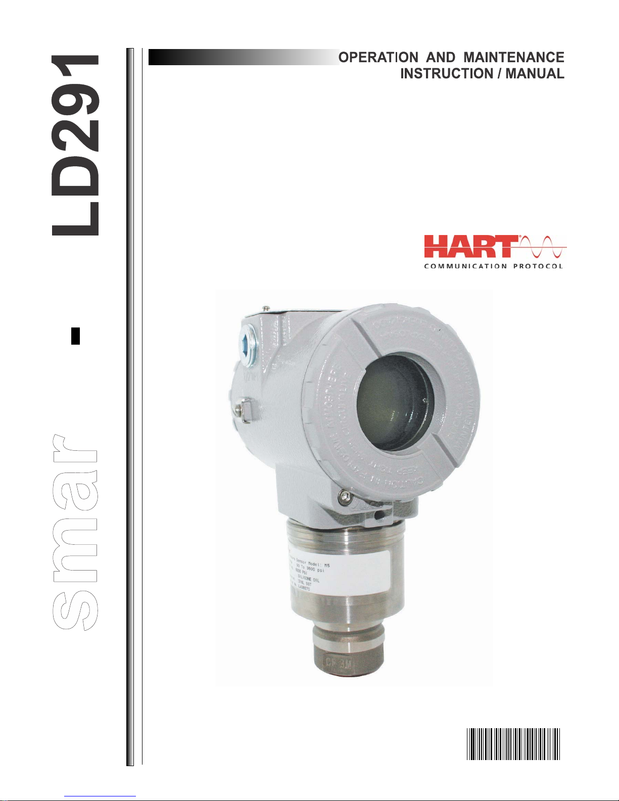
During normal operation, the LD291 is in the monitoring mode. In this mode, indic ation alternates
between the primary and secondary variable as configured by the user. See Figure. 2.5. The display
indicates engineering units, values and parameters simultaneously with most status indicators.
The monitoring mode is interrupted when the user does complete local adjustment.
The display is also capable of displaying an error and other messages (See table 2.1).
TABLE FUNCTION
INDICATES ACTIVE
CONSTANT OUTPUT MODE
INDICATES POSSIBILITY
TO ADJUST / CHANGE
VARIABLES / OPTIONS
MD
Fix
F(x)
PV
Figure 2.4 - Display
%
INDICATES ACTIVE
MULTIDROP MODE
VARIABLE FIELD
UNIT PERCENT
UNIT AND FUNCTION FIELD
VARIABLE IS NOW DISPLAYED
2.5
LD291- Operation and Maintenance Instruction Manual
CHAR
LD291
Figure 2.5 – Typical Monitoring Mode Display Showing PV, in this case 25.00 mmH20
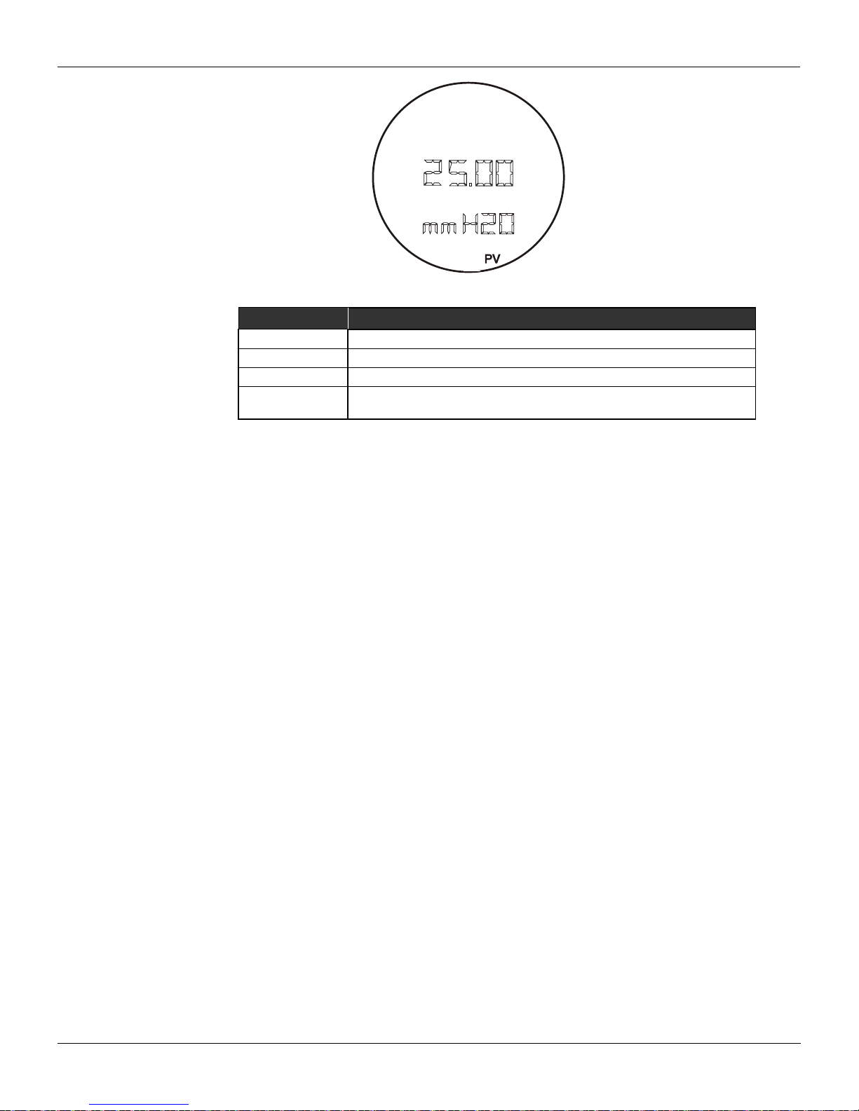
DISPLAY DESCRIPTION
INIT The LD291 is in initializing after power on.
FAIL SENS
SAT
The
Sensor failure. Refer to Section 5 - Maintenance.
Current output saturated in 3.8 or 20.5 mA. See Section 5 –
Maintenance.
is characterization mode. See Section 3 – Trim.
Table 2.1 - Display Messages
2.6

Section 3
k configuration for classified areas, the entity parameters a llow ed f or
≤
CONFIGURATION
The LD291 Intelligent Pressure T ransmitter is a digital instrument with the most up-to-date features a
measurement device can possibly have. Its digital communication protocol (HART
instrument to be connected to a computer in order to be configured in a very simple and compl ete w ay .
Such computers connected to the transmitters are called HOST comp uters . T hey can e ither be Prima ry
or Secondary Masters. Therefore, even the HART
being a master-slave t ype of protocol, it is po ssible
to work with up to two masters in a bus. The Primary HOST plays the supervisory role and the
Secondary HOST plays the Configurator role.
The transmitters may be connected in a point-to-point or multidrop type network. In a point-to-point
connection, the equipment must be in its "0" address so that the output current may be modulated in 4
to 20 mA, as per the meas urement. In a multidrop network, if the devices are recognized by their
addresses, the transmitters shall be configured with a network address between "1" and "15. In this
case, the transmitter’s output current is kept constant, with a consumption of 4 mA each. If the
acknowledgement mechanism is via Tag, the transmitter’s addresses may be "0" while their output
current is still being controlled, even in a multidrop configuration.
In the case of the LD291 the "0" address causes the LD291 to control its output current and addresses
"1" through "15" place the LD291 in the multidrop mode with current control.
NOTE
In the case of multidrop networ
the area shall be strictly observed. Therefore, the following shall be checked:
Ca ≥ Σ Cij + Cc La ≥ Σ Lij + Lc
) enables the
Voc
Where:
min [Vmaxj] Isc ≤ min [Imaxj]
Ca, La - Barrier Allowable Capacitance and Inductance
Cij, Lij - Non protected internal Capacitance/Inductance of transmitter j (j = 1 up to 15)
Cc, Lc - Cable capacitance and Inductance
- Barrier open circuit voltage
V
oc
- Barrier short circuit current
I
sc
- Maximum allowable voltage to be applied to the instrument j
Vmax
j
- Maximum allowable current to be applied to the instrument j
Imax
j
The LD291 Intelligent Pressure Transmitter includes a very encompassing set of HART Command
functions that make it possible to access the functionality of what has been implemented. Such
commands comply with the HART
Common Practice Controls Commands and Specific Commands. A detailed description of such
commands may be found in the manual entitled HART
protocol specifications, and are grouped as Overall Commands,
Command Specification - LD291 Intelligent
Pressure Transmitter.
Smar developed the CONF401 and HPC301 software, the first one w orks in Windows pl atfo rm (95, 98,
2000, XP and NT) and UNIX. The second one, HPC301, works in the most recent technology in PD A´s.
They bring easy configuration and monitoring of field devices, capacity to analyze data and to modify
the action of these devices. The operation characteristics and use of each one of the
configurators are stated on their respective manuals.
Figures 3.1 and 3.2 show the front of the Palm and the CONF401 screen, with the active configur atio n.
3.1

LD291- Operation and Maintenance, Instruction manual
Figure 3.1 – Smar’s Configurator
3.2
Figure 3.2 – Screen of the Configurator

Configuration Features
By means of the HART
be accessed:
Transmitter Identification and Manufacturing Data;
Primary Variable Trim – Pressure;
Primary Variable Trim – Current;
Transmitter Adjustment to the Working Range;
Engineering Unit Selection;
Linearization Table;
Device Configuration;
Equipment Maintenance.
The operations, which take place between the configurator and the transmitter do not interrupt the
Pressure measurement, and do not disturb the output signal. The configurator can be connected on the
same pair of wires as the 4-20 mA signal, up to 2 km away from the transmitter.
Configurator, the LD291 firmware allows the following configuration features to
Manufacturing Data and Identification
The following information about the LD291 manufacturing and identification data is available:
TAG - 8 character alphanumeric field for identification of the transmitter;
DESCRIPTOR
- 16 character alphanumeric field for additional identification of the transmitter. May be
used to identify service or location;
DATE - The date may be used to identify a relevant date as the last calibration, the next calibration or
the installation. The date is presented in the form of bytes where DD = [1,..31], MM = [1..12], AA =
[0,..255], where the effective year is calculated by [Year = 1900 + AA];
MESSAGE - 32 character alphanumeric field for any other info rmati on, s uch a s: the name of the person
who made the last calibration, some special care to be taken, or if a ladder is needed for accessing;
INTEGRAL METER – Installed, Inert, Special, Unknown and None;
SENSOR FLUID* - Silicone, Inert, Special, Unknown and None;
SENSOR ISOLATING DIAPHRAGM* - 316 SST, Hastelloy C, Monel, Tantalum and Special;
SENSOR TYPE* - It shows the sensor type;
SENSOR RANGE* - It shows the sensor range in engineering units chosen by use r. See Configuration
Unit.
Items marked with asterisk cannot be changed. They are read directly from the sensor memory.
Primary Variable Trim - Pressure
Pressure, defined as a Primary Variable, is determined from the sensor readout by means of a
conversion method. This method uses parameters obtained during the fabrication process. They
depend on the electric and mechanical characteristics of the sensor, and on t he te mpera ture chan ge to
which the sensor is submitted. These parameters are recorded in the sensor's EEPROM memory.
When the sensor is connected to the transmitter, such information is made available to the transmitter's
microprocessor, which sets a relationship between the sensor signal and the measured pressure.
Sometimes, the pressure show n on the transmitter's display is different from the appl ied p ressu re. T his
may be due to several reasons, among which the following can be mentioned:
Configuration
NOTE
3.3

LD291- Operation and Maintenance, Instruction manual
Some users prefer to use this feature for zero elevation or suppression when the measurement
For better accuracy, the trim adjustment should be made in the lower and upper values of the
certify that you are working with a pressure standard with accuracy 0.03% or better, otherwise the
The transmitter mounting position;
The user's pressure standard differs from the factory standard;
Sensor's original characteristics shifted by overpressure, over temperature or by long-term drift.
refers to a certain point of the tank or tap (wet tap). Such practice, however, is not recommended
when frequent laboratory calibrations are required, because the equipment adjustment refers to a
relative measurement, and not to an absolute one, as per a specific pressure standard.
The Pressure Trim, as described on this document, is the method used in order to adjust the
measurement as related to the applied pressure, as per the user's pressure standard. The most
common discrepancy found in transmitters is usually due to Zero displacement. This may be c orrected
by means of the Zero Trim or the Lower Trim.
There are four types of pressure trim available:
LOWER TRIM: Is used to trim the reading at the lower range. The user informs to the transmitter
the correct reading for the applied pressure via HART configurator.
Check on section 1, the note on the influence of the mounting position on the indicator.
NOTE
NOTE
operation range values.
UPPER TRIM: Is used to trim the reading at the upper range. The user informs the transmitter the
correct reading for the applied pressure via HART
The upper pressure trim shall always be done after the zero trim.
ZERO TRIM: is similar to the LOWER TRIM , but is assumed that the applied pressure is zero. T he
reading equal to zero must be active when the pressures of differential transmitter cameras are
equalized or when a manometric transmitter opened to atmosphere or when the absolute
transmitter is applied to the vacuum. Therefore, the user does not need to enter with any value.
CHARACTERIZATION: this is used to correct an eventual non-linearity intrinsic to the conversion
process. Characterization is done by means of a linearization table, with up to five points. The user
shall apply pressure and use the HART
point of the table. In most cases, characterization is not required, due to the efficiency of the
fabrication procedure. The transmitter will display "CHAR", thus indicating that the characterization
process is activated. The LD291 has a parameter to enable or disable the use of the
Characterization Table.
The characterization trim changes the transmitter characteristics. Read the instructions carefully and
transmitter accuracy will be seriously affected.
Primary Variable Current Trim
When the microprocessor generates a 0 % signal, the Digital to Analog converter and associated
electronics are supposed to deliver a 4 mA output. If the signal is 100 %, the output should be 20 mA.
There might be differences between the Smar current standards and your plant current Standard. In
this case, the Current Trim adjustment shall be used, with a precision Ammeter as measurement
reference. Two Current Tri m types are available:
configurator.
ATTENTION
configurators to inform the pressure value applied to each
WARNING
3.4

4 mA TRIM: this is used to adjust the output current value corresponding to 0 % of the
The transmitter presents a resolution that makes it possible to control currents as low as
measurement;
20 mA TRIM: this is used to adjust the output current value corresponding to 100 % of the
measurement.
The Current Trim shall be carried out as per the following procedure:
Connect the transmitter to the precision Ammeter;
Select one of the Trim types;
W ait a moment for the current to stabilize and inform the transmitter the current readout of the
precision Ammeter.
NOTE
microamperes. Therefore, when informing the current readout to the transmitter, it is recommended
that data input consider values up to tenth of microamperes.
Transmitter Adjustment to the Working Range
This function directly affects the transmitter's 4-20 mA output. It is used to define the transmitter's
working range; in this document it is referred to as the transmitter' s calibration. The LD291 transmitter
includes two calibration features:
CALIBRATION WITH REFERENCE: this is used to adjust the transmitter's working range, using a
pressure standard as a reference.
CALIBRATION WITHOUT REFERENCE: this is used to adjust the transmitter's working range,
simply by having limit values informed by the user.
Both calibration methods define the Working Range Upper and Lower values, in reference to some
applied pressure or simply informed by entered values. CALIBRATION WITH REFERENCE differs
from the Pressure Trim, since CALIBRATION WITH REFERENCE establishes a relationship between
the applied pressure and the 4 to 20 mA signal, and the Pressure Trim is used to correct the
measurement value.
In the transmitter mode, the Lower Value always corresponds to 4 mA and the Upper Value to 20 mA.
In the controller mode, the Lower Value corresponds to PV = 0 % and the Upper Value to PV = 100 %.
The calibration process calculates the LOWER and the UPPER values in a completely independent
way. The adjustment of value does not affect the other. The following rules shall, however, be
observed:
The Lower and Upper values shall be within the range limited by the Minimum and maximum
Ranges supported by the transmitter. As a tolerance, values exceeding such limits by up to 24 %
are accepted, although with some accuracy degradation.
The Working Range Span, determined by modulus of the difference between the Upper and Lower
Values, shall be greater than the minimum span, defined by [Transmitter Range / 120]. Values up
to 0.75 of the minimum span are acceptable with slight accuracy degradation.
NOTE
If the transmitter is operating with a very small span, it will be extremely sensitive to pressure
variations. Keep in mind that the gain will be very high and any pressure change, no matter how
small, will be amplified.
If it is necessary to perform a reverse calibration, that is, to w ork with an UP PER VALUE smaller than
the LOWER VALUE, proceed as follows:
Place the Lower Limit in a value as far from the present Upper Value and from the new adjusted
Upper value as possible, observing the minimum span allowed. Adjust the Upper Value at the
desired point and, then, adjust the Lower Value.
This type of calibration is intended to prevent the calibration from reaching, at any moment, values not
compatible with the range. For example: lower value equals to upper value or separated by a value
smaller than the minimum span.
Configuration
3.5

LD291- Operation and Maintenance, Instruction manual
Unit feature for such conversion.
This calibration procedure is also recommended for zero suppr ession or elevation in those cases where
the instrument installation results in a residual measurement in relation to a certain reference. This is
the specific case of the wetted tap.
In most applications with wetted taps, indication is usually expres sed as a percentage. Should
readout in engineering units with zero suppression be required, it is recommended to use the User
Engineering Unit Selection
Transmitter LD291 includes a selection of engineering units to be used in measurement indication.
For pressure measurements, the LD291 includes an option list with the most common units. The
internal reference unit is inH2O @ 20 oC; should the desired unit be other than this one, it will be
automatically converted using conversion factors included in Table 3.1.
As the LD291 uses a 4 ½ digit display, the largest indication will be 19999. Therefore, when selecting a
unit, make sure that it will not require readouts greater than this limit. For User reference, Table 3.1
presents a list of recommended sensor ranges for each available unit.
CONVERSION FACTOR NEW UNITS RECOMMEND RANGE
1.00000 Inches H2O at 20 oC 1, 2,3 & 4
0.0734241 Inches Hg at 0 oC all
0.0833333 Feet H2O at 20 oC all
25.4000 Millimeters H2O at 20 oC 1 & 2
1.86497 Millimeters Hg at 0 oC 1, 2, 3 & 4
0.0360625 Pound/square inch - psi 2, 3, 4, 5 & 6
0.00248642 Bar 3, 4, 5 & 6
2.48642 Millibar 1, 2, 3 & 4
2.53545 Gram/square centimeter 1, 2, 3 & 4
0.00253545 kilogram/square centimeter 3, 4, 5 & 6
248.642 Pascal 1
0.248642 KiloPascal 1, 2, 3 & 4
1.86497 Torr at 0 oC 1, 2, 3 & 4
0.00245391 Atmosphere 3, 4, 5 & 6
0.000248642 MegaPascal 4, 5 & 6
0.998205 Inches of water at 4 oC 1, 2, 3 & 4
25.3545 Millimeters of water at 4 oC 1 & 2
In applications where the LD291 will be used to measure variables other than pressure or in the cases
where a relative adjustment has been selected, the new unit may be display ed by means of the User
Unit feature. This is the case of measurements such as level, volume, and flow rate or mass flow
obtained indirectly from pressure measurements.
The User Unit is calculated taking the working range limits as a reference, which is, defining a value
corresponding to 0% and another corresponding to 100% of the measurement:
0% - Desired readout when the pressure is equal to the Lower Value (PV% = 0%, or transmitter
mode output equal to 4 mA).
100% - Desired readout when the pressure is equal to the Upper Value (PV% = 100%, or
transmitter mode output equal to 20 mA).
The user unit may be selected from a list of options included in the LD291. Table 3.2 makes it possible
to associate the new measurement to the new unit so that all supervisory systems fitted with HART
protocol can access the special unit included in this table. The user will be responsible for the
consistency of such information. The LD291 cannot verify if the values corresponding to 0 % and 100%
included by the user are compatible with the selected unit.
NOTE
Table 3.1 - Available Pressure Units
3.6

VARIABLE
UNITS
Pressure
inH2O, InHg, ftH2O, mmH2O, mmHg, psi, bar ,mbar, g/cm2, kg/cm2 , Pa,
kPa, Torr, atm, MPa, in H2O4, mmH2O4
3
Gal/h, Gal/d, ft3/h, m3/min, bbl/s, bbl/min, bbl/h, bbl/d, gal/h, Gal/s, I/h, gal/d
Velocity
ft/s, m/s, m/h
Volume
gal, liter, Gal, m3, bbl, bush, Yd3, ft3, In3, hl
Level
ft, m, in, cm, mm
Mass
gram, kg, Ton, lb, Sh ton, Lton
g/s, g/min, g/h, kg/s, kg/min, kg/h, kg/d, Ton/min, Ton/h, Ton/d, lb/s, lb/min,
lb/h, lb/d
SGU, g/m3, kg/m3, g/ml, kg/l, g/l, Twad, Brix, Baum H, Baum L, API, %
Solw, % Solv, Ball
Others
cSo, cPo, mA, %
special
5 characters
POINT
LEVEL (PRESSURE)
X
VOLUME
Y
1 - -10%
-
-0.62%
2
250 mmH2O
0%
0 m3
0%
3
450 mmH2O
10%
0.98 m3
5.22%
4
750 mmH2O
25%
2.90 m3
15.38%
5
957.2 mmH2O
35.36%
4.71 m3
25%
6
1050 mmH2O
40%
7.04 m3
37.36%
7
1150 mmH2O
45%
8.23 m3
43.65%
8
1250 mmH2O
50%
9.42 m3
50%
… … … … …
15
2250 mmH2O
100%
18.85 m3
100%
16 - 110%
-
106%
Volumetric Flow
Mass Flow
Density
Configuration
/min, gal/min, I/min, Gal/min, m3/h, gal/s, l/s, MI/d, ft3/s, ft3/d, m3/s, m3/d,
ft
Table Points
Table 3.2 – Available User Units
Should a special unit other than those presented on Table 3.2 be required, the LD291 allows the user
to create a new unit by entering up to 5 alphanumeric digits.
The LD291 includes an internal feature to enable and disable the User Unit.
Example: transmitter LD291 is connected to a horizontal cylindrical tank (6 meters long and 2 meters
in diameter), linearized for volume measurement using camber table data in its linearization table.
Measurement is done at the high-pressure tap and the transmitter is located 250 mm below the support
base. The fluid to be measured is water at 20 °C. Tank volume is: [(π.d
2
)/4].l = [(π.22)/4]π.6 = 18,85 m3.
The wet tap shall be subtracted from the measured pressure in order to obtain the tank level.
Therefore, a calibration without reference shall be carried out, as follows:
In Calibration:
Lower = 250 mmH
Superior = 2250 mmH
Pressure unit = mmH
O
2
O
2
O
2
In User Unit:
User Unit 0% = 0
User Unit 100% = 18.85 m³
User Unit = m³
When activating the User's Unit, LD291 it will start to indicate the new measurement.
If the option TABLE is selected, the output will follow a curve given in the option TABLE P OINTS . If you
want to have your 4-20 mA proportional to the volume or mass of fluid inside a tank, you must
transform the pressure measurement "X" into volume (or mass) "Y" using the tank strapping table, as
shown in Table 3.3.
As shown on the previous ex ample, the points may be freely distributed for any desired value of X . In
order to achieve a better linearization, the distribution should be concentrated in the less l inear part s of
the measurement.
Table 3.3 - Tank Strapping Table
3.7

LD291- Operation and Maintenance, Instruction manual
The LD291 includes an internal feature to enable and disable the Linearization Table.
Equipment Configuration
The LD291 enables the configuration of not only its operational services, but of instrument itself. This
group includes services related to: Input Filter, Burn Out, Addressing, Display Indication and
Passwords.
INPUT FILTER - The Input Filter, also referenced to as Damping, is a first class digital filter
implemented by the firmware, where the time constant may be adjusted between 0 and 128
seconds. The transmitter's mechanical damping is 0.2 seconds.
BURN OUT - The output current may be programmed to go to the maximum limit of 21 mA (Full
Scale) or to the minimum limit of 3.6 mA in case of transmitter failure. Configuring the BURNOUT
parameter for Upper or Lower may do this.
ADDRESSING - The LD291 includes a variable parameter to define the equipment address in a
DISPLAY INDICATION - the LD291 digital display is comprised of three distinct fields: an
HART
network. Addresses may go from value "0" to "15"; addresses from "1" to "15" are specific
addresses for multidrop connections. This means that, in a multidrop configuration, the LD291 will
display the message MDROP for addresses "1" to "15".
The LD291 is factory configured with address "0".
information field with icons indicating the active configuration stat us, a 4 ½ digit numeric field for
values indication and a 5 digit alphanumeric field for units and status information.
The LD291 may work with up to two display configurations to be alternately display ed at 2 second
intervals. Parameters that may be selected for visualization are those listed on Table 3.4, below.
WRITING PROTECTION - This feature is used to protect the transmitter configuration from
changes via communication. All configuration data are writing protected.
The LD291 include two write protection mechanisms: software and hardware locking; software
locking has higher priority.
When the LD291 writing software protection mechanism is enabl ed, it is possible, by means of
specific commands, to enable or disable the write protection.
PASSWORDS - this service enables the user to modify the operation passwords used in the
LD291. Each password defines the access for a priority level (1 to 3); such configuration is stored
in the LD291 EEPROM.
Password Level 3 is hierarchically upper to password level 2, which is upper to level 1.
Equipment Maintenance
Here are grouped maintenance services related with the collection of information required for
equipment maintenance. The following services are available: Order Code, Serial Number, O peration
Counter and Backup/Restore.
ORDER CODE - THE Order Code is the one used for purchasing the equipment, in accordance
with the User specification. There are 13 characters available in the LD291 to define this code.
CURRENT
CURRENT IN MILIAMPÈRES
CO Analog Output Current in mA
PR Pressre in pressure unit.
PV% Process Variable in percentage.
PV Process Variable in engineering units.
TE Ambient temperature.
NONE - No variable on display (only LCD_2)
ESC Escape.
Table 3.4 - Variables for Display Indication
3.8

11 12
EXAMPLE:
Configuration
1 2 3 4 5 6 7 8 9 10
13
L D 2 9 1 M 2 1I 1 1 0 1 H1
LD291 Intelligent Pressure Transmitter (D); Range: 1.25 to 50 kPa (2); Diaphragm of 316L SS,
Silicone Oil Fill Fluid (1), and Connection to the process with 316L SS (1I); with Digital Indicator (1);
Electrical Connection 1/2 - 14 NPT (0); with Local Adjustment (1); with Carbon Steel Bracket and
accessories (1); housing in SS (HI).
SERIAL NUMBER - Three serial numbers are stored:
Circuit Number - This number is unique to every main circuit board and cannot be changed.
Sensor Number - The serial number of the sensor connected to the LD291 and cannot be
changed. This number is read from the sensor every time a new sensor is inserted in the main
board.
Transmitter Number - the number that is written at the identification plate each transmitter.
NOTE
The transmitter number must be changed whenever there is the main plate change to avoid
communication problems.
OP_COUNT - Every time a change is made, there is an increment in the respective change
counter for each monitored variable, according to the following list. The counter is cyclic, from 0 to
255. The monitored items are:
LRV/URV: when any type of calibration is done;
Function: when any change in the transference function is done, e.g., linear, square root,
const, table;
Trim_4mA: when the current tri m i s done at 4 mA;
Trim_20mA: when the current tri m i s done at 20 mA;
Trim_Zero/Lower: when pressure trim is done at Zero or Lower Pressure;
Trim Upper Pressure: when the trim is done at Upper Pressure;
Characterization: when any change is made in any point of the pressure ch aracterization table
in trim mode;
Multidrop: when any change is made in the communication mode, for example, multidrop or
single transmitter;
Pswd/C-Level: when any change is made in the password or the level configuration.
BACKUP
When the main board is replaced, after assembling and powering it, the data saved in the sensor
memory are automatically copied to the main board memory.
RESTORE
This option allows copying or restoring the data saved in the sensor memory to the main board
memory.
3.9

LD291- Operation and Maintenance, Instruction manual
3.10

Section 4
COMPLETE
ADJUSTMENT
S - ACTION / SPAN
Z - MOVE AROUND / ZERO
The Magnetic Tool
PROGRAMMING USING LOCAL
ADJUSTMENT
Smar's magnetic tool is the second man machine interface. It comprises the advantage of the po werf ul
HHT and the convenience of the magnetic tool.
If the transmitter is fitted with a display, and configured for Complete Local Adjustment (using the
internal jumper), the magnetic tool is almost as powerful as the HHT. It eliminates the need for an H HT
in most basic applications.
If the transmitter is not fitted with a display, or is configured for Simple Local Adjustment (using the
internal jumper) the adjustment capability is reduced to ranging.
To select the function mode of the magnetic switches configures the jumpers located at the top of the
main circuit board as indicated in Table 4.1.
SI/COM OFF/ON NOTE WRITE PROTECT
SIMPLE LOCAL
ADJUSTMENT
LOCAL
Notes: 1 - If t he har dware protection is selected, the EEPROM will be protect ed.
2 - The local adjustment default condition is simple enabled and write protect disabled.
The transmitter has, under the identification plate, holes for two magnetic switches activated by the
magnetic tool (See Figure 4.1).
Disables Disables Disables
1 Enables
2
Disables Disables Enables
Table 4.1 – Local adjustment Selection
Disables
Disables Disables
Enables
Disables
Figure 4.1 – Local Zero and Span Adjustment and Local Adjustment Switches
4.1

LD291 - Operation and Maintenance Instruction Manual
Z
The holes are marked with Z (Zero) and S (Span) and from now on w ill be designated si mply by (Z) and
(S), respectively. Table 4.2 shows the action performed by the magnetic tool while inserted in (Z) and
(S) in accordance with the selected adjustment type.
Browsing the functions and their branches works as follows:
1. Inserting the handle of the magnetic tool in (Z), the transmitter passes from the normal
measurement state to the transmitter configuration state. The transmitter software automatically
starts to display the available functions in a cyclic routine.
2. In order to reach the desired option, browse the options, wait until they are disp layed and move the
magnetic tool from (Z) to (S). Refer to Figure 4.2 – Programming Tree Using Local Adjustment, in
order to know the position of the desired option. By placing the magnetic too l onc e aga in in (Z), it is
possible to browse for other options within this new branch.
3. The procedure to reach the desired option is similar to the one described on the previous item, for
the whole hierarchical level of the programming tree.
Action Simple Local Adjustment Complete Local Adjustment
S
For LD291 versions prior to a V6.00, the digital display shall be number 214-0108 as per spare
parts list for LD291 V6.XX.
For LD291 versions V6.XX, the digital display shall be number 400-0559, as per the updated
spare parts list
Simple Local Adjustment
The LD291 allows only the calibration of the values inferior and superior in this configuration.
Zero and Span Reranging
The LD291 can be very easily calibrated. It requires only Zero and Span adjustment in accordance with
the working range.
The jumpers shall be configured for simple local adjustment. In case the LD291 display is not
connected, the simple local adjustment is automatically activated.
Zero calibration with reference shall be done as follows:
Apply the Lower Value pressure.
Wait for the pressure to stabilize.
Insert the magnetic tool in the ZERO adjustment hole. (See Figure 4.1)
Wait about 2 seconds. The transmitter should be reading 4 mA.
Remove the tool.
Zero calibration with reference does not affect the span. In order to change the span, the following
procedure shall be observed:
Apply the Upper Value pressure.
Wait for the pressure to stabilize.
Insert the magnetic tool in the SPAN adjustment hole.
Wait 2 seconds. The transmitter should be reading 20 mA.
Remove the tool.
Zero adjustment causes zero elevation / suppression and a new upper value (URV) is calculated in
accordance with the effective span. In case the resulting URV is higher than the Upper Limit Value
(URL), the URV will be limited to the URL value, and the span will be automatically affected.
Selects the Lower Range Value Moves among all the options
Selects the Upper Range Value Activates the selected Functions
Table 4.2 - Local Adjustment Description
NOTE
4.2

Complete Local Adjustment
op to manual. And do not forget to return to auto after
Z
S
Z
NORMAL
DISPLAY
ACTION
S
Z
MOVE
AROUND
Z
ESC
ESCAPE
The transmitter must be fitted with the digital display for this function to be enabled. The following
functions are available for local adjustment: Constant Current, Table Points Adjustment, User Units,
and Fail-safe, Current Trim and Pressure, Address change and some items of function INFORMATION.
When programming using local adjustment, the transmitter wil l not pro mpt, "Control loop should be
in manual!" as it does when programming using the HART
before configuration, to switch the lo
configuration is completed.
Local Programming Tree
The local adjustment uses a tree structure where, by placing the magnetic tool in (Z) it is possible to
browse the options of a branch and by placing it in (S); details of the chosen option are shown. Figure
4.2 shows the LD291 available options.
WARNING
Programming Using Local adjustment
configurator. Therefore it is a good idea,
CONFIGURATION (CONF) - Is the option where the output and display related parameters are
configured: unit, primary and secondary display, calibration, and function.
TRIM (TRIM) – It is the option used to calibrate the "w ithout reference" characterization and the digital
reading.
ESCAPE (ESC) – It is the option used to go back to normal monitoring mode.
The local adjustment is actived by actuation in (Z).
Configuration [CONF]
Configuration functions affect directly the 4-20 mA output current and the display indication. The
configuration options implemented in this branch are the following:
Selection of the variable to be shown on Display 1 and / or Display 2;
Working range calibration of work. Options With and Without Reference are available;
Digital filter damping time configuration of the readout signal input.
Selection of the transference function to be applied to the measured variable.
Figure 4.2 – Local Adjustment Programming Tree – Main Menu
4.3

LD291 - Operation and Maintenance Instruction Manual
Figure 4.3 shows branch CONF with the available options.
Configuration Branch (CONF)
Display 1 (LCD_1)
Display 2 (LCD_2)
The procedure for selection is the same as for LCD_1, previous.
4.4
Figure 4.3 - Local Adjustment Configuration Tree
Z: Moves to the TRIM branch.
S: Enters the CONFIGURATION branch, starting with function display (LCD_1).
Z: Moves to the function Display 2 (LCD_2).
S: Starts selection of variable to be indicated as primary display.
After activating (S), you can move around the options available in t he following
table by activating (Z). See table 4.3.
The desired variable is activated using (S). Escape leaves primary variable
unchanged.
Z: Moves to the RANGE function.
S: Starts selection of variable to be indicated as secondary display.
CURRENT
CURRENT IN MILIAMPÈRES
CO Analog Output Current in mA
PR Pressre in pressure unit.
PV% Process Variable in percentage.
PV Process Variable in engineering units.
TE Ambient temperature.
NONE - No variable on display (only LCD_2)
ESC Escape.
Table 4.3 - Display Indication

Range (RANGE)
Programming Using Local adjustment
Function Calibration (RANGE) presents the calibration options as a tree branch, as described on
Figure 4.4.
Figure 4.4 – Local Range Tree
Range Branch (RANGE)
Unit (UNIT)
* The Torr unit has been changed to mH2O@20 ºC for version 6.04 or greater.
Z: Moves to the FUNCT function from range branch.
S: Enters the RANGE branch, starting with the function UNIT.
Z: Moves to the LRV function.
S: Starts selection of engineering unit for process variable. After activ ating (S),
you can move around the options available in the table below by activating (Z).
Using (S) activates the desired unit. Escape leaves the unit unchanged.
UNIT
DISPLAY DESCRIPTION
InH2O Inches water column at 20 oC
InHg Inches mercury column at 0 oC
ftH2O Feet water column at 20 oC
mmH2O Millimeter water column at 20 oC
mmHg Millimeter mercury column at 0 oC
psi Pounds per square centimeter
Bar Bar
Mbar Millibar
g/cm2 Grams per square centimeter
k/cm2 Kilograms per square centimeter
Pa Pascals
kPa Kilo Pascals
Torr* Torr at 0 oC
atm Atmospheres
ESC Escape
Table 4.4 – Units
4.5

LD291 - Operation and Maintenance Instruction Manual
Lower Range Value Adjustment without Reference (LRV)
Z: Moves to the LRV DECREASE function.
S: Increases the Lower Value until the magnetic tool is removed or the
maximum limit for the Lower Value is reached.
Z: Moves to the URV ADJUSTMENT function.
S: Decreases the Lower Value until the magnetic tool is r emov ed or the minim um
limit for the Lower Value is reached.
Upper Range Value Adjust without Reference (URV)
Z: Moves to the URV DECREASE function.
S: Increases the Upper Value until the magnetic tool is removed or the
maximum limit for the Upper Value is reached.
Z: Moves to the ZERO ADJUSTMENT function.
S: Decreases the Upper Value until the magnetic tool is removed or the minimum
limit for the Upper Value is reached.
Zero Adjust with Reference (ZERO)
Z: Moves to the ZERO DECREASE function.
S: Increases output in transmitter mode, decreases the Lower Pr essure Value
until the magnetic tool is removed or the maximum limit for the Lower Value is
reached. The span is maintained.
Z: Moves to the SPAN ADJUSTMENT function.
S: Decreases Output in transmitter mode, increases the Lower Pressure Value
until the magnetic tool is removed or the minimum limit for the Lower Value is
reached. The span is maintained.
Span Adjust with Reference (SPAN)
Z: Moves to the SPAN DECREASE function.
S: Increases the Output in transmitter mode, decreases the Upper Pressure
Value until the magnetic tool is removed or the maximum limit for the Upper
Value is reached.
4.6

Function (FUNCT)
Z: Moves to the DAMPING function.
S: Decreases the Output in transmitter mode, increases the Upper Pressure
Value until the magnetic tool is removed or the minimum limit for the Upper
Value is reached.
Damping (DAMP)
Z: Moves to the DAMPING DECREASE function.
S: Increases the damping time constant until the magnetic tool is removed or
128 seconds are reached.
Z: Moves to the SAVE function.
S: Decreases the damping time constant until the magnetic tool is removed or 0
second is reached.
Save (SAVE)
Z: Moves to the ESCAPE of RANGE menu.
S: Saves the LRV, URV, ZERO, SPAN and DAMP values in the transmitter
EEPROM.
Escape (ESC)
Z: Moves to the UNIT function.
S: Moves to the FUNCT menu, of the MAIN menu.
Z: Moves to the ESCAPE function.
S: Starts selection of input function. After activating (S) you can move around
the available options in the table below by activating (Z).
DISPLAY DESCRIPTION
LINE Linear to Pressure.
TABLE 16 Point Table.
ESC ESC to Escape from the superior Branch.
FUNCTIONS
Table 4.5 – Functions
Programming Using Local adjustment
4.7

LD291 - Operation and Maintenance Instruction Manual
PROTECTED BY PASSWORD. THE PASSWORD CODE IS SIMILAR
THAT DE SCRIBED FOR THE OPERATION (MODE), IN THE PAGE 4.11.
SAVE ESC
z
z
s
s
UPPER
s s
z z
UPPER
ZERO
s
z
LOWER
s
z
s
z
LOWER
TRIM * ESC
s
z
The desired function is activated using (S). Escape leaves function unchanged.
Z: Recycles for menu LCD – 1.
S: Moves to the CONF function of the main menu.
Pressure Trim [TRIM]
This field of the tree is used to adjust the digital reading according to the applied pressure. The
pressure TRIM differs from RANGING WITH REFERENCE, since the TRIM is used to correct the
measure and RANGING WITH REFERENCE reach only the applied pr essure with the output signal of
4 to 20 mA.
Figure 4.5 shows the options available to run the pressure TRIM.
Figure 4.5 – Pressure Trim Tree
Trim Branch (TRIM)
Z: Moves to ESC function.
S: These functions are protected by a "password." When prompted PSWD
activates (S) 2 times to proceed. After entering the password, the TRI M b ranch
starting with the Zero Trim function is accessed.
NOTE
Check on section 1, the note on the influence of the mounting position on the indicator. For better
accuracy, the trim adjustment should be made in the lower and upper values of the operation range
values.
Zero Pressure Trim (ZERO)
Z: Moves to the LOWER pressure TRIM function.
S: Trims the transmitters' internal reference to read 0 at the applied pressure.
4.8

Lower Pressure Trim (LOWER)
Z: Moves to o ption DECREASES THE LOWER PRESSURE VALUE.
S: Adjusts the transmitter's internal reference, increasing the displayed value
that will be interpreted as the Lower Pressure value corresponding to the
applied pressure.
Z: M oves on to function SAVE if the Lower Pr essure Trim (LOWER) is running
or to the Upper Pressure Trim (UPPER).
S: Adjusts the transmitter's internal refer ence, decreasing the displayed value
that will be interpreted as the Lower Pressure value corresponding to the
applied pressure.
Upper Pressure Trim (UPPER)
Z: Moves to the decrease Upper Pressure reading.
S: Sets the transmitters' internal reference increasing to the value on the
display, which is the reading of the applied pressure.
Z: Moves to the SAVE function.
S: Sets the transmitters' internal reference decreasing to the value on the
display, which is the reading of the applied pressure.
Z: Moves to the ESCAPE from TRIM menu.
S: Saves the LOWER and UPPER TRIM point in the transmitter EEPRO M and
actualize the internal parameters pressure measurement.
Escape (ESC)
Z: Moves to the ZERO TRIM function.
S: Escapes to the MAIN menu.
Programming Using Local adjustment
4.9

LD291 - Operation and Maintenance Instruction Manual
Escape Local Adjustment [ESC]
This branch of the main tree is used to leave the Local Adjustment mode, placing the Transmitter or
Controller in the monitoring mode.
Z: Selects the OPERATION branch.
S: Escapes to NORMAL DISPLAY mode.
4.10

Section 5
NOTE
Equipments installed in hazardous atmospheres must be inspected in compliance with the
IEC60079-17 standard.
MAINTENANCE PROCEDURES
General
SMAR LD291 intelligent pressure transmitters are extensively tested and inspected before delivery to
the end user. Nevertheless, its design includes additional information for diagnosis purposes, in order
to provide an easier fault detection capability and, as a consequence, an easier maintenance.
In general, it is recommended that end users do not try to repair printed circuit boards. Spare circuit
boards may be ordered from SMAR whenever necessary.
The sensor has been designed to operate for many years without malfunctions. Should the process
application require periodic cleaning of the transmitter, the flanges may be easily removed and
reinstalled.
Should the sensor eventually require maintenance, it may not be changed in the field. In this case, the
possibly damaged sensor should be returned to SMAR for evaluation and, if necessary, repair. Refer to
the item "Returning Materials" at the end of this Section.
Diagnostic with the Configurator
Error Messages
ERROR MESSAGES POTENTIAL SOURCE OF PROBLEM
UART RECEIVER FAILURE:
• PARITY ERROR
• OVERRUN ERROR
• ERROR CHECK SUM
• FRAMING ERROR
CONFIGURATOR RECEIVES NO
ANSWER FROM TRANSMITTER
CMD NOT IMPLEMENTED
TRANSMITTER BUSY
XMTR MALFUNCTION
Should any problem be noticed relating to the transmitter output, the configurator may carry out
investigation, as long as power is supplied and communication and the processing unit are operating
normally (see Table 5.1).
The configurator should be connected to the transmitter according to the wiring diagram shown on
Section 1, Figures 1.10 and 1.11.
When communicating using the CONFIGURATOR the user will be informed about any problem found
by the transmitter self-diagnostics.
Table 5.1 presents a list of error messages with details for corrective actions that may be necessary .
• The line resistance is not according to load curve.
• Excessive noise or ripple in the line.
• Low level signal.
• Interface damaged.
• Power supply with inadequate voltage.
• Transmitter line resistance is not according to load curve;
• Transmitter not powered;
• Interface not connected or damaged;
• Repeated bus address;
• Transmitter polarity is reversed;
• Interface damaged;
• Power supply with inadequate voltage.
• Software version not compatible between configurator and transmitter.
Configurator is trying to carry out a LD291 specific command in a transmitter from
another manufacturer.
• Transmitter carrying out an important task, e.g., local adjustment.
• Sensor disconnected.
• Sensor failure.
5.1

LD291 - Operation and Maintenance Instruction Manual
LOWER RANGE VALUE TOO
LOWER RANGE VALUE TOO
UPPER & LOWER RANGE
PASSED PARAMETER TOO
PASSED PARAMETER TOO
ERROR MESSAGES POTENTIAL SOURCE OF PROBLEM
COLD START
OUTPUT FIXED
OUTPUT SATURATED
SV OUT OF LIMITS
PV OUT OF LIMITS
• Start-up or Reset due to power supplies failure.
• Output in Constant Mode.
• Transmitter in Multidrop mode.
• Pressure out of calibrated Span or in fail-safe state (Output current in 3.8 or 20.5 mA).
• Temperature out of operating limits.
• Temperature sensor damaged.
• Pressure out of operation limits.
• Sensor damaged or sensor module not connected.
• Transmitter with false configuration.
HIGH
LOW
UPPER RANGE VALUE TOO HIGH
UPPER RANGE VALUE TOO L OW
VALUES OUT OF LIMITS
SPAN TOO SMALL
APPLIED PRESURE TOO HIGH
APPLIED PRESURE TOO LOW
EXCESS CORRECTION
LARGE
SMALL
• Lower value exceeds 24% of the Upper Range Limit.
• Lower value exceeds 24% of the Lower Range Limit.
• Upper value exceeds 24% of the Upper Range Limit.
• Upper value exceeds 24% of the Lower Range Limit.
• Lower and Upper Values are out of the sensor range limits.
• The difference, between the Lower and U pper values is less than the 0.75 x (minimum
span).
• The pressure applied was above the 24% upper range limit.
• The pressure applied was below the 24% lower range limit.
• The trim value entered exceeded the factory-characterized value by more than 10%.
• Parameter above operating limits.
• Parameter below operating limits.
Table 5.1 - Error Messages and Potential Source
Diagnostic with the Transmitter
Symptom: NO LINE CURRENT
Probable Source of Trouble:
Transmitter Connections
• Check wiring polarity and continuity;
• Check for shorts or ground loops;
• Check if the power supply connector is connected to main board.
Power Supply
• Check power supply output. The voltage must be between 12 and 45 Vdc at transmitter
terminals.
Electronic Circuit Failure
• Check the main board for defect by using a spare one.
Symptom: NO COMMUNICATION
Probable Source of Trouble:
Terminal Connections
5.2

Maintenance Procedure
• Check the terminal interface connection of the configurator.
• Check if the interface is connected to the wires leading to the transmitter or to the terminals [+]
and [
- ].
• Check if the interface is models IF3 (for Hart protocol).
Transmitter Connections
• Check if connections are according to wiring diagram.
• Check if there is resistance in the 250 Ω line.
Power Supply
• Check output of power supply. The voltage at the LD291 terminals must be between 12 and 45
Vdc, and ripple less than 500 mV.
Electronic Circuit Failure
• Locate the failure by alternately testing the transmitter circuit and the interface w ith spar e par ts.
Transmitter Address
• Check if the transmitter address is compatible with the one expected by the configurator.
Symptom: CURRENT OF 21.0 mA or 3.6 mA
Probable Source of Trouble:
Pressure Tap (Piping)
• Verify if blocking valves are fully open;
• Check for gas in liquid lines or for liquid in dry lines;
• Check the specific gravity of process fluid;
• Check process flanges for sediments;
• Check the pressure connection;
• Check if bypass valves are closed;
• Check if pressure applied is not over upper limit of transmitter's range.
Sensor to Main Circuit Connection
• Check connection (male and female connectors).
Electronic Circuit Failure
• Check the sensor circuit for damage by replacing it with a spare one.
• Replace sensor.
Symptom: INCORRECT OUTPUT
Probable Source of Trouble:
Transmitter Connections
Check power supply voltage.
•
• Check for intermittent short circuits, open circuits and grounding problems.
Noise Measurement Fluid
Adjust damping
•
Pressure Tap
Check for gas in liquid lines and for liquid in steam or gases lines.
•
• Check the integrity of the circuit by replacing it with a spare one.
5.3

LD291 - Operation and Maintenance Instruction Manual
To avoid damage do not rotate the electronic housing more than 270º starting from the fully threaded
Calibration
• Check calibration of the transmitter.
A 21.0 or 3.6 mA current indicates that the transmitter is in Burnout (TRM) or safety output . Use the
configurator to investigate the source of the problem.
Symptom: DISPLAY INDICATES "FAIL SENS"
Probable Error Source:
Sensor Connection to the Main Board
Check the connection (flat cable, male and female connectors).
Type of Sensor Connected to the Main Board
Check if the sensor connected to the main board is the one specified for the LD291 model:
sensor type shall be hyper - High Performance.
Electronic Circuit Failure
Check if the sensor set is damaged, replacing it for a spare one.
Disassembly Procedure
Do not disassemble with power on.
Figure 5.3 shows transmitter's exploded view and will help you to visualize the following:
SENSOR
In order to have access to the sensor (18) for cleaning purposes, the transmitter should be removed
from its process connections.
Loosen the hex screw (8) and carefully unscrew the electronic housing from the sensor, observing that
the flat cable is not excessively twisted.
NOTE
WARNING
WARNING
without disconnecting the electronic circuit from the sensor and from the power supply. See Figure
5.1.
Figure 5.1 – Safety Housing Rotation
ELECTRONIC CIRCUIT
To remove the circuit board (6), loosen the two screws (5) that anchor the board and hold the (7)
spacers in the other side to avoid losing them.
5.4

The board has CMOS components, which may be damaged by electrostatic discharges. Observe
correct procedures for handling CMOS components. It is also recommended to store the circuit
boards in electrostatic-proof cases.
Pull the main board out of the housing and disconnect the power supply and the sensor connectors.
Reassembly Procedure
Do not assemble with power on.
SENSOR
When mounting the sensor (18), it is recommended to make use of a new set of gaskets (17)
compatible with the process fluid.
O’rings should be lightly lubricated with silicone oil before they are fitted into their recesses. Use
halogen grease for inert fill applications.
The fitting of the sensor must be done with the main board out of the electronic housing. Mount the
sensor to the housing turning it clockwise until it stops. Tighten the screw (8) to lock the body to the
sensor.
ELECTRONIC CIRCUIT
Plug sensor connector and power supply connector to main board. If there is a display, attach it to the
main board by means of 4 screws (3). The display can be installed in any of the 4 possible
positions(See Figure 5.2).
The ”
Pass the screws (5) through the main board holes (6) and the spacers (7) as shown on F igure 5.3 and
tighten them to the body.
Maintenance Procedure
WARNING
WARNING
” mark indicates up position.
After tightening the protective cover (1), mounting procedure is complete. The transmitter is ready to be
energized and tested. It is recommended that adjustment be done on the ZERO TRIM and on the
UPPER PRESSURE TRIM.
Interchangeability
In order to obtain an accurate and better temperature compensated response, each sensor is
submitted to a characterization process and the specific data is stored in an EEPROM located in the
sensor body.
Figure 5.2 – Four Possible Positions of the Display
5.5

LD291 - Operation and Maintenance Instruction Manual
The main board, in this operation, reads the sensor serial number and compares it with the number
stored in the main board. In case they do not match, the circuit considers that the sensor has been
changed and will probe the memory of the new sensor for the following information:
Temperature compensation coefficients;
Sensor trim data, including 5-point characterization curve;
Sensor characteristics: type, range, diaphragm material and fill fluid.
Information not transferred during sensor replacement will remain unchanged in the main board
memory. Thus, information such as Upper Value, Lower Value, Damping, Pressure Unit and
replaceable transmitter parts (Flange, O-ring, etc.) shall be updated, depending whether the correct
information is that of the sensor or the main board. In the case of a new sensor, the main board will
have the most updated information about the process; in the opposite case, the sensor will have it.
Depending on the situation, the updating shall be from one or the other.
Data transference from the main board to the sensor or vice versa, can also be forced by function
BACKUP/RESTORE from sensor.
Returning Materials
Should it become necessary to return the transmitter and/or configurator to SMAR, simply contact our
office, informing the defective instrument serial number, and return it to our factory.
If it becomes necessary to return the transmitter and/or configurator to Smar, simply contact ou r of fice,
informing the defective instrument's serial number, and return it to our factory. In order to speed up
analysis and solution of the problem, the defective item should be returned with the Serv ice Request
Form (SRF – Appendix B) properly filled with a description of the failure observed and with as much
details as possible. Other information concerning to the instrument operation, such as service and
process conditions, is also helpful.
Instruments returned or to be revised outside the guarantee term should be accompanied by a
purchase order or a quote request.
5.6

Maintenance Procedure
16
18
6
8
9
10
11
12
13
14
15
17
5
1
2
3
4
7
19
ORDERING CODE DESCRIPTION
SD-1 Magnetic Tool for local adjustment.
Palm 8 Mbytes Palm Handheld, including installation and initialization software for the
HPC301-SF1-V
HPI311-V HART
HPC301.
HART® Interface HPI311-V for Palm, including the configuration package for Smar
transmitters and for third parties transmitters.
Figure 5.1 – Exploded View
ACCESSORIES
®
interface.
5.7

LD291 - Operation and Maintenance Instruction Manual
1/2 NPT Internal Hexagon Plug in Plated CS BR Ex d.
PG13.5 External Hexagon Plug in 316 SST BR Ex d.
19
19
400-0808
400-0811
SPARE PARTS L IST FOR TRANSMITTER
DESCRIPTION OF PARTS POSITION CODE CATEGORY (NOTE 1)
. 1/2 - 14 NPT 10 209-0240
HOUSING, Aluminum (NOTE 2)
HOUSING, 316 Stainless Steel (NOTE 2)
COVER (Includes O-ring)
COVER WITH WINDOW FOR INDI CATOR
(Includes O-ring)
COVER LOCKING SCREW. 9 204-0120
SENSOR LOCKING SCREW. . Without Head M6 Screw 8 400-1121
EXTERNAL GROUND SCREW. 17 204-0124
IDENTIFICATION PLATE FI XING SCREW. 12 204-0116
DISPLAY ( Included Screws ). 3 and 4 400-0559
TERMINAL BLOCK ISOLATOR. 13 400-0058
MAIN BOARD ( Display and mounting Kit Included ) GLL 1071. 6 400-0610 A
MAIN BOARD ( Display and Mounting Kit not Included ) – GLL 1071. 6 400-0572 A
MAN BOARD with Mounting Kit and without display - GLL 1071. 6 400-0609 A
MAIN FIXATION BOARD KIT ( Screws and Spacers ). 5 and 7 400-0560
O-RINGS (NOTE 3).
TERMINAL HOLDING SCREW.
MAIN BOARD SCREW HOUSING IN
ALUMINUM.
MAIN BOARD SCREW HOUSING IN 316
STAINLESS STEEL.
MOUNTING BRACKET FOR 2" PIPE
MOUNTING (NOTE 5).
LOCAL ADJUSTMENT PROTECTION CAP. 11 204-0114
SENSOR. 18 (NOTA 4) B
. M20 x 1.5 10 209-0241
. PG 13.5 DIN 10 209-0242
. 1/2 - 14 NPT 10 209-0243
. M20 x 1.5 10 209-0244
. PG 13.5 DIN 10 209-0245
. Aluminum 1 and 15 204-0102
. Stainless Steel 316 1 and 15 204-0105
. Aluminum 1 204-0103
. Stainless Steel 316 1 204-0106
. Cover, BUNA-N. 2 204-0122 B
. Neck, BUNA-N. 16 204-0113 B
. HOUSING, Aluminum. 14 304-0119
. HOUSING, 316 SS. 14 204-0119
.Units without indicator. 3 304-0118
.Units with indicator. 3 304-0117
.Units with indicator. 3 204-0118
.Units without indicator. 3 204-0117
. Carbon Steel. - 209-0801
. Stainless Steel 316. - 209-0802
. Carbon Steel with bolts, nuts, washers and U-clamp in 316SS. - 209-0803
PLUG
1/2 NPT Internal Hexagon Plug in 304 SST BR Ex d.
M20 X 1.5 External Hexagon Plug in 316 SST BR Ex d.
19
19
Note: 1) for category A, it is recommended to keep, in stock, 25 parts installed for each set, and 50.for category B.
2) Include Terminal Block, Screws, caps, and Identification plate without certification.
3) O-rings and Backup Rings are packaged in packs of 12 units, except for spr ing loaded.
4) To specify sensors, use the following tables.
5) Including U-Clamp, nuts, bolts and washers
400-0809
400-0810
5.8

NOTE
Ordering Code for Sensor
209-0241 SPARE PART NUMBER FOR PRESSURE GAGE SENSOR
CODE Type Range Limits Range Limits
Min. Max. Unit Min. Max. Unit
M2
CODE Diaphragm Material and Fill Fluid
1
CODE Process Connections Material
H Hastelloy C276 (1) I 316L SST Z User’s specifications
1
209-0241 M2 1 I A ← Typical Model Number
Gage 12.5 500 mbar 5.02 201.09 inH
Gage 62.5 2500 mbar 25.13 1005.45 inH
M3
Gage 0.625 25 bar 157.1 10054.5 inH
M4
Gage 6.25 250 bar 90.65 3625.94 psi
M5
316L SST - Silicone Oil
316L SST – Inert Fluorolube Oil (2)
2
Hastelloy C276 - Silicone Oil (1)
3
Hastelloy C276 – Inert Fluorolube Oil (2)
4
316L SST – Inert Krytox Oil (2)
D
CODE Process Connections
1/2 - 14 NPT - Female
M20 X 1.5 Male
A
G 1/2 A DIN 16288 - Form B (3)
G
G 1/2 DIN 16288 - Form D (3)
H
1/2 - 14 NPT - Male
M
E
Hastelloy C276 – Inert Krytox Oil (2)
Q
316L SST – Inert Halocarbon 4.2 Oil (2)
R
Hastelloy C276 – Inert Halocarbon 4.2 Oil (2)
Z
User’s specifications
O
2
O
2
O
2
1/2 BSP – Male
U
Valve Manifold integrated to the transmitter
V
1" NPT Sealed
X
User’s specifications
Z
Maintenance Procedure
(1) Meets NECE MR - 01 - 75/ISO 15156 recommendations.
(2) Inert Fluid: safe for oxygen service.
(3) The DIN 16288 standards was subs tituted by the DIN EN 837-1.
5.9
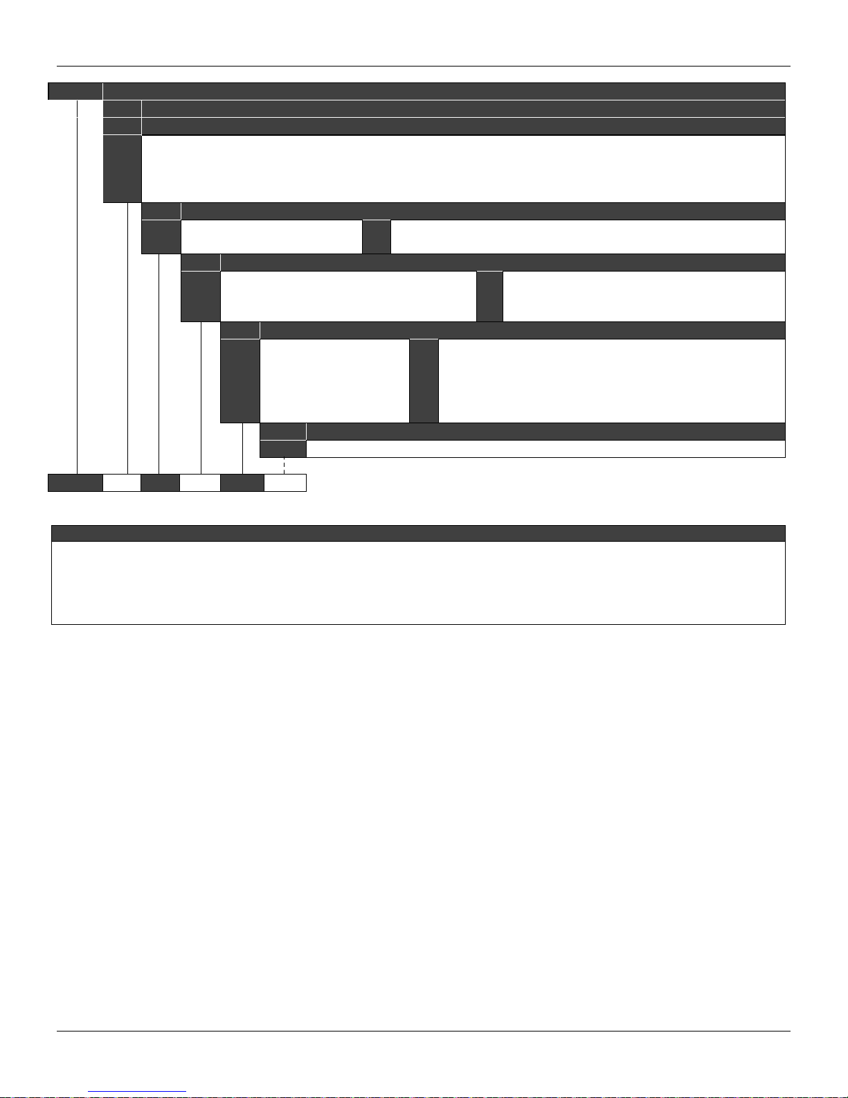
LD291 - Operation and Maintenance Instruction Manual
Optional Items
(1) Meets NACE MR – 01 – 75/ISO 15156 recommendations.
209-0241
209-0241
*Leave blank for no optional items.
SPARE PART NUMBER FOR SANITARY PRESSURE SENSOR
CODE Type Range Limits Range Limits
Min. Max. Unit Min. Max. Unit
Sanitary 12.5 500 mbar 5.02 201.09 inH
2
Sanitary 62.5 2500 mbar 25.13 1005,45 inH
3
Sanitary 0.625 25 bar 157.1 10054.5 inH
4
Sanitary 6.25 55.15 bar 90.65 799.89 psi
5
CODE Diaphragm Material
2
Hastelloy C276
H
316L SST
I
Monel
M
Tantalum
T
CODE Fill Fluid (Low Side)
Silicone DC-704 Oil
D
Inert Fluorolube MO-10 Oil (1) (4)
F
Inert Krytox Oil (1) (4)
K
CODE Process Connections
Thread IDF - 2” 300#
B
Thread RJT - 2” 300#
C
Tri-Clamp - 2” 300#
D
Thread SMS - 2” 300#
E
Tri-Clamp - 1 1/2” 300#
F
(2)
CODE
I N D * ← Typical Model Number
NOTES
Propileno Glicol Neobee M20 Oil (Approved 3A) (3)
N
Silicone DC-200/20 Oil
S
Syltherm 800 Oil
T
DN40 300# - DIN 11851
H
Tri-Clamp - 2” 800#
P
Tri-Clamp - 1 1/2” 800#
Q
User’s specifications
Z
O
2
O
2
O
2
(2)
(2) Silicone Oil is not recommended for Oxygen (O2) or Chlorine service.
(3) Compliant with 3A-7403 standard for food and other applications where sanitary connections are required:
- Neobee M2O Fill Fluid
- Finishing wet Face: 0,8 µm Ra (32 µ" AA)
- Wet O-Ring: Viton, Buna-N and Teflon
(4) Inert Fluid: Oxygen Compatibility, safe for oxygen service.
5.10

L5
e range can be extended up to 0.75
LRL and 1.2 URL with small degradation of
accuracy. The upper range value must be
2
Z
COD.
2
Z
COD.
4
(3)
Z
User´s specifications
COD.
Fill Fluid (Process Connection)
K
Krytox Oil
Z
User´s specifications
COD.
Lower Housing Material
COD.
Gasket Material
G
Grafoil (Flaxible Lead)
209-0241
L2 1 1 6 0 1 S 1 0
NOTES
(5) Inert Fluid: Safe for oxygen service.
209-0241 SPARE PART NUMBER FOR FLANGED PRESSURE SENSOR
COD.
L2
L3
L4
Type
Level
Level
Level
Level
COD.
Diaphragm Material (Sensor) and Fill Fluid (Sensor)
1 316L SST - Silicone Oil
COD.
Range Limits
Min. Max.
-50
-250
-2500
-25000
Process Connection
U
1” 150# (ANSI B16.5)
1” 300# (ANSI B16.5)
V
1” 600# (ANSI B16.5)
W
1½” 150# (ANSI B16.5)
O
1½” 300# (ANSI B16.5)
P
1½” 600# (ANSI B16.5)
Q
2” 150# (ANSI B16.5)
9
2” 300# (ANSI B16.5)
A
2” 600# (ANSI B16.5)
B
3" 150 # (ANSI B16.5)
1
3” 300# (ANSI B16.5)
Type and Material Flange
COD.
4
304 SST (slip-on flange)
5
316 SST (slip-on flange)
0
1
Min. Span Unit
50
250
2500
25000
Extension Lenght
0 mm (0”)
50 mm (2”)
100 mm (4”)
1
2
3
1,25
2,08
20,83
208,30
Diaphragm Material/Extension (Process Connection)
316 L SST / 316 SST
Hastelloy C276 / 316 SST
Monel 400 / 316 SST
Tantalum / 316 SST
kPa
kPa
kPa
kPa
Range Limits
Min. Max.
-200
-360
-3625
Carbon Steel (slip-on flange)
6
User´s specifications
Z
3
4
Min. Span Unit
-36
150 mm (6”)
200 mm (8”)
User´s specifications
200
36
360
3625
C
3” 600# (ANSI B16.5)
4” 150# (ANSI B16.5)
3
4” 300# (ANSI B16.5)
4
4” 600# (ANSI B16.5)
D
DN25 PN 10/40
5
DN40 PN 10/10
R
DN50 PN10/40
E
DN80 PN25/40
6
DN100 PN10/16
7
DN100 PN25/40
8
User´s specifications
5
6
L
5
0,3
3
30,2
Titanium / 316 SST (3)
Note: Th
inH2O
psi
psi
limited to the flange rating.
psi
316L SST with Teflon Lining
316L SST with Halar Lining
Maintenance Procedure
S
Silicone DC-200/20 Oil
Inert Fluorolube MO-10 Oil (4)
F
D
Silicone DC-704 Oil
0
Without Lower Housing
1
316L SST
Hastelloy C276
2
Super Duplex (UNS 32750)
3
0
Without Gasket
Copper
C
4
Duplex (UNS 31803)
304L SST
5
User´s specifications
Z
(1) Silicone Oils not recommendations for Oxygen (O2) or Chlorine service.
(2) Not applicable for vacuum service.
(3) Attention, check corrosion r ate for the proc es s , tantalum plate 0.1 mm, AISI 316L extension 3 to 6mm.
(4) Fluorolube fill fluid is not available for Monel diaphragm.
TYPICAL MODEL NUMBER
H
Halocarbon 4.2 Oil
Propileno Glicol (Neobee) Oil
N
Syltherm 800 Oil
T
Teflon (PTFE)
T
User´s specifications
Z
5.11

LD291 - Operation and Maintenance Instruction Manual
5.12

Section 6
O
A
D [Ohm
Process Fluid
Output Signal and
Protocol Communication
Power Supply
Load Limitation
Indicator
Hazardous Area
Certifications
European Directive
Information
Temperature Limits
Turn-on Time
TECHNICAL CHARACTERISTICS
Functional Specifications
Liquid, gas or steam.
Two-wire, 4-20 mA controlled according to NAMUR NE43 Specification and with superimposed digital
communication (HART Protocol). See the figure below.
12 to 45 Vdc.
1650
1500
]
1000
L
500
250
0
Optional 4½-digit numerical and 5-character alphanumerical LCD indicator.
Intrinsic Safe (FM, CSA, NEMKO, DEKRA/EXAM, CEPEL and NEPSI), non-incendive (FM, CSA and
CEPEL), explosion proof (FM, NEMKO and CEPEL) and dust ignition proof (FM).
Authorized representative in European Community
Smar Gmbh-Rheingaustrasse 9-55545 Bad Kreuzanach
PED Directive (97/23/EC) – Pressure Equipment Directive
This product is in compliance with the directive and it was designed and manufactured in accordance with
sound engineering practice using several standards from ANSI, ASTM, DIN and JIS.
EMC Directive (2004/108/EC) - Eletromagnetic Compatibility
The EMC test was performed according to IEC standard: IEC61326-1:2006, IEC61326-2-3:2006,
IEC61000-6-4:2006, IEC61000-6-2:2005. For use in environment only.
Keep the shield insulated at the instrument side, connecting the other one to the ground if necessary to
use shielded cable.
ATEX Directive (94/9/EC) – Equipment and protective systems intended for use in potentially
explosive atmospheres.
This product was certified according European Standards at NEMKO and EXAM (old DMT). The certified
body for manufacturing quality assessment is EXAM (number 0158).
LVD Directive 2006/95/EC – Electrical Equipment designed for use within certain voltage limits
According the LVD directive Annex II the equipment under ATEX “Electrical equipment for use in an
explosive atmosphere” directive are excluded from scope from this directive.
The EC declarations of conformity for all applicable European directives for this product can be found
at www.smar.com
.
Ambient
-40 to 85 ºC -40 to 185 ºF
-15 to 85 ºC -59 to 185 ºF
-40
0 to 85 ºC 32 to 185 ºF Fluorolube Oil
Process
-25 to 85 ºC -13 to 185 ºF Viton ‘Ring
-40
-15
Storage
Digital
Display
40
-20 to 80 ºC -4 to 176 ºF Operation
-40
Performs within specifications in less than 5 seconds after power is applied to the transmitter.
OPERATING AREA
12
to
100 ºC -40
to
150 ºC -40
to
150 ºC -59
to
100 ºC -40
to
85 ºC -40
20
POWER SUPPLY [Volt]
Temperature Limits
to
to
to
to
to
4-20mA AND
DIGITAL COMMUNICATION
4-20mA only
30
40 45
LD290I
212 ºF Silicone Oil
302 ºF
302 ºF
LD290L
LD290I
212 ºF
185 ºF without damage
6.1

LD291 - Operation Maintenance Instruction Manual
3
Zero and Span
Adjustments
Failure Alarm
Volumetric
By configurator or local adjustment from 0 to 0.975 URL, URL = Upper Range Limit.
In case of sensor or circuit failure, the self-diagnostics drives the output to 3.6 or 21.0 mA, according to
the user's choice.
Less than 0.15 cm
(0.01 in3)
Displacement
14 MPa (2000 psi) for range 2,3 and 4.
31 MPa (4500 psi) for ranges 5.
For ANSI/DIN Level flanges (LD290L models):
Overpressure Limits
(MWP – Maximum
Working Pressure)
150 #: 6 psia to 235 psi (-0.6 to 16 bar) at 199.4 °F (93 °C)
300 #: 6 psia to 620 psi (-0.6 to 43 bar) at 199.4 °F (93 °C)
600 #: 6 psia to 1240 psi (-0.6 to 85 bar) at 199.4 °F (93 °C)
PN10/16: -60 kPa to 1.02 MPa at 212 °F (100 °C)
PN25/40: -60 kPa to 2.55 MPa at 212 °F (100 °C)
These overpressures will not damage the transmitter, but a new calibration may be necessary.
Damping Adjustment
Humidity Limits
0 to 128 seconds in addition to intrinsic sensor response time (0.2 s) (via digital communication).
0 to 100% RH.
Can be done through digital communication using the Hart Protocol or, partially, through local adjustment.
Configurator
Configuration
CONF 401
It works in the windows platform (95, 98, 2000, XP and NT).
For equipment updates and HPC301 software, just check: www.smarreasearch.com
Palm
See Palm Handbook.
Performance Specifications
Reference Conditions
Accuracy
Stability
Temperature Effect
Power Supply Effect
Mounting Position Effect
Electromagnetic
Interference Effect
Range starting at zero, temperature 25
fill fluid, isolating diaphragms in 316L SS and digital trim equal to lower and upper range values.
For ranges 2, 3, 4 and 5:
±0.075% of span (for span >= 0.1 URL)
±[0.0375 + 0.00375 URL/SPAN] % of span (for span < 0.1 URL)
For Level Transmitter:
± 0.08 % of span (for span ≥ 0.1 URL)
± [0.0504 + 0.0047 URL/span] % of span (for span < 0.1 URL)
For Insertion Transmitter:
±0.2% of span
0.15% of URL for 5 years
± [0.02 URL + 0.06% of span], per 20 ºC (68 ºF) for span >= 0.2 URL
± [0.023 URL+0.045% of span], per 20ºC (68 ºF) for span < 0.2 URL
For Level Transmitter:
6 mmH
17 mmH
O per 20ºC for 4” and DN100.
2
O per 20ºC for 3” and DN80.
2
0.005% of calibrated span per volt.
Zero shift of up to 250 Pa (1 inH
Designed to comply with, Approved according to IEC61326-1:2006, IEC61326-2-3:2006, IEC61000-64:2006, IEC61000-6-2:2005.
Physical Specifications
Electrical Connection
Process Connection
Wetted Parts
Nonwetted Parts
See options in ordering code.
See options in ordering code.
316L SST and Hastelloy C276.
Diaphragm for sanitary models available in Monel 400 and Tantalum.
Electronic Housing
Injected aluminum with polyester painting or 316 SST. According to NEMA Type 4X or Type 4, IP66,
IP66W*.
*The IP66W sealing test (immersion) was performed at 1 bar for 24 hours. For any other situation, please consult Smar. IP66W
tested for 200h to according NBR 8094 / ASTM B 117 standard.
o
C (77 oF), atmospheric pressure, power supply of 24 Vdc, silicone oil
O), which can be calibrated out. No span effect.
2
6.2

Nonwetted Parts
Technical Characteristic
Level Flange (LD290L)
316L SST, 304 SST and Plated Carbon Steel.
Fill Fluid
Silicone or Fluorolube Oil.
Cover O-Rings
Buna N.
Mounting Bracket
Optional universal mounting bracket for surface or vertical/horizontal 2”-pipe (DN 50) carbon steel with
polyester painting or 316 SST. Accessories (bolts, nuts, washers and U-clamp) in carbon steel or 316
SST.
Identification Plate
316 SST.
Approximate Weights
< 2.0kg (4 lb):aluminum.housing bracket.
6.3

LD291 - Operation Maintenance Instruction Manual
Ordering Code
MODEL GAGE PRESSURE TRANSMITTERS
LD291M
LD291M 2 1 I 1 1 A 0 *
4-20 mA + HART®
CODE Type Range Limits Range Limits
* Leave blank for no optional items.
Min. Max. Unit Min. Max. Unit
Gage 12.5 500 mbar 5.02 201.09 inH
2
Gage 62.5 2500 mbar 25.13 1005.45 inH
3
Gage 0.625 25 bar 157.1 10054.5 inH
4
Gage 6.25 250 bar 90.65 3625.94 psi
5
CODE Diaphragm Material and Fill Fluid
316L SST - Silicone Oil
1
316L SST – Inert Fluorolube Oil (2)
2
Hastelloy C276 - Silicone Oil (1)
3
Hastelloy C276 – Inert Fluorolube Oil (2)
4
316L SST – Inert Krytox Oil (2)
D
Hastelloy C276 – Inert Krytox Oil (2)
E
316L SST – Inert Halocarbon 4.2 Oil (2)
Q
Hastelloy C276 – Inert Halocarbon 4.2 Oil (2)
R
CODE Process Connections Material
H
Hastelloy C276 (1)
316L SST
I
User’s specifications
Z
CODE Local Indicator
Without Indicator
0
CODE Process Connections
1/2 - 14 NPT - Female
1
M20 X 1,5 Male
A
G 1/2 A DIN 16288 - Form B
G
G 1/2 DIN 16288 - Form D
H
1/2 - 14 NPT - Male
M
CODE Electrical Connections
1/2 - 14 NPT (3)
0
1/2 - 14 NPT X 3/4 NPT (316 SST) - with adapter (4)
1
2
1/2 - 14 NPT X 3/4 BSP (316 SST) - with adapter (6)
3
1/2 - 14 NPT X 1/2 BSP (316 SST) - with adapter (6)
1/2 - 1/2 NPTF (316 SST) - with adapter
4
1/2 - 3/4 NPTF (316 SST) - with adapter
5
CODE Mounting Bracket
Without Mounting Bracket
0
Carbon Steel Mounting Bracket with Carbon Steel accessories
1
316 SST Mounting Bracket with 316 SST accessories
2
Carbon Steel Mounting Bracket with 316 SST accessories
7
Flat; 304 SST Mounting Bracket with 316SST accessories
A
CODE Optional Items
O
2
O
2
O
2
With Indicator
1
1/2 BSP – Male
U
Valve Manifold integrated to the transmitter
V
1" NPT Sealed
X
User’s specifications
Z
TYPICAL MODEL NUMBER
A
M20 X 1.5 (5)
B
PG 13.5 DIN (5)
User’s specifications
Z
6.4

MODEL GAGE PRESSURE TRANSMITTER (CONTINUATION)
CODE Output Signal
LD291M G0 H0 I1 P0 Y0 Y5 J0 ← TYPICAL MODEL NUMBER
4-20 mA
G0
CODE Housing Material (9) (10)
Aluminium (IP/TYPE)
H0
316 SST (IP/TYPE)
H1
Aluminium for Saline Atmosphere (IPW/TYPEX) (8)
H2
CODE Identification Plate
FM: XP, IS, NI, DI
I1
NEMKO: Ex-d, Ex-ia
I2
CSA: XP, IS, NI, DI
I3
CODE Painting
Munsell N 6,5 Gray
P0
Polyester Black
P3
Epoxy White
P4
CODE Display Unit 1
Percentage
Y0
Current (mA)
Y1
Pressure (Eng. Unit)
Y2
CODE Display Unit 2
Y0
Y4
Y5
EXAM (DMT): Ex-ia; NEMKO: Ex-d
I4
CEPEL: Ex-d, Ex-ia
I5
Without Certification
I6
Percentage
Current (mA)
Pressure (Eng. Unit)
CODE Tag Plate
With TAG
J0
Without TAG
J1
H3
316 SST for Saline Atmosphere (IPW/TYPEX) (8)
H4
Copper Free Aluminium for Saline Atmosphere (IPW/TYPEX) (8)
Polyester Yellow
P5
Without Painting
P8
Blue Safety Base Epoxy –Eletrostatic Painting
P9
Y3
YU
Optional Items
Special Procedures C1 –Degrease Cleaning (Oxygen or Chlorine Service)
Burnout
Características Especiais ZZ – User Specification
NOTES
(1) Meets NACE material recommendation per MR-01-75.
(2) Inert fluid: safe for oxygen service.
(3)Certificate for use in Hazardous Locations (CEPEL, NEPSI, NEMKO, EXAM, FM, CSA).
(4) Certificate for use in Hazardous Locations (CEPEL, CSA).
(5) Certificate for use in Hazardous Locations (CEPEL, NEPSI, NEMKO, EXAM).
(6) Not certified for use in hazardous locations.
(7) Limited values to 4 1/2 digits; limited unit to 5 characters.
(8) IPW/TYPEX was tested for 200 hours according to NBR 8094 / ASTM B 117 standard.
(9) IPX8 tested for 10 meters of water column for 24 hours.
(10) Ingress Protection:
Products CEPEL NEMKO/EXAM FM CSA NEPSI
LD29X IP66/W IP66/68/W Type 4X/6/6P Type 4X IP67
BD – Down Scale
BU – Up Scale
EXAM (DMT) Grupo I, M1 Ex-ia
I7
NEPSI: Ex-ia, Ex-d
ID
NEMKO: Ex-d
IJ
Temperature (Temperature)Y
User’s specification (7)U
Temperature (Temperature)Y
Y6
YU
User’s specification (7)U
User’s specification
J2
Technical Characteristic
6.5

LD291 - Operation Maintenance Instruction Manual
MODEL SANITARY PRESSURE TRANSMITTERS
LD291S
LD291S 2 I N 1 D 0 V 1 2 I D * ← Typical Model Number
*Leave blank for no optional items.
4-20 mA + HART®
CODE Type Range Limits Range Limits
Min. Max. Unit Min. Max. Unit
Sanitary 12.5 500 mbar 5.02 201.09 inH
2
Sanitary 62.5 2500 mbar 25.13 1005,45 inH
3
Sanitary 0.625 25 bar 157.1 10054.5 inH
4
Sanitary 6.25 55.15 bar 90.65 799.89 psi
5
CODE Diaphragm Material
316L SST
I
CODE Fill Fluid
Silicone DC-200/20 Oil
S
CODE Local Indicator
Without Indicator
0
With Indicator
1
CODE Process Connections
Thread IDF - 2” 300# (2)
B
Thread RJT - 2” 300#
C
Tri-Clamp - 2” 300# (2)
D
Thread SMS - 2” 300# (2)
E
Tri-Clamp - 1 1/2” 300# (2)
F
CODE Electrical Connections
0
1/2 - 14 NPT (3)
1
1/2 - 14 NPT X 3/4 NPT (316 SST) - with adapter (4)
2
1/2 - 14 NPT X 3/4 BSP (316 SST) - with adapter (9)
3
1/2 - 14 NPT X 1/2 BSP (316 SST) - with adapter (9)
1/2 - 1/2 NPTF (316 SST) - with adapter
4
1/2 - 3/4 NPTF (316 SST) - with adapter
5
CODE O’Ring Material
Without O’Ring
0
Buna-N (2)
B
Teflon (2)
T
H
P
Q
Z
CODE Adaptation Sleeve
Without Sleeve
0
With Adaptation Sleeve in 316 SST
1
Tri-Clamp Connection
CODE
Without Clamp
0
With Tri-Clamp in 304 SST
2
CODE
H
I
O
2
O
2
O
2
DN40 300# - DIN 11851
Tri-Clamp - 2” 800# (2)
Tri-Clamp - 1 1/2” 800# (2)
User’s specifications
A
M20 X 1.5 (5)
B
PG 13.5 DIN (5)
User’s specifications
Z
V
Viton (2)
User´s specifications
Z
Diaphragm Material (Sanitary Connection)
Hastelloy C276
316L SST
CODE Fill Fluid (Sanitary Connection)
Silicone DC-704 Oil
D
Fluorolube MO-10 Oil (1)
F
Propilene Glicol (Neobee) Oil (2)
N
Silicone DC-200/20 Oil
S
Syltherm 800 Oil
T
User’s specifications
Z
Optional Items
CODE
6.6

MODEL SANITARY PRESSURE TRANSMITTERS (CONTINUATION)
LD291S G0 H0 I1 P0 Y0 Y5 J0* ← TYPICAL MODEL NUMBER
COD. Output Signal
4-20 mA
G0
COD. Housing Material (7) (8)
Aluminium (IP/TYPE)
H0
316 SST (IP/TYPE)
H1
COD. Identification Plate
I1
I2
I3
FM: XP, IS, NI, DI
NEMKO: Ex-d, Ex-ia
CSA: XP, IS, NI, DI
COD. Painting
Munsell N 6,5 Gray
P0
Polyester Black
P3
Epoxy White
P4
COD. Display Unit 1
Percentage
Y0
Current (mA)
Y1
Pressure (Eng. Unit)
Y2
COD. Display Unit 2
Y0
Y4
Y5
EXAM (DMT): Ex-ia; NEMKO: Ex-d
I4
CEPEL: Ex-d, Ex-ia
I5
Without Certification
I6
Percentage
Current (mA)
Pressure (Eng. Unit)
COD. Tag Plate
With TAG
J0
Without TAG
J1
Polyester Yellow
P5
Epoxy Yellow
P6
Y3
YU
Temperature (Temperature)Y
User’s specification (6)U
Temperature (Temperature)Y
Y6
YU
User’s specification (6)U
User’s specification
J2
Optional Items
Special Procedures
Burnout
NOTE
(1) Inert Fluid: safe for oxygen service.
(2) Compliant with 3A-7403 standard for food and other applications where sanitary connections are required.
- Neobee M2O Fill Fluid
- Finishing wet Face: 0.8 µm Ra (32 µ" AA)
- Wet O-Ring: Viton, Teflon and Buna-N
(3)Certificate for use in Hazardous Locations (CEPEL, NEPSI, NEMKO, EXAM, FM, CSA).
(4) Certificate for use in Hazardous Locations (CEPEL, CSA).
(5) Certificate for use in Hazardous Locations (CEPEL, NEPSI, NEMKO, EXAM).
(6) Limited values to 4 1/2 digits; limited unit to 5 characters.
(7) IPX8 tested for 10 meters of water column for 24 hours.
(8) Ingress Protection:
Produtos CEPEL NEMKO/EXAM FM CSA NEPSI
LD29X IP66/W IP66/68/W Type 4X/6/6P Type 4X IP67
(9) Not certified for use in hazardous locations.
C1 –Degrease Cleaning (Oxygen or Chlorine Service)
C4 - Polishing of the sanitary connections according to 3A Certification (2)
BD – Down Scale
BU – Up Scale
Technical Characteristic
6.7

LD291 - Operation Maintenance Instruction Manual
®
MODEL LOW COST FLANGED PRESSURE TRANSMITTER
LD291L
4-20 mA + HART
COD.
Type
2
Level 12.5 500 mbar 5.02 201.09 inH
3
Level 62.5 2500 mbar 25.13 1005.45 inH
4
Level 0.625 25 bar 157.1 10054.5 inH
5
Level 6.25 250 bar 90.65 3625.94 psi
COD.
LD291L 2 1 1 1 0 6 2 1 S 1 T *
*Leave it blank when there are not optional items.
Range Limits
Min. Max.
Unit
Diaphragm Material (Sensor) and Fill Fluid (Sensor)
316L SST - Silicone Oil
1
Local Indicator
COD.
Without Indicator
0
COD.
Process Connection
1” 150# (ANSI B16.5)
U
1” 300# (ANSI B16.5)
V
1” 600# (ANSI B16.5)
W
1½” 150# (ANSI B16.5)
O
1½” 300# (ANSI B16.5)
P
1½” 600# (ANSI B16.5)
Q
2” 150# (ANSI B16.5)
9
2” 300# (ANSI B16.5)
A
2” 600# (ANSI B16.5)
B
3" 150 # (ANSI B16.5)
1
3” 300# (ANSI B16.5)
2
Electrical Connection
COD.
1/2 - 14 NPT (3)
0
1/2 - 14 NPT X 3/4 NPT (AI 316) - with adapter (4)
1
1/2 - 14 NPT X 3/4 BSP (AI 316) - with adapter (13)
2
1/2 - 14 NPT X 1/2 BSP (AI 316) - with adapter (13)
3
1/2 - 1/2 NPTF (AI 316) - with adapter
4
Type and Material Flange
COD.
4
304 SST (slip-on flange)
316 SST (slip-on flange)
5
Extension Lenght
COD.
0 mm (0”)
0
50 mm (2”)
1
Diaphragm Material / Extension (Process Connection)
COD.
1
316 L SST / 316 SST
Hastelloy C276 / 316 SST
2
Monel 400 / 316 SST
3
Tantalum / 316 SST (6)
4
Range Limits
Min. Max.
With Digital Indicator
1
C
D
R
E
Carbon Steel (slip-on flange)
6
User´s specifications
Z
100 mm (4”)
2
150 mm (6”)
3
COD. Fill Fluid (Process Connection)
S
Silicone DC-200/20 Oil
F
Inert Fluorolube MO-10 Oil (7)
Silicone DC-704 Oil
D
Krytox Oil
K
COD. Lower Housing Material
0
Without Lower Housing
1
316L SST
Hastelloy C276
2
Super Duplex (UNS 32750)
3
COD. Gasket Material
0
Without Gasket
Copper
C
Grafoil (Flexible Lead)
G
CODE Optional Items
Unit
O
2
O
2
O
2
3” 600# (ANSI B16.5)
4” 150# (ANSI B16.5)
3
4” 300# (ANSI B16.5)
4
4” 600# (ANSI B16.5)
DN25 PN 10/40
5
DN40 PN 10/10
DN50 PN10/40
DN80 PN25/40
6
DN100 PN10/16
7
DN100 PN25/40
8
User´s specifications
Z
1/2 - 3/4 NPTF (AI 316) - with adapter
5
M20 X 1.5 (5)
A
PG 13.5 DIN (5)
B
User´s specifications
Z
Titanium / 316 SST (6)
5
316L SST with Teflon Lining
6
316L SST with Halar Lining
L
User´s specifications
Z
H
N
T
Z
TYPICAL MODEL NUMBER
200 mm (8”)
4
User´s specifications
Z
Halocarbon 4.2 Oil
Propileno Glicol (Neobee) Oil
Syltherm 800 Oil
User´s specifications
Duplex (UNS 31803)
4
304L SST
5
User´s specifications
Z
316L SST
I
Teflon (PTFE)
T
User´s specifications
Z
6.8

MODEL LOW COST FLANGED PRESSURE TRANSMITTER (CONTINUATION)
LD291L G0 H0 I1 P0 Y0 Y5 J0 ← TYPICAL MODEL NUMBER
COD. Output Signal
4-20 mA
G0
COD. Housing Material (11) (12)
Aluminium (IP/TYPE)
H0
316 SST (IP/TYPE)
H1
Aluminium for saline atmosphere (IPW/TYPEX) (10)
H2
COD. Identification Plate
I1
I2
I3
FM: XP, IS, NI, DI
NEMKO: Ex-d, Ex-ia
CSA: XP, IS, NI, DI
COD. Painting
Munsell N 6,5 Gray
P0
Polyester Black
P3
Epoxy White
P4
Polyester Yellow
P5
COD. Display Unit 1
Percentage
Y0
Current (mA)
Y1
Pressure (Eng. Unit)
Y2
COD. Display Unit 2
Y0
Y4
Y5
EXAM (DMT): Ex-ia; NEMKO: Ex-d
I4
CEPEL: Ex-d, Ex-ia
I5
Without Certification
I6
Percentage
Current (mA)
Pressure (Eng. Unit)
COD. Tag Plate
With TAG
J0
Without TAG
J1
H3
316 SST for saline atmosphere (IPW/TYPEX) (10)
H4
Copper Free Aluminium for Saline Atmosphere (IPW/TYPEX) (10)
Epoxy Yellow
P6
Without Painting
P8
Blue Safety Base Epoxy – Eletrostatic Painting
P9
Safety Base Polyester – Eletrostatic Painting
PC
Temperature (Temperature)Y
Y3
YU
User’s specification (9)U
Temperature (Temperature)Y
Y6
YU
User’s specification (9)U
J2
Optional Items
Special Procedures C1 –Degrease Cleaning (Oxygen or Chlorine Service)
Burnout
Lower Housing
Connection
NOTES
(1) Silicone Oils not recommendations for Oxygen (O2) or Chlorine service.
(2) Not applicable for vacuum service.
(3) Certificate for use in Hazardous Locations (CEPEL, NEPSI, NEMKO, EXAM, FM, CSA).
(4) Certificate for use in Hazardous Locations (CEPEL, CSA).
(5) Certificate for use in Hazardous Locations (CEPEL, NEPSI, NEMKO, EXAM).
(6) Attention, check corrosion rate for the process, tantalum plate 0.1 mm, AISI 316L extension 3 to 6mm.
(7) Fluorolube fill fluid is not available for Monel diaphragm.
(8) Inert Fluid: Safe for oxygen service.
(9) Limited values to 4 1/2 digits; limited unit to 5 characters.
(10) IPW/TYPEX was tested for 200 hours according to NBR 8094 / ASTM B 117 standard.
(11) IPX8 tested for 10 meters of water column for 24 hours.
(12) Ingress Protection:
(13) Not certified for use in hazardous locations.
Products CEPEL NEMKO/EXAM FM CSA NEPSI
LD29X IP66/W IP66/68/W Type 4X/6/6P Type 4X IP67
BD – Down Scale
BU – Up Scale
U0 – With 1 Flush Connection 1/4” NPT (if supplied with lower housing)
U1 – With 2 Flush Connections 1/4” NPT per 180º
U2 – With 2 Flush Connections 1/4” NPT per 90º
U3 – With 2 Flush Connections 1/2” - 14 NPT per 180º (with cover)
U4 – Without Flush Connection
EXAM (DMT) Grupo I, M1 Ex-ia
I7
NEMKO: Ex-d
IJ
User’s specification
Technical Characteristic
6.9

LD291 - Operation Maintenance Instruction Manual
MODEL PRESSURE TRANSMITTER WITH EXTENDED PROBE
4-20 mA + HART
LD291I
COD. Type Range Limits
2
LD291I 2 1 1 3 A I 1 N * ← TYPICAL MODEL
*Leave blank for no optional items.
®
Min. Max. Unit
Level 12.5 500 mbar
COD. Diaphragm Material and Fill Fluid
1 316L SST – Silicon Oil (1)
COD. Local Indicator
Without Indicator
0
With Indicator
1
COD. Fixing Transmitter
Bracket in L
1
Flanged Bracket
2
Triclamp 3” (10)
3
COD. Electrical Connection
0
1/2 - 14 NPT (2)
1
1/2 - 14 NPT X 3/4 NPT (316 SST) – with adapter (3)
2
1/2 - 14 NPT X 3/4 BSP (316 SST) - with adapter (5)
3
1/2 - 14 NPT X 1/2 BSP (316 SST) - with adapter (5)
1/2 - 1/2 NPTF (316 SST) - with adapter
4
1/2 - 3/4 NPTF (316 SST) - with adapter
5
COD. Probe Material/Diaphragm (Wetted Parts)
304L SST / 316L SST
A
316L SST / 316L SST
I
316L SST / Hastelloy C276
U
User’s specification
Z
COD. Probe Length
500 mm
1
630 mm
2
800 mm
3
1000 mm
4
1250 mm
5
COD. Probe Fill Fluid
N
Z
User’s specification
Z
Propileno Glicol Oil (Neobee M20) (10)
User’s specification
COD. Optional Items
A
M20 X 1.5 (4)
B
PG 13.5 DIN (4)
User’s specification
Z
6
7
8
9
Z
1600 mm
2000 mm
2500 mm
3200 mm
User’s specification
6.10

MODEL PRESSURE TRANSMITTER WITH EXTENDED PROBE (CONTINUATION)
LD291I G0 H0 IN P0 Y0 Y5 J0 * ← TYPICAL MODEL NUMBER
COD. Output Signal
4-20 mA
G0
0-20 mA
G1
COD. Housing Material (8) (9)
Aluminium (IP/TYPE)
H0
316 SST (IP/TYPE)
H1
Aluminium for saline atmosphere (IPW/TYPEX) (7)
H2
COD. Identification Plate
IN
CEPEL: Ex-ia
COD. Painting
Munsell N 6,5 Gray
P0
Polyester Black
P3
Epoxy White
P4
Polyester Yellow
P5
COD. Display Unit 1
Percentage
Y0
Current (mA)
Y1
Pressure (Eng. Unit)
Y2
COD. Display Unit 2
Y0
Y4
Y5
10-50 mA
G2
Percentage
Current (mA)
Pressure (Eng. Unit)
COD. Tag Plate
With TAG
J0
Without TAG
J1
H3
316 SST for saline atmosphere (IPW/TYPEX) (7)
H4
Copper Free Aluminium for Saline Atmosphere (IPW/TYPEX) (7)
Epoxy Yellow
P6
Without Painting
P8
Blue Safety Base Epoxy – Eletrostatic Painting
P9
Safety Base Polyester – Eletrostatic Painting
PC
Temperature (Temperature)Y
Y3
YU
User Specification (6)U
Temperature (Temperature)Y
Y6
YU
User Specification (6)U
User Specification
J2
Optional Items
Special Procedures C1 –Degrease Cleaning (Oxygen or Chlorine Service)
C4 - Polishing of the sanitary connections according to 3A Certification (10)
Burnout BD – Down Scale
BU – Up Scale
Special Characteristics ZZ – User’s specifications
NOTES
(1) Silicone Oils not recommendations for Oxygen (O2) or Chlorine service.
(2) Certificate for use in Hazardous Locations (CEPEL, NEPSI, NEMKO, EXAM, FM, CSA).
(3) Certificate for use in Hazardous Locations (CEPEL, CSA).
(4) Certificate for use in Hazardous Locations (CEPEL, NEPSI, NEMKO, EXAM).
(5) Not certified for use in hazardous locations.
(6) Limited values to 4 1/2 digits; limited unit to 5 characters.
(7) IPW/TYPEX was tested for 200 hours according to NBR 8094 / ASTM B 117 standard.
(8) IPX8 tested for 10 meters of water column for 24 hours.
(9) Ingress Protection:
(10) Compliant with 3A-7403 standard for food and other applications where sanitary connections are required.
- Neobee M2O Fill Fluid
- Finishing wet Face: 0.8 µm Ra (32 µ" AA)
- Wet O-Ring: Viton, Teflon and Buna-N
Products CEPEL NEMKO/EXAM FM CSA NEPSI
LD29X IP66/W IP66/68/W Type 4X/6/6P Type 4X IP67
Technical Characteristic
6.11

LD291 - Operation Maintenance Instruction Manual
6.12

Appendix A
NOTE
The IP68 sealing test (immersion) was performed at 1 bar for 24 hours. For any other situation,
please consult Smar.
CERTIFICATIONS INFORMATIONS
European Directi ve Information
Other Aprovals
Hazardous Locations Certifications
Authorized representative in European Community
Smar Gmbh-Rheingaustrasse 9-55545 Bad Kreuzanach
PED Directive (97/23/EC) – Pressure Equipment Directive
This product is in compliance with the directive and it was designed and manufactured in
accordance with sound engineering practice using several standards from ANSI, ASTM, DIN and
JIS.
EMC Directive (2004/108/EC) - Eletromagnetic Compatibility
The EMC test was performed according to IEC standard: IEC61326-1:2006, IEC61326-2-3:2006,
IEC61000-6-4:2006, IEC61000-6-2:2005. For use in environment only.
Keep the shield insulated at the instrument side, connecting the other one to the ground if
necessary to use shielded cable.
ATEX Directive (94/9/EC) – Equipment and protective systems intended for use in potentially
explosive atmospheres.
This product was certified according European Standards at NEMKO and EXAM (old DMT). The
certified body for manufacturing quality assessment is EXAM (number 0158).
LVD Directive 2006/95/EC – Electrical Equipment designed for use within certain voltage
limits
According the LVD directive Annex II the equipment under ATEX “Electrical equipment for use in an
explosive atmosphere” directive are excluded from scope from this directive.
The EC declarations of conformity for all applicable European directives for this product can be
found at www.smar.com.
FMEDA Report
Certifier Body: Exida
Failure Modes, Effects and Diagnostics Analysis (Report No. R02 / 11-19).
North American Certifications
FM Approvals
Certificate N: FM 4B9A4.AX
Explosion-proof for Clas s I, Division 1, Groups A, B, C, and D;
Dust-ignition proof for Class II, Division 1, Groups E, F, and G; Class III, Division 1; hazardous
locations.
Intrinsically Safe for use in Cl ass I, Division 1, Groups A, B, C, and D; Class II, Division 1, Groups E,
F, and G; Class III, Division 1;
Non-incendive for Class I, Division 2, Groups A, B, C, and D
Entity parameters: V
= 30 Vdc I
max
Ambient Temperature: (-40ºC < T
Enclosure Type: 4X or Type 4.
CSA International (Canadian Standards Association)
Certificate N: CSA1111005
Class 2258 02 Hazardous Locations for Clas s I, Division 1, Groups B, C and D; Class II, Division 1,
Groups E, F and G; Class III, Division 1; Class I, Division 2, Groups A, B, C and D; Class II, Division
2, Groups E, F and G; Class III.
= 110 mA Ci = 8nF Li = 0.24 mH
max
amb <+60ºC).
A.1

LD291 - Certifications Information
Class 2258 03 Intrinsicall y Safe and Non-Incendive Systems for Class I, Division 1, Groups A, B, C
e D, Class II, Division 1, Groups E, F e G, Class III, Division 1. Intrinsically Safe when connected
through CSA Certified Di ode Safety Barrier, 28 V
Class 2258 04 Intrinsically Safe, Entity for Class I, Division 1, Groups A, B, C and D; Class II,
Division 1, Groups E, F and G; Class III, Division 1. Intrinsically safe with entity parameters: Vmax =
28 V, Imax = 100 mA, Ci = 5 nF, Li = 0 uH, when connected through CSA Certified Safety Barriers.
Ambient Temperature: (-20ºC < T
Enclosure Type: 4 or Type 4X.
European Certifications
Certificate No: Nemko 03 ATEX 133X
ATEX Intrinsically Safe Group II 1GD, Ex ia IIC T4
Entity Parameters: Pi = 0.7 W Ui = 28 V Ii = 100 mA Ci = 2 nF Li = Neg
Ambient Temperature: (-20 ºC < T
Certificate No: Nemko 02 ATEX 149X
ATEX Explosion Proof Group II 2G, Exd IIC T6
Enclosure Type: IP66/68 or IP66/68W
Special conditions for safe use:
Certificate No: DMT 01 ATEX E 059
ATEX Intrinsically Safe
Group II 1/2 G, Ex ia, IIC T4/T5/T6
Ambient Temperature: -40 ºC < T
Entity Parameters: Ui = 28 Vdc Ii = 93 mA Ci ≤ 5 nF Li = neg
South American Certifications
Certificado No: CEPEL-Ex-049/95
Intrinsicamente Seguro - Ex-ia IIC T5
• Parâmetros: Ui = 30 Vdc Ii = 100 mA Ci =6,4nF Li = neg Pi=0,7 W
Temperatura Ambiente: (-20 ºC < T
A.2
amb <+40ºC).
amb <+62 ºC).
max
, 300 Ω
min
.
1. The transmitters are marked with three options for the indication of the protection code. The
certification is valid only when the protection code is indicated in one of the boxes following the
code.
The following options apply:
• Ex d IIC T6 ( ) with X ticked in the parenthesis:
The Ex d IIC T6 protection according to certificate Nemko 02ATEX035X /
02ATEX149X applies for the specific transmitter. Certified Ex d IIC cables entries shall be
used.
• Ex ia IIC T4 ( ) with X ticked in the parenthesis:
The Ex ia IIC T4 protection according to certificate Nemko 03ATEX133X applies for the
specific transmitter. Certified diode safety barriers shall be used.
• Ex d IIC T6 / Ex ia IIC T4 ( ) with X ticked in the parenthesis:
The transmitter has double protection. Both Ex d IIC T6 and Ex ia IIC T4 protection
apply for the specific transmitter according to certificates Nemko 02ATEX035X/
02ATEX149X and Nemko 03ATEX133X. In this case the transmitter shall be fitted with
appropriate certified cable entries Ex d IIC and the electric circuit supplied by a certified
diode safety barrier as specified for the protection Ex ia IIC T4.
2. For enclosures of the transmitters made of aluminum impact and friction hazards shall be
considered when the transmitter is used in category II 1 G according to EN 50284 clause 4.3.1.
3. The diode safety barrier shall have a linear resistive output characteristic.
4. The pressure of the potentially explosive atmosphere surrounding the transmitter shall be
within the range 0.8 mbar to 1.1 mbar.
amb <+85 ºC
<+50 ºC).
amb

Certificado No: CEPEL-Ex-039/96
Á Prova de Explosão - Ex-d IIC T6
Temperatura Ambiente: (-20 ºC < T
Grau de proteção: IP66 ou IP66W.
Asian Certifications
Certificate No: Nepsi GYJ05602
Intrinsically safe - Ex ia, IIC T4/T5/T6
Ambient Temperature: -40 ºC < T
amb <+85 ºC
Entity Parameters: Ui = 28 Vdc Ii = 93 mA Ci ≤ 5 nF Li = neg
Certificate No: Nepsi GYJ05601
Explosion proof - Ex d IIC T6
Ambient Temperature: -20 ºC < T
amb
Identification Plate and Control Drawing
Identification Pla te
• Identification of Intrinsic ally Safe and Explosion Proof for gas and steam:
FM
<+40 ºC).
amb
<+40 ºC.
Appendix A
CSA
A.3

LD291 - Certifications Information
NEMKO and DMT
CEPEL
A.4

NEPSI
Appendix A
• Identification if Intrinsically Safe and Explosion Proof for saline atmospheres:
FM
CSA
NEMKO and DMT
A.5

LD291 - Certifications Information
CEPEL
A.6

Appendix A
NUMBER
SCALE
DRAWN CHECKED PROJECT APPROVAL
REV BY DOCAPPROVAL
SHEET
smar
EQUIPMENT:
APPROVAL CONTROLLED BY C.A.R.
LD290/LD291/LD301 - CONTROL DRA WING
FOR NON-INCENDIVE: CLASS I, DIV. 2
FOR INTRINSICALLY SAFE: CLASS I, DIV. 1
102A0435
01/01
NON HAZARDOUS OR DIVISION 2 AREA
SHIELDING
OPTIONAL
+
ENTITY PARAMETERS FOR ASSOCIATED APPARATUS
250
min
SIGNAL
R
BARRIER
GROUND BUS
ASSOCIATED APPARATUS
W
EARTH IN EXCESS OF 250VAC OR 250VDC.
SOURCE OF POTENTIAL IN RELATION TO
NORMAL OR ABNORMAL CONDITIONS, A
BE SUPPLIED FROM, NOR CONTAIN UNDER
UNSPECIFIED, EXCEPT THAT IT MUST NOT
SAFE AREA APPARATUS
POWER SUPPLY
-
PRESSURE AND LEVEL TRANSMITTERS.
ENTITY VALUES: Ci= 5nF Li= 0 Vmax=28VDC Imax=110mA
ABSOLUTE, GAGE AND DIFFERENTIAL
MODELS LD290, LD291 & LD301 - SERIES
INTRINSICALLY SAFE APPARATUS AND NON-INCENDIVE APPARATUS
IMPAIR SUITABILITY FOR USE IN
SUBSTITUITION OF COMPONENTS MAY
CAUTION: EXPLOSION HAZARD -
WIRES: TWISTED PAIR, 22AWG OR LARGER.
SHIELD IS OPTIONAL IF USED, BE SURE TO INSULATE THE END NOT
OBSERVE TRANSMITTER POWER SUPPLY LOAD CURVE.
ASSOCIATED APPARATUS GROUND BUS RESISTANCE TO EARTH MUST BE
ASSOCIATED APPARATUS GROUND BUS TO BE INSULATED FROM PANELS
1 - INSTALLATION TO BE IN ACCORDANCE WITH THE
CEC PART I.
HAZARDOUS AREA
SMALLER THAN 1(ONE) OHM.
AND MOUNTING ENCLOSURES.
6 -
5 -
4 -
3 -
GROUNDED.
REQUIREMENTS:
2 -
BASILIO EUGENIO
11
97
24
97
SINASTRE
97
11241124
MOACIR
97
1124
ACCORDANCE WITH MANUFACTURES INSTRUCTIONS.
BARRIERS MUST BE ''CSA'' CERTIFIED AND MUST BE INSTALLED IN 7 -
PARAMETERS SHALL APPLY:- ONE 28 V(MAX), 300 OHM(MIN).
IF BARRIERS WITH VOLT/OHM PARAMETERS ARE USED, THE FOLLOWING 8 -
Ca CABLE CAPACITANCE +Ci
La CABLE IND
UCTANCE +Li
Voc
Isc 110mA
28V
02
REV
INTRINSICALLY SAFE, Exia FOR USE IN9 -
HAZARDOUS LOCATIONS.
MOACIR
990226
EUGENIO
99
02
26
0012/99
ALT-DE
01
MARCIAL
080925
MISSAWA
080925
0043/08
ALT-DE
02
EQUIPMENT THAT IS NOT CONNECTED
TO BARRIERS.
CAUTION: EXPLOSION HAZARD -
DO NOT DISCONNECT FOR CLASS I, DIV. 2
CLASS I, DIV. 1, GROUPS A, B, C, D;
CLASS II, DIV. 1, GROUPS E, F, G;
CLASS III, DIV. 1, WITH ENTITY INPUT PARAMETERS AS LISTED BELOW.
NON-INCENDIVE FOR10 -
CLASS I, DIV. 2, GROUPS A, B, C, D, WITH NON-INCENDIVE FIELD WIRING
INPUT PARAMETERS AS LISTED BELOW.
Control Drawing
CSA
A.7

LD291 - Certifications Information
FM
A.8

NEMKO
Appendix A
A.9

LD291 - Certifications Information
A.10

Appendix B
Company:
Unit:
Invoice:
COMMERCIAL CONTACT
TECHNICAL CONTACT
Full Name:
Full Name:
Function:
Function:
Phone: Extension:
Phone: Extension:
Fax:
Fax:
Email:
Email:
EQUIPMENT DATA
Model:
Serial Number:
Sensor Number:
Technology:
( ) 4-20 mA ( ) HART
( ) FOUNDATION fieldbus
( ) PROFIBUS PA
Version Firmware:
PROCESS DATA
Process Fluid:
:
:
:
Min.:
Max.:
Min.:
Max.:
Normal Operation Time:
Failure Date:
FAILURE DESCRIPTION
OBSERVATIONS
USER INFORMATION
www.smar.com/contactus.asp.
Calibration Range Ambient Temperature ( ºF ) Process Temperatu r e ( ºF ) Process Pressure
Min.: Max.: Min.
Static Pressure Vacuum
®
SRF – Service Request Form
Pressure Transmitters
TM
Max.: Min.
Proposal No.:
Max.: Min.
Max.:
(Please, describe the observed behavior, if it is repetitive, how it reproduces, etc.)
Company:
Contact: Title: Secti on:
Phone: Extension: E-mail:
Date: Signature:
For warranty or non-warranty repair, please contact your representative.
Further information about address and contacts can be found on
B.1

LD291 – Service Request Form
B.2

Appendix C
SMAR WARRANTY CE R TIF ICATE
1. SMAR guarantees its products for a period of 24 (twenty four) months, starting on the day of
issuance of the invoice. The guarantee is valid regardless of the day that the product was
installed.
2. SMAR products are guaranteed against any defect originating from manufacturing, mounting,
whether of a material or manpower nature, provided that the technical analysis reveals the
existence of a quality failure liable to be classified under the meaning of the word, duly verified
by the technical team within the warranty terms.
3. Exceptions are proven cases of inappropriate use, wrong handling or lack of basic maintenance
compliant to the equipment manual provisions. SMAR does not guarantee any defect or
damage caused by an uncontrolled situation, including but not limited to negligence, user
imprudence or negligence, natural forces, wars or civil unrest, accidents, inadequate
transportation or packaging due to the user’s responsibility, defects caused by fire, theft or stray
shipment, improper electric voltage or power source connection, electric surges, violations,
modifications not described on the instructions manual, and/or if the serial number was altered
or removed, substitution of parts, adjustments or repairs carried out by non-authorized
personnel; inappropriate product use and/or application that cause corrosion, risks or
deformation on the product, damages on parts or components, inadequate cleaning with
incompatible chemical products, solvent and abrasive products incompatible with construction
materials, chemical or electrolytic influences, parts and components susceptible to decay from
regular use, use of equipment beyond operational limits (temperature, humidity, etc.) according
to the instructions manual. In addition, this Warranty Certificate excludes expenses with
transportation, freight, insurance, all of which are the customer’s responsibility.
4. For warranty or non-warranty repair, please contact your representative.
Further information about address and contacts can be found on www.smar.com/contactus.asp
5. In cases needing technical assistance at the customer’s facilities during the warranty period,
the hours effectively worked will not be billed, although SMAR shall be reimbursed from the
service technician’s transportation, meals and lodging expenses, as well dismounting/mounting
costs, if any.
6. The repair and/or substitution of defective parts do not extend, under any circumstance, the
original warranty term, unless this extension is granted and communicated in writing by SMAR.
7. No Collaborator, Representative or any third party has the right, on SMAR’s behalf, to grant
warranty or assume some responsibility for SMAR products. If any warranty would be granted
or assumed without SMAR’s written consent, it will be declared void beforehand.
8. Cases of Extended Warranty acquisition must be negotiated with and documented by SMAR.
9. If necessary to return the equipment or product for repair or analysis, contact us.
See item 4.
10. In cases of repair or analysis, the customer must fill out the Revision Requisition Form (FSR)
included in the instructions manual, which contains details on the failure observed on the field,
the circumstances it occurred, in addition to information on the installation site and process
conditions. Equipments and products excluded from the warranty claus es must be approved by
the client prior to the service execution.
11. In cases of repairs, the client shall be responsible for the proper produc t packaging and SMAR
will not cover any damage occurred in shipment.
C.1

LD291 – Smar Warranty Certificate
12. Responsibility: Except for the above-mentioned general warranty conditions for SMAR
13. It is the customer’s responsibility to clean and decontaminate products and accessories prior to
14. This warranty certificate is valid only when accompanying the purchase invoice.
products, SMAR will not assume any responsibility before the customer, without limitation, for
damages, consequences, indemnity claims, loss of earnings, service expenses and other costs
caused by the non-observation of the installation, operation and maintenance instructions
included in SMAR manuals. Furthermore, the buyer also agrees to exempt the supplier for
indemnity of damages (with exception to costs for repairs or the reposition of defective products
above described) directly or indirectly caused by inadequate tests, application, operation or
repair of SMAR products.
shipping them for repair, and S MAR and its dealer reserve themselves the right to refuse the
service in cases not compliant to those conditions. It is the customer’s responsibility to tell
SMAR and its dealer when the product was utilized in applications that contaminate the
equipment with harmful products during its handling and repair. Any other damages,
consequences, indemnity claims, expenses and other costs caused by the lack of
decontamination will be attributed to the client. Kindly, fill out the Declaration of
Decontamination prior to shipping products to SMAR or its dealers, which can be acc essed at
www.smar.com/doc/declarationofcontamination.pdf and include in the packaging.
C.2
 Loading...