

Page 1
I F302ME
Page 2

smar
Specifications and information are subject to change without notice.
Up-to-date address information is available on our website.
web: www.smar.com/contactus.asp
www.smar.com
Page 3

Kpvtqfwevkqp"
INTRODUCTION
The IF302 is a converter mainly intended to interface analog transmitters to a F
fieldbus network. The IF302 receives up to three current signal typically 4-20 mA or 0-20 mA, and
makes them available to Fieldbus system. The digital technology used in the IF302 enables an easy
interface between the field and the control room and it has several interesting features that reduce
considerably the installation, operation and maintenance costs.
The IF302 is part of SMAR's complete 302 line of FOUNDATION™ fieldbus devices.
F
OUNDATION™ fieldbus, is not only a replacement for 4-20 mA or intelligent/smart transmitter
protocols, it contains much more. F
of the control function on equipment in the field.
Some of the advantages of bi-directional digital communications are known from existing smart
transmitter protocols: Higher accuracy, multi-variable access, remote configuration and diagnostics,
and multi-dropping of several devices on a single pair of wires.
Those protocols were not intended to transfer control data, but maintenance information. Therefore
they were slow and not efficient enough to be used as control network.
The main requirements for Fieldbus were to overcome these problems. Closed loop control with
performance like a 4-20 mA system requires higher speed. Since higher speed means higher power
consumption, this clashes with the need for intrinsic safety. Therefore a moderately high
communication speed was selected, and the system was designed to have a minimum of
communication overhead. Using scheduling, the system controls variable sampling, algorithm
execution and communication to optimize the usage of the network, not loosing time. Thus, high
closed loop performance is achieved.
Using Fieldbus technology, with its capability to interconnect several devices, very large control
schemes can be constructed. In order to be user friendly the function block concept was introduced
(users of SMAR CD600 should be familiar with this, since it was implemented several years ago).
The user may now easily build complex control strategies. Another advantage is added flexibility;
the control strategy may be edited without having to rewire or change any hardware.
The IF302, like the rest of the 302 family, has several Function Blocks built in, like PID controller,
Input Selector, Arithmetic, Signal Characterizer and Flow Totalization. These useful blocks eliminate
the need for separate devices and reduce communication and therefore decreasing dead-time and
making the control tighter, not to mention the reduction in cost. Other function blocks are also
available, allowing flexibility in control strategy implementation.
The need for implementation of Fieldbus in small as well as large systems was considered when
developing the entire 302 line of Fieldbus devices. They have the common features of being able to
act as a master on the network and be configured locally using a magnetic tool, eliminating the need
for a configurator or console in many basic applications.
Get the best result of the IF302 by carefully reading these instructions.
This product is protected by US patent number 5,706,007.
OUNDATION™ fieldbus is a complete system enabling distribution
OUNDATION™
KKK"
Page 4

KH524"⁄"Qrgtcvkqp"cpf"Ockpvgpcpeg"Kpuvtwevkqp"Ocpwcn"
t
r
c
r
y
This Manual is compatible with version 3.XX, where 3 denote software version and XX software release. The
indication 3.XX means that this manual is compatible with any release of software version 3.
"
Waiver of responsibility
The contents of this manual abides by the hardware and software used on the current equipmen
version. Eventually there may occur divergencies between this manual and the equipment. The
information from this document are periodically reviewed and the necessary or identified corrections
will be included in the following editions. Suggestions for their improvement are welcome.
Warning
For more objectivity and clarity, this manual does not contain all the detailed information on the
product and, in addition, it does not cover every possible mounting, operation or maintenance
cases.
Before installing and utilizing the equipment, check if the model of the acquired equipment complies
with the technical requirements for the application. This checking is the user’s responsibility.
If the user needs more information, or on the event of specific problems not specified or treated in
this manual, the information should be sought from Smar. Furthermore, the user recognizes that the
contents of this manual by no means modify past or present agreements, confirmation or judicial
relationship, in whole or in part.
All of Smar’s obligation result from the purchasing agreement signed between the parties, which
includes the complete and sole valid warranty term. Contractual clauses related to the warranty are
not limited nor extended by virtue of the technical information contained in this manual.
Only qualified personnel are allowed to participate in the activities of mounting, electrical connection,
startup and maintenance of the equipment. Qualified personnel are understood to be the persons
familiar with the mounting, electrical connection, startup and operation of the equipment or othe
similar apparatus that are technically fit for their work. Smar provides specific training to instruct and
qualify such professionals. However, each country must comply with the local safety procedures,
legal provisions and regulations for the mounting and operation of electrical installations, as well as
with the laws and regulations on classified areas, such as intrinsic safety, explosion proof, increased
safety and instrumented safety systems, among others.
The user is responsible for the incorrect or inadequate handling of equipments run with pneumati
or hydraulic pressure or, still, subject to corrosive, aggressive or combustible products, since thei
utilization may cause severe bodily harm and/or material damages.
The field equipment referred to in this manual, when acquired for classified or hazardous areas, has
its certification void when having its parts replaced or interchanged without functional and approval
tests by Smar or any of Smar authorized dealers, which are the competent companies for certifying
that the equipment in its entirety meets the applicable standards and regulations. The same is true
when converting the equipment of a communication protocol to another. In this case, it is necessar
sending the equipment to Smar or any of its authorized dealer. Moreover, the certificates are
different and the user is responsible for their correct use.
Always respect the instructions provided in the Manual. Smar is not responsible for any losses
and/or damages resulting from the inadequate use of its equipments. It is the user’s responsibility to
know and apply the safety practices in his country.
"
NOTE
"
KX"
Page 5

Vcdng"qh"Eqpvgpvu"
TABLE OF CONTENTS
UGEVKQP"3"/"KPUVCNNCVKQP"0000000000000000000000000000000000000000000000000000000000000000000000000000000000000000000000000000000000000000000000"303"
GENERAL ............................................................................................................................................................................ 1.1
MOUNTING .......................................................................................................................................................................... 1.1
ELECTRIC WIRING ............................................................................................................................................................. 1.1
TOPOLOGY AND NETWORK CONFIGURATION .............................................................................................................. 1.3
UGEVKQP"4"/"QRGTCVKQP"000000000000000000000000000000000000000000000000000000000000000000000000000000000000000000000000000000000000000000000000000"403"
UGEVKQP"5"/"EQPHKIWTCVKQP"000000000000000000000000000000000000000000000000000000000000000000000000000000000000000000000000000000000000000000"503"
UGEVKQP"6"/"OCKPVGPCPEG"0000000000000000000000000000000000000000000000000000000000000000000000000000000000000000000000000000000000000000000000"603"
UGEVKQP"7"/"VGEJPKECN"EJCTCEVGTKUVKEU"0000000000000000000000000000000000000000000000000000000000000000000000000000000000000000"703"
CRRGPFKZ"C"/"EGTVKHKECVKQPU"KPHQTOCVKQP"000000000000000000000000000000000000000000000000000000000000000000000000000000000000"C03"
CRRGPFKZ"D"⁄"UTH"⁄"UGTXKEG"TGSWGUV"HQTO"00000000000000000000000000000000000000000000000000000000000000000000000000000000000"D03"
INPUT WIRING .................................................................................................................................................................... 1.5
FUNCTIONAL DESCRIPTION – ELECTRONICS ............................................................................................................... 2.1
TRANSDUCER BLOCK ....................................................................................................................................................... 3.1
HOW TO CONFIGURE A TRANSDUCER BLOCK .............................................................................................................. 3.1
TERMINAL NUMBER .......................................................................................................................................................... 3.1
PRIMARY VALUE STATUS ................................................................................................................................................. 3.2
CURRENT TRIM .................................................................................................................................................................. 3.2
VIA LOCAL ADJUSTMENT .................................................................................................................................................. 3.4
DISPLAY TRANSDUCER BLOCK ....................................................................................................................................... 3.5
DEFINITION OF PARAMETERS AND VALUES .................................................................................................................. 3.5
PROGRAMMING USING LOCAL ADJUSTMENT ............................................................................................................... 3.8
J1 JUMPER CONNECTIONS .............................................................................................................................................. 3.9
W1 JUMPER CONNECTIONS ............................................................................................................................................. 3.9
GENERAL ............................................................................................................................................................................ 4.1
TROUBLESHOOTING ......................................................................................................................................................... 4.1
DISASSEMBLY PROCEDURE ............................................................................................................................................ 4.2
REASSEMBLE PROCEDURE ............................................................................................................................................. 4.2
BOARDS INTERCHANGEABILITY ...................................................................................................................................... 4.2
EXPLODED VIEW ............................................................................................................................................................... 4.3
ACCESSORIES ................................................................................................................................................................... 4.3
SPARE PARTS LIST ........................................................................................................................................................... 4.4
ORDERING CODE .............................................................................................................................................................. 5.2
EUROPEAN DIRECTIVE INFORMATION ........................................................................................................................... A.1
HAZARDOUS LOCATIONS GENERAL INFORMATION ..................................................................................................... A.1
HAZARDOUS LOCATIONS APPROVALS .......................................................................................................................... A.2
CSA (CANADIAN STANDARDS ASSOCIATION) ................................................................................................................................... A.2
FM APPROVALS (FACTORY MUTUAL) ................................................................................................................................................. A.3
NEMKO (NORGES ELEKTRISKE MATERIELKONTROLL) ................................................................................................................... A.3
EXAM (BBG PRÜF - UND ZERTIFIZIER GMBH) ................................................................................................................................... A.3
CEPEL (CENTRO DE PESQUISA DE ENERGIA ELÉTRICA) ............................................................................................................... A.4
IDENTIFICATION PLATE CONTROL DRAWING ................................................................................................................ A.5
CONTROL DRAWING ......................................................................................................................................................... A.7
RETURNING MATERIALS ................................................................................................................................................... B.2
X"
Page 6

KH524"⁄"Qrgtcvkqp"cpf"Ockpvgpcpeg"Kpuvtwevkqp"Ocpwcn"
XK"
Page 7
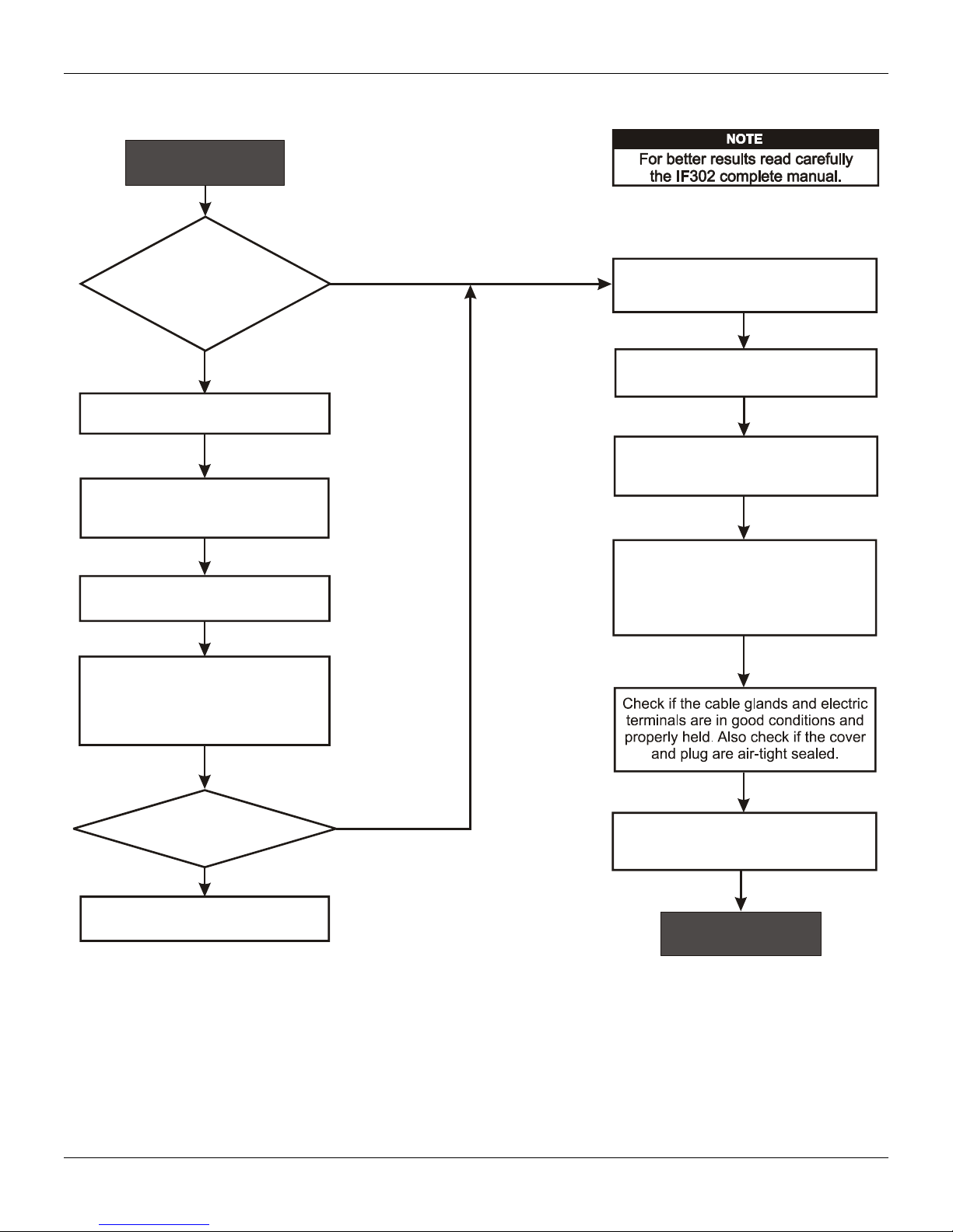
Kpuvcnncvkqp"Hnqyejctv"
Start
Kpuvcnncvkqp"Hnqyejctv"
"
Was the converter
configured on the bench
to match the application?
No
Configure the engineering unit.
Configure the terminal(s)
and input scale(s) .
(Section 3 - Calibration)
Configure the LCD reading.
(Section 3 - Configuration)
Simulate the value(s) in the 4 a
20 mA input and verify the
signal(s) in Fieldbus.
Yes
Install the converter on the field
following the instructions below.
Install the preferably
converter
on wether-protected areas.
Check the area classification
and its practices.
Install the (mechanically
converter
and electrically) according to the
application after checking the best
position for the LCD
(Section 4 - Maintenance).
Is the indication correct?
No
See section 4 - Maintenance
Yes
Energize the properly.
converter
IF302 needs a external power supply
for supply the equipment .
4 - 20 mA
OK
XKK"
Page 8

KH524"⁄"Qrgtcvkqp"cpf"Ockpvgpcpeg"Kpuvtwevkqp"Ocpwcn"
XKKK"
Page 9

Section 1
General
Mounting
Electric Wiring
INSTALLATION
NOTE
The installation carried out in hazardous areas should follow the recommendations of the IEC60079-14
standard.
The overall accuracy of measurement and control depends on several variables. Although the
converter has an outstanding performance, proper installation is essential, in order to maximize its
performance.
Among all factors, which may affect converter accuracy, environmental conditions are the most
difficult to control. There are, however, ways of reducing the effects of temperature, humidity and
vibration.
Locating the converter in areas protected from extreme environmental changes can improve the
converter performance.
In warm environments, the converter should be installed to avoid as much as possible, direct
exposure to the sun. Installation close to lines and vessels subjected to high temperatures shou ld
also be avoided.
Use of sunshades or heat shields to protect the converter from external heat sources should be
considered, if necessary.
Humidity is fatal to electronic circuits. In areas subjected to high relative humidity, the O-rings for the
electronics cover must be correctly placed. Removal of the electronics cover in the fiel d should be
reduced to the minimum necessary, since each time it is removed the circuits are exposed to the
humidity. The electronic circuit is protected by a humidity proof coatin g, but frequent exposures to
humidity may affect the protection provided. It is also important to keep the covers tightened in
place. Every time they are removed, the threads are exposed to corrosion, since painting cannot
protect these parts. Code-approved sealing methods on conduit enteri ng the converter should be
employed.
Using the bracket, the mounting may be done in several positions, as shown on Figure 1.3 Dimensional Drawing and Mounting Positions.
For better visibility, the digital indicator may be rot ated in steps of 90 (See Section 4 - Maintenance
Procedures).
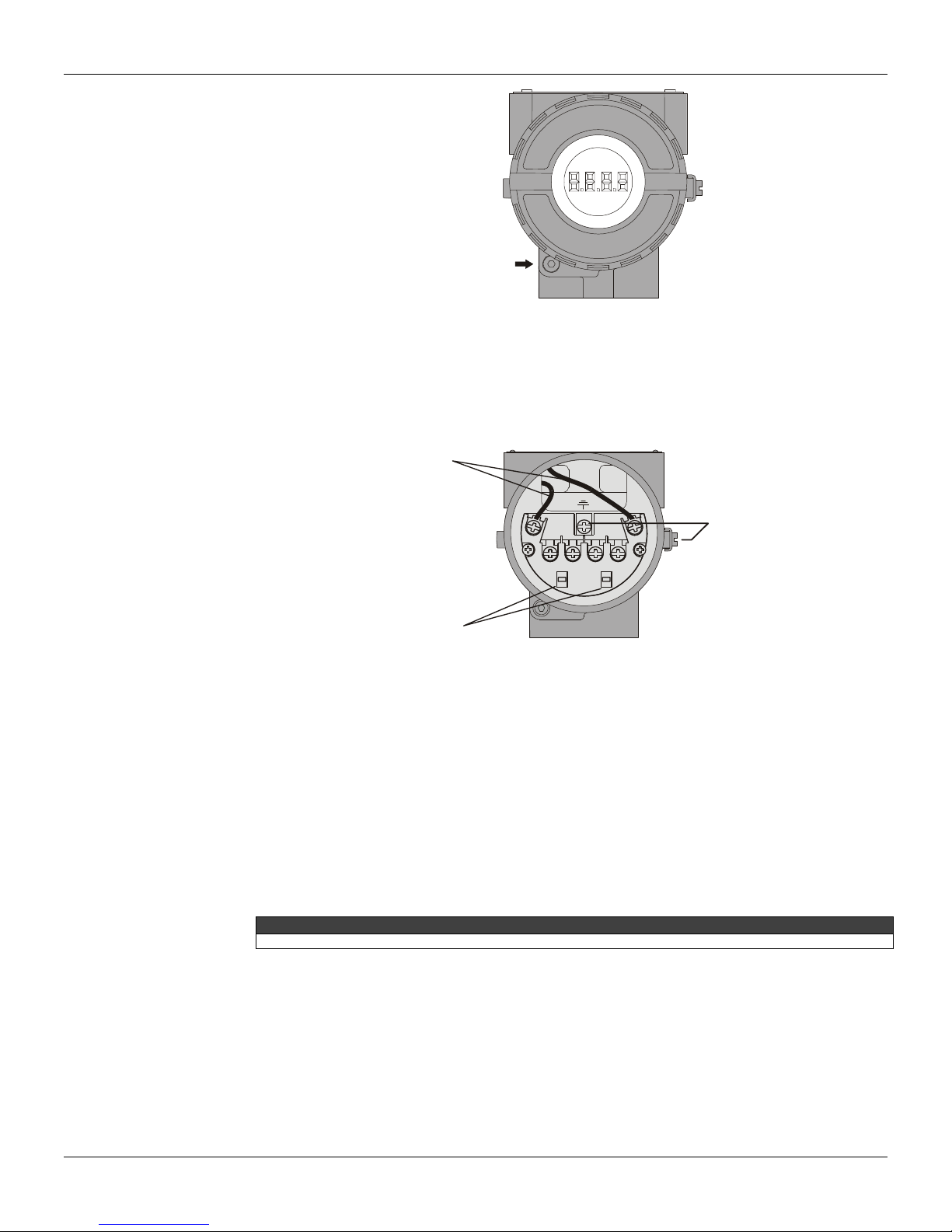
Access the wiring block by removing the Electrical Connection Cover. This cover can be locked
closed by the cover locking screw (See Figure 1.1 - Cover Locking). To release the cover , rotate the
locking screw clockwise.
Cable access to wiring connections is obtained by one of the two conduit outlets. Con duit threads
should be sealed by means of code-approved sealing methods. The unused outlet connection
should be plugged accordingly.
1.1
Page 10
IF302 - Operation and Maintenance Instruction Manual
L
R
COVER
LOCKING
SCREW
Figure 1.1 - Cover Locking
For convenience there are three ground terminals: one inside the cover and two externals, located
close to the conduit entries.
The wiring block has screws, on which fork or ring type terminals can be fastened, see Figure 1.2 Terminal Block.
POWE
SUPPLY
TERMINALS
GROUND
TERMINA
COMUNICATION
TERMINALS
Figure 1.2 - Terminal Block
The IF302 uses the 31.25 kbi t/s voltage mode option for the phys ical signaling. All other devices on
the same bus must use the same signaling. 12 to 16 devices can be connected in parallel alon g the
same pair of wires.
Various types of Fieldbus devices may be connected on the same bus.
The IF302 is powered via the bus. The limit for such devices is 16 for o ne bus (one segment) for
non-intrinsically safe requirement.
In hazardous area, the number of devices may be limited by intrinsically safe restrictions.
The IF302 is protected against reverse polarity, and can withstand ±35 VDC without damage.
NOTE
Please refer to the General Installation, Operation and Maintenance Manual for more details.
1.2
Page 11
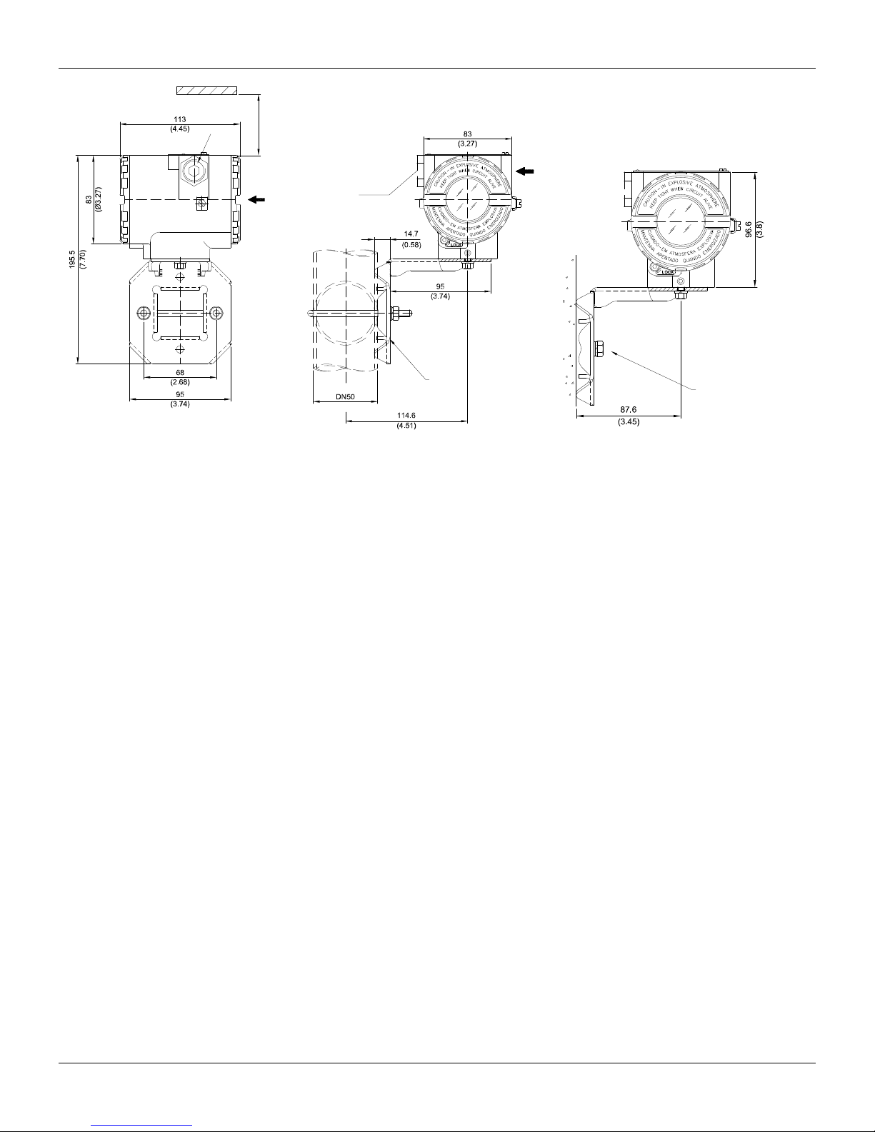
Installation
ALLOW 150 MM MINIMUM FOR LOCAL
ZERO AND SPAN ADJUSTMENT WITH
PLUG
MAGNETIC TOOL.
COMMUNICATIONS
TERMINAL
PLUG
CONDUIT
CONNECTION
WALL OR
PANEL MOUNTING
PIPE 2"
Figure 1.3 - Dimensional Drawing and Mounting Positions
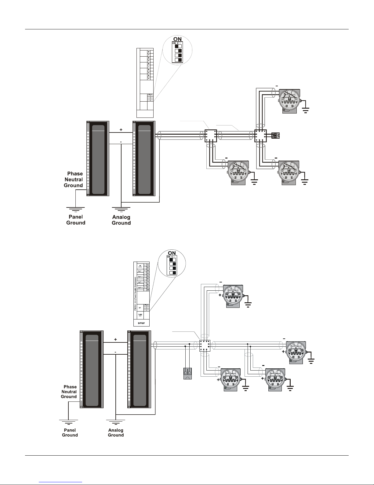
Topology and Network Configuration
Bus topology (See Figure 1.4 - Bus Topology) and tre e topology (See Figure 1.5 - Tree Topology
Configuration) are supported. Both types have a trunk cable with two terminations. T he devices are
connected to the trunk via spurs. The spurs may be i ntegrated in the device giv ing zero spur l ength.
A spur may connect more than one device, dependin g on the length. Active couplers may be us ed
to extend spur length.
Active repeaters may be used to extend the trunk length.
The total cable length, including spurs, between any two devices in the Fieldbus sho uld not exceed
1900m.
MOUNTING
BRACKET
FOR WALL MOUNTING
2 EXPANSION ANCHOR 2 HEXAGON SCREW -
FOR PANEL MOUNTING
2 BOLT AND NUTS - 1/4”X30
NOT INCLUDED
S8
3/16”X70
1.3
Page 12
IF302 - Operation and Maintenance Instruction Manual
1A
IN
24VDC
2A
3A
OUT 1
Fieldbus H1
4A
5A
OUT 2
Fieldbus H1
6A
7A
OUT 3
Fieldbus H1
8A
9A
OUT 4
Fieldbus H1
10A
BT
PSI302 3.0 (Power Supply Impedance)
FUSE
2,5A
smar
PS302
ON
FAIL
PSI302
ON
FAIL 1
FAIL 2
FAIL 3
FAIL 4
Terminator
Enabled
Junction
Box
Spur
+
Shield
Terminator
++
Spur
smar
Spur
smar
Figure 1.4 - Bus Topology
Terminator
Enabled
Junction
Box
PS302
ON
FAIL
PSI302
ON
FAIL 1
FAIL 2
FAIL 3
FAIL 4
Coupler
smar
1.4
smar
Figure 1.5 - Tree Topology Configuration
Page 13
302
CO
3
Input Wiring
+
Installation
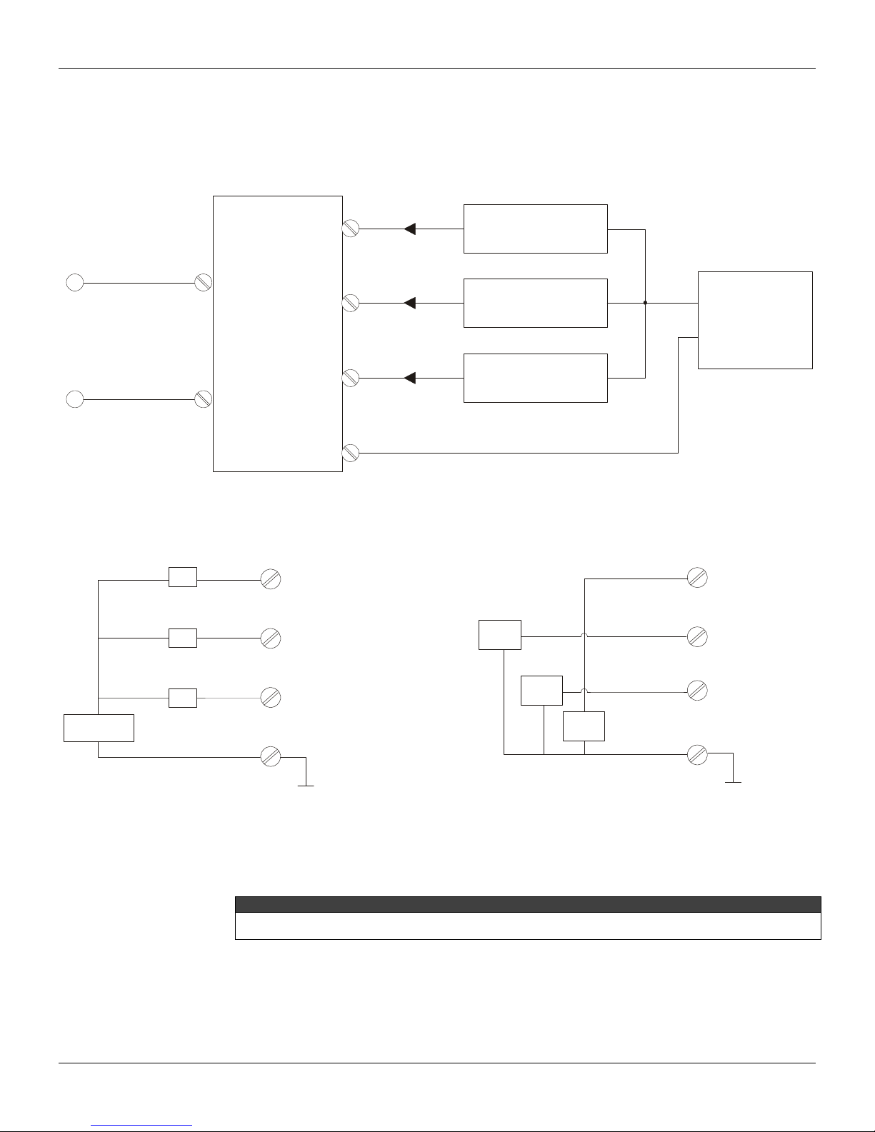
The IF302 accepts up to three current inp uts in the range 0-20 mA or 4-20 mA. The three inputs
have a common ground and they are protected from rever se polarity signal. The inputs should be
connected as per Figure 1.6 - Input Wiring.
IF
4 a 20mA
1
TRANSMITTER 1
+
FIELDBUS
+
Power
Supply
-
+
+
+
4-20mA
TR
TR
TR
2
TRANSMITTER 2
_
3
TRANSMITTER 3
+
+
+
_
POWER
SUPPLY
4
Figure 1.6 - Input Wiring
Note that IF302 can operate with 0-20 mA or 4-20mA transmitters (See Figure 1.7 - Connection).
11
-
-
-
CHANNEL1
22
CHANNEL 2
0-20mA
+
+
3
CHANNEL 3
44
COMMON
0-20mA
-
+
0-20mA
-
4-wire 0-20mA Transmitters or
0-20mA Current Generator
3
CHANNEL1
CHANNEL 2
CHANNEL
COMMON
TR = Transmitter
Avoid routing input wiring close to power cables or switching equipment.
Apply in the inputs of the conversor only current levels. Don't apply tension levels, because the shunt resistors
are of 100R 1W and tension above 10 Vdc it can damage them.
NNECTION
Figure 1.7 - Connection
WARNING
1.5
Page 14

IF302 - Operation and Maintenance Instruction Manual
Installation in Hazardous Areas
Explosions could result in death or serious injury, besides financial damage. Installation of this
converter in explosive areas must be carri ed out in accordance with the local standards and the
protection type adopted .Before continuing the i nstallation make sure the certificate parameters are
In accordance with the classified area where the equipment will be installed.
The instrument modification or parts replacement suppl ied by other than authorized representativ e
of Smar is prohibited and will void the certification.
The converters are marked with options of the protection type. T he certification is valid only when
the protection type is indicated by the user. Once a particular type of protection is selected, any
other type of protection can not be used.
The electronic housing and the sensor installed in haz ardou s areas must h ave a minim um of 6 full y
engaged threads. Lock the housing using the locking screw (Figure 1.1).
The cover must be tighten with at least 8 turns to avoi d the penetration of humidity or corrosive
gases. The cover must be tighten until it touches the housing. Then, tight en more 1/3 turn (12 0) to
guarantee the sealing. Lock the covers using the locking screw (Figure 1.1).
Consult the Appendix A for further information about certification.
Explosion/Flame Proof
In Explosion-Proof installations the cable entries must be connected or c losed using metal cable
gland and metal blanking plug, both with at least IP66 and Ex-d certification.
The standard plugs provided by Smar are certifie d according to CEPEL certificate. If the plug
needs to be replaced, a certified plug must be used.
The electrical connection with NPT thread must use waterproofing sealant. A non-hardening
silicone sealant is recommended.
For NEMKO ATEX certificate please to follow the installation guide lines in hazardous locations
below: Group II Category 2G, Ex d, Group IIC, Temperature Class T6, EPL Gb U = 28VDC
Ambient Temperature: -20 to 60ºC for T6
Environmental Protection: IP66/687 or IP66W/687W
The electrical connection available are ½ - 14NPT and M20x1,5.
Cable entries must be connected or closed using metal cable gland and metal blanking plug,
both with at least IP66 and Ex-d certification or any appropriate ATEX approved metal cable
gland and metal blanking plug. Do not remove the transmitter covers when power is ON.
Intrinsically Safe
In hazardous zones with intrinsically safe or non-incendive requirements, the circuit entity
parameters and applicable installation procedures must be observed.
To protect the application the transmitter must be connected to a barrier. Match the parameters
between barrier and the equipment (Consider the cable parameters). Associated apparatus
ground bus shall be insulated from panels and mounting enclosures. Shield is optional. If used, be
sure to insulate the end not grounded. Cable capacitance and inductance plus Ci and Li must be
smaller than Co and Lo of the associated Apparatus.
It is not recommended to remove the transmitter cover when the power is ON.
WARNING
WARNING
WARNING
1.6
Page 15

Section 2
OPERATION
The IF302 accepts signals from mA generators such as most conventional transmitters. It is
therefore ideal for interfacing existing equipment to a Fieldbus system.
Functional Description – Electronics
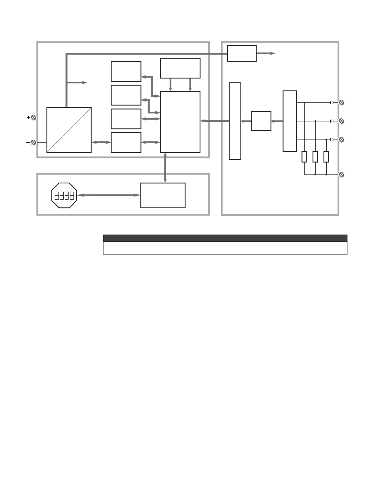
Refer to the block diagram (See Figure 2.1 - IF302 Block Diagram). The function of each block is
described below.
MUX Multiplexer
The MUX multiplexes the input terminals to ensure that all three channels reach the A/D converter.
A/D Converter
The A/D converts the input signals to a digital format for the CPU.
Signal Isolator
Its function is to isolate the data signal between the input and the CPU.
(CPU) Central Processing Unit, RAM and FLASH
The CPU is the intelligent portion of the converter, being responsible for the management and
operation of block execution, self-diagnostics and comm unication. The program is stored in Flash
memory. For temporary storage of data there is a RAM. The data in the RAM is lost if the po wer is
switched off, however the device also has a nonvolatile EEPROM where data that must be retained
are stored. Examples of such data are: calibration, configuration and identification data.
Communication Controller
It monitors line activity, modulates and demodulates the signal from network line.
Power Supply
Takes power of the loop-line to power the converter circuitry.
Power Isolation
Just like the signals from the input section, the power to the input section must be isolated.
Display Controller
Receives data from the CPU and drives the Liquid Crystal Display.
Local Adjustment
They are two switches that are magnetically activated. They can be activ ated by the magnetic tool
without mechanical or electrical contact.
2.1
Page 16
IF302 – Operation and Maintenance Instruction Manual
4
MAIN CIRCUIT BOARD INPUT CIRCUIT BOARD
POWER
ISOLATION
POWER
SUPPLY
SIGNAL
SHAPING
SUPPLY
FIRMWARE
DOWLOAD
INTERFACE
FLASH
RAM
MODEM
LOCAL ADJUST
CPU
EEPROM
S
I
G
N
A
L
3 x 100
M
U
X
I
S
O
L
A
T
I
O
N
A/D
(*) Resistor Shunt
1
2
3
DISPLAY BOARD
DISPLAY
CONTROLLER
Figure 2.1 - IF302 Block Diagram
* WARNING
Apply in the inputs of the conversor only current levels. Don't apply tension levels, because the shunt
resistors are of 100R 1W and tension above 10 Vdc it can damage them.
2.2
Page 17

Section 3
CONFIGURATION
One of the many advantages of Fieldbus is that device configuration is independent of the
configurator. The IF302 may be configured by a third party terminal or operator console.
The IF302 contains three input transducer blocks, one resource block, one display transducer block
and function blocks.
Function Blocks are not covered in this manual. For explanation and details of function blocks, see
the “Function Blocks Manual”.
Transducer Block
Transducer block insulates function block from the specific I/O hardware, such as sensors and
actuators. Transducer block controls access to I/O through manufacturer specific implementation.
This permits the transducer block to execute as frequently as necessary to obtain good data from
sensors without burdening the function blocks that use the data. It also insulates the function blocks
from the manufacturer specific characteristics of certain hardware.
By accessing the hardware, the transducer block can get data from I/O or passing control data to it.
The connection between Transducer block and Input/Output Function blocks is called channel.
Normally, transducer blocks perform functions, such as linearization, characterization, temperature
compensation, control and exchange data to/from hardware.
How to Configure a Transducer Block
The transducer block has an algorithm, a set of contained parameters and a channel connecting it to
a function block.
The algorithm describes the behavior of the transducer as a data transfer function between the I/O
hardware and other function block. The set of contained parameters, it means, you are not able to
link them to other blocks, defines the user interface to the transducer block. They can be divided into
Standard and Manufacturer Specific.
The standard parameters will be present for such class of device, as pressure, temperature,
actuator, etc., whatever is the manufacturer. Oppositely, the manufacturers specific ones are
defined only by its manufacturer. As common manufacturer specific parameters, we have calibration
settings, material information, linearization curve, etc.
When you perform a standard routine as a calibration, you are conducted step by step by a method.
The method is generally defined as guide line to help the user to make common tasks. The
SYSCON configurator identifies each method associated to the parameters and enables the
interface to it.
Terminal Number
The terminal number, which references a physical input, which is sent internally from the specified
transducer output to function block.
It starts at one (1) for transducer number one until three (3) for transducer number three.
The channel number of the AI block is related to the transducer’s terminal number. Channel number
1, 2, 3 corresponds bi-univocally to the terminal block with the same number. Therefore, all the user
has to do is to select combinations: (1.1), (2.2), (3,3) for (CHANNEL, BLOCK).
3.1
Page 18

IF302 - Operation and Maintenance Instruction Manual
Primary Value Status
The status of the Primary Value can follow the NAMUR NE 43 as showed bellow:
3.80 mA < input < 20.5 mA GOOD
input = 3.80 mA or input = 20.5 UNCERTAIN
input <= 3.6 mA or input >= 21.0 mA BAD
To disable this feature, just write a number different from 4 or 20 in the Transducer xd_scale
parameter.
Current Trim
The IF302 provides the capability of making a trim in the input channels, if necessary.
A trim is necessary if the indicator reading of the transducer block output differs from the actual
physical output. The reason may be:
The user's current meter differs from the factory standard.
The converter had its original characterization shifted by over-load or by long term drift.
The user can check the calibration of the transducer output by measuring the actual current in the
input and compare it with the device’s indication (of course an appropriate meter shall be used). If a
mismatch is detected, a trim can be done.
Trim can be done in two points:
Lower Trim: Is used to trim the output at the lower range.
Upper Trim: Is used to trim the output at the upper range.
These two points define the linear characteristic of the output. Trim in one point is independent from
the other.
There are at least two ways of doing the trim: using local adjustment or using SYSCON (the System
Configurator from SMAR).
When doing the trim, make sure you are using an appropriate meter (with the necessary accuracy).
Via SYSCON
The channel number of the AI block is related to the transducer’s terminal block number. Channel
number 1,2,3 corresponds bi-univocally to the terminal block with the same number. Therefore, all
the user has to do is to select combinations: (1,1), (2,2), (3,3), for (CHANNEL, TERMINAL
NUMBER).
3.2
Page 19
Configuration
This parameter
selects the
terminal number
which the input
current will be
generated and
calibrated.
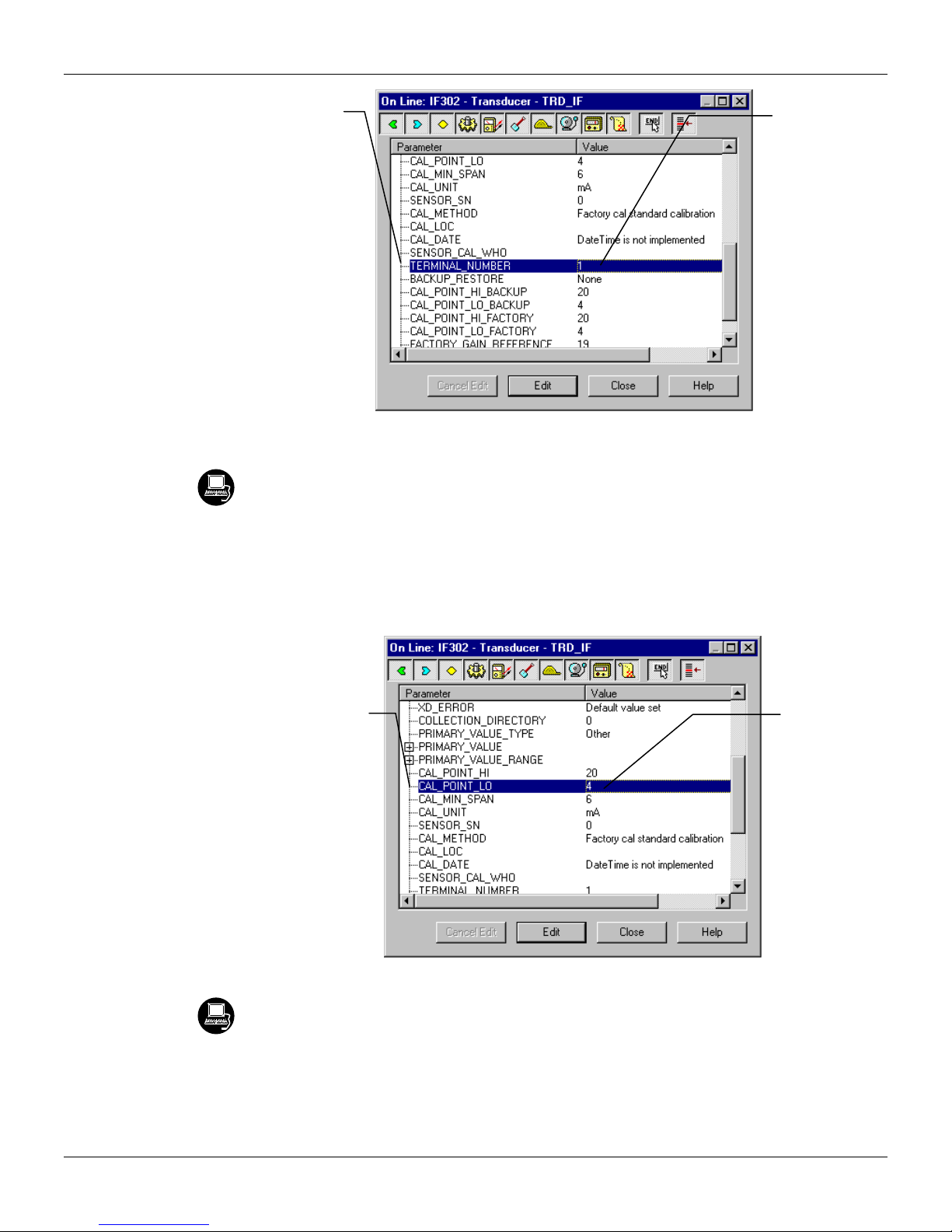
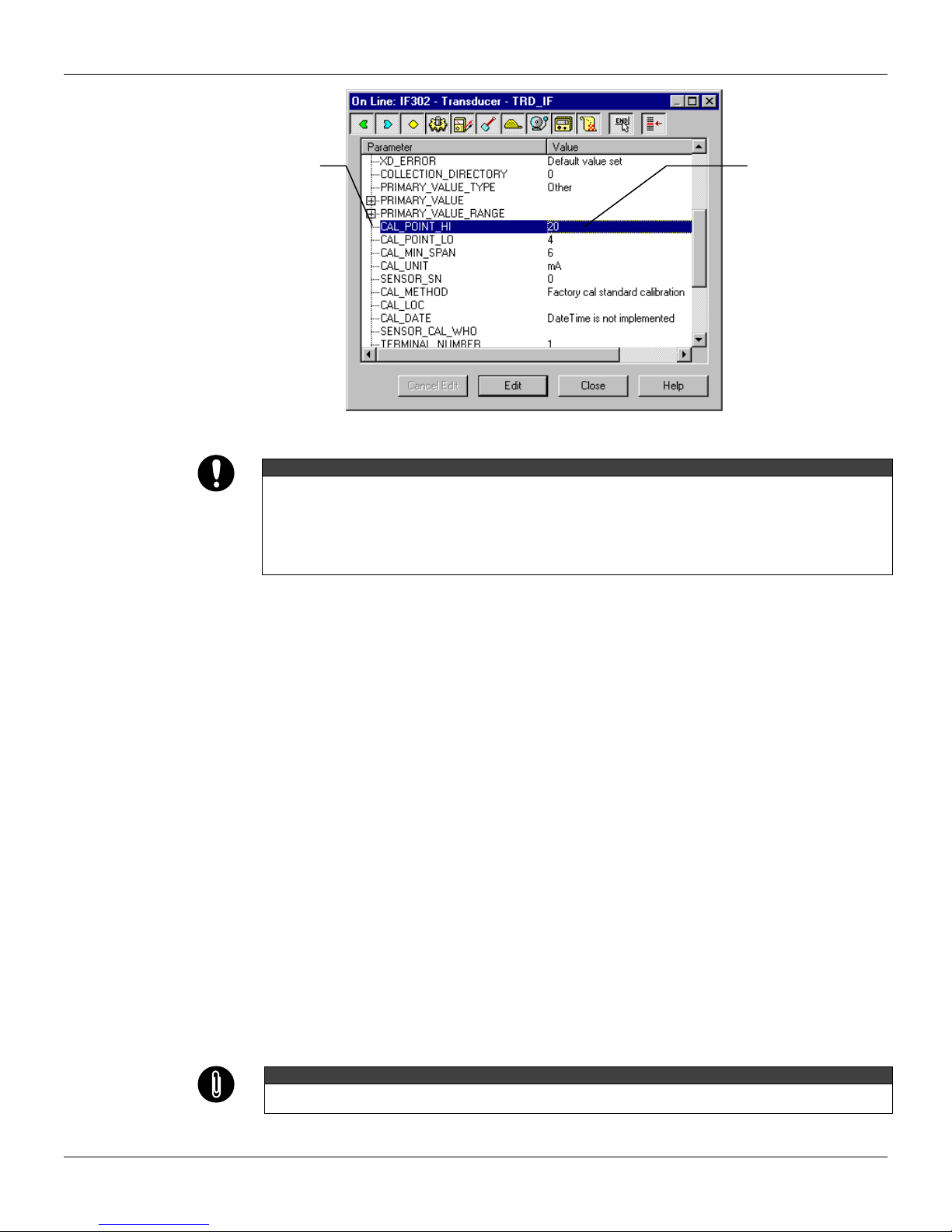
It is possible to calibrate the current inputs of the transmitter by means of parameters
CAL_POINT_LO and CAL_POINT_HI.
Let’s take the lower value as an example:
Supply 4 mA or the lower value to the terminal block and wait until the readout of parameter
PRIMARY_VALUE stabilizes.
Write 4.00 or the lower value in parameter CAL_POINT_LO. For each value written a calibration is
performed at the desired point.
In this case the
channel 1 was
chosen.
Figure 3.1 - Current Trim - IF302
This parameter
indicates where the
converter should be
when the setpoint
lower value is 0%.
Let’s take the upper value as an example:
Supply 20 mA or the upper value to the terminal block and wait until the readout of parameter
PRIMARY_VALUE stabilizes.
Write 20.00 or the upper value in parameter CAL_POINT_HI. For each value written a calibration is
performed at the desired point.
The desired
value should be
entered.
Figure 3.2 - Current Trim - IF302
3.3
Page 20
IF302 - Operation and Maintenance Instruction Manual
This parameter
indicates where the
converter should be
when the setpoint is
100%.
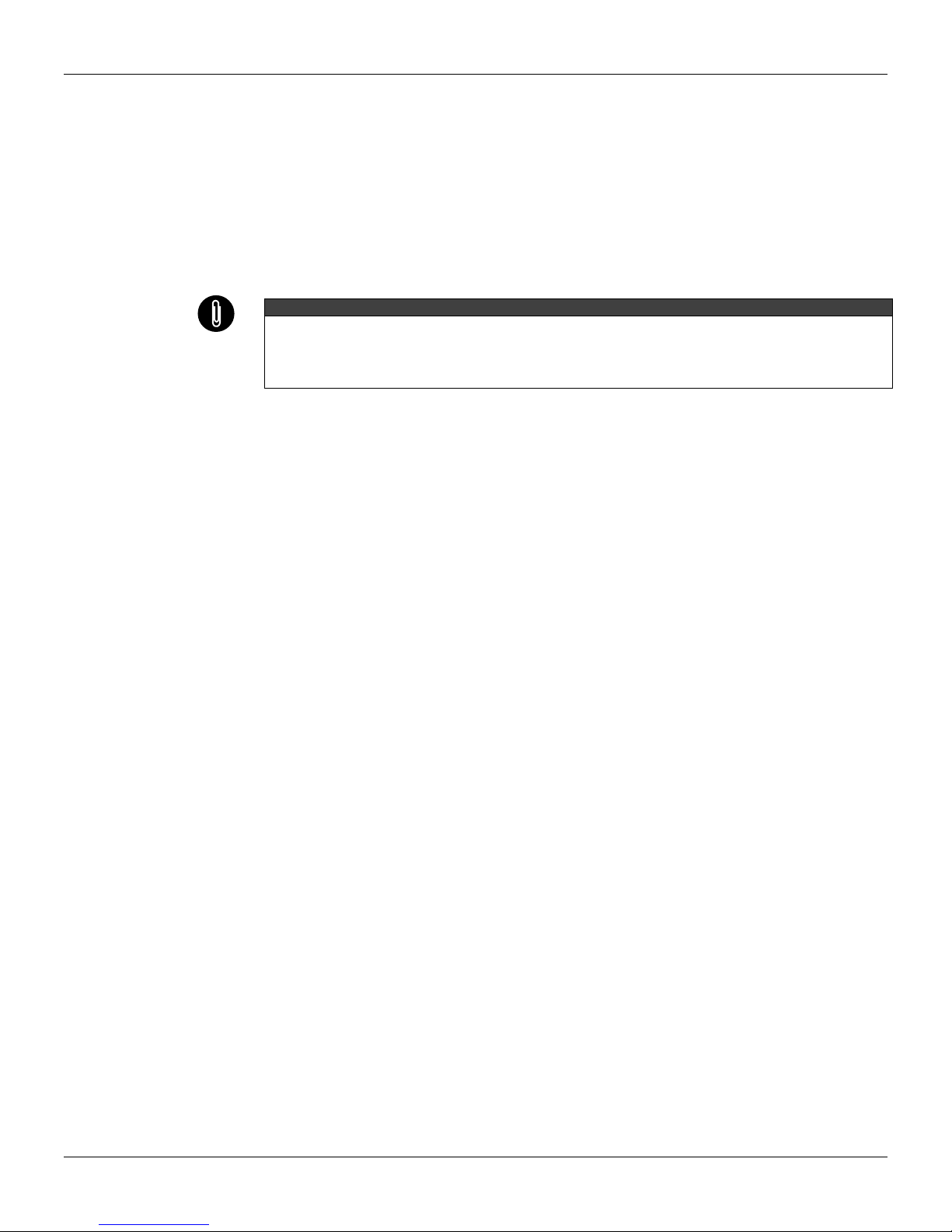
It is recommendable that a convenient engineering unit be chosen by means of parameter XD_SCALE of the
Analog Input Block, considering that the range limits of the sensor must be respected, these being 100% and
0%.
It is also recommendable, for every new calibration, to save existing trim data in parameters
CAL_POINT_LO_BACKUP and CAL_POINT_HI_BACKUP, by means of parameter BACKUP_RESTORE,
using option LAST_TRIM_BACKUP.
Via Local Adjustment
The IF302 has 3 input transducers and its device leaves SMAR with factory settings. The factory
setting establishes only the transducers #1 as default for local adjustment. In order to configure the
others via local adjustment, the user should configure them in the display transducer via SYSCON,
according specific instructions for this transducer block.
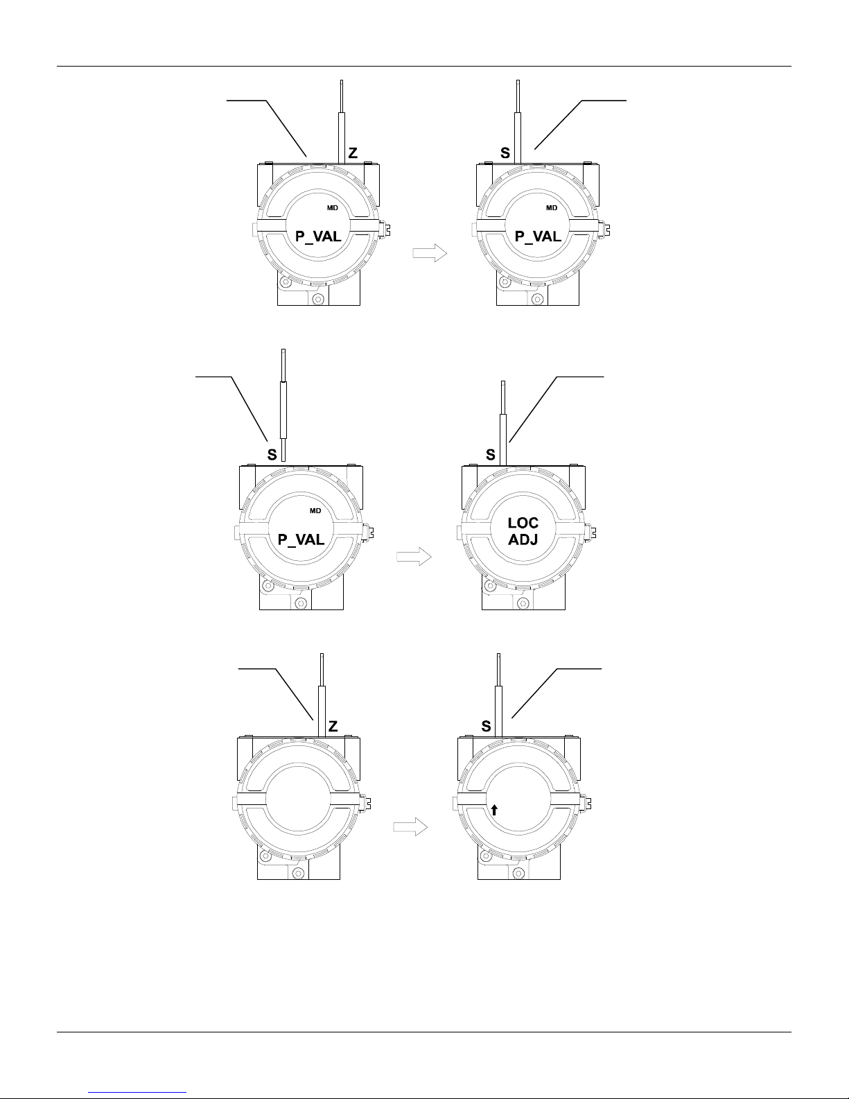
In order to enter the local adjustment mode, place the magnetic tool in orifice “Z” until flag “MD”
lights up in the display. Remove the magnetic tool from “Z” and place it in orifice “S” until the
message “LOC ADJ” is displayed. The message will be displayed during approximately 5 seconds
after the user removes the magnetic tool from “S”. By placing the magnetic tool the user will be able
to access the local adjustment tree in the monitoring mode.
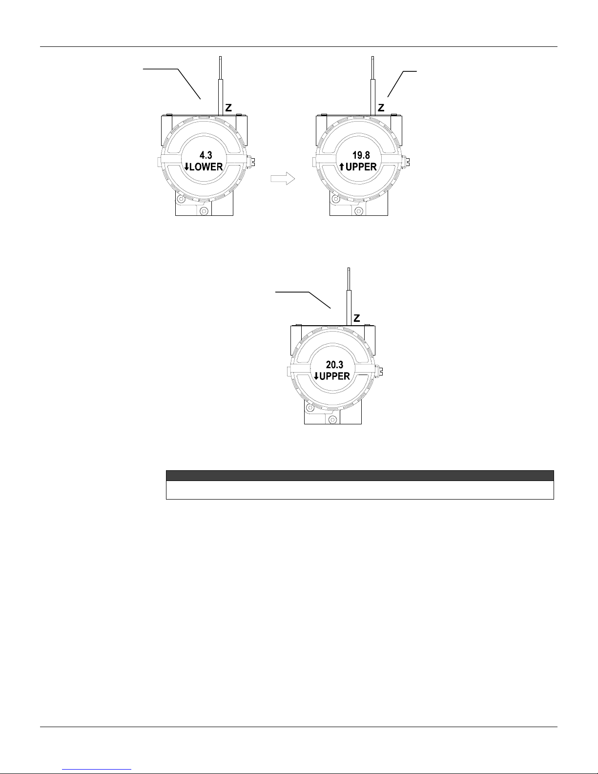
Browse to parameter P_VAL (PRIMARY_VALUE).
Supply 4.0mA or the lower value to the terminal block and wait until the read of the parameter
stabilizes in the display.
Browse to parameter “LOWER”. After that, in order to start calibration, the user will act on the
parameter “LOWER” by placing the magnetic tool in “S” down to 4.0 mA.
Let’s take the upper value:
Supply 20.0mA or the upper value to the terminal block and wait until the readout of parameter
P_VAL stabilizes, and then actuate parameter UPPER up to 20.0.
Trim mode exits via local adjustment automatically when the magnetic tool is not used during
approximately 16 seconds.
Keep in mind that even when parameters LOWER or UPPER present the desired value, they must be actuated
so that calibration is performed.
The desired value
should be entered.
Figure 3.3 - Current Trim - IF302
WARNING
NOTE
3.4
Page 21
Limit Conditions for Calibration:
For every writing operation in the transducer blocks there is a code indication for the operation
associated with the writing method. These codes appear in parameter XD_ERROR every time a
calibration is performed. Code 16, for example, indicates a successfully performed operation.
Lower:
0.0mA < NEW_ LOWER < 9.0mA
Otherwise, XD_ERROR = 22
Upper:
15.0 mA < NEW_UPPER < 22.0mA
Otherwise, XD_ERROR = 22.
Codes for XD_ERROR:
… 16: Default Value Set
… 22: Out of range
… 26: Invalid Calibration request
… 27: Excessive Correction
Display Transducer Block
The local adjustment tree is completely configured by SYSCON. It means, the user can select the
best options to fit his application. From factory, it is configured with the options to set the Upper and
Lower trim, for monitoring the input transducer output and check the Tag. Normally, the transmitter
is much better configured by SYSCON, but the local functionality of the LCD permits an easy and
fast action on certain parameters, since it does not rely on communication and network wiring
connections. Among the possibilities by Local Adjustment, the following options can be emphasized:
Mode block, Outputs monitoring, Tag visualization and Tuning Parameters setting.
The interface between the user is described very detailed on the "General Installation, Operation
and Maintenance Procedures Manual". Please take a detailed look at this manual in the chapter
related to "Programming Using Local Adjustment". It shows significantly the resources on this
transducer display. All Series 302 field devices from SMAR have the same methodology to handle
with it. So, since the user has learned once, he is capable to handle all kind of field devices from
SMAR.
All function blocks and transducers defined according Foundation Fieldbus have a description of
their features written on binary files, by the Device Description Language. This feature permits that
third parties configurator enabled by Device Description Service technology can interpret these
features and make them accessible to configure. The Function Blocks and Transducers of Series
302 have been defined rigorously according the Foundation Fieldbus specifications in order to be
interoperable to other parties.
In order to enable the local adjustment using the magnetic tool, it is necessary to previously prepare
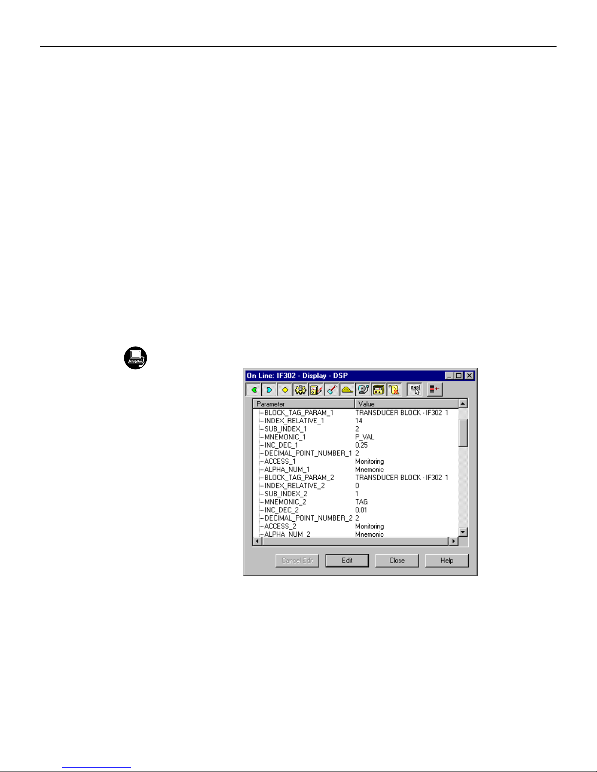
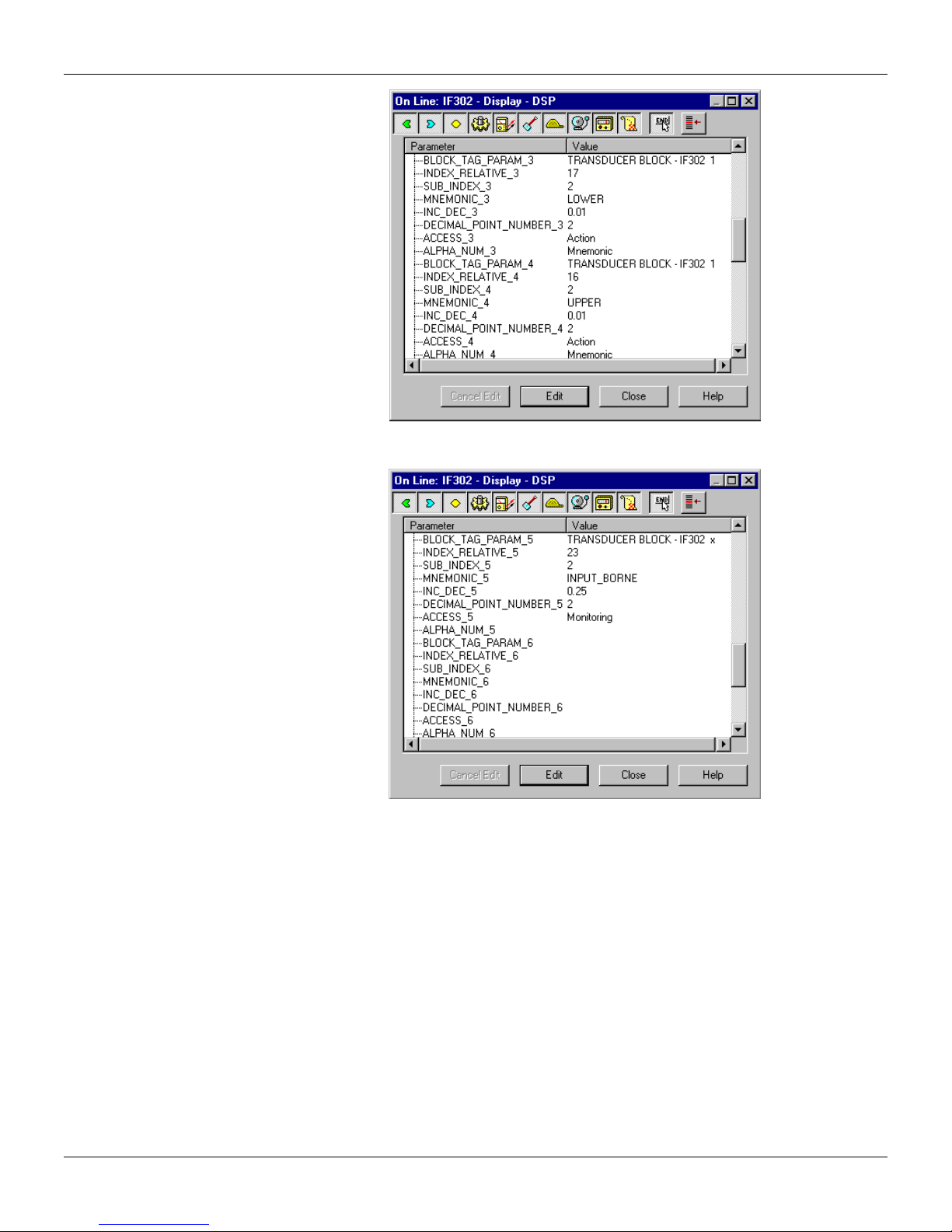
the parameters related with this operation via SYSCON (System Configurator). The Figure 3.8 -
Parameters for Local Adjustment Configuration and the Figure 3.11 - Step 1 - IF302 show all
parameters and their respective values, which shall be configured in accordance with the necessity
of being locally adjusted by means of the magnetic tool. All values shown on the display are default
values.
There are seven groups of parameters, which may be pre-configured by the user in order to allow a
possible configuration by means of the local adjustment. As an example, let’s suppose that you
don’t want to show some parameters; in this case, simply write an invalid Tag in the parameter,
Block_Tag_Param_X. Doing this, the device will not take the parameter related (indexed) to the Tag
as a valid parameter.
Definition of Parameters and Values
Block_Tag_Param
This is tag of the block to which the parameter belongs. Use up to a maximum of 32 characters.
Index_Relative
This is the index related to the parameter to be actuated or viewed (0, 1, 2…). Refer to the Function
Blocks Manual to know the desired indexes, or visualize them on the SYSCON by opening the
desired block.
Configuration
NOTE
3.5
Page 22
IF302 - Operation and Maintenance Instruction Manual
Sub_Index
In case you wish to visualize a certain tag, opt for the index relative equal to zero, and for the subindex equal to one (refer to paragraph Structure Block in the Function Blocks Manual).
Mnemonic
This is the mnemonic for the parameter identification (it accepts a maximum of 16 characters in the
alphanumeric field of the display). Choose the mnemonic, preferably with no more than 5 characters
because, this way, it will not be necessary to rotate it on the display.
Inc_Dec
It is the increment and decrement in decimal units when the parameter is Float or Float Status time,
or integer, when the parameter is in whole units.
Decimal_Point_Number
This is the number of digits after the decimal point (0 to 3 decimal digits).
Access
The access allows the user to read, in the case of the “Monitoring” option, and to write when "action"
option is selected, then the display will show the increment and decrement arrows.
Alpha_Num
These parameters include two options: value and mnemonic. If option value is selected, the display
will show data both in the alphanumeric and in the numeric fields; this way, in the case of a data
higher than 10000, it will be shown in the alphanumeric field.
If option mnemonic, the display will show the data in the numeric field and the mnemonic in the
alphanumeric field.
In case you wish to visualize a certain tag, opt for the index relative equal to zero, and for the subindex equal to one (refer to paragraph Structure Block in the Function Blocks Manual).
3.6
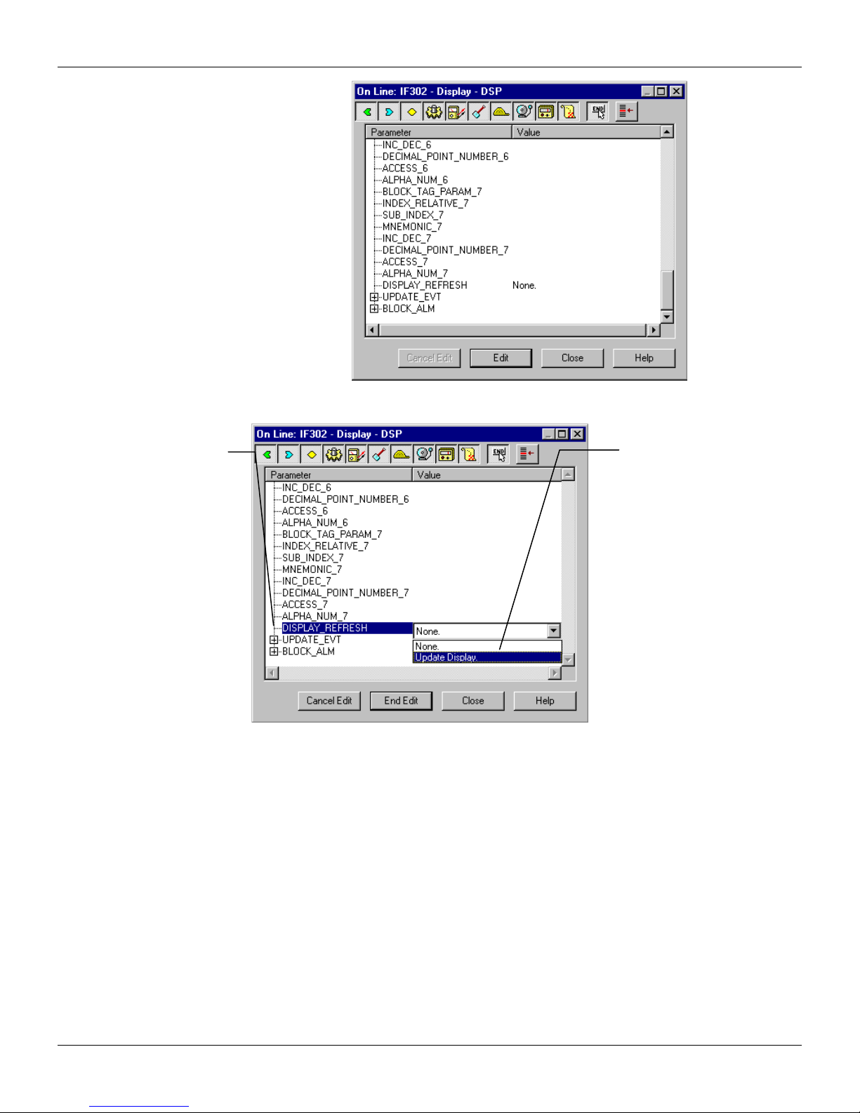
Figure 3.4 - Parameters for Local Adjustment Configuration
Page 23
Configuration
Figure 3.5 - Parameters for Local Adjustment Configuration
Figure 3.6 - Parameters for Local Adjustment Configuration
3.7
Page 24
IF302 - Operation and Maintenance Instruction Manual
Figure 3.7 - Parameters for Local Adjustment Configuration
This parameter
updates the local
adjustment
programming tree
configured on each
device.
Figure 3.8 - Parameters for Local Adjustment Configuration
Programming Using Local Adjustment
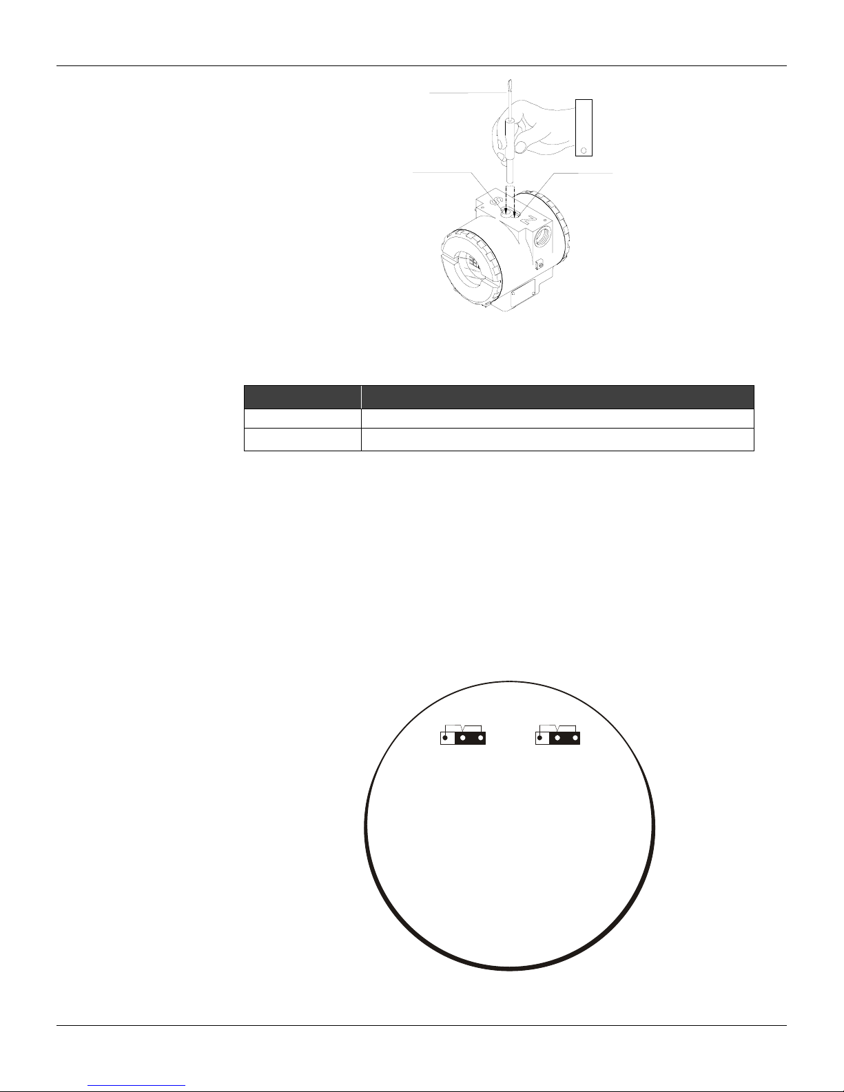
The converter has two holes for magnetic switches activated by the magnetic tool located under the
identification plate (See Figure 3.9). These magnetic switches are activated by one magnetic tool.
This magnetic tool enables adjustment of the most important parameters of the blocks. It also
enables pre-configuration of the communication.
The jumper J1 on top of the main circuit board must be in place for this function to be enabled and
the transmitter must be fitted with the digital display for access to the local adjustment. Without the
display the local adjustment is not possible.
The option "update" should
be selected in order to
execute the upgrade of local
adjustment programming
tree.
After its step all the
parameters selected will be
show on the LCD display.
3.8
Page 25
Configuration
A
Magnetic Tool
Table 3.1 shows the actions on the Z and S holes on the LD302 when Local Adjustment is enabled.
J1 Jumper Connections
If J1 (see figure 3.10) is connected to ON, it is possible to simulate values and status through the
SIMULATE parameter, from the function blocks.
W1 Jumper Connections
If W1(see figure 3.10) is connected to ON, the local adjustment programming tree is enabled, the
block parameters can be adjusted and the communication can be pre-configured via local
adjustment.
Span Hole
Fig. 3.9 - Local Adjustment Holes
HOLE ACTION
Z Initializes and rotates through the available functions.
S Selects the function shown in the display.
Table 3.1 - Purpose of the holes on the Housing
Zero Hole
WR
OFF
ON
J1
OFF
ON
LOC
W1
MAIN BOARD
Fig. 3.10 - J1 and W1 Jumpers
DJ
3.9
Page 26
IF302 - Operation and Maintenance Instruction Manual
n
In order to
start the local
adjustment,
place the
magnetic tool
in orifice
and wait until
letters
are
displayed.
MD
Z
5.00 5.00
Place the
magnetic
tool in orifice
S
and wait
during 5
seconds.
Remove
the
magnetic
tool from
orifice
S
.
In this option (P_VAL)
is showed with its
respective value
(if you to want that it
keeps static, put the
tool in S orifice and
stay there.
5.00
5.00
P_VAL
Figure 3.11 - Step 1 - IF302
Figure 3.12 - Step 2 - IF302
Figure 3.13 - Step 3 - IF302
3.8
LOWER
Insert the
magnetic
tool in orifice
S
once more
and
LOC
ADJ
should
be
displayed.
This parameter is
used to calibrate the
lower current point. I
order to range the
lower value, simply
insert the magnetic
S
tool in orifice
as
soon as lower is
shown on the display.
An arrow pointing
upward ( ) increment
the value and an
arrow pointing
downward (
)
decrement the value.
3.10
Page 27
Configuration
In order to
decrement
the lower
value, place
the magnetic
tool in orifice
Z
to shift the
arrow to the
downward
position and
then, by
inserting and
keeping the
tool in orifice
S
, it is
This parameter is used
to calibrate the upper
current point. In order
to range the upper
value, simply insert the
magnetic tool in orifice
S
as soon as upper is
shown on the display.
An arrow pointing
upward ( ) increment
the value and an arrow
pointing downward (
)
decrement the value.
Apply the 20.0 mA
current in the
Figure 3.14 - Step 4 - IF302
1
and
4
a) In order to
decrement the
address value,
place the
magnetic tool in
orifice
Z
to shift
the arrow to the
downward
position and then,
by inserting and
keeping the tool in
orifice
S
, it is
possible to
Figure 3.15 - Step 5 - IF303
NOTE
This Local adjustment configuration is a suggestion only. The user may choose his preferred configuration
via SYSCON, simply configuring the display block (refer to paragraph Display Transducer Block ).
3.11
Page 28

IF302 - Operation and Maintenance Instruction Manual
3.12
Page 29

Section 4
General
Troubleshooting
MAINTENANCE
NOTE
Equipment installed in hazardous atmospheres must be inspected in compliance with the IEC60079-17
standard.
SMAR IF302 Current to Fieldbus Converters are extensiv ely tested and inspected before deliv ery to
the end user. Nevertheless, during their design and dev elopment, consideration was given to the
possibility of repairs by the end user, if necessary.
In general, it is recommended that the end user do not try to repair printed circuit boards. Instead,
he should have spare circuit boards, which may be ordered from SMAR whenever necessary.
Symptom: No Quiescent Current
Probable Sources of Trouble:
Converter Fieldbus Connections
Check wiring polarity and continuity.
Power Supply
Check power supply output. The voltage at the IF302 Fieldbus termi nals must be bet ween 9 and 32
VDC.
Electronic Circuit Failure
Check the boards for defect by replacing them with spare ones.
Symptom: No Communication
Probable Source of Trouble
Network Connections
Check the network connections: devices, power supply, and terminators.
Network Impedance
Check the network impedance (power supply impedance and terminators) .
Transmitter Configuration
Check configuration of communication parameters of converter.
Network Configuration
Check communication configuration of the network.
Electronic Circuit Failure
Try to replace the converter circuit with spare parts.
Symptom: Incorrect Inputs
Probable Source of Trouble:
Input Terminals Connection
Check wiring polarity and continuity.
Conventional Transmitter
Verify if the conventional transmitter is working properly or if it has the necessary voltage.
Remember that IF302 has a 100 ohms plus 0.8 V input impedance.
Calibration
Check calibration of IF302 and the conventional transmitters.
4.1
Page 30
IF302 - Operation and Maintenance Instruction Manual
If the problem is not presented in the table above follow the Note below:
The Factory Init should be tried as a last option to recover the equipment control when the equipment
presents some problem related to the function blocks or the communication. This operation must only be
carried out by authorized technical personnel and with the process offline, si n ce the eq uip ment will
be configured with standard and factory data.
This procedure resets all the configurations run on the equipment, after which a partial download should be
performed.
Two magnetic tools should be used to this efect,. On the equipment, withdraw the nut that fixes the
identification tag on the top of the housing, so that access is gained to the "S" and "Z" holes.
The operations to follow are:
1) Switch off the equipment, insert the magnetic tools and keep them in the holes (the magnetic end in the
holes);
2) Feed the equipment;
3) As soon as Factory Init is shown on the display, take off the tools and wait for the "5" symbol on the right
upper corner of the display to unlit, thus indicating the end of the operation.
This procedure makes effective all the factory configuration and will eliminate eventual problems with the
function blocks or with the equipment communication.
Disassembly Procedure
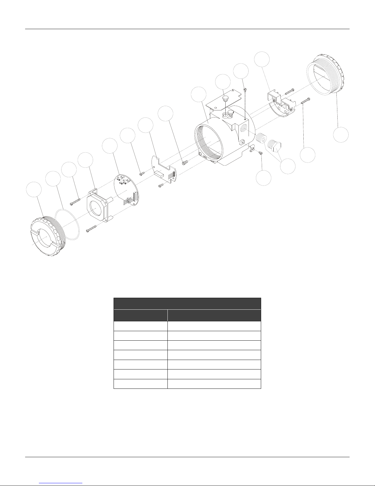
Refer to Figure 4.1 - IF302 Exploded View Make sure to disconnect power supply before
disassembling the converter.
To remove the circuit boards (5 and 7) and display (4), first loose the cov er locking (8) on the side
not marked “Field Terminals”, then unscrew the cover (1).
The boards have CMOS components, which may be damaged by electrostatic discharges. Observe correct
procedures for handling CMOS components. It is also recommended to store the circuit boards in
electrostatic-proof cases.
Loose the two screws (3) that anchors the display and the main circuit board. Gently pull out the
display, and then the main board (5). To remove the input board (7), first unscrew the two screws (6)
that anchors it to the housing (9), and gently pull out the board.
Reassemble Procedure
Put input board (7) into housing (9).
Anchors input board with their screws (6).
Put main board (5) into the housing, ensuring all inter connecting pins are connected.
Put display (4) into the housing, observing the four mounting positions. "_" should point in the
direction desired as UP.
Anchors main board and display with their screws (3).
Fit the cover (1) and lock it using the locking screw (8).
Boards Interchangeability
Main and input boards are supposed to sta y together, because calibration data from input board
circuit is stored in EEPROM of the main board.
If, for some reason, you separate the input and the main boards, you must do a trim to gua rantee p recision of
the inputs. With mismatched boards, the factory trim will not be so good as it was.
4.2
NOTE
WARNING
WARNING
Page 31
Exploded View
4
3
2
1
Maintenance
12
11
10
9
8
7
6
15
5
14
16
13
Accessories
Figure 4.1 - IF302 Exploded View
ACCESSORIES
ORDERING CODE DESCRIPTION
SD1 Magnetic Tool for Local Adjustment
BC302 Fieldbus/RS232 Interface
SYSCON System Configurator
PS302 Power Supply
PSI302 Power Supply Impedance
BT302 Terminator
PCI Process Control Interface
4.3
Page 32

IF302 - Operation and Maintenance Instruction Manual
Spare Parts List
SPARE PARTS LIST
DESCRIPTION OF PARTS POSITION CODE
Cover Without Window (Includes O-Ring)
Cover With Window for Indication (Includes O-Ring)
O-Rings (Note 2) Cover, Buna-N 2 204-0122 B
Aluminium Housing Main Board Screw
316 Stainless Steel Housing Main Board Screw
Digital Indicator 4 214-0108
Main and Input Circuit Board Assembly 5 and 7 334-0150 A
Input Board Screw
Cover Locking Screw 8 204-0120
Housing, Aluminium (Note 1)
Housing, 316 Stainless Steel (Note 1)
Local Adjustment Protection Cap 10 204-0114
Identification Plate Fixing Screw 11 204-0116
Terminal Insulator 12 314-0123
External Ground Screw 13 204-0124
Terminal Holding Screw
Six-Sided Plug 1/2" NPT Internal BR Ex
Six-Sided Plug 1/2" NPT Internal
Six-Sided Plug M20 X 1.5 External BR Ex d 316 Stainless Steel 16 400-0810
Six-Sided Plug PG13.5 External BR Ex d 316 Stainless Steel 16 400-0811
Mounting Bracket for 2” Pipe Mounting (Note 3)
Aluminium 1 and 15 204-0102
316 Stainless Steel 1 and 15 204-0105
Aluminium 1 204-0103
316 Stainless Steel 1 204-0106
Units With Indicator 3 304-0118
Units Without Indicator 3 304-0117
Units With Indicator 3 204-0118
Units Without Indicator 3 204-0117
Aluminium Housing 6 314-0125
316 Stainless Steel Housing 6 214-0125
½ - 14 NPT 9 324-0150
M20 x 1.5 9 324-0151
PG 13.5 DIN 9 324-0152
½ - 14 NPT 9 324-0153
M20 x 1.5 9 324-0154
PG 13.5 DIN 9 324-0155
Housing in Aluminium 14 304-0119
Housing in 316 Stainless Steel 14 204-0119
Bichromated Carbon Steel 16 400-0808
Bichromated 304 Stainless Steel 16 400-0809
Bichromated Carbon Steel 16 400-0583-11
Bichromated 304 Stainless Steel 16 400-0583-12
Carbon Steel - 214-0801
316 Stainless Steel - 214-0802
Carbon Steel Bolts, Nuts, Washers
and U-clamp in Stainless Steel
- 214-0803
Note: 1 - It includes terminal holder insulator, bolts (cover lock, grounding and terminal holder insulator) and identification plate without
2 - 0-Rings are packaged in packs of 12 units.
3 - Including U-clamp, nuts, bolts and washers. Spare Parts List
4 - For category A, it is recommended to keep, in stock, 25 parts installed for each set, and for category B, 50.
certification.
CATEGORY
(NOTE 4)
4.4
Page 33

Section 5
TECHNICAL CHARACTERISTICS
Functional Specifications
Input Signal (Field Values)
Output Signal
(Communication)
Input Impedance
Power Supply
Output impedance
Indication
Hazardous Location
Certification
Temperature Limits
Humidity Limits
Turn-on Time
Update Time
Accuracy
Ambient Temperature Effect
Vibration Effect
Electromagnetic Interference
Effect
Electrical Connection
Material of Construction
Mounting
Weight
0-20 mA, 4-20 mA or any within 0 and 20 mA. Reverse polarity protected (*).
Digital only, Foundation
Resistive 100 Ohms , plus a 0.8 V drop over diode in forward direction.
Bus power 9 - 32 Vdc.
Current consumption quiescent 12 mA.
Non-intrinsic safety from 7.8 KHz - 39 KHz should be greater or equal to 3 KΩ.
Intrinsic safety output impedance (assuming an IS barrier in the power supply) from 7.8 KHz - 39
KHz should be greater or equal to 400 Ω.
Optional 4 1/2-digit numerical and 5-character alphanumerical LCD indicator.
Explosion-proof and intrinsically safe (ATEX (NEMKO and DEKRA EXAM), FM, CEPEL, CSA and
NEPSI).
Designed to comply with European Regulations (ATEX 94/9/EC and LVD 2006/95/EC).
Operation: -40 to 85C (-40 to 185F).
Storage: -40 to 120C (-40 to 250F).
Display: -10 to 60C ( 14 to 140F) operation;
-40 to 85C (-40 to 185F) without damage.
0 to 100% RH.
Approximately 10 seconds.
Approximately 0.3 second.
0.03% of span for 4 - 20 mA, 5 µA for others spans.
For a 10C variation: ± 0.05%.
Complies with SAMA PMC 31.1 standard.
Designed to comply with European Directive EMC 2004/108/EC.
1/2 - 14 NPT, PG 13.5 or M20 x 1.5.
Injected low copper aluminium with polyester painting or 316 Stainless Steel housing, with Buna
N O-rings on cover.
With an optional bracket can be installed on a 2" pipe or fixed on a wall or panel.
Without display and mounting bracket: 0.80 kg.
Add for digital display: 0.13 kg.
Add for mounting bracket: 0.60 kg.
TM
Fieldbus, 31.25 kbits/s voltage mode with bus power.
Performance Specifications
Physical Specifications
* WARNING
Apply in the inputs of the conversor only current levels. Don't apply tension levels, because the shunt resistors are of 100R 1W and tension a bo ve
10 Vdc it can damage them.
5.1
Page 34
IF302 – Operation and Maintenance Instruction Manual
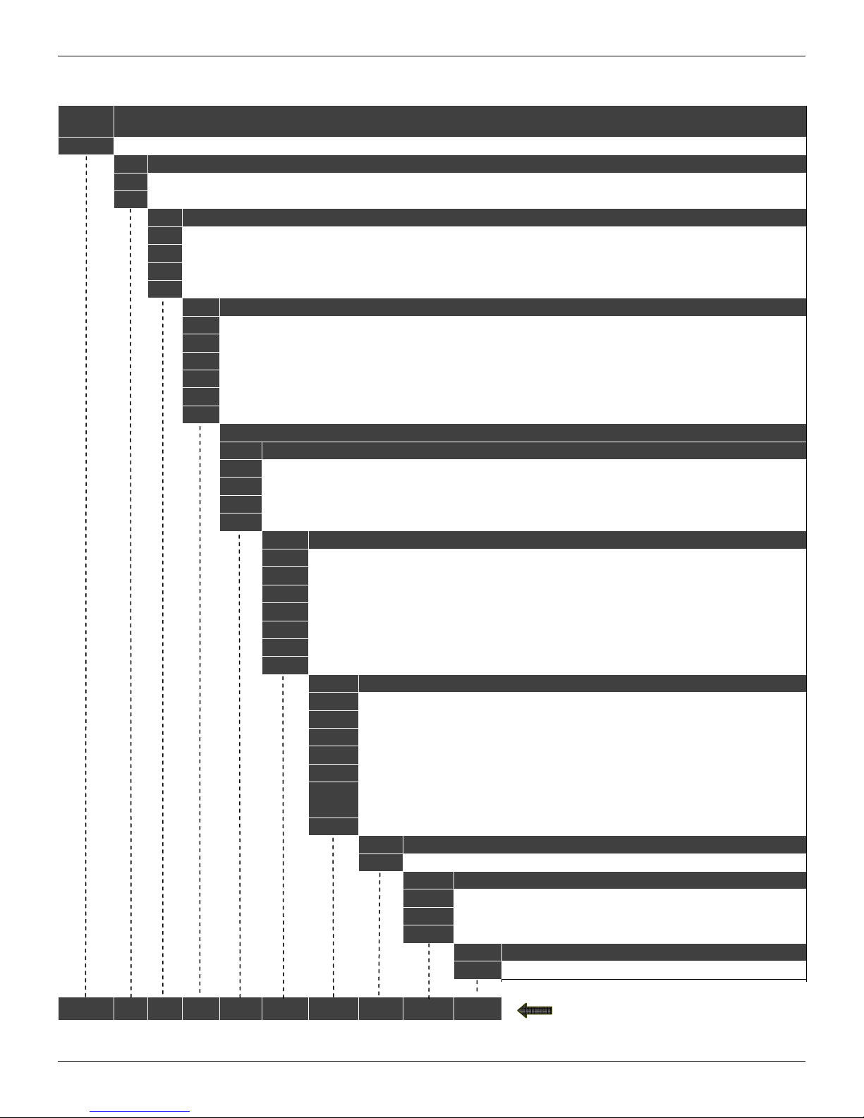
Ordering Code
MODEL
IF302 TRIPLE CHANNEL CURRENT TO FOUNDATION FIELDBUS CONVERTER
COD. Local Indicator
0 Without indicator
1 With indicator
COD. Mounting Bracket
0 Without Bracket
1 Carbon Steel Accessories: Carbon Steel
2 316 Stainless Steel. Accessories: AI316
7 Carbon Steel. Accessories: AI316
COD. Electrical Connections
0 1/2" - 14 NPT
1 1/2" - 14 NPT X 3/4 NPT (AI 316) - with adapter
2 1/2" - 14 NPT X 3/4 BSP (AI 316) - with adapter
3 1/2" - 14 NPT X 1/2 BSP (AI 316) - with adapter
A M20 X 1.5
B PG 13.5 DIN
SPECIAL OPTIONS
COD. Housing
H0 Aluminum (IP/TYPE)
H1 316 Stainless Steel (IP/TYPE)
H2 Aluminum for saline atmosphere (IPW/TYPE X)
H3 316 Stainless Steel for saline atmosphere (IPW/TYPE X)
COD. Identification Plate
I1 FM: XP, IS, NI, DI
I3 CSA: XP, IS, NI, DI
I4 EXAM (DMT): Ex-ia; NEMKO: Ex-d
I5 CEPEL: Ex-d, Ex-ia
I6 Without Certification
IE NEPSI: Ex-ia
IJ NEMKO - Ex-d
COD. Painting
P0 Gray Munsell N 6,5 Polyester
P3 Black Polyester
P4 White Epoxi
P5 Yellow Polyester
P8 Without Painting
P9 Safety Blue Epoxy - Electrostatic Painting
PC Safety Blue Polyester - Electrostatic Painting
PG Safety Orange Epoxi Paint - Electrostatic Painting
COD. Input Signal
T0 3 output, 4 to 20 mA
COD. Tag Plate
J0 With tag
J1 Blank
J2 According to user’s notes
COD. Special
ZZ See Notes
IF302 1 1 0 * * * * * *
* Leave it blank for no optional items.
TYPICAL MODEL
5.2
Page 35

Crrgpfkz"C"
CERTIFICATIONS INFORMATION
Gwtqrgcp"Fktgevkxg"Kphqtocvkqp"
Consult www.smar.com for the EC declarations of conformity for all applicable European directives
and certificates.
ATEX Directive (94/9/EC) – “Electrical equipment and protective system intended for use in
potential explosive atmospheres”
The EC-Type Examination Certificate had been released by Nemko AS (CE0470) and/or DEKRA
EXAM GmbH (CE0158), according to European Standards.
The certification body for Production Quality Assurance Notification (QAN) and IECEx Quality
Assessment Report (QAR) is Nemko AS (CE0470).
LVD Directive 2006/95/EC – “Electrical Equipment designed for use within certain voltage
limits”
According the LVD directive Annex II, electrical equipment for use in an explosive atmosphere is
outside the scope of this directive.
According to IEC standard: IEC 61010-1:2010 - Safety requirements for electrical equipment for
measurement, control, and laboratory use - Part 1: General requirements.
"
EMC Directive 2004/108/EC - “Electromagnetic Compatibility”
The equipment is in compliance with the directive and EMC test was performed according to IEC
standards: IEC61326-1:2005 and IEC61326-2-3:2006.
To comply with the EMC directive the installation must follow these special conditions:
Use shielded, twisted-pair cable for powering the instrument and signal wiring.
Keep the shield insulated at the instrument side, connecting the other one to the ground.
Jc|ctfqwu"Nqecvkqpu"Igpgtcn"Kphqtocvkqp"
Ex Standards:
IEC 60079-0 General Requirements
IEC 60079-1 Flameproof Enclosures “d”
IEC 60079-11 Intrinsic Safety “i”
IEC 60079-26 Equipment with equipment protection level (EPL) Ga
IEC 60529 Classification of degrees of protection provided by enclosures (IP Code)
Customer responsibility:
IEC 60079-10 Classification of Hazardous Areas
IEC 60079-14 Electrical installation design, selection and erection
IEC 60079-17 Electrical Installations, Inspections and Maintenance
Warning:
Explosions could result in death or serious injury, besides financial damage.
Installation of this instrument in an explosive environment must be in accordance with the national
standards and according to the local environmental protection method. Before proceeding with the
installation match the certificate parameters according to the environmental classification.
General Notes:
Maintenance and Repair
The instrument modification or replaced parts supplied by any other supplier than authorized
representative of Smar Equipamentos Industriais Ltda is prohibited and will void the Certification.
Marking Label
Once a device labeled with multiple approval types is installed, do not reinstall it using any other
approval types. Scratch off or mark unused approval types on the approval label.
For Ex-i protection application
- Connect the instrument to a proper intrinsically safe barrier.
C03
Page 36

KH524"⁄"Qrgtcvkqp"cpf"Ockpvgpcpeg"Kpuvtwevkqp"Ocpwcn"
- Check the intrinsically safe parameters involving the barrier, equipment including the cable and
connections.
- Associated apparatus ground bus shall be insulated from panels and mounting enclosures.
- When using shielded cable, isolate the not grounded cable end.
- Cable capacitance and inductance plus Ci and Li must be smaller than Co and Lo of the Associated
Apparatus.
For Ex-d protection application
- Only use Explosion Proof/Flameproof certified Plugs, Adapters and Cable glands.
- In an Explosion-Proof/Flame-Proof installation, do not remove the instrument housing covers when
powered on.
- Electrical Connection
In Explosion-Proof installations the cable entries must be connected through conduit with sealed
unit or closed using metal cable gland or closed using metal blanking plug, all with at least IP66
and Ex-d certification. For enclosure with saline environment protection (W) and ingress protection
(IP) applications, all NPT thread parts must apply a proper water-proof sealant (a non-hardening
silicone group sealant is recommended).
For Ex-d and Ex-i protection application
- The transmitter has a double protection. In this case the transmitter shall be fitted with appropriate
certified cable entries Ex-d and the electric circuit supplied by a certified diode safety barrier as
specified for the protection Ex-ia.
Environmental Protection
- Enclosure Types (Type X): Supplementary letter X meaning special condition defined as default by
Smar the following: Saline Environment approved - salt spray exposed for 200 hours at 35ºC. (Ref:
NEMA 250).
- Ingress protection (IP W): Supplementary letter W meaning special condition defined as default by
Smar the following: Saline Environment approved - salt spray exposed for 200 hours at 35ºC. (Ref:
IEC60529).
- Ingress protection (IP x8): Second numeral meaning continuous immersion in water under special
condition defined as default by Smar the following: 1 Bar pressure during 24hours. (Ref: IEC60529).
Jc|ctfqwu"Nqecvkqpu"Crrtqxcnu"
CSA (Canadian Standards Association)
Class 2258 02 – Process Control Equipment – For Hazardous Locations (CSA1002882)
Class I, Division 1, Groups B, C and D
Class II, Division 1, Groups E, F and G
Class III, Division 1
Class I, Division 2, Groups A, B, C and D
Class II, Division 2, Groups E, F and G
Class III
CLASS 2258 03 - PROCESS CONTROL EQUIPMENT – Intrinsically Safe and Non-Incendive Systems - For Hazardous
Locations (CSA 1002882)
Class I, Division 2, Groups A, B, C and D
Model IF302 Converter; supply 12-42V dc, 4-20mA; Enclosure Type 4/4X; non-incendive with Fieldbus/FNICO Entity
parameters
@ Terminals + and - :
Vmax =24V, Imax =570 mA, Pmax = 9.98 W, Ci = 5 nF, Li = 12uH;
@ Terminals 1 - 4:
Vmax =30V, Imax =110mA, Ci = 5 nF, Li = 12uH;
when connected through CSA Certified Safety Barriers as per SMAR Installation drawing 102A0558; Temp. Code T3C.
Class 2258 04 – Process Control Equipment – Intrinsically Safe Entity – For Hazardous Locations (CSA 1002882)
Class I, Division 1, Groups A, B, C and D
Class II, Division 1, Groups E, F and G
Class III, Division 1
FISCO Field Device
Model IF302 Converter; supply 12-42V dc, 4-20mA; Enclosure Type 4/4X; Intrinsically safe with Fieldbus/FISCO Entity
parameters
C04"
Page 37

Egtvkhkecvkqpu"Kphqtocvkqp"
@ Terminals + and -:
Vmax = 24 V, Imax = 380 mA, Pi = 5.32 W, Ci = 5 nF, Li = 12 uH;
@ Terminals 1 – 4: Vmax = 30 V, Imax = 110 mA, Ci = 5nF, Li = 12 u H;
when connected through CSA Certified Safety Barriers as per Smar Installation Drawing 102A0558; Code T3C.
Note: Only models with stainless steel external fittings are Certified as Type 4X.
Special conditions for safe use:
Temperature Class T3C
Maximum Ambient Temperature: 40ºC (-20 to 40 ºC)
FM Approvals (Factory Mutual)
Intrinsic Safety (FM 0D7A9.AX)
IS Class I, Division 1, Groups A, B, C and D
IS Class II, Division 1, Groups E, F and G
IS Class III, Division 1
Explosion Proof (FM 0D7A9.AX)
XP Class I, Division 1, Groups A, B, C and D
Dust Ignition Proof (FM 0D7A9.AX)
DIP Class II, Division 1, Groups E, F and G
DIP Class III, Division 1
Non Incendive (FM 0D7A9.AX)
NI Class I, Division 2, Groups A, B, C and D
Environmental Protection (FM 0D7A9.AX)
Option: Type 4X/6/6P or Type 4/6/6P
Special conditions for safe use:
Entity Parameters Fieldbus Power Supply Input (report 3015629):
Vmax = 24 Vdc, Imax = 250 mA, Pi = 1.2 W, Ci = 5 nF, Li = 12 uH
Vmax = 16 Vdc, Imax = 250 mA, Pi = 2 W, Ci = 5 nF, Li = 12 uH
4-20 mA Current Loop:
Vmax = 30 Vdc, Imax = 110 mA, Pi = 0,825 W, Ci = 5 nF, Li = 12 uH
Temperature Class T4
Maximum Ambient Temperature: 60ºC (-20 to 60 ºC)
NEMKO (Norges Elektriske MaterielKontroll)
Explosion Proof (NEMKO 13 ATEX 1570X)
Group II, Category 2 G, Ex d, Group IIC, Temperature Class T6, EPL Gb
Ambient Temperature: -20 ºC to +60 ºC
Environmental Protection (NEMKO 03ATEX1570X)
Options: IP66/68W or IP66/68
Special conditions for safe use:
Repairs of the flameproof joints must be made in compliance with the structural specifications provided by the manufacturer.
Repairs must not be made on the basis of values specified in tables 1 and 2 of EN/IEC 60079-1.
The Essential Health and Safety Requirements are assured by compliance with:
EN 60079-0:2012 General Requirements
EN 60079-1:2007 Flameproof Enclosures “d”
EXAM (BBG Prüf - und Zertifizier GmbH)
Intrinsic Safety (DMT 00 ATEX E 064)
Group I, Category M2, Ex ia, Group I, EPL Mb
Group II, Category 2 G, Ex ia, Group IIC, Temperature Class T4/T5/T6, EPL Gb
C05"
Page 38

KH524"⁄"Qrgtcvkqp"cpf"Ockpvgpcpeg"Kpuvtwevkqp"Ocpwcn"
FISCO Field Device
Supply circuit for the connection to an intrinsically safe FISCO fieldbus-circuit:
Ui = 24Vdc, Ii = 380 mA, Pi = 5.32 W, Ci ≤ 5 nF, Li = neg
Parameters of the supply circuit comply with FISCO model according to Annex G EN 60079-11:2012, replacing EN 60079-27:
2008.
Input-signal-circuits:
three 0-20 mA or 4-20 mA signal inputs with common ground
Input impedance (load impedance) Ri 100
Effective internal capacitance Ci negligible
Effective internal inductance Li negligible
Safety relevant maximum values for certified intrinsically safe 0-20 mA or 4-20 mA signal circuits as a function of ambient
temperature and temperature class
Max. Ambient
temperature Ta
60ºC T4 28 V 93 mA 750 mW
50ºC T5 28 V 93 mA 750 mW
40ºC T6 28 V 93 mA 570 mW
The signal inputs are safely galvanically separated from the fieldbus circuit.
Ambient Temperature: -40ºC ≤ Ta ≤ +60ºC
The Essential Health and Safety Requirements are assured by compliance with:
EN 60079-0:2012 + A11:2013 General Requirements
EN 60079-11:2012 Intrinsic Safety “i”
CEPEL (Centro de Pesquisa de Energia Elétrica)
Intrinsic Safety (CEPEL 97.0020X)
Ex ia, Group IIC, Temperature Class T4/T5, EPL Ga
FISCO Field Device
Entity Parameters:
Pi = 5.32 W, Ui = 30V, Ii = 380mA, Ci = 5.0nF, Li = Neg
Ambient Temperature:
-20 to 65ºC T4
-20 to 50ºC T5
Explosion Proof (CEPEL 97.0090)
Ex d, Group IIC, Temperature Class T6, EPL Gb
Maximum Ambient Temperature: 40ºC (-20 to 40 ºC)
Environmental Protection (CEPEL 97.0020X AND CEPEL 97.0090)
Options: IP66/68W or IP66/68
Special conditions for safe use:
The certificate number ends with the letter "X" to indicate that for the version of Current to FIELDBUS Converter model IF302
equipped with housing made of aluminum alloy, only can be installed in "Zone 0" if is excluded the risk of occurs impact or friction
between the housing and iron/steel itens.
The Essential Health and Safety Requirements are assured by compliance with:
ABNT NBR IEC 60079-0:2008 General Requirements
ABNT NBR IEC 60079-1:2009 Flameproof Enclosures “d”
ABNT NBR IEC 60079-11:2009 Intrinsic Safety “i”
ABNT NBR IEC 60079-26:2008 Equipment with equipment protection level (EPL) Ga
IEC 60079-27:2008 Fieldbus intrinsically safe concept (FISCO)
ABNT NBR IEC 60529:2009 Classification of degrees of protection provided by enclosures (IP Code)
Temperature
Class
Voltage
DC Ui
Current Ii Power Pi
C06"
Page 39
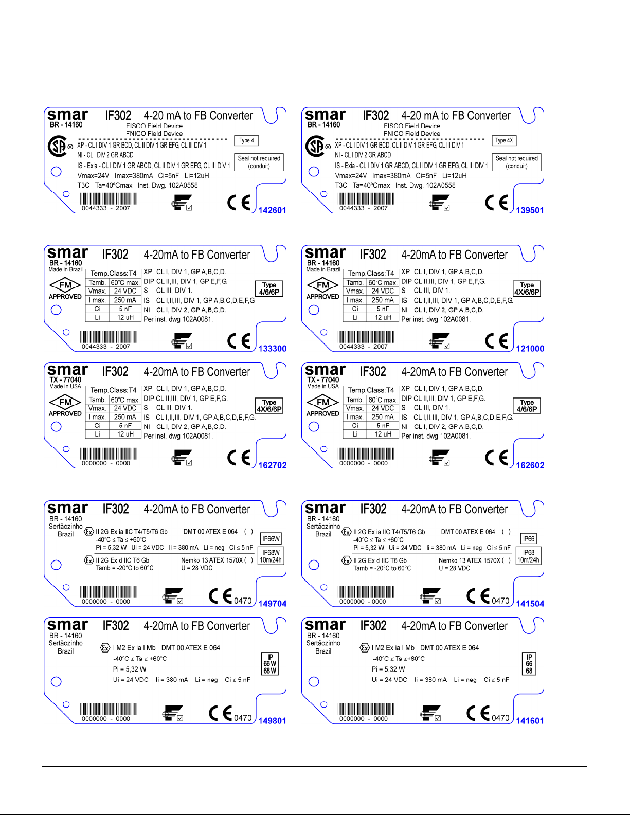
Kfgpvkhkecvkqp"Rncvg""
CSA (Canadian Standards Association)
Egtvkhkecvkqpu"Kphqtocvkqp"
FM Approvals (Factory Mutual)
NEMKO (Norges Elektriske MaterielKontroll) / EXAM (BBG Prüf - und Zertifizier GmbH)
C07"
Page 40
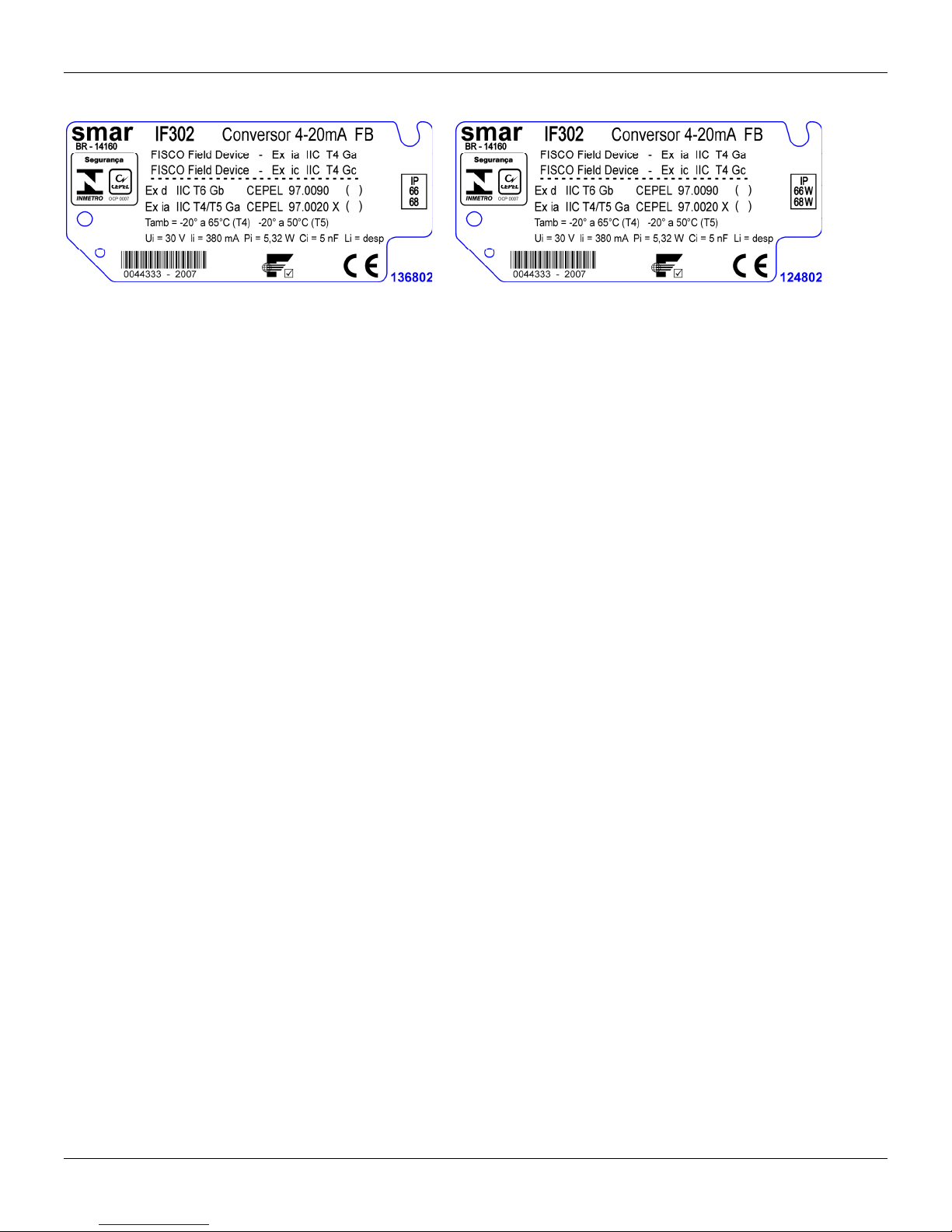
KH524"⁄"Qrgtcvkqp"cpf"Ockpvgpcpeg"Kpuvtwevkqp"Ocpwcn"
CEPEL (Centro de Pesquisa de Energia Elétrica)
C08"
Page 41
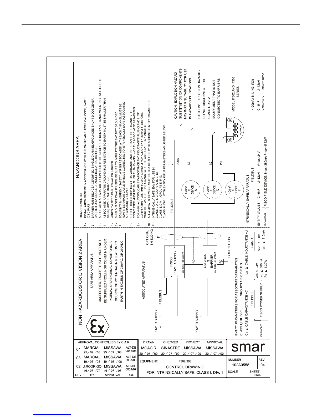
Eqpvtqn"Ftcykpi"
Canadian Standards Association (CSA)
Egtvkhkecvkqpu"Kphqtocvkqp"
C09
Page 42
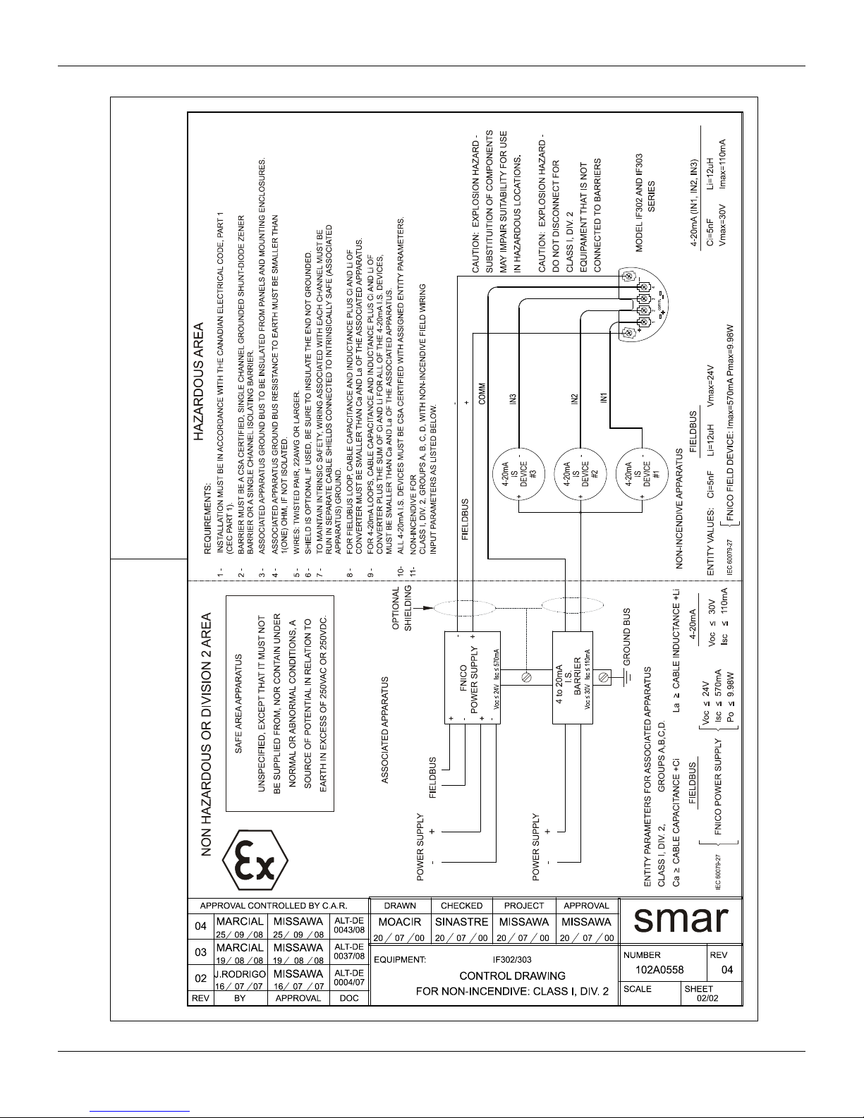
KH524"⁄"Qrgtcvkqp"cpf"Ockpvgpcpeg"Kpuvtwevkqp"Ocpwcn"
C0:"
Page 43
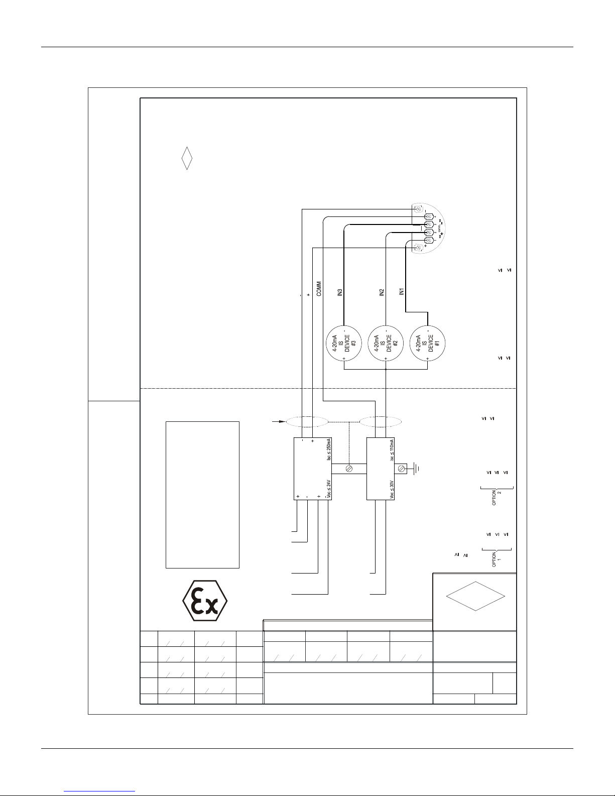
Factory Mutual (FM)
Egtvkhkecvkqpu"Kphqtocvkqp"
APPROVAL.
PREVIOUS MANUFACTURER
BE SUBSTITUTED WITHOUT
COMPONENTS CAN NOT
110 mA
30V
Imax
4-20mA
Vmax
Ci=5nF Li=12uH
TRANSMITTER SPECIFICATION MUST BE IN ACCORDANCE TO FM
REQUIREMENTS:
(ANSI/NFPA 70) AND ANSI/ISA-RP12.6
APPROVAL LISTING.
1 - INSTALLATION MUST BE IN ACCORDANCE WITH THE NATIONAL ELECTRICAL CODE
2 -
SAFE AREA APPARATUS
UNSPECIFIED, EXCEPT THAT IT MUST NOT
BE SUPPLIED FROM, NOR CONTAIN UNDER
NON HAZARDOUS OR DIVISION 2 AREA HAZARDOUS AREA
MARCIAL
7
20
MARCIAL
6
16
MOACIR
5
07
MOACIR
4
REV.
DESIGN AREA
10 08 20
07 07 16
CASSIOLATO
05 03 07
CASSIOLATO
MISSAWA
MISSAWA
08
AND MOUNTING ENCLOSURES.
3 - ASSOCIATED APPARATUS GROUND BUS TO BE INSULATED FROM PANELS
NORMAL OR ABNORMAL CONDITIONS, A
10 08
07 07
05 03
250mA
24V
SHIELD IS OPTIONAL IF USED, BE SURE TO INSULATE THE END NOT
WIRES: TWISTED PAIR, 22AWG OR LARGER.
SMALLER THAN 1(ONE) OHM.
4 - ASSOCIATED APPARATUS GROUND BUS RESISTANCE TO EARTH MUST BE
SOURCE OF POTENTIAL IN RELATION TO
EARTH IN EXCESS OF 250VAC OR 250VDC.
5 - OBSERVE TRANSMITTER POWER SUPPLY LOAD CURVE.
6 -
ASSOCIATED APPARATUS
GROUNDED.
SMALLER THAN Ca AND La OF THE ASSOCIATED APPARATUS.
FIELDBUS
Imax
Ci=5nF Li=12uH
Vmax
110 mAIsc
30V
Voc
2W
250mA
16V
Po
Isc
Voc
1,2W
24V
250mA
Po
Isc
Voc
CLASS I,II,III DIV.1, GROUPS A,B,C,D,E,F & G
MODELS IF302 AND IF303 - SERIES
7 -
8 - CABLE CAPACITANCE AND INDUTANCE PLUS Ci AND Li MUST BE
FIELDBUS
OPTIONAL
SHIELDING
GROUND BUS
I.S.
BARRIER
FIELDBUS
FIELDBUS
I.S.
BARRIER
4 to 20mA
CLASS I,II,III DIV.1
ENTITY PARAMETERS FOR ASSOCIATED APPARATUS
ENTITY VALUES:
4-20mA
FIELDBUS
Ca CABLE CAPACITANCE +5nF
La CABLE INDUCTANCE +12uh
GROUPS A,B,C,D,E,F & G
+-
-+
POWER SUPPLY
ALT DE
DRAWING DESIGN VERIFIED APPROVED
0049/08
MELONI
ALT DE
0004/07
28
ALT DE
CUSTOMER:
0043/03
EQUIPMENT: IF302/303
ALT DE
0015/00
0002000208
APPROVAL CONTROLLED BY C.A.R.
M.MISSAWA
03
95 28
03
CONTROL DRAWING
95 28
POWER SUPPLY
PELUSOSINASTRE
03
95 28
03
95
FM
APPROVED
smar
O.S.
DRAWING N.
102A0081
: SH.
REV
07
01/01APPROVED
C0;"
Page 44

KH524"⁄"Qrgtcvkqp"cpf"Ockpvgpcpeg"Kpuvtwevkqp"Ocpwcn"
C032"
Page 45
Appendix B
Model: IF302 ( ) IF303 ( )
Serial Number: _______________________________________________________________________________________________________
TAG: _______________________________________________________________________________________________________
How many
channels are
used in IF?
Configuration: Magnetic Tool ( ) PC ( ) Software: _____________ Version: _______________________
Type/Model/Manufacturer of device
connected to the channel 1:
Type/Model/Manufacturer of device
connected to the channel
Type/Model/Manufacturer of device
connected to the channel
Hazardous Area
Classification:
( ) No
More details: ________________________________________________________________________________________
Types of Interference
presents in the area:
Ambient
Temperature:
______________________________________________________________________________________________________________________
1 ( ) 2 ( ) 3 ( )
_______________________________________________________________________________________
_______________________________________________________________________________________
_
_______________________________________________________________________________________
2:
3:
( ) Yes, please specify: _______________________________________________________________________________
Without interference ( ) Temperature ( ) Vibration ( ) Others: _____________________________________
From __________ºC up to __________ºC
SRF – Service Request Form
Converter from 4-20mA to Fieldbus
GENERAL DATA
INSTALLATION DATA
PROCESS DATA
OCCURRENCE DESCRIPTION
______________________________________________________________________________________________________________________
______________________________________________________________________________________________________________________
______________________________________________________________________________________________________________________
Adjustment ( ) Cleaning ( ) Preventive Maintenance ( ) Update / Up-grade ( )
Other: ___________________________________________________________ _____________________________________________________
Company: _____________________________________________________________________________________________________________
Contact: _______________________________________________________________________________________________________________
Title: _________________________________________________________________________________________________________________
Section: ______________________________________________________________________________________________________________
Phone: _________ _________________________ _________ _________________________ Extension: ___________________________
E-mail: ________________________________________________________________________ Date: ______/ ______/ __________________
For warranty or non-warranty repair, please contact your representative.
Further information about address and contacts can be found on www.smar.com/contactus.asp.
SERVICE SUGGESTION
USER INFORMATION
B.1
Page 46

IF302 – Operation, Maintenance and Instructions Manual
Returning Materials
Should it become necessary to return the converter to SMAR, simply contact your loc al agent or
SMAR office, informing the defective instrument’s serial number, and return it to our factory.
In order to expedite analysis and solution of the problem, the defective item shoul d be returned with
a description of the failure observed, with as many details as possi ble. Other informatio n concer ning
to the instrument operation, such as service and process conditions, is also helpful.
B.2
 Loading...