

Page 1
A
OPERATION, MAINTENANCE
ND INSTRUCTION MANUAL
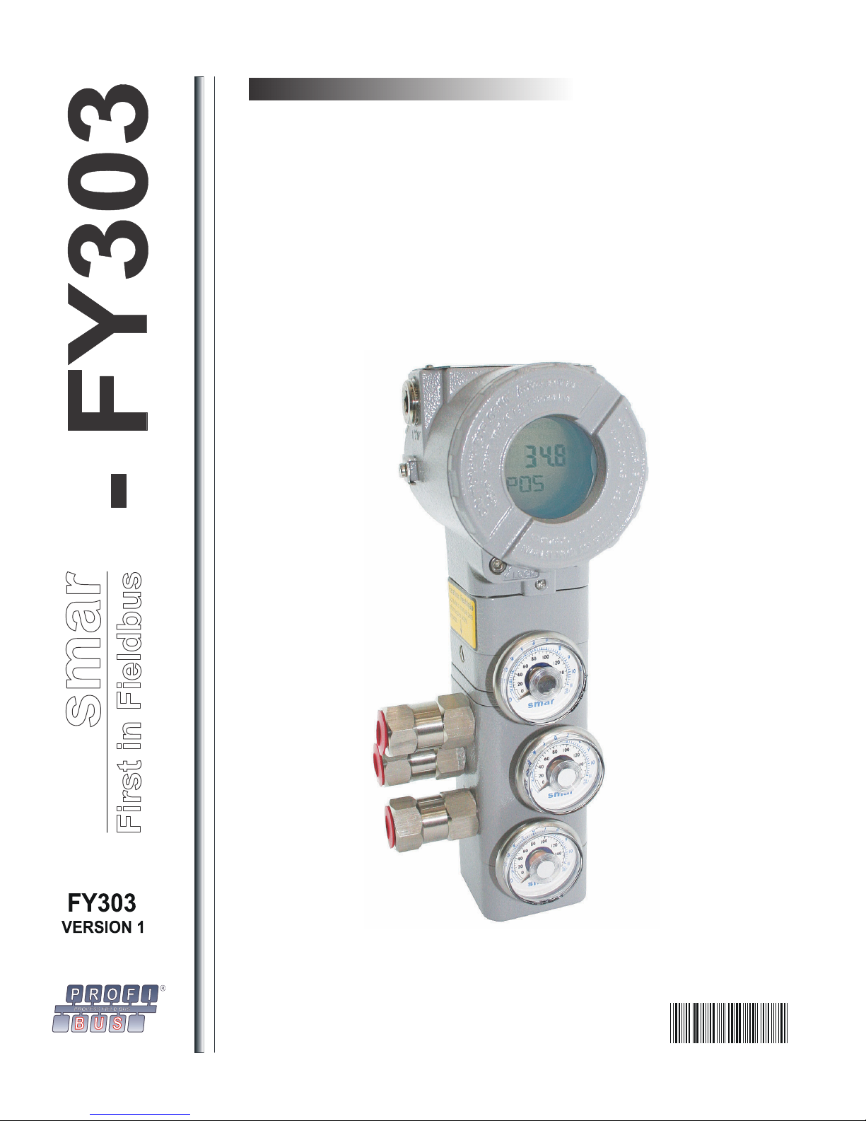
Profibus PA Valve Positioner
JUL / 16
FY303ME
Page 2

smar
Specifications and information are subject to change without notice.
Up-to-date address information is available on our website.
web: www.smar.com/contactus.asp
www.smar.com
Page 3

Kpvtqfwevkqp"
INTRODUCTION
The FY303 is a Profibus PA valve positioner for Single (spring return) or Double acting Linear
motion type control valves e. g. Globe, Gate, Diaphragm, Pinch or Clamp and Rotary motion type
control valves e. g. Ball, Butterfly or Plug with pneumatic type actuators e. g. Diaphragm, Piston,
Vane, or Bellows. It is based on a field-proven piezo flapper and non-contacting Hall-effect position
sensor that provides reliable operation and high performance. The digital technology used in the
FY303 enabled the choice of several types of flow characterizations, an easy interface between the
field and the control room and several interesting features that considerably reduce the installation,
operating and maintenance costs.
The FY303 is part of Smar's complete 303 line of Profibus PA devices.
Some of the advantages of bi-directional digital communications are known from existing smart
transmitter protocols: Higher accuracy, multi-variable access, remote configuration and diagnostics,
and multi-dropping of several devices on a single pair of wires.
The system controls variable sampling, algorithm execution and communication so as to optimize
the usage of the network, not loosing time. Thus, high closed loop performance is achieved.
Using Profibus technology, with its capability to interconnect several devices, very large control
schemes can be constructed. In order too be user friendly the function block concept was
introduced.
The need for implementation of Fieldbus in small as well as large systems was considered when
developing the entire 303 line of Profibus-PA devices. They have common features and can be
configured locally using a magnetic tool, eliminating the need for a configuration tool or console in
many basic applications.
Get the best result of the FY303 by carefully reading these instructions.
NOTE
In case of using Simatic PDM as the configuration and parameterization tool, Smar
recommends that the user does not apply the option "Download to Device". This function
can improperly configure the field device. Smar recommends that user make the use of
the option "Download to PG / PC" and then selecting the Device Menu, use the menus of
the transducer, function and display blocks acting specifically, according to each menu
and method for reading and writing.
WARNING
Throughout the operation of the positioner, including self-setup, do not touch the moving parts of
valve/actuator/positioner assembly as they may unexpectedly move automatically. Make sure to disconnect
supply air before touching any moving parts.
KKK"
Page 4

H[525"/"Qrgtcvkqp."Ockpvgpcpeg"cpf"Kpuvtwevkqpu"Ocpwcn"
r
r
This manual is compatible with version 1XX, where 1 denotes software version and XX software release. The
indication 1.XX means that this manual is compatible with any release of software version 1.
Waiver of responsibility
The contents of this manual abides by the hardware and software used on the current equipment
version. Eventually there may occur divergencies between this manual and the equipment. The
information from this document are periodically reviewed and the necessary or identified corrections
will be included in the following editions. Suggestions for their improvement are welcome.
Warning
For more objectivity and clarity, this manual does not contain all the detailed information on the
product and, in addition, it does not cover every possible mounting, operation or maintenance
cases.
Before installing and utilizing the equipment, check if the model of the acquired equipment complies
with the technical requirements for the application. This checking is the user’s responsibility.
If the user needs more information, or on the event of specific problems not specified or treated in
this manual, the information should be sought from Smar. Furthermore, the user recognizes that the
contents of this manual by no means modify past or present agreements, confirmation or judicial
relationship, in whole or in part.
All of Smar’s obligation result from the purchasing agreement signed between the parties, which
includes the complete and sole valid warranty term. Contractual clauses related to the warranty are
not limited nor extended by virtue of the technical information contained in this manual.
Only qualified personnel are allowed to participate in the activities of mounting, electrical connection,
startup and maintenance of the equipment. Qualified personnel are understood to be the persons
familiar with the mounting, electrical connection, startup and operation of the equipment or othe
similar apparatus that are technically fit for their work. Smar provides specific training to instruct and
qualify such professionals. However, each country must comply with the local safety procedures,
legal provisions and regulations for the mounting and operation of electrical installations, as well as
with the laws and regulations on classified areas, such as intrinsic safety, explosion proof, increased
safety and instrumented safety systems, among others.
The user is responsible for the incorrect or inadequate handling of equipments run with pneumatic
or hydraulic pressure or, still, subject to corrosive, aggressive or combustible products, since thei
utilization may cause severe bodily harm and/or material damages.
The field equipment referred to in this manual, when acquired for classified or hazardous areas, has
its certification void when having its parts replaced or interchanged without functional and approval
tests by Smar or any of Smar authorized dealers, which are the competent companies for certifying
that the equipment in its entirety meets the applicable standards and regulations. The same is true
when converting the equipment of a communication protocol to another. In this case, it is necessary
sending the equipment to Smar or any of its authorized dealer. Moreover, the certificates are
different and the user is responsible for their correct use.
Always respect the instructions provided in the Manual. Smar is not responsible for any losses
and/or damages resulting from the inadequate use of its equipments. It is the user’s responsibility to
know and apply the safety practices in his country.
NOTE
KX"
Page 5

Vcdng"qh"Eqpvgpvu"
TABLE OF CONTENTS
UGEVKQP"3"/"KPUVCNNCVKQP"0000000000000000000000000000000000000000000000000000000000000000000000000000000000000000000000000000000000000000"303
GENERAL ...................................................................................................................................................... 1.1
MOUNTING .................................................................................................................................................... 1.1
ROTARY MOVEMENT ................................................................................................................................... 1.1
PNEUMATIC CONNECTIONS ....................................................................................................................... 1.2
ELECTRONIC HOUSING ROTATING ........................................................................................................... 1.6
ELECTRIC WIRING ........................................................................................................................................ 1.6
TOPOLOGY AND NETWORK CONFIGURATION ........................................................................................ 1.7
INTRINSIC SAFETY BARRIER ...................................................................................................................... 1.8
JUMPER CONFIGURATION .......................................................................................................................... 1.8
POWER SUPPLY ........................................................................................................................................... 1.9
AIR SUPPLY REQUIREMENTS ..................................................................................................................... 1.9
RECOMMENDATIONS FOR AN INSTRUMENT AIR SYSTEM ..................................................................... 1.9
ROTARY AND LINEAR MAGNET ................................................................................................................ 1.10
MAGNET
REMOTE
UGEVKQP"4"/"QRGTCVKQP"000000000000000000000000000000000000000000000000000000000000000000000000000000000000000000000000000000000000000000000"403
FUNCTIONAL DESCRIPTION - OUTPUT MODULE ..................................................................................... 2.1
FUNCTIONAL DESCRIPTION-ELECTRONICS ............................................................................................ 2.2
INTRODUCTION TO FIELDBUS APPLICATION ........................................................................................... 2.4
FUNCTION BLOCKS ...................................................................................................................................... 2.4
TRANSDUCER BLOCKS ............................................................................................................................... 2.4
PHYSICAL BLOCK ......................................................................................................................................... 2.4
THE LOCAL INDICATOR ............................................................................................................................... 2.4
UGEVKQP"5"/"EQPHKIWTCVKQP"000000000000000000000000000000000000000000000000000000000000000000000000000000000000000000000000000000000000"503
TRANSDUCER BLOCK ................................................................................................................................. 3.1
HOW TO CONFIGURE A TRANSDUCER BLOCK ........................................................................................ 3.1
FUNCTIONAL DIAGRAM OF THE POSITIONER TRANSDUCER BLOCK ................................................... 3.2
TRANSDUCER BLOCK STANDARD PARAMETER DESCRIPTIONS ......................................................... 3.3
TRANSDUCER BLOCK SPECIFIC PARAMETER DESCRIPTIONS ............................................................. 3.5
TRANSDUCER BLOCK PARAMETER ATTRIBUTE TABLE ......................................................................... 3.7
TRANSDUCER BLOCK VIEW OBJECT TABLE ............................................................................................ 3.9
FY303 CYCLICAL CONFIGURATION ......................................................................................................... 3.12
HOW TO CONFIGURE THE ANALOG OUTPUT BLOCK ............................................................................ 3.17
POSITION CALIBRATION ........................................................................................................................... 3.20
TEMPERATURE CALIBRATION ................................................................................................................. 3.23
SELF-CALIBRATION ................................................................................................................................... 3.24
DIAGNOSIS .................................................................................................................................................. 3.25
TRANSDUCER DISPLAY - CONFIGURATION ........................................................................................... 3.26
DISPLAY TRANSDUCER BLOCK ............................................................................................................... 3.27
DEFINITION OF PARAMETERS AND VALUES .......................................................................................... 3.28
CALIBRATING USING LOCAL ADJUSTMENT ........................................................................................... 3.30
SELF-CALIBRATION USING LOCAL ADJUSTMENT ................................................................................. 3.34
HALL'S OFFSET COMPENSATION WITHOUT MAGNET PART ................................................................ 3.34
TEMPERATURE COMPENSATION ............................................................................................................ 3.35
PRESSURE SENSORS VERSION (K1 OPTION) ........................................................................................ 3.36
UGEVKQP"6"/"OCKPVGPCPEG"RTQEGFWTGU"0000000000000000000000000000000000000000000000000000000000000000000000000000000000000"603
GENERAL ...................................................................................................................................................... 4.1
DISASSEMBLY PROCEDURE ...................................................................................................................... 4.2
REASSEMBLY PROCEDURE ....................................................................................................................... 4.3
RESTRICTION CLEANING PROCEDURE .................................................................................................... 4.3
CHANGE OF THE FILTER ELEMENTS ......................................................................................................... 4.4
CENTRALIZER DEVICE .............................................................................................................. 1.10
HALL SENSOR ............................................................................................................................ 1.10
X"
Page 6

H[525"/"Qrgtcvkqp."Ockpvgpcpeg"cpf"Kpuvtwevkqpu"Ocpwcn"
ELECTRONIC CIRCUIT ................................................................................................................................. 4.4
INTERCHANGEABILITY ................................................................................................................................ 4.5
PACKAGE CONTENT .................................................................................................................................... 4.5
EXPLODED
VIEW .......................................................................................................................................... 4.6
SPARE PARTS LIST ...................................................................................................................................... 4.7
DETAILED
CODE WHEN ORDERING OF SPARE PARTS ........................................................................... 4.9
UGEVKQP"7"/"VGEJPKECN"EJCTCEVGTKUVKEU"0000000000000000000000000000000000000000000000000000000000000000000000000000000000"703
FUNCTIONAL SPECIFICATIONS .................................................................................................................. 5.1
PERFORMANCE SPECIFICATIONS ............................................................................................................. 5.2
PHYSICAL SPECIFICATIONS ....................................................................................................................... 5.2
ORDERING CODE ......................................................................................................................................... 5.3
CRRGPFKZ"C"⁄"EGTVKHKECVKQPU"KPHQTOCVKQP"000000000000000000000000000000000000000000000000000000000000000000000000000000"C03
EUROPEAN DIRECTIVE INFORMATION ..................................................................................................... A.1
HAZARDOUS
HAZARDOUS
CSA (CANADIAN STANDARDS ASSOCIATION) ......................................................................................................... A.2
FM
APPROVALS (FACTORY MUTUAL)....................................................................................................................... A.2
NEMKO
EXAM
(BBG PRÜF - UND ZERTIFIZIER GMBH) .......................................................................................................... A.3
CEPEL
LOCATIONS GENERAL INFORMATION ............................................................................... A.1
LOCATIONS APPROVALS..................................................................................................... A.2
(NORGES ELEKTRISKE MATERIELKONTROLL) ......................................................................................... A.3
(CENTRO DE PESQUISA DE ENERGIA ELÉTRICA) ...................................................................................... A.3
IDENTIFICATION PLATE ............................................................................................................................... A.5
CONTROL
DRAWING .................................................................................................................................... A.7
CRRGPFKZ"D"⁄"UTH"⁄"UGTXKEG"TGSWGUV"HQTO"00000000000000000000000000000000000000000000000000000000000000000000000000000"D03
RETURNING MATERIALS ............................................................................................................................. B.2
CRRGPFKZ"E"⁄"UOCT"YCTTCPV["EGTVKHKECVG"00000000000000000000000000000000000000000000000000000000000000000000000000000"E03
CRRGPFKZ"DH["00000000000000000000000000000000000000000000000000000000000000000000000000000000000000000000000000000000000000000000000000000000000000000"3
XK"
Page 7
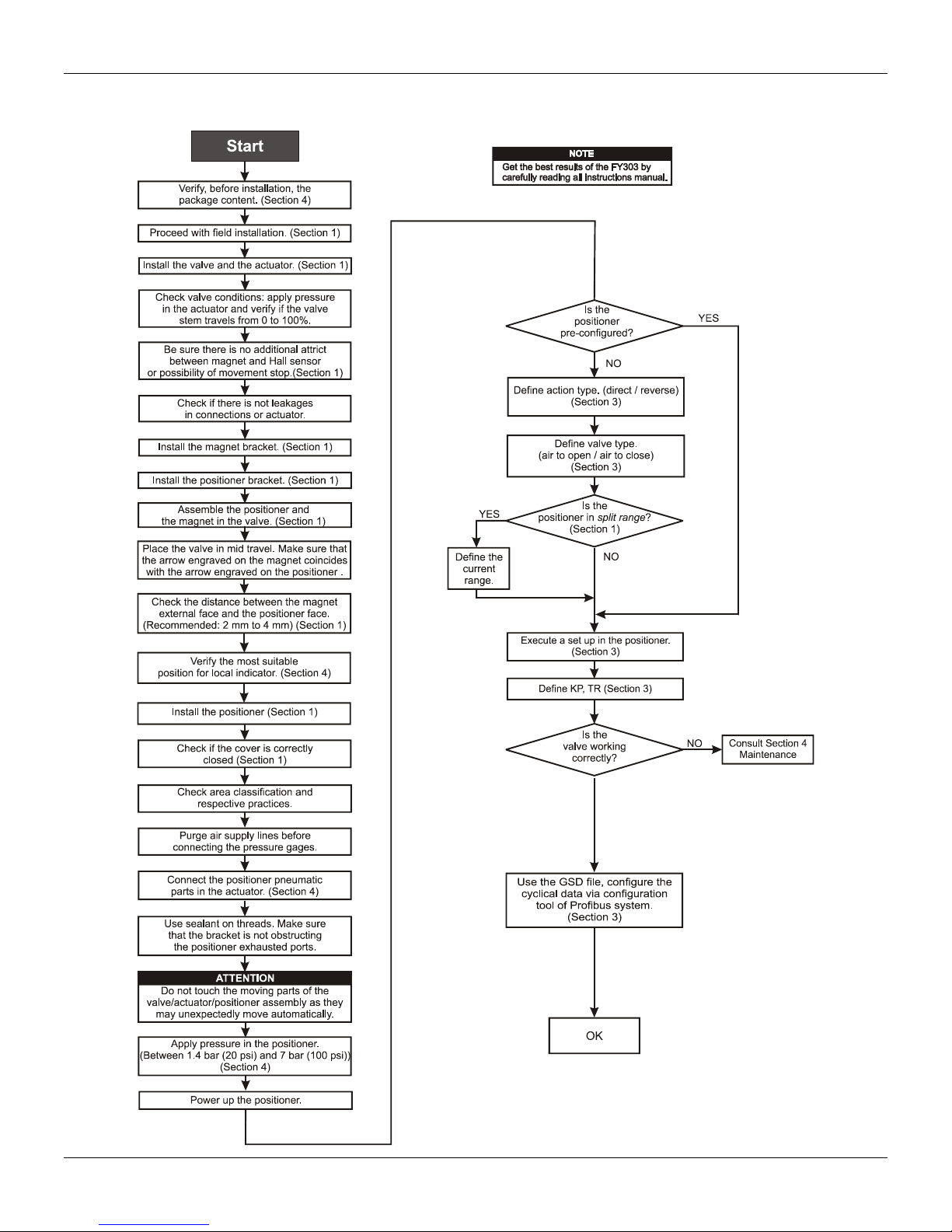
Kpuvcnncvkqp"Hnqyejctv"
Kpuvcnncvkqp"Hnqyejctv"
XKK"
Page 8

H[525"/"Qrgtcvkqp."Ockpvgpcpeg"cpf"Kpuvtwevkqpu"Ocpwcn"
XKKK"
Page 9

Section 1
General
Mounting
Rotary Movement
INSTALLATION
The installation carried out in hazardous areas should follow the recommendations of the IEC60079-14 standard.
The overall accuracy of measurement and control depends on several variables. Although the
converter has an outstanding performance, proper installation is essential, in order to maximize its
performance.
Among all factors, which may affect converter accuracy environmental conditions are the most
difficult to control. There are, however, ways to reduce the effects of temperature, humidity and
vibration.
The FY303 has a built-in temperatur e sensor to compensate for temperature variations. At the field ,
this feature minimizes the temperature variation effect.
Locating the positioner in areas protected from extreme environmental changes can minimize
temperature fluctuation effects.
In warm environments, the positioner should be installed to avoid, as much as possible, direct
exposure to the sun. Installation close to lines and vessels subjected to high temperatures shou ld
also be avoided.
Use of sunshades or heat shields to protect the positioner from external heat sources should be
considered, if necessary.
Humidity is fatal to electronic circuits. In areas subjected to high relative humidity, the O-rings for the
electronics cover must be correctly placed. Removal of the electronics cover in the fiel d should be
reduced to the minimum necessary, since each time it is removed; the circuits are exposed to
humidity. The electronic circuit is protected by a humidity proof coating, but frequ ent exposures to
humidity may affect the provided protection. It is also important to keep the covers tightened in
place. Every time they are removed, the threads ar e exposed to corrosion, since painting cannot
protect these parts. Code approved sealing methods on conduit e ntering the positioner should be
employed.
Although the positioner is virtually insensitiv e to vibration, installation close to pumps, turbines or
other vibrating equipment should be avoided.
The mounting of positioner FY303 will depend on actuator type, single (spring return) action or
double action and on actuator movement, if it is linear or rotary. Two supports are required for
mounting, one for the magnet and the other for the positioner itself. Smar may suppl y them both
since they are specified in the order code.
Install the magnet on the valve stem using the magnet support (See Figure 1.2).
Install the positioner support on the actuator. The actuator should be in accordance with standar d
VDI/VDE 5845, all you have to do is tighten the f our screws with the lock washers on the standard
support.
For special supports, refer to specify instructions. After installing the support on the actuator, it is
possible to mount the positioner FY303 on the support by means of the four screws with lock
washers.
Make sure that the arrow engraved on the magnet coincides with the arrow engraved on the
positioner when the valve is in mid travel.
If the installation of the positioner or magnet should be altered, or if there should be any other
modification, the positioner will require a recalibration.
As to the type of valve action, refer to paragraph "Pneumatic Connections".
NOTE
1.1
Page 10

FY303 - Operation, Maintenance and Instructions Manual
Linear Movement
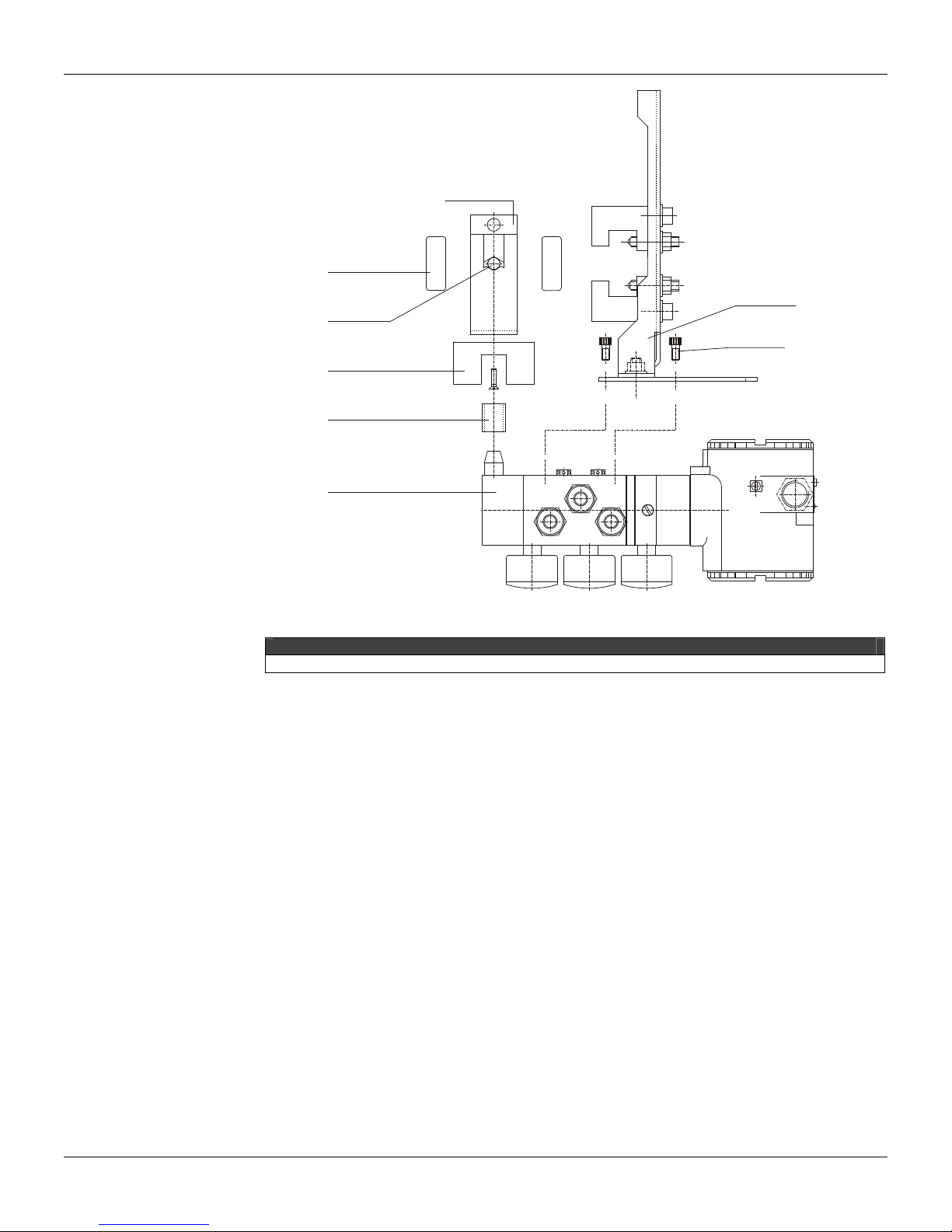
Install the magnet on the valve stem using the magnet support (See Figure 1.3).
Install the positioner support on the actuator. The actuator support may be secured in place as per
standard NAMUR/IEC 536-4 or in accordance with user specified boring. Install the positioner on the
support and tighten the four screws in the threaded bores located on the side opposite to the
pressure gages (See Figure 1.3). Use lock washers in order to prevent screw slackening.
Make sure that the support is not obstructing the exhaustion outlets.
Make sure that arrow engraved on the magnet coincides with the arrow engraved on the positione r when the
valve is in mid travel. The magnet mounting in relation to the hall sensor:
1. Must not have attrition between the internal magnet face and the hall sensor salience during the travel
(rotary or linear), through the magnet.
2. The magnet and the salience of hall sensor must not be distant.
A minimum distance of 2 mm and a maximum distance of 4 mm is recommended between the magnet external
face and the positioner face. For that, a centralizer device (linear or rotary) must be used. The centralizer
device is in the positioner packing.
If the installation of the positioner or magnet should be altered, or if there should be any other
modification, the positioner will require a recalibration.
Pneumatic Connections
Air supplied to the positioner FY303 shall be quality instrument air, i. e., dry, clean and noncorrosive. Refer to the American National Standard. “Quality Standard for Instrument Air” (ANSI/ISA
S7.0.01 - 1996).
The FY303 is supplied with input and outputs air filters; but these filters do not substitute a
preliminary instrumentation air treatment. We recommend a periodic cleani ng of such filters each 6
months or less, case the air instrument quality is not good.
Air supply pressure to the FY303 shall be between 1.4 bar (20 ps i) an d 7 bar (10 0 psi). In case suc h
requirements can not be fulfilled, the use of an air pressure regulator is acceptable.
Use sealant on threads. Sealants like PTFE (Teflon) tape shall be avoided because they may
fragment and eventually obstruct internal parts.
Positioner FY303 may be supplied with pressure gages. There are taps av ailable for IN, OUT1 and
OUT2. Before connecting the pressure gages, make sure that all lines be completely purged.
Valve positioner FY303 has two pneumatic outputs. They work on opposite directions to open or
close the valve.
The FY303 should fail, for example, because of a power fa ilure. The output identified as OUT1 (output 1)
goes to nearly zero; while the output identified as OUT2 (output 2) goes to nearly the air supply pressure.
Pneumatic connections are identified as IN (input) for the air supply, and OUT1 and OUT2 for
Output 1 and Output 2 respectively. Use 1/4 NPT connections. Sealant may be used NPT threads.
Connect the air supply tubing to the connection identified as IN. Make sure that the air supply
pressure does not exceed the maximum rating accepted by the positioner or actuator. The tubing
used to connect the positioner FY303 to the actuator shall be as short as possible. The manometer
supply is optional.
When ordering the positioner in stainless steel 316, combined with the local pressure gauges, the gauge
case is in SS 316. For wet parts and threads in SS 316, please, consult Smar.
Make sure that sealant does not enter the positioner.
There are six exhaust outputs in the FY303, all of them fitted with filters. It is very important that
such outputs are neither blocked nor obstructed, because the air must circulate freely.
All filters shall be inspected to make sure they will not obstruct the outputs (Refer to Section 4 Maintenance Procedures).
NOTE
WARNING
NOTE
ATTENTION
1.2
Page 11
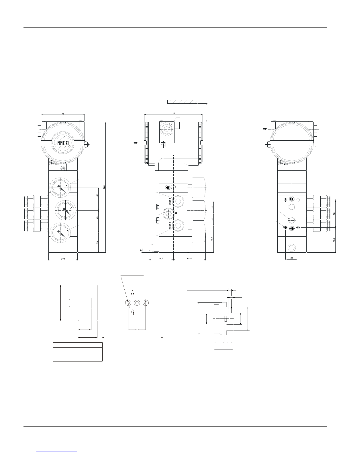
Installation
(in)
1.9
5
2.1
7
(in)
Double Action - Air to Open (Fail Close)
Connect Output 1 (OUT1) of the positioner to the input identified as OPEN in the actuator, and
connect Output 2 (OUT2) of the positioner to the input CLOSE in the actuator.
Double Action - Air to Close (Fail Open)
Connect Output 2 (OUT2) of the positioner to the input identified as OPEN in the actuator, and
connect Output 1 (OUT 1) of the positioner to the input CLOSE of the actuator.
Single Action
Connect Output 1 (OUT1) of the positioner to the input of the actuator. Use a plu g to block Output 2
(OUT2).
VALVE POSITIONER
(3.27)
TERMINAL
WIRING
INPUT
PRESSURE
1/8-27 NPT
(10.24)
OUTPUT
PRESSURE 2
1/8-27 NPT
OUTPUT
PRESSURE 1
1/8-27 NPT
(2.17) (1.83)
LINEAR MAGNET
18
64.5
(2.54)
(0.71)
(1.77)(1.77)(1.77)
(1.53)
HOLE 6.3 (0.25)Ø
(2 PLACES)
OUTPUT 2
1/4-18 NPT
INPUT
1/4-18 NPT
OUTPUT 1
1/4-18 NPT
(0.35)
(4.45)
SOCKET SET
PLUG
(2.42)
MOUNTING HOLES FOR M6x1
SCREWS (2 PLACES)
Leave, at least, a 150mm (5.8 in) space,
for zero and span adjustments with the
magnetic tool.
(2.10) (0.94) (0.94)
ROTARY MAGNET
THREADS FOR SCREWS
6,5
(0.25)
All dimensions are in mm
ELECTRICAL
CONNECTION
EXHAUST
ORIFICES
M6x1 (4 PLACES)
)
)(
(
(0.94)
22.5
(0.89)
33
(1.30)
TRAVEL DIMENSION A
UP TO 15 mm (0.59)
UP TO 30 mm (1.18)
UP TO 50 mm (1.97)
UP TO 100 mm (3.94)
Note: Dimensions in mm
43 mm (1.7)
67 mm (2.64)
105 mm (4.13)
181 mm (7.12)
*ONLY FOR 50 AND 100 mm TRAVELS.
15
(0.59)
69
21
(2.72)
(0.83)
15 *
(0.59)
A
22
(0.87)
39
(1.54)
(0.51)
24
50
(1.97)
(0.954)
13
1.3
Page 12
FY303 - Operation, Maintenance and Instructions Manual
R
REMOTE HALL SENSOR
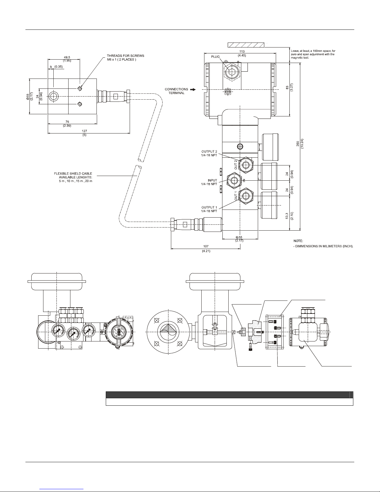
Figure 1.1 - FY303 Dimensional Drawing
ROTATY
MAGNETY
BRACKET
LOCK
VALVE STEM
ROTATY
MAGNET
M6x1 SCREWS
(4 PLACES)
POSITIONER
BRACKET
POSITIONE
Figure 1.2 - Positioner on Rotary Actuator
NOTE
Included in the package content the centralizer device of rotary magnet. See figure 1.13.
1.4
Page 13
Installation
LINEAR MAGNET
BRACKET
VALVE YOKE
POSITIONER
VALVE STEM
LINEAR MAGNET
CENTRALIZER DEVICE
BRACKET
M6x1 SCREWS
(4 PLACES)
POSITIONER
OUT 2OUT 1
IN
Figure 1.3 - Positioner on Linear Actuator
NOTE
Included in the package content the centralizer device of linear magnet. See figure 1.12.
1.5
Page 14
FY303 - Operation, Maintenance and Instructions Manual
Electronic Housing Rotating
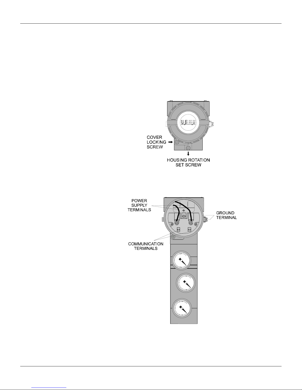
The electronic housing can be rotated in order to have a better position of the digital display. To
rotate it, use the Housing Rotation Set Screw. (See Figure 1.4).
The local indicator itself can also be rotated. (See Figure 2.4).
Electric Wiring
Reach the wiring block by removing the Electrical Connection Cover. T his cover can be locked by
the cover locking screw. To release the cover, rotate the locking screw clockwise.
The wiring block has screws on which fork or ring-type terminals can be fastened.
Figure 1.4 - Cover Locking and Housing Rotation Set Screw
For convenience there are two ground term inals: one inside the cover and one external, located
close to the conduit entries. (See Figure 1.5).
The FY303 uses the 31.25 kbit/s voltage mode opti on for t he physic al s ig nali ng. A ll other devic es o n
the same bus must use the same signaling. All devic es are connected in parallel along the same
pair of wires.
Various types of Profibus devices may be connected on the same bus.
1.6
Figure 1.5 - Wiring Block
Page 15
Installation
The FY303 is powered via the bus. The limit for such devices is according to the DP/PA coupler
limitations for one bus for non-intrinsically safe requirement. In hazardous area, the number of
devices may be limited by intrinsically safe r estrictions, acc ording to the c oupler DP/PA and barriers
limitations.
WARNING
HAZARDOUS AREAS
In hazardous areas with explosion proof requirements, the covers must be tightened with at least 8 turns. In
order to avoid the penetration moisture or corrosive gases, tighten the O’ring until feeling the O'ring touching
the housing. Then, tighten more 1/3 turn (120°) to guarantee the sealing. Lock the covers using the locking
screw.
In hazardous zones with intrinsically safe or non-incentive requirements, the circuit entity parameters and
applicable installation procedures must be observed.
Cable access to wiring connections is obtained by the two conduit outlets. Conduit threads should be sealed
by means of code-approved sealing methods. The unused outlet connection should be plugged and sealed
accordingly.
Should other certifications be necessary, refer to the certification or specific standard for installation
limitations.
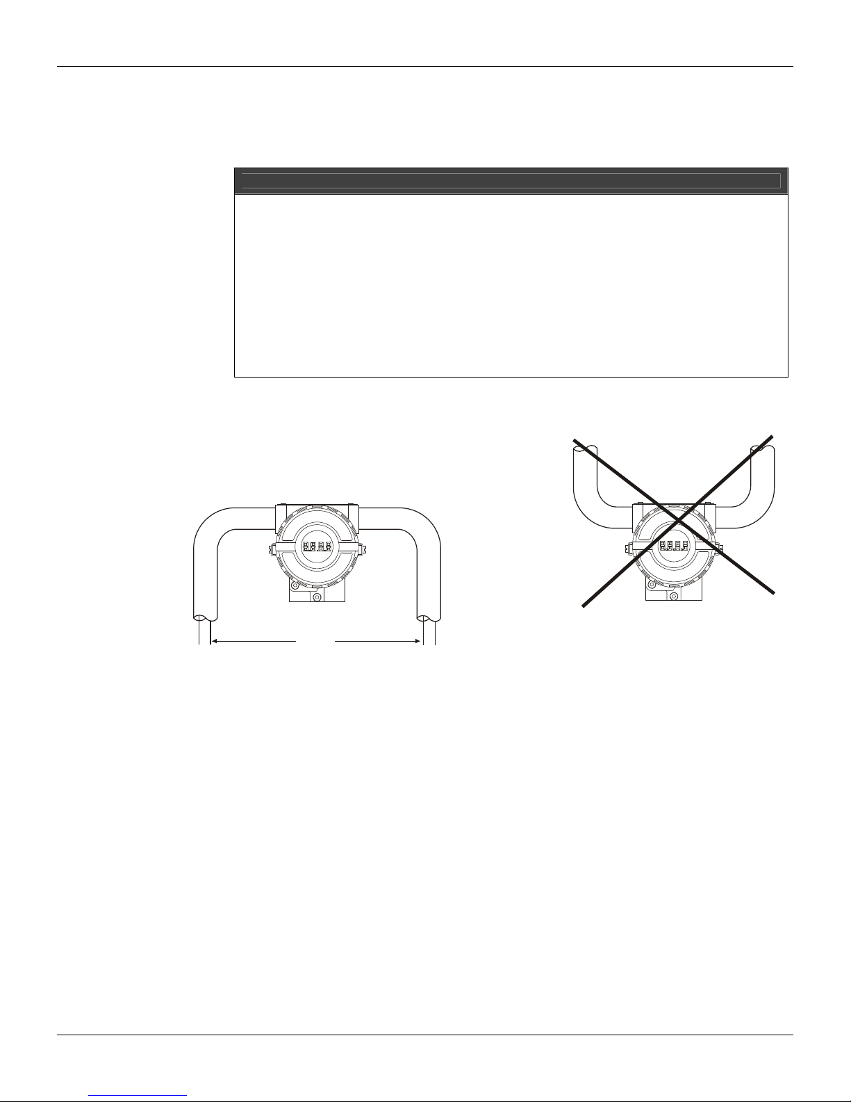
The Figure 1.6 - Conduit Installation Diagra m shows the correct installation of the conduit, in ord er
to avoid penetration of water, or other substance, which may cause malfunctioning of the
equipment.
WIRES
CORRECT INCORRECT
Figure 1.6 - Conduit Installation Diagram
The FY303 is protected against reverse polarity, and can withstand ± 35 Vdc without damage, but it
will not operate when in reverse polarity.
Topology and Network Configuration
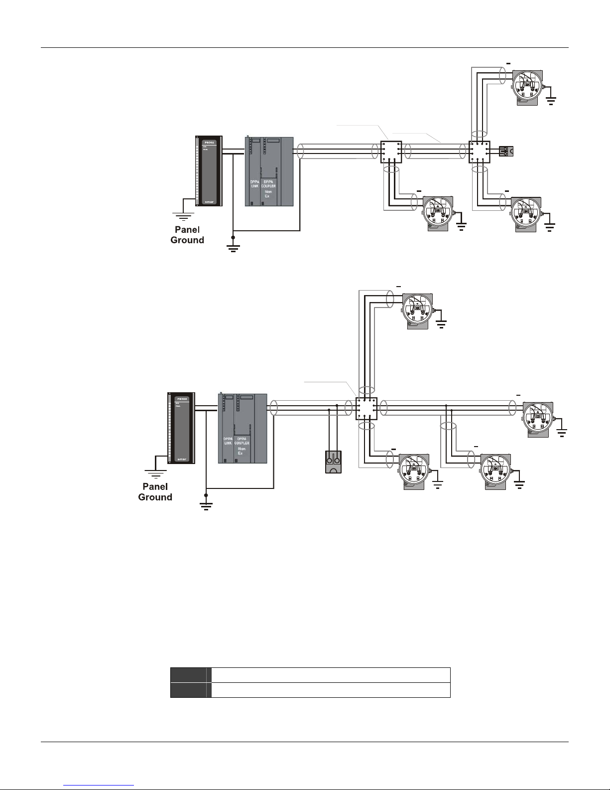
Bus topology (See Figure 1.7) and tree topolog y (See Figure 1.8) ar e supported. Both types have a
trunk cable with two terminations. The devices are connected to the trunk via sp urs. The spurs may
be integrated in the device giving zero spur length. A spur may connect more than one device,
depending on the length. Active couplers may be used to extend spur length.
Active repeaters may be used to extend the trunk length.
The total cable length, including spurs, bet ween any two devices in the Fi eldbus should not exceed
1900m.
The connection of couplers should be kept less than 15 per 250m. In following figures the
DP/PA link depends on the application needs.
1.7
Page 16
FY303 - Operation, Maintenance and Instructions Manual
r
S
r
+
+
-
-
Analog
Ground
Junction
Box
Shield
Spur
Figure 1.7 - Bus Topology
Terminato
Enabled
+
pur
+
Terminato
++
Spur
Intrinsic Safety Barrier
When the Fieldbus is in an area requiring intrinsic safety, a barrier must be inserted on the trunk
between the power supply and the DP/PA coupler, when it is Non-Ex type.
Use of SB302 is recommended.
Jumper Configuration
In order to work properly, the jumpers J1 and W1 located in the FY303 main board must be correctly
configured.
J1
W1
Junction
Box
+-+
-
Coupler
+
Analog
Ground
This jumper enables the simulation mode parameter in the AO block.
This jumper enables the local adjustment programming tree.
Figure 1.8 - Tree Topology
+
+
1.8
Page 17
CO
SSO
Power Supply
The FY303 receives power from the bus via the signal wiring. The power supply ma y come from a
separate unit or from another device such as a controller or DCS.
The voltage should be between 9 to 32 Vdc for non-intrinsic safe applications.
A special requirement applies to the power supply used in an intrinsically safe bus and depe nds on
the type of barrier used.
Use of PS302 is recommended as power supply.
Air Supply Requirements
Before the air supply is connected to the positioner, we recommend the hose is opened freely for 2
to 3 minutes to allow any contamination to be blown out. Direct the air jet into a large pa per bag to
trap any water, oil, or other foreign materials. If this indic ates that the air system is contaminated, it
should be properly cleaned.
As soon as the positioner is connected and started, internal air leakage will provide protection
against corrosion and prevent the ingress of moisture. For this reason, the air supply pressure
should always be kept on.
Recommendations for an Instrument Air System
Instrument air quality shall be superior to that of industrial compressed air. Humidity, airborne
particles and oil may impair the instrument operation, either temporarily or perma nently in case of
internal parts wearing.
As per standard ANSI/ISA S7.0.01 – 1996 - Quality Standard for Instrument Air, instrument air shall
have the following characteristics:
Dew point
Size of particles (airborne)
Oil content
Contaminants
This standard recommends that the compressor intake be located in an area free from process spills
and fitted with and adequate filter. It also recommends the use of no n-lubricated type compressors,
in order to prevent air contamination by lubricating oil. Where lubricated type compressors are
adopted, there shall be used means to make the air oil free.
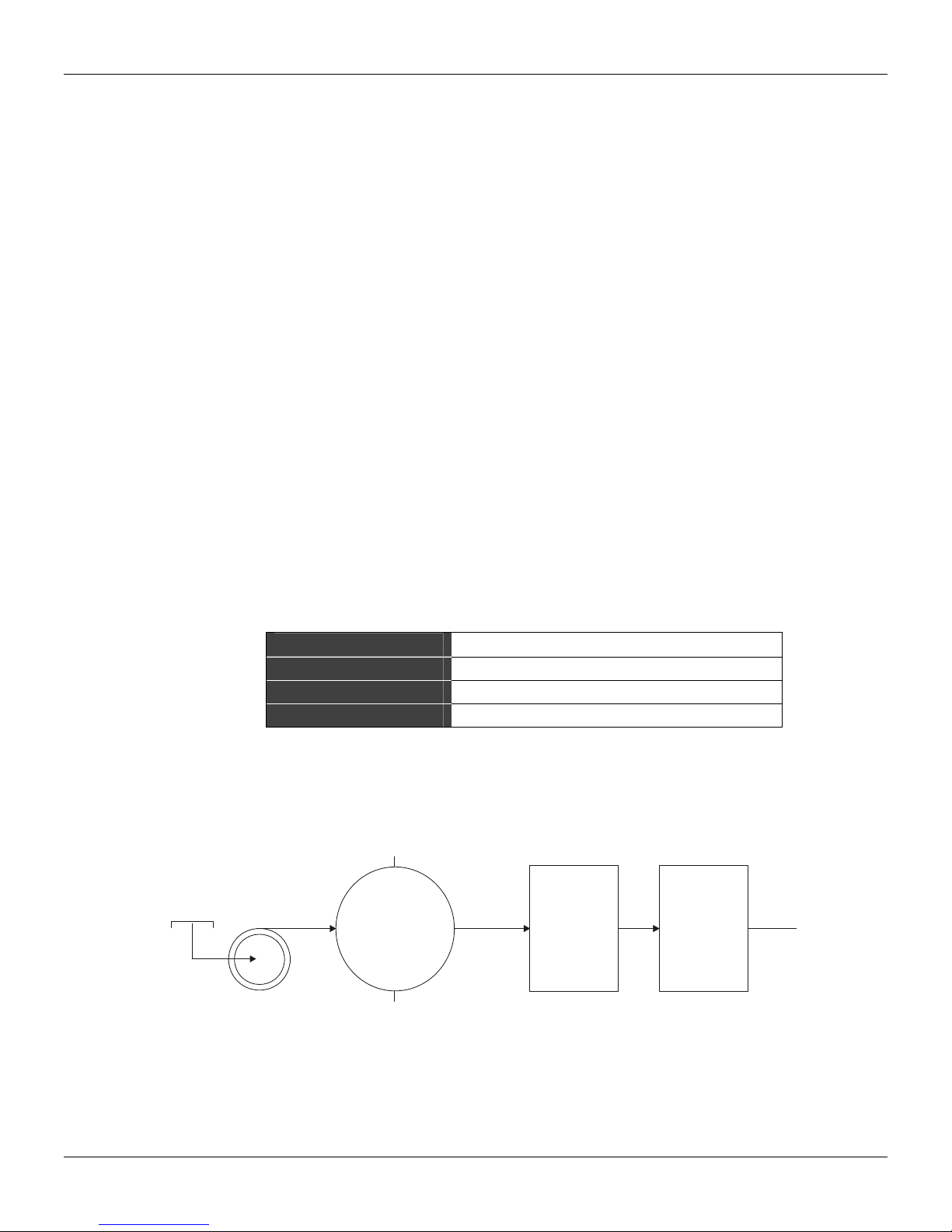
The figures 1.9 and 1.10 show a typical system for air supply and air quality conditioning.
10°C below minimum instrument temperature
40 µm (maximum)
1 ppm w/w (maximum)
free from corrosive flammable gases
Installation
COMPRESSOR
INTAKE
MPRE
R
AFTERCOOLER
Figure 1.9 - Air Supply System
CONDENSATE
SEPARATOR
WITH DRAIN
AIR RECEIVER
WITH DRAIN
1.9
Page 18
FY303 - Operation, Maintenance and Instructions Manual
OIL AND WATER
MIST PREFILTER
WITH DRAIN
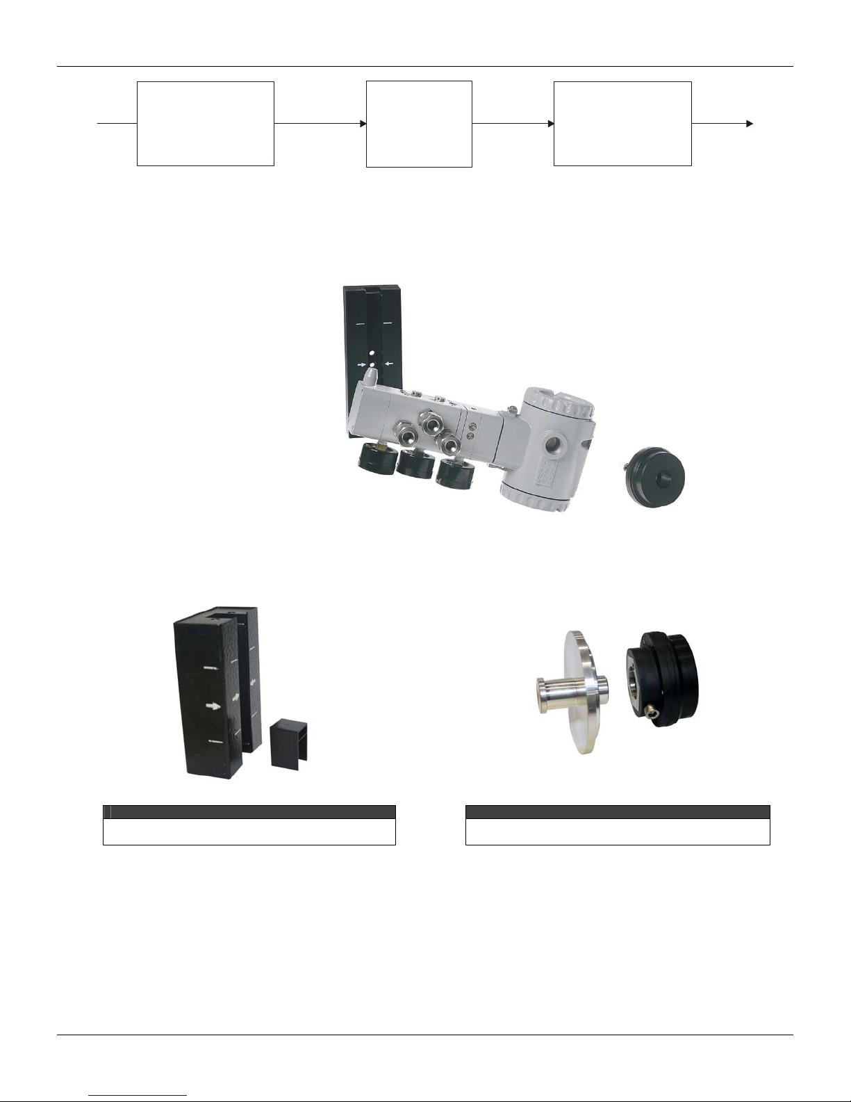
Figure 1.10 - Air Quality Conditioning System
Rotary and Linear Magnet
Magnet models are linear and rotary, for utilization on linear and rotary actuators.
Magnet Centralizer Device
AIR
DRYER
DRY AIR
AFTERFILTER
Figure 1.11 – Linear and Rotary Magnet Models
Centralizer device of linear magnet is used for all type of
linear bracket.
NOTE
Figure 1.12 – Centralizer device of linear magnet
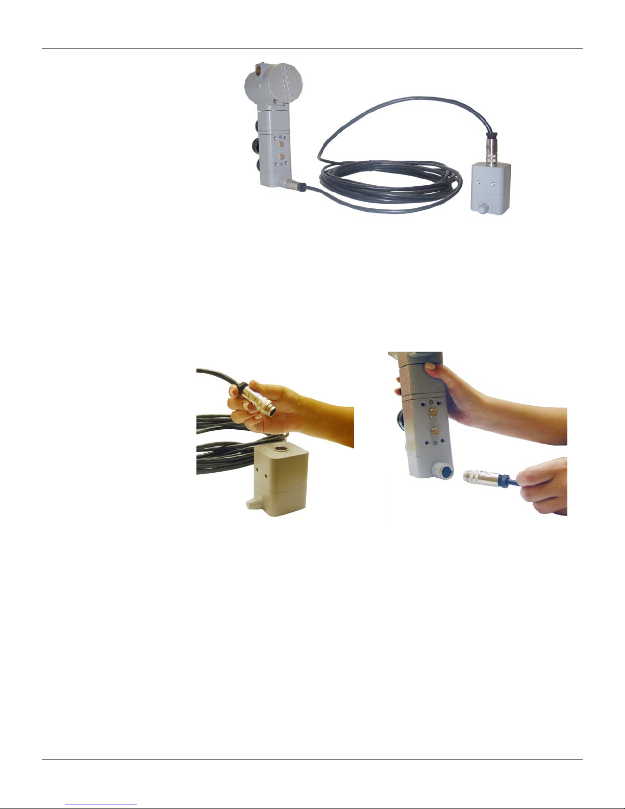
Remote Hall Sensor
The remote Hall magnetic sensor is an accessory recommended for high temperature and extreme
vibration applications. It prevents excessive wear of the equipment and, conse quently, the reduction
of its useful time.
1.10
Centralizer device of linear magnet is used only for
universal rotary bracket.
NOTE
Figure 1.13 - Centralizer device of rotary magnet
Page 19
Installation
Figure 1.14 - Remote Hall Sensor
The electric signals on the remote sensor’s connection to que equipment are of low intensity.
Therefore, when installing the cable inside the conduit (maximum limit 20 meters length) keep it
away from possible sources of induction and/or magnetic interference. The cable supplie d by Smar
is shielded for excellent protection against electromagnetic interference, but despite this protection
avoid the cable sharing the same conduit with other cables.
The connector for remote Hall sensor is easy handling and simple installation.
See the installation procedure:
Figure 1.15 - Connecting the Cable to the
Remote Hall Sensor
Figure 1.16 - Connecting the Cable to the
Positioner
1.11
Page 20

FY303 - Operation, Maintenance and Instructions Manual
1.12
Page 21
Section 2
OPERATION
Functional Description - Output Module
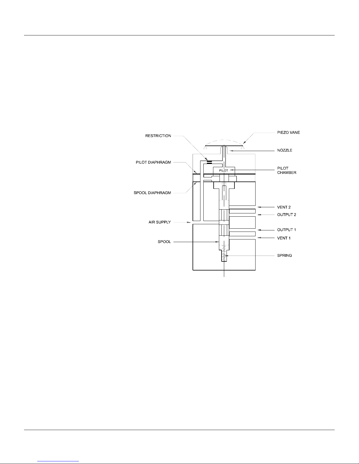
The main parts of the output module are the p ilot, servo, Hall Effect sensor and the output control
circuit.
The control circuit receives a digital setpoint sign al from the CPU and a feedback signal from the
Hall Effect sensor.
The pneumatic circuit is based on a well-known and widely adopted tec hnology, which is describe d
on item Nozzle-and-Vane and Spool.
Figure 2.1 - Pneumatic Transducer Schematic
A piezoelectric disk as flapper in the pilot stage. The flapper is deflected when the control circuit
applies a voltage. A small stream of air flowing throug h the nozzl e is obstr ucted causi ng an i ncre ase
in pressure in the pilot chamber; this is called the pilot pressure.
The pilot pressure is too low, with flowing capacity, and for this reason it must be amplified in the
servo section. The servo section includes a diaphragm in t he pi lot chambe r and a sm aller one in the
spool chamber. The pilot pressure applies a force at the pilot chamber's diaphragm which, in the
equilibrium state, will be equal to the force applied by the spool valve at the smaller diaphragm
which is in the spool chamber.
Therefore, upon every position change caused by the positioner, the pilot pressure increases or
decreases as explained in the pilot stage section; such change in pilot pressure causes an upward
or downward valve travel which alters the pressure at output 1 and output 2 until a new equilibrium
is reached, which results in a new valve position.
2.1
Page 22
FY303 – Operation, Maintenance and Instructions Manual
Functional Description-Electronics
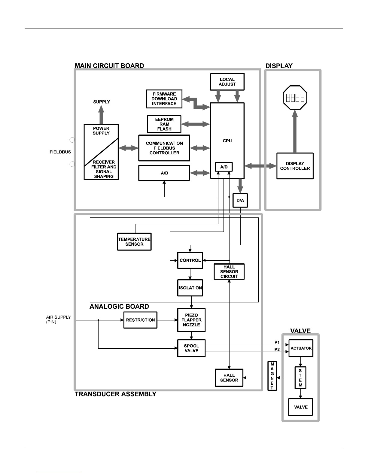
Refer to the block diagram. The function of each block is described below.
2.2
Figure 2.2 - FY303 Block Diagram
Page 23

Operation
D/A
Receives the signal from the CPU and converts it to an analog voltage proportional the desired
position, used by the control.
Control
Controls the valve position according to the data received from the CPU and the Hall effect sensor
feedback.
A/D
Receives the signal from the Hall Sensor and converts it to a di gital value proportional to the actual
valve position.
Hall Effect Sensor
Measures the position actual and feedback to the control and CPU.
Temperature Sensor
Measures the temperature of the transducer assembly.
Isolation
Its function is to isolate the fieldbus signal from the piezoelectric.
EEPROM
A non-volatile memory which stores configuration data as a backup.
Central Processing Unit (CPU), RAM, PROM and EEPROM
The CPU is the intelligent portion of the positioner, being responsible for the management and
operation of block execution, self-diagnostics and commun ication. The program is stored in PROM.
For temporary storage of data there is a RAM. The data in the RAM is lost if the power is switched
off, however the device also has a nonvolatile EEPROM where data that must be retained is stored.
Examples of such data are: calibration and valve configuration.
Communication Controller
A monitor line activity, modulates and demodulates communication signals and inserts and deletes
start and end delimiters.
Power Supply
The positioner circuit receives supply from a 9 to 32 Vdc power supply. Use of PS302 is
recommended.
Display Controller
Receives data from the CPU and drives the (LCD) Liquid Crystal Display.
Local Adjustment
Local adjustment is provided by means of two magnetic naturall y actuated switches with no external
electric or mechanical contact, by using a magnetic screwdriver.
Piezo Flapper Nozzle
The unit flapper nozzle converts the movement of piezoelectric i nto a pneumatic signal to control
pressure in the pilot chamber.
Restriction
The restriction and the nozzle form a pressure-divided circuit. Air is supplied to the nozzle throug h a
restriction.
Spool
The spool ensures a quick valve positioning by providing a greater air flow than one provided b y the
restriction.
2.3
Page 24

FY303 – Operation, Maintenance and Instructions Manual
Introduction to Fieldbus Application
From a Fieldbus point of view, the FY303 is not an assembly of electronics, housing and sensor
forming a positioner, but a network node containing function blocks.
Basically, it contains one output transducer block, one resource block, one dis play transducer block
and Analog Output block.
These blocks are models of the functionality that the FY303 provides for a control system. They can
loosely be said to make up part of the application that is performed in the FY303.
Function Blocks
Models the basic user configurable functionality of the device. Typically this functionality was
previously available in individual devices. For example, the analog output block provides the
functionality of what is known as a positioner. It makes the Fieldbus signal ava ilable to the FY303
output hardware. It also optionally performs output reversing.
All information regarding to Function Blocks are available on the “Function Blocks Instruction
Manual”.
Transducer Blocks
These are responsible for the interface between the function blocks a nd the FY303 output channel
hardware.
Output transducer block
It is responsible for the processing of the output signal, such as output characterization and trim.
Display transducer block
It is responsible for the display and local adjustment.
Physical Block
It is responsible for monitoring the operation of the device. It also contai ns device information such
as serial equipment number.
The Local Indicator
The local indicator is required for signaling and operation in local adjustment. The parameters
desired by the user to be viewed on the LCD display should be configured in the display block.
Normal Indicator
During normal operation, the FY303 remains in the monitoring mode and the display will always
indicate the variable of monitoring configured in the display block. T he user can configure up to six
parameters and chooses up to two to switching on the LCD. F or details, please see the general
manual. It is recommended configuring the position of the valve in % (percentage).
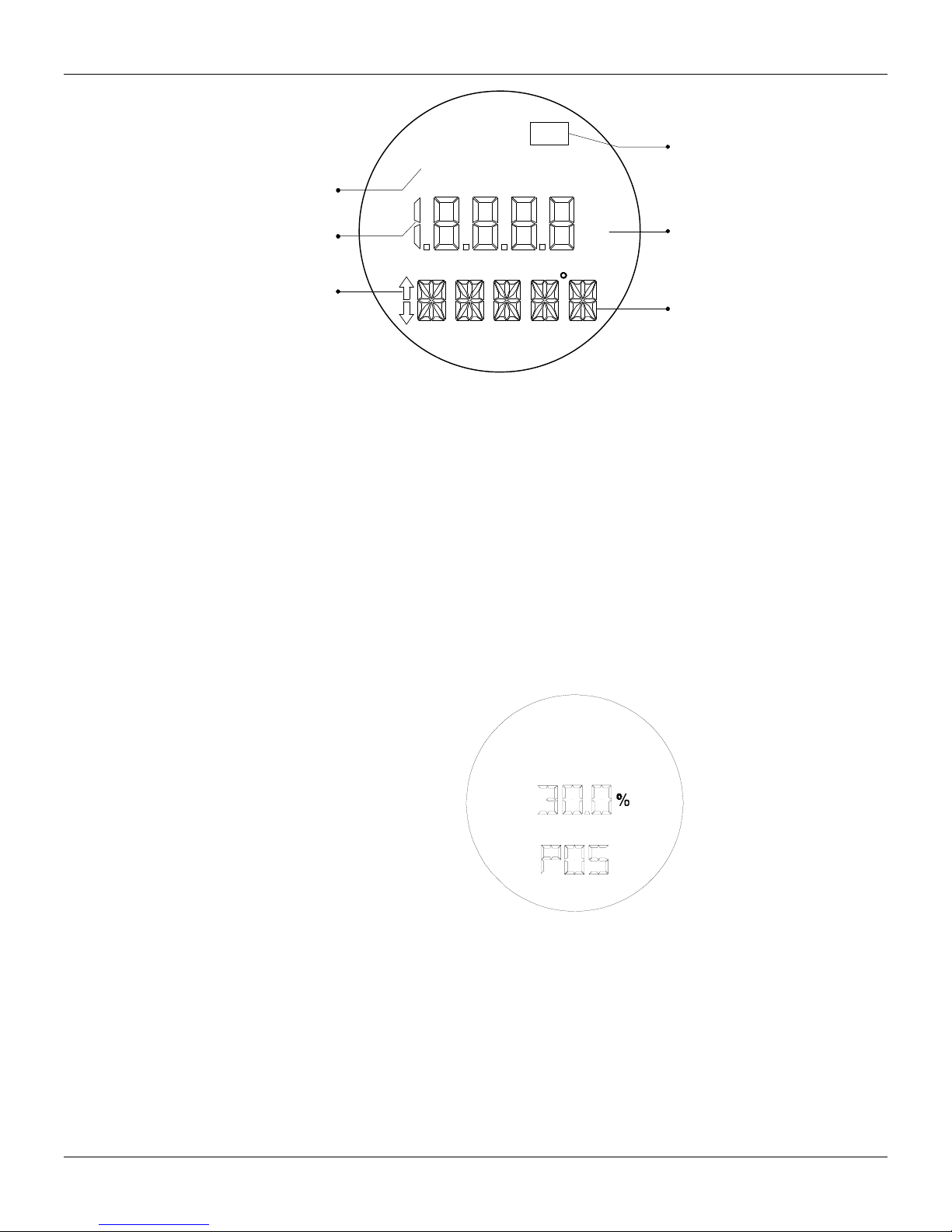
The possible configuration and monitoring operation are shown on.
2.4
Page 25
Operation
MD
INDICATES ACTIVE MUL TIDROP MODE
FIX
INDICA T ES T HAT THE CONSTANT
OUTPUT MODE IS ACTIVE
VARIABLE FIELD
INDICATES THE POSSIBILITY
TO CHANGE / ADJUST
VARIABLE / MODE
%
READOUT IN PERCENT AGE
UNIT AND FUNCTION FIELD
Figure 2.3 - Local Indicator
Upon receiving power, the FY303 initializes the position ind ication on the d isplay, by sho wing model
FY303 and its software version (X.XX).
Monitoring
During normal operation, FY303 remains in the monitoring mode. The display sim ultaneously sho ws
readout and some other information.
Normal displaying is interrupted when the magnetic tool is placed in orifice marked as “Zero” and the
indicator “MD” is showed on the display. After this, withdraw the magnetic tool off the Z orifice and
put it in the orifice marked with the “S” letter.
With the tool in the orifice, wait for 3 seconds. Withdraw again the magnet tool and wait for 3
seconds. Put it now in the S orifice and it will app ear the message of “LOC ADJ“ (Local Adjust).
Withdraw the tool and put it in the Z orifice. After this, you can browse to all the parameters
configured in the display block.
Figure 2.4 - Typical Indicator
2.5
Page 26

FY303 – Operation, Maintenance and Instructions Manual
2.6
Page 27

Section 3
CONFIGURATION
This section describes the characteristics of the blocks in the FY303. They follow the Profibus PA
specifications, but in terms of transducer blocks, the output transducer block and display, they have
some special features on top of this.
The FY303 contains one Analog Output block, one resource block, one display transducer block and
one transducer block.
For explanation and details of function blocks, see the “Function Blocks Manual”.
The 303 Smar family is integrated in Simatic PDM, from Siemens. It is possible to integrate any 303
Smar devices into any configuration tool for Profibus PA devices. It is necessary to provide a Device
Description or Drive according to the configuration tool. In this manual is taken several examples
using Simatic PDM.
Offline Configuration
1. First run “Download to PG/PC” option to assure valid values.
2. Run after the Menu Device option to configure the required parameters using the related menus.
It is not advisable to use the “Download to Device” option. This function can misconfigure the equipment.
Transducer Block
Transducer block insulates function block from the specific I/O hardware, such as sensors,
actuators. Transducer block controls access to I/O through manufacturer specific implementation.
This permits the transducer block to execute as frequently as necessary to obtain good data from
sensors without burdening the function blocks that use the data. It also insulates the function block
from the manufacturer specific characteristics of certain hardware. By accessing the hardware, the
transducer block can get data from I/O or passing control data to it. The connection between
Transducer block and Function block is called channel. These blocks can exchange data from its
interface.
Normally, transducer blocks perform functions, such as linearization, characterization, temperature
compensation, control and exchange data to hardware.
How to Configure a Transduce r Block
The transducer block has an algorithm and a set of contained parameters.
The algorithm describes the behavior of the transducer as a data transfer function between the I/O
hardware and other function block. The set of contained parameters, it means, you are not able to
link them to other blocks and publish the link via communication, defines the user interface to the
transducer block. They can be divided into Standard and Manufacturer Specific.
The standard parameters will be present for such class of device, as pressure, temperature,
actuator, etc., whatever is the manufacturer. Oppositely, the manufacturers’ specific ones are
defined only for its manufacturer. As common manufacturer specific parameters, we have calibration
settings, material information, linearization curve, etc.
When you perform a standard routine as a calibration, you are conducted step by step by a method.
The method is generally defined as guide line to help the user to make common tasks. The
configuration tool identifies each method associated to the parameters and enables the interface to
it.
NOTE
3.1
Page 28
FY303 – Operation, Maintenance and Instructions Manual
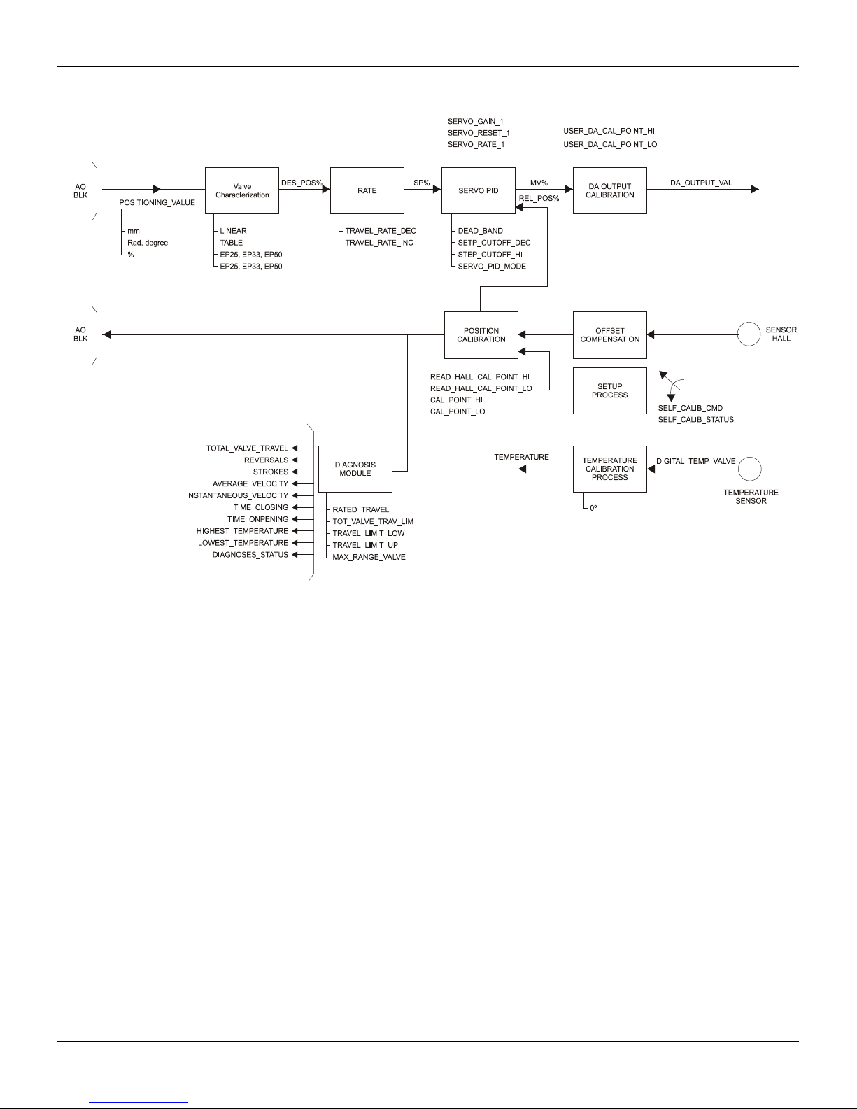
Functional Diagram of the Posit ioner Transducer Block
Figure 3.1 - Functional Diagram of the Positioner Transducer Block
3.2
Page 29

Transducer Block Standar d P ar a m e ter De s cri pt ions
Parameter
Transducer Block Description
Serial-number of the actuator belonging to the positioner or the electronic device.
Fail-Safe position for power-loss of t he actuator, the valve:
3 = none / remains in actual position
Name of Actuator-Manufacturer.
Type of actuator:
3 = others
Minimum of time to move from OP EN to CLOSE position (in sec.) for tot al system (positioner, actuator and
valve). Measured while commissioning.
Minimum of time to move from CLOS E to OPEN position (in sec.) for total s ystem (positioner, actuator and
valve). Measured while commissioning.
Manufacturer specific type identification of the additional component (e.g. a gearbox, booster) mounted
Installation date of the additional component (e.g. gearbox, booster) mounted between the actuator and valve
Manufacturer name of the additional component (e.g. gearbox, booster) mounted between the actuator and
Serial number of the additional component (e.g. gearbox, booster) mounted between the actuator and valve.
Dead band in percent of travel span. Travel span correspondents to OUT_SCALE.
Date of last configuration of the device.
Type of linearization.
The actual command variable for the final control element in units of OUT_SCALE. Status BAD will drive the
actuator to the fail-safe position defined by ACTUATOR_ACTION.
Nominal stroke of the valve in units of OUT_SCALE.
Initiation of a device-specific (manufacturer specific) calibration-procedure.
255 = abort current calibration-procedure
Proportional-action coefficient for both moving directions.
Derivative-action coefficient for both moving directions.
Integral-action coefficient for both moving directions.
position goes to the limit position
With electric actuator, the actuator goes motor-driven to the limit position CLOSE.
When the servo setpoint goes above the defined percent of span, the position goes to the limit position OPEN.
With electro-pneumatic actuator, this is done by totally ventilate/fill i ng of the actuator (ref. to fail -safe position.)
The index parameter identifies which element of the table is in the X_VALUE and Y_VALUE parameter
currently
ACTUATOR_ SER_NUM
0 = not initialized
ACTUATOR_ACTION
ACTUATOR_MAN
ACTUATOR_TYPE
ACT_STROKE_TIME_DEC
ACT_STROKE_TIME_INC
1 = opening (100%)
2 = closing (0%)
0 = electro-pneumatic
1 = electric
2 = electro-hydraulic
Configuration
ADD_GEAR_ID
ADD_GEAR_INST_DATE
ADD_GEAR_MAN
ADD_GEAR_SER_NUM
DEADBAND
DEVICE_CALIB_DATE
DEVICE_CONFIG_DATE
LIN_TYPE
FEEDBACK_VALUE
POSITIONING_VALUE
RATED_TRAVEL
SELF_CALIB_CMD
between the actuator and valve.
valve.
Date of last calibration of the device.
0 = no linearization (mandatory)
1 = linearization table (optional)
240 Manufacturer specific
249 Manufacturer specific
250 Not used
251 None
252 Unknown
253 Special
The actual position of the final control element in units of OUT_SCALE.
0 = default value; no reaction of the field device (mandatory)
1 = start zero point adjustment (optional)
2 = start self calibration / initialization (optional)
7 = reset total valve travel limit exceeded“ CB_TOT_VALVE_TRAV (optional)
and reset Accumulated valve travel“ TOTAL_VALVE_TRAVEL (optional)
10 = reset internal control loop disturbed“ CB_CONTR_ERR (optional)
255 = abort current calibration-procedure (optional)
Smar:
0 = default value; no reaction of the field device
2 = start self calibration / initialization
7 = reset total valve travel
SERVO_GAIN_1
SERVO_RATE_1
SERVO_RESET_1
SETP_CUTOFF_DEC
SETP_CUTOFF_INC
TAB_ENTRY
When the servo setpoint goes below the defined percent of span, the
CLOSE.
With electro-pneumatic actuator, this is done by totally ventilate/fill i ng of the actuator (ref. to fail -safe position.)
3.3
Page 30

FY303 – Operation, Maintenance and Instructions Manual
Parameter
Transducer Block Description
The X_Y_VALUE parameter contains one value couple of the table
it is necessary to use a certain number of table
TAB_MAX_NUMBER is the maximum size (number of X_VALUE and Y_VALUE values) of the table in the
device.
Contains the actual numbers of entries i n the table. It shall be c alculated after the t ransmission of the table is
finished.
Result or status of the device-specific (manufacturer specific) calibration-procedure.
12 = Pressure problem.
The modification of a table in a device inf luences the measurement or actuation algorithms of the device.
Therefore an indication of a starting and an end point is necessary. The TAP_OP_CODE controls the
Value,
stop an interaction (TAB_OB_CODE 1 and
bility check in the device. The result of this check is indicated in the
> 128 manufacturer specific
Accumulated valve travel in nominal duty cycles.
Limit for the TOTAL_VALVE_TRAVEL in nominal duty cycles.
Lower limit of the valve position in percent of travel span. Travel span correspondents to OUT_SCALE.
Configurable seconds to full span change (closing time of the valve) in seconds.
Configurable seconds to full span change (opening time of the valve) in seconds.
Date of last valve maintenance.
Serial-number of the valve belonging to the positioner or the electronic device.
Type of valve:
2 = rotary moving valve, multi-turn
TAB_X_Y_VALUE
TAB_MIN_NUMBER
TAB_MAX_NUMBER
TAB_ACTUAL_NUMBER
SELF_CALIB_STATUS
TAB_OP_CODE
TAB_STATUS
For device internal reasons (e.g. for calculation), some times
values in minimum. This number is provided in the TAB_MIN_NUMBER parameter.
0 = undetermined (mandatory)
2 = aborted (optional)
4 = error in mechanical system (optional)
11 = timeout (optional)
20 = aborted by means of “Emergency override active“ CB_OVERRIDE (optional)
30 = zero point error (optional)
254 = erfolgreich (optional)
255 = no valid data (optional)
Smar:
0 = Self Calibration OK.
3 = No magnet part detected.
4 = Error in mechanical system.
11 = Timeout.
transaction of the table.
0: not initialized
1: new operation characteristic, first value (TAB_INDEX=1), old curve cleared
2: reserved
3: last value, end of transmission, check table, swap the old curve wit h the new curve, and actualize
ACTUAL_NUMBER.
4: delete point of table with actual index (optional), sort records with increasing Charact-Inputassign new indexes, and decrement CHARACT_NUMBER.
5: insert point (Charact-Input-Value relevant) (optional), sort records with increasing Charact-InputValue, assign new indexes. Increment CHARACT_NUMBER.
6: replace point of table with actual index (optional).
It is possible to read a table or parts of the table without s tart and
3). The start is indicated by set TAB_ENTRY to 1.
It is common to provide a plausi
TAB_STATUS parameter.
0: not initialized
1: good (new table is valid)
2: not monotonous increasing (old table is valid)
3: not monotonous decreasing (old table is valid)
4: not enough values transmitted (old table is valid)
5: too many values transmitted (old table is valid)
6: gradient of edge too high (old table is valid)
7: Values not excepted (old values are valid)
8 - 127 reserved
TOTAL_VALVE_TRAVEL
TOT_VALVE_TRAV_LIM
TRAVEL_LIMIT_LOW
TRAVEL_LIMIT_UP
TRAVEL_RATE_DEC
TRAVEL_RATE_INC
VALVE_MAINT_DATE
VALVE_MAN
VALVE_SER_NUM
VALVE_TYPE
Upper limit of the valve position in percent of travel span. Travel span correspondents to OUT_SCALE.
Name of Valve Manufacturer.
0 = linear moving valve, sliding valve
1 = rotary moving valve, part-turn
Table 3.1 - Transducer Block Standard Parameter Description
3.4
Page 31

Transducer Block Specif ic P ar am eter De s criptions
Parameter Transducer Block Description
Air to Open/Close.
AIR_TO
CAL_POINT_HI
CAL_POINT_LO
CAL_MIN_SPAN
CAL_UNIT
FEEDBACK_CAL
CAL_CONTROL
BACKUP_RESTORE
SECONDARY_VALUE
SECONDARY_VALUE_UNIT
CAL_TEMPERATURE
{0, "Open"},
{1, "Close"}
The highest calibrated point.
The lowest calibrated point.
The minimum calibration span value allowed
Engineering units code for the calibration values, %(1342).
The position value used to correct a calibration.
Enable and disable a calibration method.
This parameter is used to do backup or to restore configuration data.
{ 0, "None" },
{ 1, "Factory Cal Restore" },
{ 2, "Last Cal Restore" },
{ 3, "Default Data Restore" },
{ 5, "Sensor Data Restore" },
{ 11, "Factory Cal Backup" },
{ 12, "Last Cal Backup" },
{ 15, "Sensor Data Backup" }
The secondary value related to the sensor.
The engineering units to be used with the secondary value, °C (1001).
The temperature value used to calibrate the temperature sensor.
Configuration
SERVO_PID_BYPASS
SERVO_PID_ERROR_PER
SERVO_PID_INTEGRAL_PER
SERVO_MV_PER
MODULE_SN
REVERSALS
STROKES
AVERAGE_VELOCITY
INSTANTANEOUS_VELOCITY
TIME_CLOSING
TIME_OPENING
MAX_RANGE_VALVE
HIGHEST_TEMPERATURE
LOWEST_TEMPERATURE
Enable and disable the servo PID.
{0, "Disable" },
{1, "Enable" }
The percent error value for the servo PID.
The percent integral value for the servo PID.
The percent measured value for the servo PID.
The module manufacturer identific ation number.
Number of reversals.
Number of strokes.
The average velocity of valve.
The instantaneous velocity of valve.
The time to go from 100.0% to 0.0%.
The time to go from 0.0% to 100.0%.
The maximum range valve.
The highest measured temperature.
The lowest measured temperature.
3.5
Page 32

FY303 – Operation, Maintenance and Instructions Manual
Parameter Transducer Block Description
Indicates the status of diagnoses:
{ 0, "None"},
{ 2, "Output Module Not Initialized"},
{ 4, "No Valve Movement or Slow Valve Movement or Low Air Supply or No Magnet Detected"},
{ 6, "(No Valve Movement or Slow Valve Movement or Low Air Supply or No Magnet Detected)
and (Output Module Not Initialized)"},
{ 8, "Travel Limit Exceeded"},
{ 10, "Travel Limit Exceeded and Output Module Not Initialized"},
{ 12, "Travel Limit Exceeded and (No Valve Movement or Slow Valve Movement or Low Air
Supply or No Magnet Detected)"},
{ 14, "(Travel Limit Exceeded) and (No Valve Movement or Slow Valve Movement or Low Air
Supply or No Magnet Detected) and (Output
Module Not Initialized)"},
DIAGNOSES_STATUS
{ 16, "Temperature Out of work range"},
{ 18, "Temperature Out of work range and Output Module Not Initialized"},
{ 20, "Temperature Out of work range and (No Valve Movement or Slow Valve Movement or
Low Air Supply or No Magnet Detected)"},
{ 22, "Temperature Out of work range and (No Magnet Detected and Output Module Not
Initialized)"},
{ 24, "Travel Limit Exceeded and Temperature Out of work range"},
{ 26, "Travel Limit Exceeded and Temperature Out of work range and Output Module Not
Initialized"},
{ 28, "Travel Limit Exceeded and Temperature Out of work range and (No Valve Movement or
Slow Valve Movement or Low Air Supply or No Magnet Detected)"},
{ 30, "Travel Limit Exceeded and Temperature Out of work range and (No Valve Movement or
Slow Valve Movement or Low Air Supply or No Magnet Detected) and Output Module Not
Initialized"},
{ 32, "Output Module Not Detected"}
DIGITAL_HALL_VALUE
HALL_COMPENSATED
Value and Status for Hall sensor.
Value for Hall sensor after compensation of offset.
Enable and disable for offset compensation.
HALL_OFFSET_CONTROL
{0, "Disable"},
{1, "Enable"}
READ_HALL_CAL_POINT_HI
READ_HALL_CAL_POINT_LO
DA_OUTPUT_VALUE
USER_DA_CAL_POINT_HI
USER_DA_CAL_POINT_LO
PIEZO_ANALOG_VOLTAGE
POT_DC
MAIN_LATCH
The highest calibrated point for Hall sensor.
The lowest calibrated point for Hall sensor.
Value and status for DA output.
The highest calibrated point for DA output.
The lowest calibrated point for DA output.
The analog voltage for piezo.
The value for POT DC.
MAIN ANALOG SWITCH USED BY HARDWARE.
3.6
Page 33
Parameter Transducer Block Description
Transport
2)
Indicates the condition of calibration process according to:
{ 16, "Default value set"},
XD_ERROR
{22, "Applied process out of range"},
{26, "Invalid configuration for request"},
{27, "Excess correction"},
{28, "Calibration failed"}
MAIN_BOARD_SN
THE ELECTRONIC MAIN BOARD SERIAL NUMBER.
This parameter is used to indicate EEPROM saving process.
EEPROM_FLAG
{ 0, "False"},
{ 1, "True"}
ORDERING_CODE
Indicates information about the sensor and control of factory production.
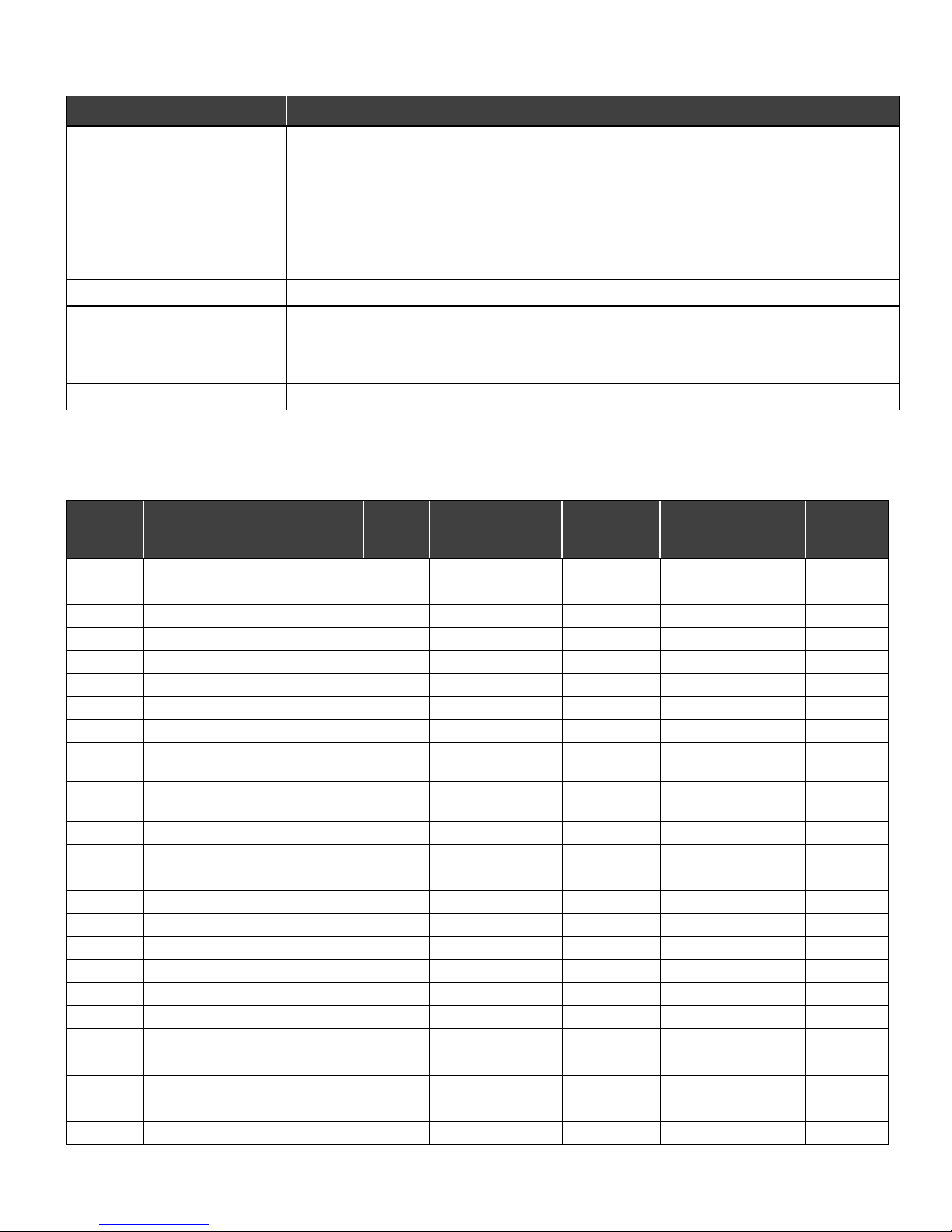
Table 3.2 - Transducer Block Specific Parameter Descriptions
Transducer Block Param ete r At t ribute Table
Relative
Index
Parameter Name
Object
Type
Data Type Store Size Access
9 ACT_STROKE_TIME_DEC Simple Float S 4 r C/a 10 ACT_STROKE_TIME_INC Simple Float S 4 r C/a 17 TAB_ENTRY
18 TAB_X_Y_VALUE
19 TAB_MIN_NUMBER
20 TAB_MAX_NUMBER
21 TAB_ACTUAL_NUMBER
1)
1)
1)
1)
1)
1)
1)
1)
1)
1)
1)
1)
1)
1)
1)
1)
1)
1)
1)
1)
22 DEADBAND Simple Float S 4 r,w C/a 23 DEVICE_CALIB_DATE Simple
24 DEVICE_CONFIG_DATE Simple
25 LIN_TYPE
1)
Octet
String
Octet
String
1)
S 16 r,w C/a -
S 16 r,w C/a -
1)
1)
32 RATED_TRAVEL Simple Float S 4 r,w C/a 33 SELF_CALIB_CMD Simple Unsigned8 S 1 r,w C/a 0
34 SELF_CALIB_STATUS Simple Unsigned8 N 1 r C/a 0
35 SERVO_GAIN_1 Simple Float S 4 r,w C/a 36 SERVO_RATE_1 Simple Float S 4 r,w C/a 37 SERVO_RESET_1 Simple Float S 4 r,w C/a 38 SETP_CUTOFF_DEC Simple Float S 4 r,w C/a 39 SETP_CUTOFF_INC Simple Float S 4 r,w C/a 45 TOTAL_VALVE_TRAVEL Simple Float D
4 r C/a 46 TOT_VALVE_TRAV_LIM Simple Float S 4 r,w C/a 47 TRAVEL_LIMIT_LOW Simple S 4 r,w C/a 0
48 TRAVEL_LIMIT_UP Simple Float S 4 r,w C/a 100
49 TRAVEL_RATE_DEC Simple Float S 4 r,w C/a -
1)
1)
1)
1)
1)
1)
Parameter
usage/
Type of
1)
-
1)
-
1)
-
1)
-
1)
-
1)
0
Configuration
Default
Mandatory/
Optional
(Class)
3.7
Page 34

FY303 – Operation, Maintenance and Instructions Manual
Parameter
Transport
1) 1) 1) 1) 1) 1)
Relative
Index
Parameter Name
Object
Type
Data Type Store Size Access
usage/
Type of
50 TRAVEL_RATE_INC Simple Float S 4 r,w C/a 51 VALVE_MAINT_DATE Simple Octet String S 16 r,w C/a 52 SERVO_GAIN_2 Simple Float S 4 r,w C/a 53 SERVO_RATE_2 Simple Float S 4 r,w C/a 54 SERVO_RESET_2 Simple Float S 4 r,w C/a 55 TAB_OP_CODE
56 TAB_STATUS
1)
1)
1)
1)
1)
1)
-
57 POSITIONING_VALUE Record DS_33 D 5 r C/a 58 FEEDBACK_VALUE Record DS_33 D 5 r C/a 59 VALVE_MAN Simple OctetString S 16 r,w C/a 60 ACTUATOR_MAN Simple OctetString S 16 r,w C/a 61 VALVE_TYPE Simple Unsigned8 S 1 r,w C/a 62 ACTUATOR_TYPE Simple Unsigned8 N 1 r C/a 63 ACTUATOR_ACTION Simple Unsigned8 S 1 r,w C/a 64 VALVE_SER_NUM Simple OctetString S 16 r,w C/a 65 ACTUATOR_SER_NUM Simple OctetString S 16 r,w C/a 66 ADD_GEAR_SER_NUM Simple OctetString S 16 r,w C/a 67 ADD_GEAR_MAN Simple OctetString S 16 r,w C/a 68 ADD_GEAR_ID Simple OctetString S 16 r,w C/a 69 ADD_GEAR_INST_DATE Simple OctetString S 16 r,w C/a 70 AIR_TO Simple Unsigned8 N 1 r,w C/a Open
71 CAL_POINT_HI Simple Float N 4 r,w C/a %
72 CAL_POINT_LO Simple Float N 4 r C/a %
73 CAL_MIN_SPAN Simple Float N 4 r C/a 1
74 CAL_UNIT Simple Unsigned16 N 2 r C/a %
75 FEEDBACK_CAL Simple Float N 4 r,w C/a %
76 CAL_CONTROL Simple Unsigned8 N 1 r,w C/a Disable
77 BACKUP_RESTORE Simple Unsigned8 S 1 r,w C/a None
78 SECONDARY_VALUE Record DS-33 D 5 r C/a
79 SECONDARY_VALUE_UNIT Simple Unsigned16 N 2 r C/a Celsius
80 CAL_TEMPERATURE Simple Float N 4 r,w C/a Celsius
81 SERVO_PID_BYPASS Simple Unsigned8 S 1 r,w C/a
82 SERVO_PID_ERROR_PER Record DS-33 D 5 r C/a
83 SERVO_PID_INTEGRAL_PER Record DS-33 D 5 r C/a
84 SERVO_MV_PER Record DS-33 D 5 r C/a
85 MODULE_SN Simple Unsigned32 S 4 r,w C/a
86 REVERSALS simple float S 4 r,w C/a
87 STROKES simple float S 4 r,w C/a
88 AVERAGE_VELOCITY simple float D 4 r C/a
89 INSTANTANEOUS_VELOCITY simple float D 4 r C/a
90 TIME_CLOSING simple float D 4 r C/a
91 TIME_OPENING simple float D 4 r C/a
Default
Not
Bypass
Mandatory/
Optional
(Class)
3.8
Page 35
Relative
Parameter
Transport
Index
Parameter Name
Object
Type
Data Type Store Size Access
usage/
Type of
92 MAX_RANGE_VALVE simple float S 4 r,w C/a
93 HIGHEST_TEMPERATURE simple float S 4 r,w C/a
94 LOWEST_TEMPERATURE simple float S 4 r,w C/a
95 DIAGNOSES_STATUS simple Unsigned8 N 1 r C/a None
96 DIGITAL_HALL_VALUE Record DS-33 D 5 r C/a
97 HALL_COMPENSATED simple float D 4 r C/a
98 HALL_OFFSET_CONTROL simple Unsigned8 N 1 r,w C/a Disable
99 READ_HALL_CAL_POINT_HI simple float S 4 r C/a
100 READ_HALL_CAL_POINT_LO simple float S 4 r C/a
101 DA_OUTPUT_VALUE Record DS-33 D 5 r C/a
102 USER_DA_CAL_POINT_HI simple float S 4 r C/a
103 USER_DA_CAL_POINT_LO simple float S 4 r C/a
104 PIEZO_ANALOG_VOLTAGE Record DS-33 D 5 r C/a
105 POT_DC simple Unsigned8 N 1 r,w C/a 128
106 MAIN_LATCH simple Unsigned8 S 1 r,w C/a 12
107 XD_ERROR simple Unsigned8 S 1 r C/a 0x10
108 MAIN_BOARD_SN simple Unsigned32 S 4 r,w C/a
109 EEPROM_FLAG simple Uunsigned8 D 1 r C/a
110 ORDERING_CODE array Unsigned8 S 50 r,w C/a
1) See table handling
2) Should be stored non volatile
Table 3.3 - Parameter Attributes of Transducer Block
Configuration
Default
Mandatory/
Optional
(Class)
Transducer Block View Obj e ct Table
Relative Index Parameter Name VIEW_1 Number of bytes
9 ACT_STROKE_TIME_DEC
10
17 TAB_ENTRY
18
19 TAB_MIN_NUMBER
20
21 TAB_ACTUAL_NUMBER
22
23 DEVICE_CALIB_DATE
24
25 LIN_TYPE
32
33 SELF_CALIB_CMD
34
35 SERVO_GAIN_1
36
37 SERVO_RESET_1
38
39 SETP_CUTOFF_INC
45
46 TOT_VALVE_TRAV_LIM
ACT_STROKE_TIME_INC
TAB_X_Y_VALUE
TAB_MAX_NUMBER
DEADBAND
DEVICE_CONFIG_DATE
RATED_TRAVEL
SELF_CALIB_STATUS
SERVO_RATE_1
SETP_CUTOFF_DEC
TOTAL_VALVE_TRAVEL
3.9
Page 36

FY303 – Operation, Maintenance and Instructions Manual
Relative Index Parameter Name VIEW_1 Number of bytes
47
48 TRAVEL_LIMIT_UP
49
50 TRAVEL_RATE_INC
51
52 SERVO_GAIN_2
53
54 SERVO_RESET_2
55
56 TAB_STATUS
57
58 FEEDBACK_VALUE
59
60
61
62
63
64
65
66
67
68
69
70
71
72
73
74 CAL_UNIT
75 FEEDBACK_CAL
76
77
78
79
80 CAL_TEMPERATURE
81 SERVO_PID_BYPASS
82
83
84
85 MODULE_SN
86 REVERSALS
87
88
89
90
TRAVEL_LIMIT_LOW
TRAVEL_RATE_DEC
VALVE_MAINT_DATE
SERVO_RATE_2
TAB_OP_CODE
POSITIONING_VALUE
VALVE_MAN
ACTUATOR_MAN
VALVE_TYPE
ACTUATOR_TYPE
ACTUATOR_ACTION
VALVE_SER_NUM
ACTUATOR_SER_NUM
ADD_GEAR_SER_NUM
ADD_GEAR_MAN
ADD_GEAR_ID
ADD_GEAR_INST_DATE
AIR_TO
CAL_POINT_HI
CAL_POINT_LO
CAL_MIN_SPAN
CAL_CONTROL
BACKUP_RESTORE
SECONDARY_VALUE
SECONDARY_VALUE_UNIT
SERVO_PID_ERROR_PER
SERVO_PID_INTEGRAL_PER
SERVO_MV_PER
STROKES
AVERAGE_VELOCITY
INSTANTANEOUS_VELOCITY
TIME_CLOSING
3.10
Page 37

Configuration
Relative Index Parameter Name VIEW_1 Number of bytes
91
92 MAX_RANGE_VALVE
93 HIGHEST_TEMPERATURE
94
95
96
97
98 HALL_OFFSET_CONTROL
99 READ_HALL_CAL_POINT_HI
100
101
102
103 USER_DA_CAL_POINT_LO
104 PIEZO_ANALOG_VOLTAGE
105
106
107
108
109 EEPROM_FLAG
110 ORDERING_CODE
TIME_OPENING
LOWEST_TEMPERATURE
DIAGNOSES_STATUS
DIGITAL_HALL_VALUE
HALL_COMPESATED
READ_HALL_CAL_POINT_LO
DA_OUTPUT_VALUE
USER_DA_CAL_POINT_HI
POT_DC
MAIN_LATCH
XD_ERROR
MAIN_BOARD_SN
Total length of View Object 13
Table 3.4 - View Object Table Transducer Block
3.11
Page 38

FY303 – Operation, Maintenance and Instructions Manual
FY303 Cyclical Configurati on
Through the GSD file the master executes all initialization process with the device and this file
presents details of hardware revision and software, bus timing of the device and information on
cyclical data exchange.
FY303 has one AO function block. It is with this block that the class 1 master will execute the
cyclical services and the user should choose the con figur at i o n, accord ing to the appl icat ion .
If the AO block is in AUTO, then the device will receive the value and status of the setpoint of the
class 1 master and the user will also be able to write in this value via class 2 master.
In this case, the setpoint status should always be equal to 0x80 (“good") and the following
configurations can be chosen:
§ SP
§ SP/CKECKBACK
§ SP/READBACK/POSD
§ SP/READBACK/POSD/CKECKBACK
If the AO blo ck is in RCAS, then the devi ce will receive the value and status of the setpoint only via
class 1 master. In this case, the setpoint status should always be equal to 0xc4 (“IA"). The following
configurations can be chosen:
§ SP
§ SP/CKECKBACK
§ SP/READBACK/POSD
§ SP/READBACK/POSD/ CKECKBACK
§ RCASIN/RCASOUT
§ RCASIN/RCASOUT/ CKECKBACK
§ SP/READBACK/RCASIN/RCASOUT/POSD/CHECKBACK
See below a typical example with the necessary steps to the integration of a FY303 device in a PA
system:
- Copy the GSD file of the FY303 for the search directory of the PROFIBUS configurator, usually
named GSD.
- Copy the bitmap file of the FY303 for the search directory of the PROFIBUS configurator, usually
named BMP.
- Once the master is chosen, the communication rate must be chosen, remembering that when we
had the couplers, we can have the following rates: 45.45 kbits/s (Siemens), 93.75 kbits/s (P+F) and
12 Mbits/s (P+F, SK2) .If we had the link device, it can be up to 12 Mbits/s.
- Add the FY303, specifying the address in the bus.
- Choose the cyclical configuration via parameterization with the GSD file, dependent of the
application, as indicated previously. Remember that this choice must be in agreement with the
operation mode of the AO block. In these conditions attempt to the status of the setpoint value that
should be 0x80 (“good”), when in AUTO mode and 0xc4 (IA) for RCAS mode.
- The watchdog condition can also be activate, where after the communication loss detection for the
slave device with the master, the equipment can change to a fail safe condition. As FY303 will be as
final element is recommended the configuration of a fail safe value.
3.12
Page 39
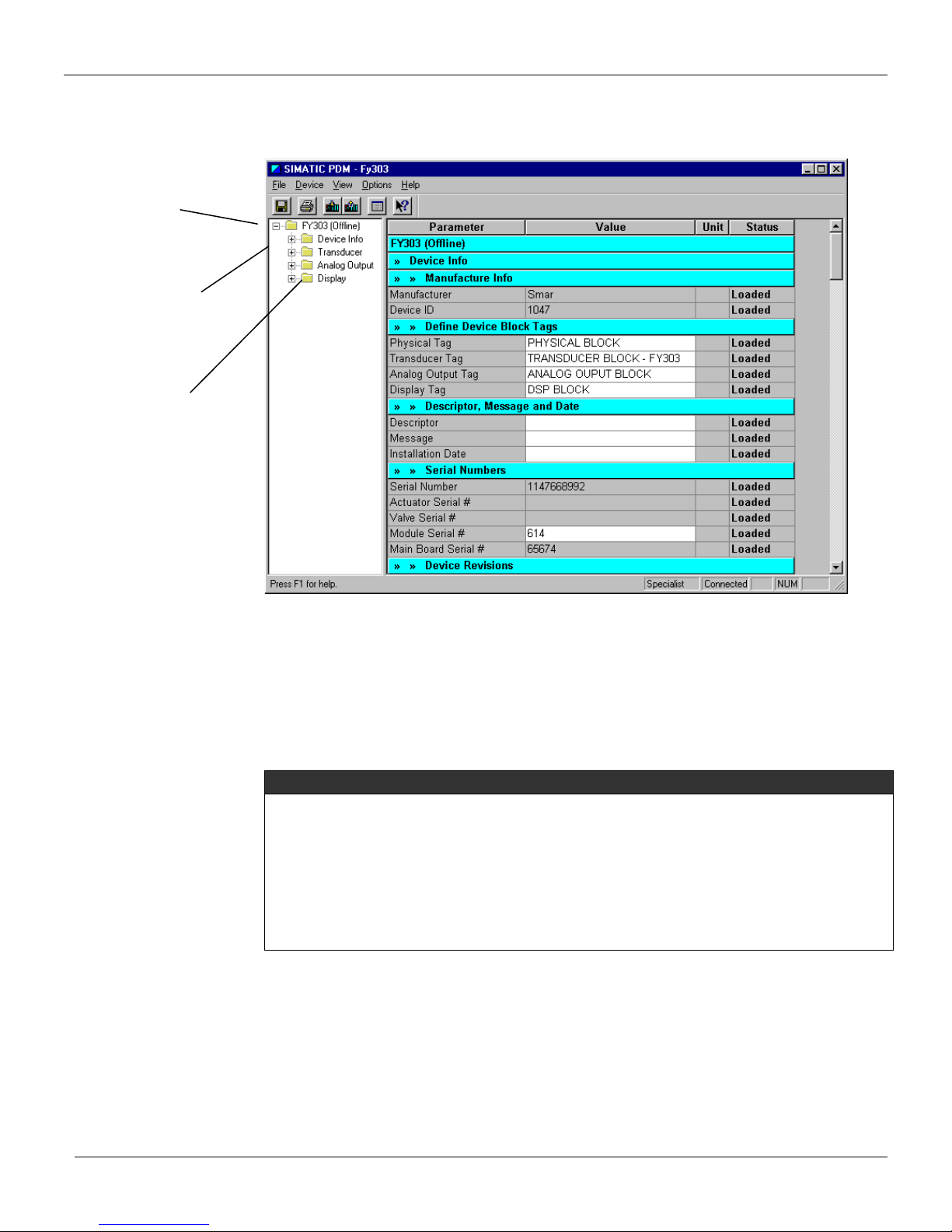
The device
Here, you can
As you can see
was created
as FY303.
see all blocks
instantiated.
the Transducer
and Display are
treated as
special type of
Function
Blocks, called
Transducer
Blocks.
Configuration
The Simatic PDM (Process Device Manager) configuration software from Siemens, for example,
can configure many parameters of the Input Transducer block.
Figure 3.1 - Function and Transducer Blocks
To make the configuration of Transducer Block, we need to select the menu "Device"
Use this menu:
- To change the device address;
- To make the up/download of parameters;
- To configure the Transducer Block, Analog Output Block and Display Block;
- To calibrate the positioner; made the Auto Setup
NOTE
Auto Setup procedure for FY303 positioner in ACP.
When the positioner FY303 is work i ng with a pneumatic cylindrical actuat or or a valve with high air inertia (slow
movem ent) and during the self calibration proc ess (SETUP) is gotten 40% permanently on the LCD, please
decrease the ACP_F value using the loc al adjustment. For this proposal, you need to configure the ACP _F
parameter on the LCD display, using the local adjustment. Enter into the local adjustment and select one of
LCDs (for example LCD_2), then select TRD block and adjust the PRMT parameter to 114 (relative index of
this parameter in the Transducer Block). Browse up to UPD parameter to update the local adjustment LCD
configuration. Reenter into the local adjustment and then browse up to ACP_F parameter where you can
decrease the value. For an initial step, you can decrease it to 60 and then browse up to SETUP parameter and
execute the self-calibration process setting this parameter to 2 (Initialize the self-calibration process).
To make the reset by software, to protect the device against writing and to simulate the value from
transducer block to analog output block;
Save and restore data calibration.
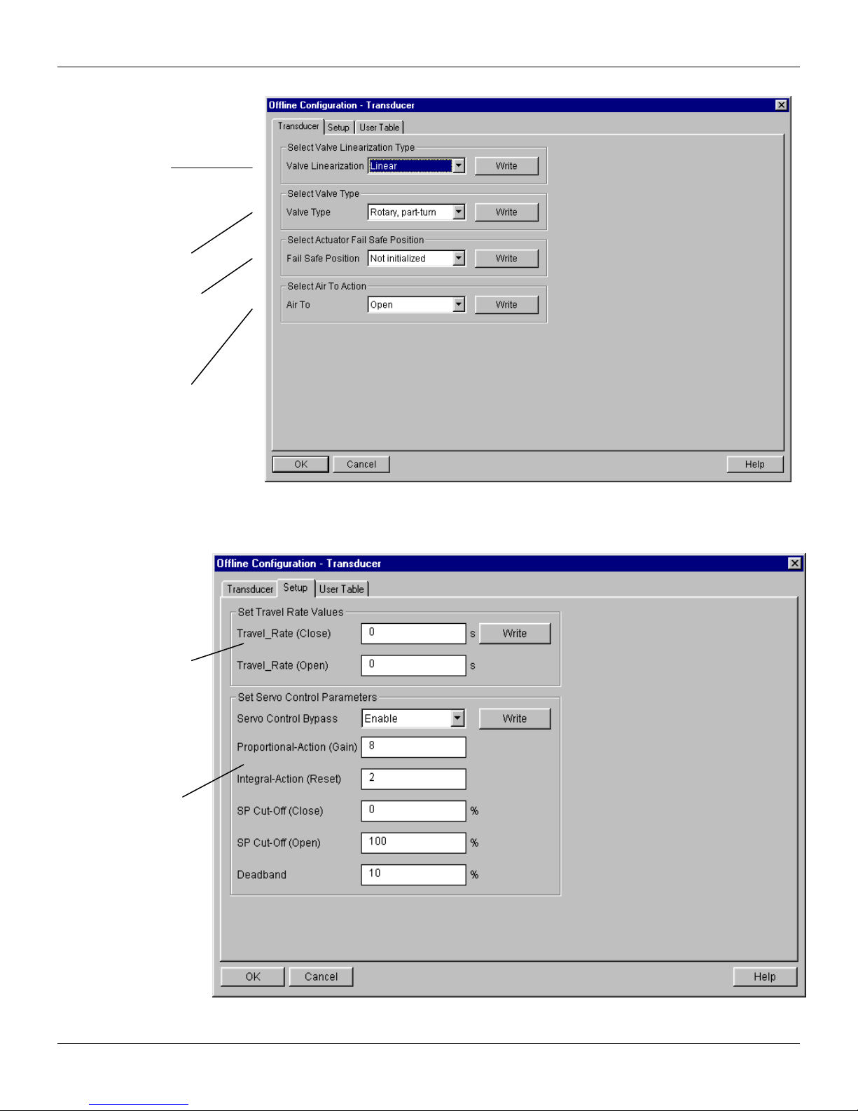
To make the configuration of Transducer Block, we need to select the menu: Device - Offline
Configuration - Transducer.
3.13
Page 40
FY303 – Operation, Maintenance and Instructions Manual
Servo Control
Te user can set air to
The user can
select the valve
linearization
type: linear,
user defined
(table), EP25,
EP33, EP50,
Q24, Q22,
EQ50.
The user can select
the valve type.
The actuator Fail action
can be: Opening
(100%), Closing (0%),
not initialized or none.
open or air to close
according to the action.
Configurable seconds to
full span change (closing
time of the valve) in
seconds and Configurable
seconds to full span
change (opening time of
the valve) in seconds.
Parameters:
The gain and reset
depend on valve type.
Figure 3.2 - Offline Configuration - Transducer
Selecting the page Setup, the user configures some data for the internal servo PID of FY303.
3.14
Figure 3.3 - Simatic PDM - Transducer Configuration Setup
Page 41
Configuration
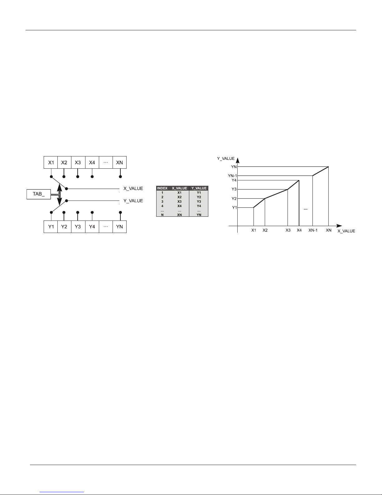
Table handling
There is the possibility to load and re-load tables in the devices. This table is used for linearization
mostly. For this procedure the following parameters are necessary:
TAB_INDEX
TAB_X_Y_VALUE
TAB_MIN_NUMBER
TAB_MAX_NUMBER
TAB_OP_CODE
TAB_STATUS
The TAB_X_Y_VALUE parameter contains the value couple of the each table entries.
To make the configuration of Transducer Block, we need to select the menu Device - Offline
Configuration -Transducer. The TAB_INDEX parameter identifies which element of the table is in
the X_Y_VALUE parameter currently (see the following figure).
Figure 3.4 - Parameters of a Table
TAB_MAX_NUMBER is the maximum size of the table in the device. TAB_MIN_NUMBER i s the
minimum size of the table in the device.
The modification of a table in the device influences the measurement algorithms of the device.
Therefore an indication of a starting and an endpoint is necessary. The TAB_OP_CODE controls
the transaction of the table. The device provides a plausibility check. The result of this check is
indicated in the TAB_STATUS parameter.
The User Table is used to make the position characterization in several points.
The user can configure up to 21 points in percentage.
The valve characteristic curve may be slightly nonlinear.
This eventual non-linearity may be corrected through the User Table.
The user just needs to configure the input values and the correspondent output values in %.
Configure a minimum of two points. These points will define the characterization curve. The
maximum number of points is 21. It is recommended to select the points equally distributed over the
desired range or over a part of the range where more accuracy is required. The user needs to set
"user defined (table) to valve linearization type.
3.15
Page 42
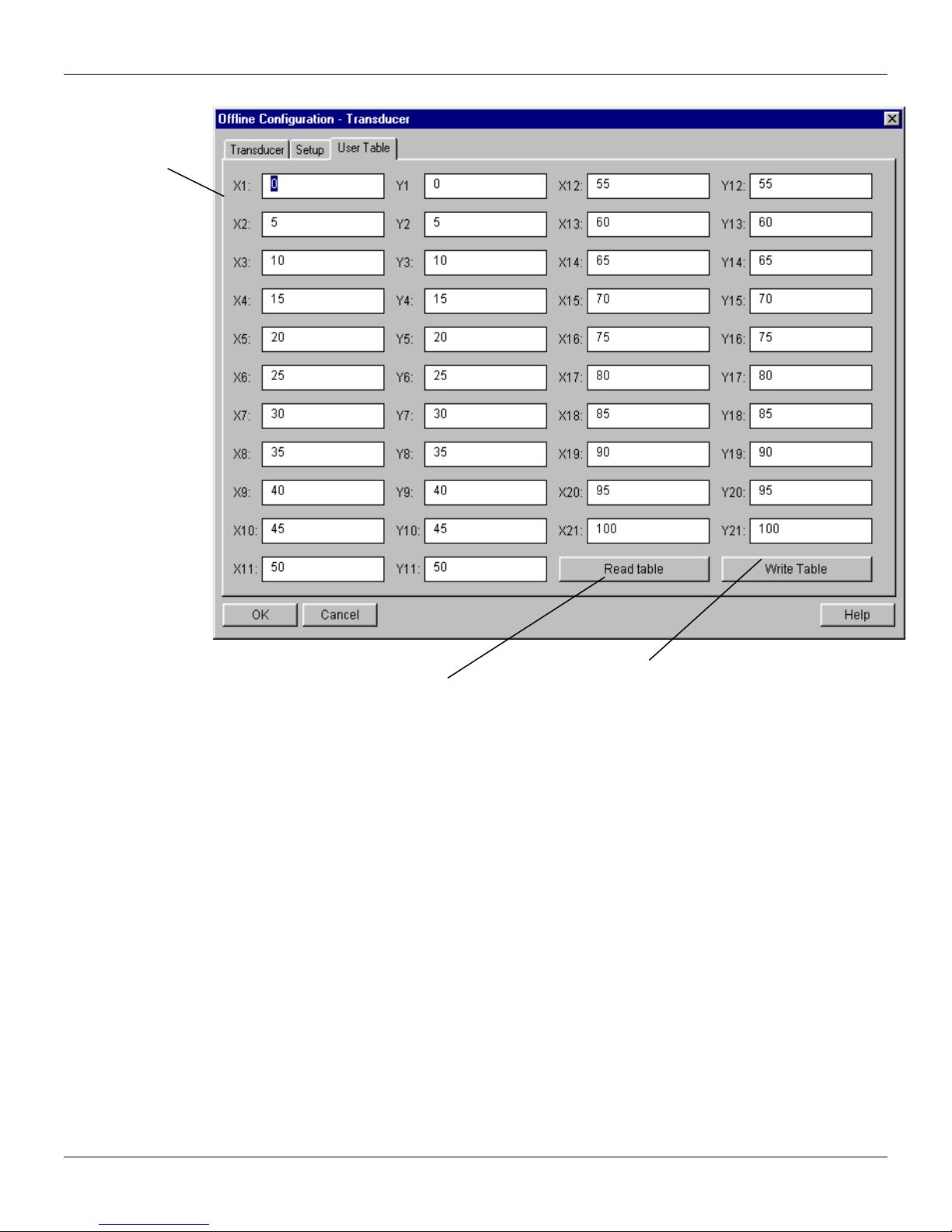
FY303 – Operation, Maintenance and Instructions Manual
Allows the reading of
After configuring the points, this key
Enter the input and
output values.
configurable table.
must be pressed to verify if the table
is monotonous increasing.
Figure 3.5 - FY303 Simatic PDM - Transducer Offline Configuration - User Table Screen
The desired flow characteristics may be changed using this function. E.g. If a valve with linear
inherent flow characteristic is used and equal percentage applied flow characteristic is selected, the
valve will be act as an equal percentage valve.
The adjacent number is the rangeability of the valve. The rangeability of the valve may be found in
the manufacturer's documentation. The options for applied flow characterization are: LINEAR,
TABLE, EP25, EP33, EP50, QO25, QO33, and QO50
The equation resulting from its curve is:
Y (%) = (X/ (((X (%). /100)*(1-L)) +L)),
Where:
Y [%] = Value after the flow characterization curve calculation and X [%] = Position value before
entering in the curve calculation.
L = Characterization Factor
3.16
Page 43
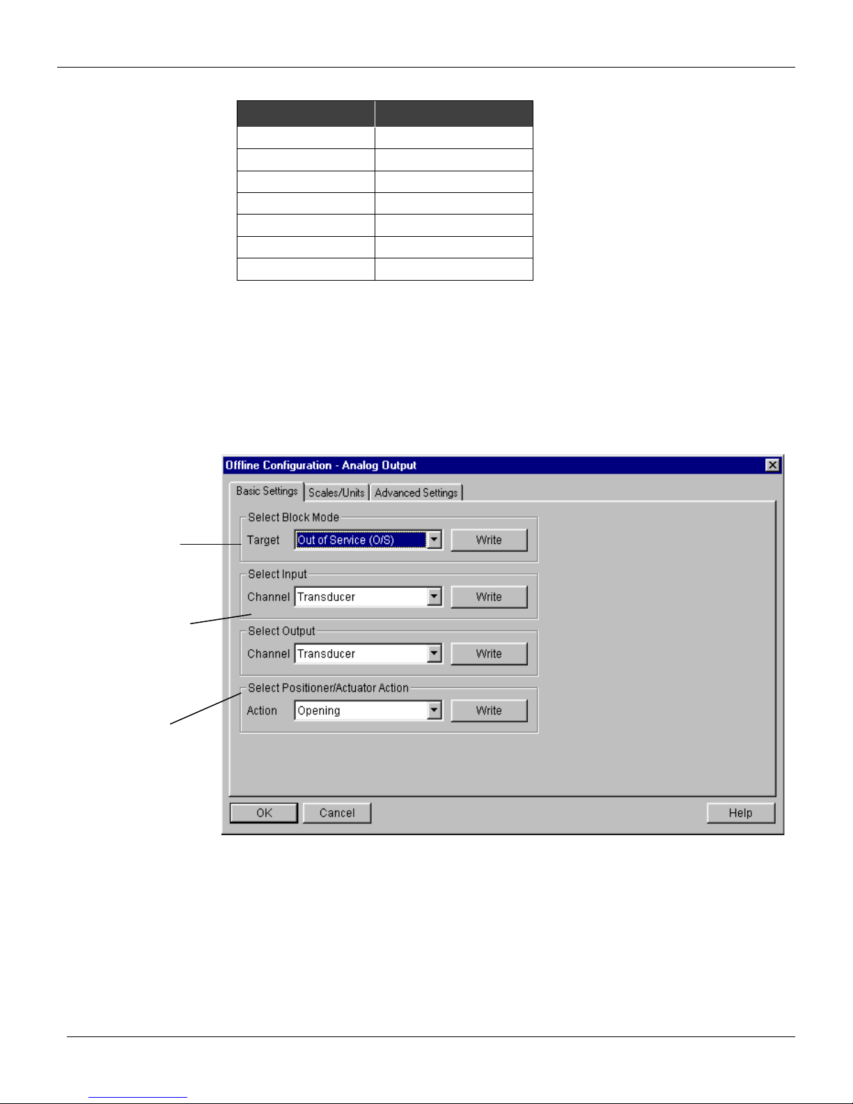
The user can set
The user needs to set
The user can set
TIPO L
LINEAR 1.0
EP25 3.5
EP33 4.1
EP50 5.1
QO25 0.27
QO33 0.24
QO50 0.19
How to Configure the Analog Out put Bl oc k
The AO block provides a value to an output transducer block. It provides value, scaling conversion,
Fail safe mechanism and other features.
The Analog Output Block is a function block used by devices that work as output elements in a
control loop, like valves, actuators, positioners, etc. The AO block receives a signal from another
function block and passes its results to an output transducer block through an internal channel
reference.
Configuration
the operation mode.
both channel to
transducer.
opening or closing for
the actuator action.
Figure 3.6 - FY303 Simatic PDM - Analog Output Block - Basic Settings - Offline Configuration
3.17
Page 44
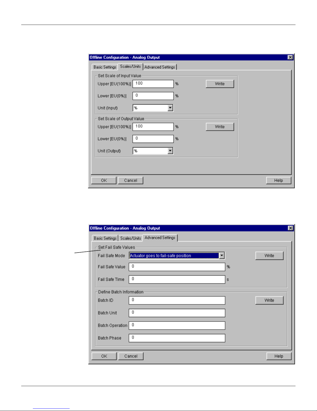
FY303 – Operation, Maintenance and Instructions Manual
Selecting the page Scale/Units, the user has the option to configure the scale and unit for the input
and output:
For Fail Safe mode the
options can be:
Actuator goes to failsafe position, storing
last valid setpoint and
fail safe value is used
as a control regulator
input.
Figure 3.7 - FY303 Simatic PDM - Analog Output Block - Scale/Units - Offline Configuration
The unit and scale for the output will be the same for the transducer block. Note that the allowed
units are %, rad, °, mm.
Selecting Advanced Settings page, the user can set the fail safe conditions.
Figure 3.8 - FY303 Simatic PDM - Analog Output Block - Advanced Settings - Offline
3.18
Configuration
Page 45
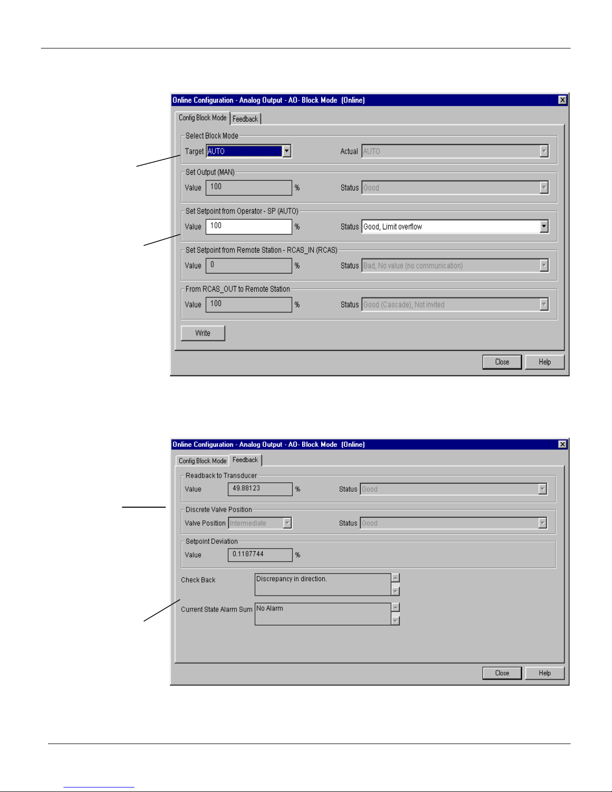
Information about
The user can set the
block mode operation.
According to the block
Configuration
In terms of online configuration, the user can select at the device menu the Online Configuration for
Analog Output block:
mode, the user can set
the setpoint.
the real condition
of transducer and
analog output
block.
Figure 3.9 - FY303 Simatic PDM - Online Configuration Mode Block for AO
Using Feedback page, the user can monitor and check all values related between the analog block
and the transducer block:
Check back and alarm
condition.
Figure 3.10 - FY303 Simatic PDM - Online Configuration Feedback for AO
3.19
Page 46
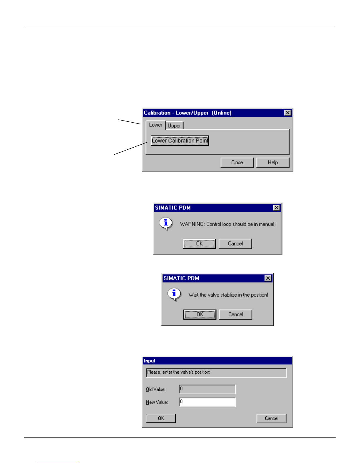
FY303 – Operation, Maintenance and Instructions Manual
The user can select
To start the lower
Position Calibration
First of all the user should configure the valve type, the servo gain according to the valve. Please,
see transducer offline configuration. In general, when the valve is fast, is appropriate to set a gain
value about 8. If the valve is slow, is appropriate to set a gain value about 43. It depends on case by
case and the valve type.
Then using the Device menu, the user must select Calibration, where we have the options:
"Lower/Upper", "Self-Calibration" and "Temperature".
Choosing "Lower/Upper" the user has the window:
lower or upper
calibration.
calibration procedure.
Figure 3.11 - FY303 - Simatic PDM Calibration Lower/Upper
After pressing "Lower Calibration Point", we get a warning:
If the user proceeds, the valve position goes to the lower position and we have the message:
If the valve is stabilized, when the user press "OK", we have a new window that allows him to enter
the desired value for the new calibrated point for the lower position. Write 0% in new value. For
FY303 it should be always 0%:
3.20
Page 47
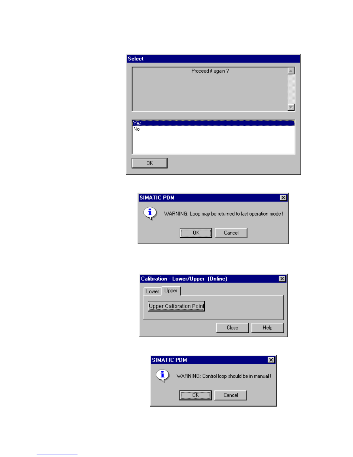
Configuration
After entering the desired valve, the position is corrected according to the desired value and the
user can make the correction until the right position is reached:
If the calibrated position is correct, press "No" and a new warning appears:
After user confirmation, the positioner comes to the normal operation.
The upper calibration procedure is similar than the lower:
After pressing "Upper Calibration Point", we get a warning:
3.21
Page 48
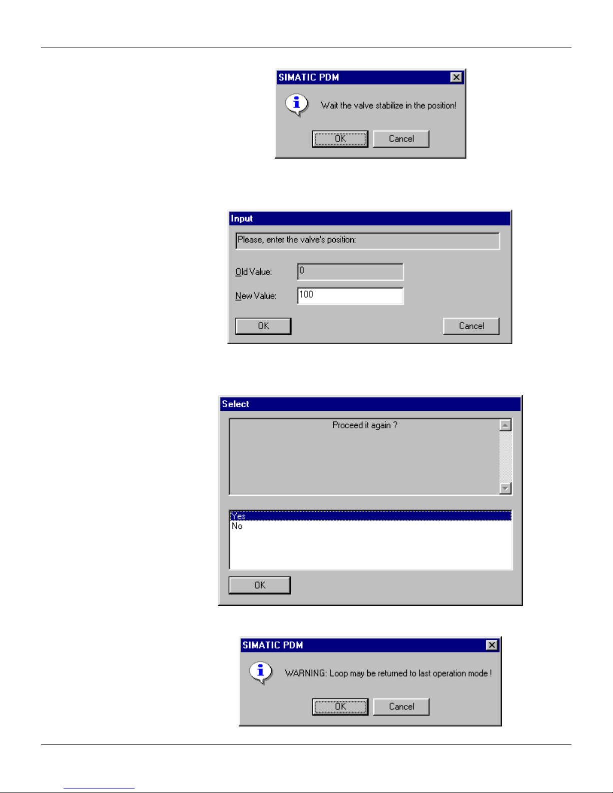
FY303 – Operation, Maintenance and Instructions Manual
If the user proceeds, the valve position goes to the upper position and we have the message:
If the valve is stabilized, when the user press "OK", we have a new window that allows him to enter
the desired value for the new calibrated point for the upper position. Write 100% in new value. For
FY303 it should be always 100%:
After entering the desired valve, the position is corrected according to the desired value and the
user can make the correction until the right position is reached:
If the calibrated position is correct, press "No" and a new warning appears:
3.22
Page 49
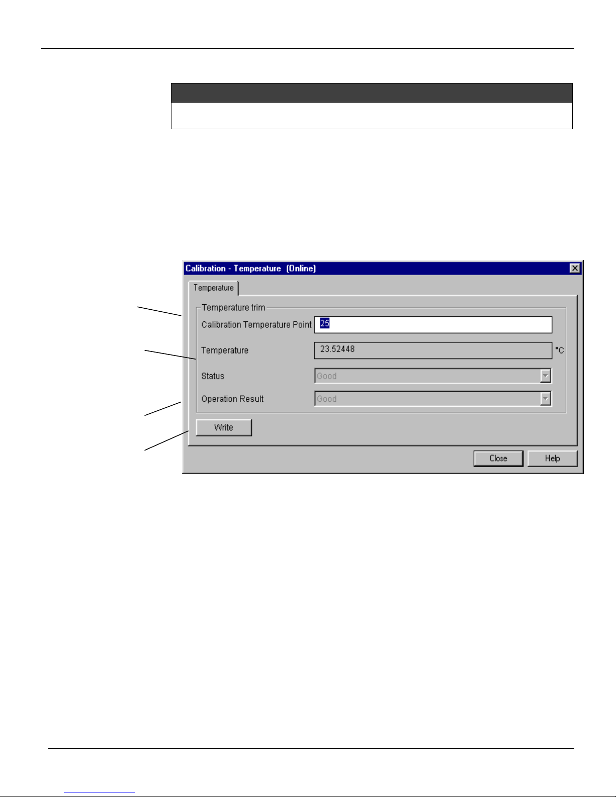
After user confirmation, the positioner comes to the normal operation.
The user can set the
The calibration unit is always percentage (%). I t is also recommendable, before a new calibrat ion, to save the
existing trim data by means of parameter BACKUP_RESTORE, using the option "Last Cal Backup".
Temperature Calibrat ion
The parameter CAL_TEMPERATURE can be used to trim the temperature sensor located at the
body of positioner in order to improve the accuracy of temperature measurement done by its sensor.
The range accepts from - 40°C to + 85 °C. The parameter SECONDARY_VALUE indicates the
value of such measurement.
Using the Simatic PDM, go to the Device menu and select the "Calibration" menu and then
"Temperature:
desired calibration
temperature point.
Here, the final calibrated
temperature can be
checked.
The user can check the
operation result.
To calibrate, press the key
"write".
Configuration
NOTE
Figure 3.12 - FY303 Temperature Calibration
3.23
Page 50
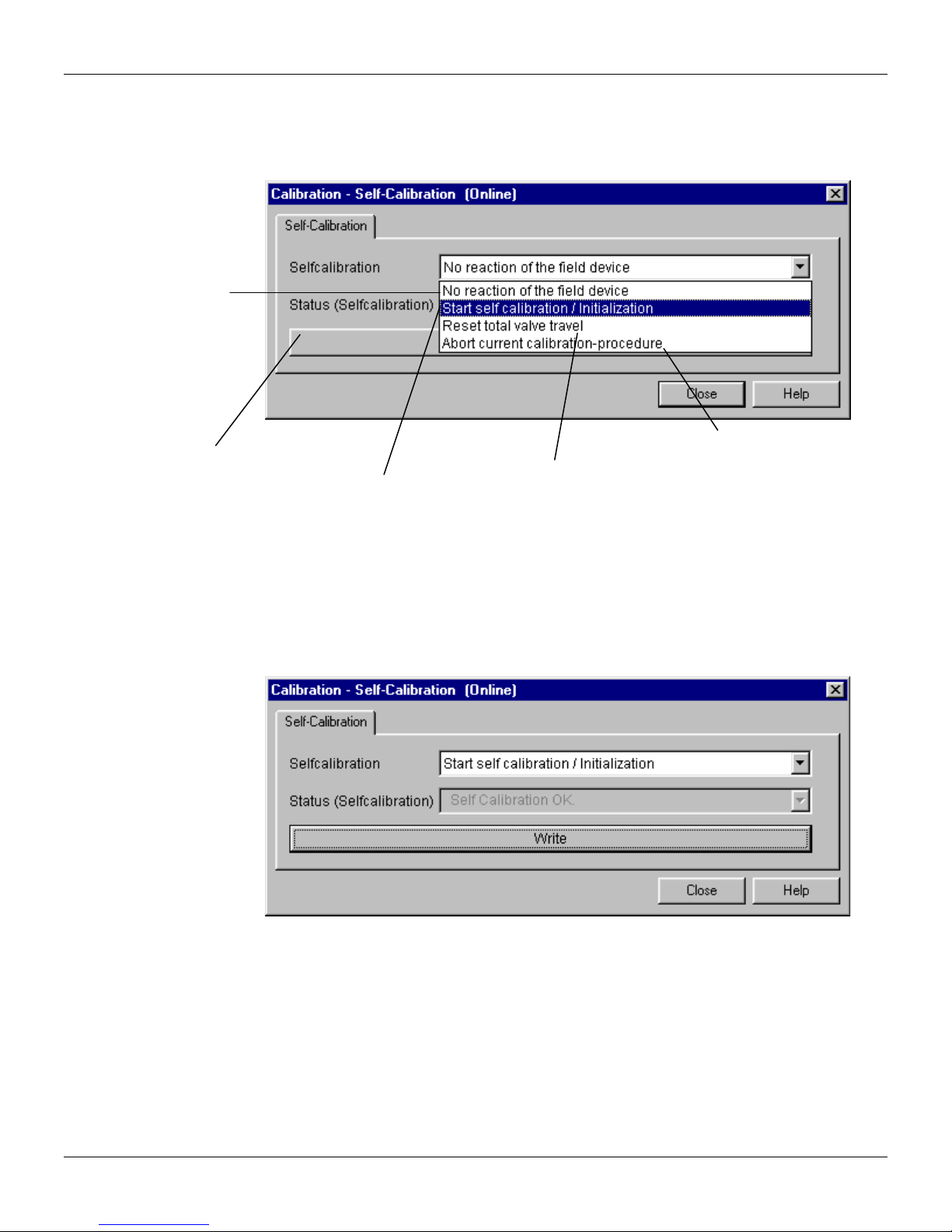
FY303 – Operation, Maintenance and Instructions Manual
In normal operation, we
This marked option allows
After selecting the self-calibration
To abort the self-
select this option.
To reset the total valve
Self-Calibration
Using the "Self-Calibration" procedure, the user starts a method of self-calibration for the positioner.
For this reason, the option "Start self calibration/Initialization" should be selected at the window
below. The self-calibration can take some minutes according to the valve:
have this option indicating
no reaction of the field
device according to the
self-calibration procedure.
procedure, please, press the "Write"
key to begin the procedure.
calibration procedure,
the start of self-calibration
procedure.
travel, select this option.
After selecting the s elf-calibration procedure, the positioner will move the valve during some time to
setup the lower and upper position automatically. At LCD interface, the user can see the steps of
this procedure in %.
If the procedure gets success we got the following stat us of "Self Cal i bration OK”.
We can have the following options for the status calibration:
- Self Calibration OK
- Aborted
- No magnet part detected
- Error in mechanical system
- Timeout
- Pressure Problem
3.24
Page 51
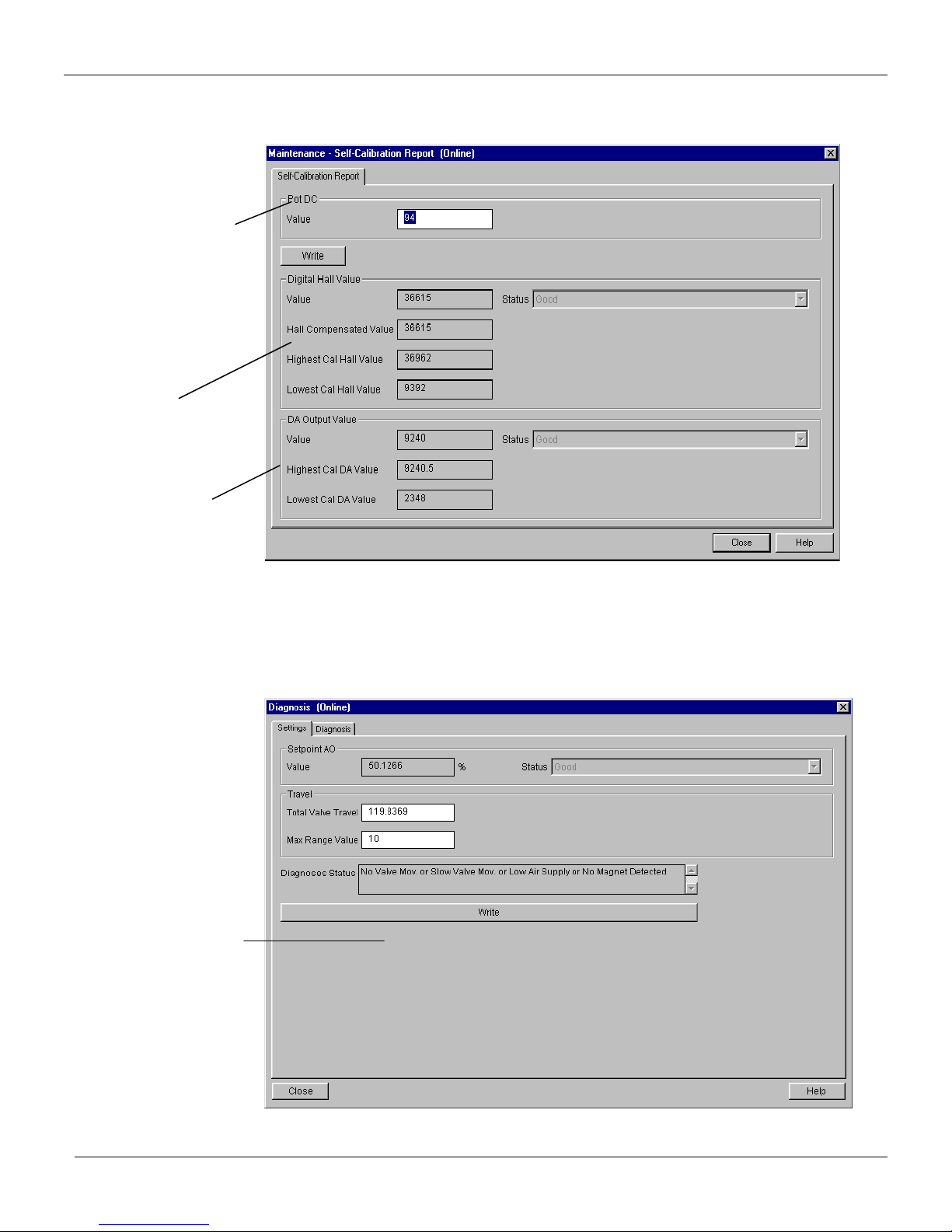
This value describes the
set value for hardware
The user can see:
compensation. It is an
automatic calculated
value. It is suitable that
the user does not change
this value.
The Hall sensor
value and the
calibrated
points for it.
The value for the DA
converter and the
calibrated points for it.
Configuration
To verify and check the self calibration results the user should select at the main menu the option
"Maintenance Self-Calibr at ion Repor t":
Diagnosis
the setpoint value from
AO; the total valve travel
according to the
maximum range value for
the valve; and a general
status for FY303.
Figure 3.13 - FY303 Maintenance Self-Calibration Report
Using the "View" menu and selecting "Diagnosis", the user has accessing to the diagnosis windows,
according to the window below:
Figure 3.14 - FY303 Settings
3.25
Page 52
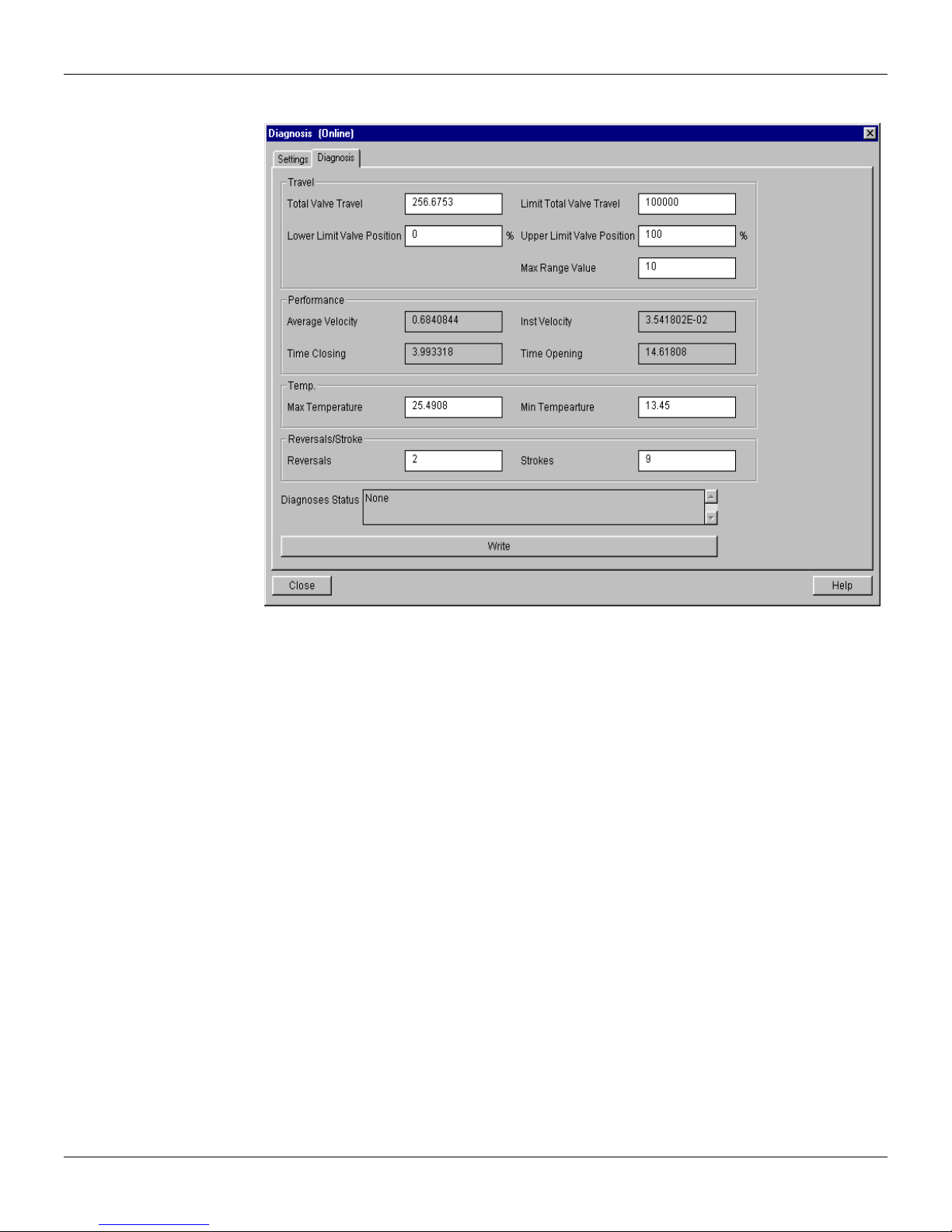
FY303 – Operation, Maintenance and Instructions Manual
Selecting the "Diagnosis" page, we have:
Using this window, the user can have some items for diagnosing:
- Travel: according to the maximum range valve value, we have the total valve travel and a
generation of traveling Limit Exceeded when this value is higher than limit total valve travel
parameter;
- Performance: the user can verify the average velocity, the instantaneous velocity, the time
closing (when the direction is from 100.0% to 0.0%) and the time opening (when the direction is
from 0.0% to 100.0%). These times are according to the configured rate for closing and opening.
- Temp: The user can verify the maximum and minimum temperature;
- Reversals/stroke: we have the possibility to verify both values according to the movement of
valve.
Some factors are important to the performance of movement:
- the air pressure;
- the proportional action (servo gain);
- the integral action (reset);
- the travel rate for closing and opening.
Transducer Display - Configuration
Using the Simatic PDM or any other configuration tool is possible to configure the Display
Transducer block. As the name described it is a transducer due the interfacing of its block with th e
LCD hardware.
The Transducer Display is treated as a normal block by any configuration tool. It means, this block
has some parameters and those ones can be configured according to customer's needs.
Figure 3.15 - FY303 Diagnosis
3.26
Page 53
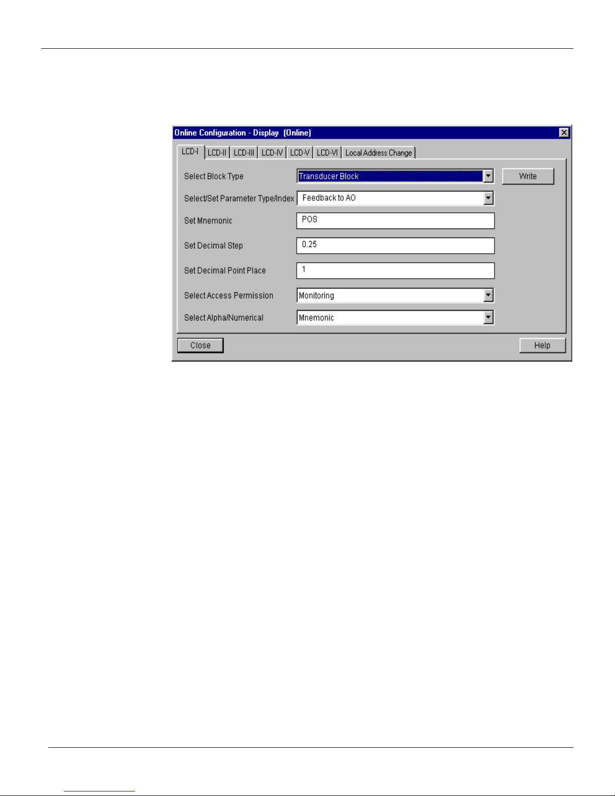
Configuration
The customer can choose up to six parameters to be shown at LCD display; they can be parameters
just for monitoring purpose or for acting locally in the field devices by using a magnetic tool. The
seventh parameter is used to access the physical device address. The user can change this
address according to his application. To access and configure the Display Block, please, go to the
main menu, select "Device Online Configuration - Display Block":
Display Transducer Block
The local adjustment is completely configured by Simatic PDM or any configuration tool. It means,
the user can select the best options to fit his application. From factory, it is configured with the
options to set the Upper and Lower trim, for monitoring the input transducer output and check th e
Tag. Normally, the transmitter is much better configured by Simatic PDM or configuration tool, but
the local functionality of the LCD permits an easy and fast action on certain parameters, since it
does not rely on communication and network wiring connections. Among the possibilities by Local
Adjustment, the following options can be emphasized: Mode block, Outputs monitoring, Tag
visualization and Tuning Parameters setting.
The interface between the users is described very detailed on "Programming Using Local
Adjustment". It is significantly the resources on this transducer display, also all the Series 303 field
devices from Smar has the same methodology to handle with it. So, since the user has learned
once, he is capable to handle all kind of field devices from Smar.
All function blocks and transducers defined according Profibus PA have a description of their
features written by the Device Description Language.
This feature permits that third party configuration tools enabled by Device Description Service
technology can interpret these features and make them accessible to configure. The Function
Blocks and Transducers of Series 303 have been defined rigorously according the Profibus PA
specifications in order to be interoperable to other parties.
In order to able the local adjustment using the magnetic tool, it is necessary to previously prepare
the parameters related with this operation via System Configuration.
There are six groups of parameters, which may be pre-configured by the user in order to able, a
possible configuration by means of the local adjustment. As an example, let’s suppose that you
don’t want to show some parameters; in this case, simply select "None" in the parameter, "Select
Block Type". Doing this, the device will not take the parameters related (indexed) to its Block as a
valid parameter.
Figure 3.16 – Display Block and Simatic PDM
3.27
Page 54
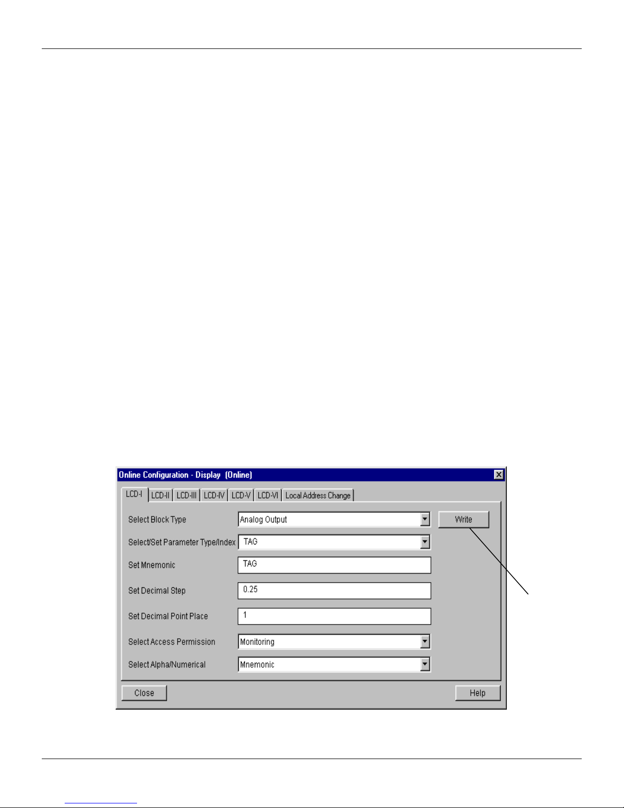
FY303 – Operation, Maintenance and Instructions Manual
The option
Definition of Parameters and Values
Select Block Type
This is the type of the block where the parameter is located. The user can choose: Transducer
Block, Analog Output Block, Physical Block or None.
Select / Set Parameter Type / Index
This is the index related to the parameter to be actuated or viewed (0, 1, 2…). For each block there
are some pre-defined indexes. Refer to the Function Blocks Manual to know the desired indexes
and then just enter the desired index.
Set Mnemonic
This is the mnemonic for the parameter identification (it accepts a maximum of 16 characters in the
alphanumeric field of the display). Choose the mnemonic, preferably with no more than 5 characters
because, this way, it will not be necessary to rotate it on the display.
Set Decimal Step
It is the increment and decrement in decimal units when the parameter is Float or Float Status
value, or integer, when the parameter is in whole units.
Set Decimal Point Place
This is the number of digits after the decimal point (0 to 3 decimal digits).
Set Access Permission
The access allows the user to read, in the case of the “Monitoring” option, and to write when "action"
option is selected, then the display will show the increment and decrement arrows.
Set Alpha Numerical
These parameters include two options: value and mnemonic. In option value, it is possible to display
data both in the alphanumeric and in the numeric fields; this way, in the case of a data higher than
10000, it will be shown in the alphanumeric field.
In option mnemonic, the display may show the data in the numeric field and the mnemonic in the
alphanumeric field.
For devices where the software version is higher or equal to 1.10, please see the “Programming
Using Local Adjustment”, in the Installation, Operation and Maintenance Procedures Manual.
In case you wish to visualize a certain tag, opt for the index relative equal to "tag". To configure
other parameters just select "LCD-II" up to "LCD-VI" windows:
Figure 3.17 - Parameters for Local Adjustment Configuration
3.28
"Write" should
be selected in
order to
execute the
upgrade of local
adjustment
programming
tree.
Page 55
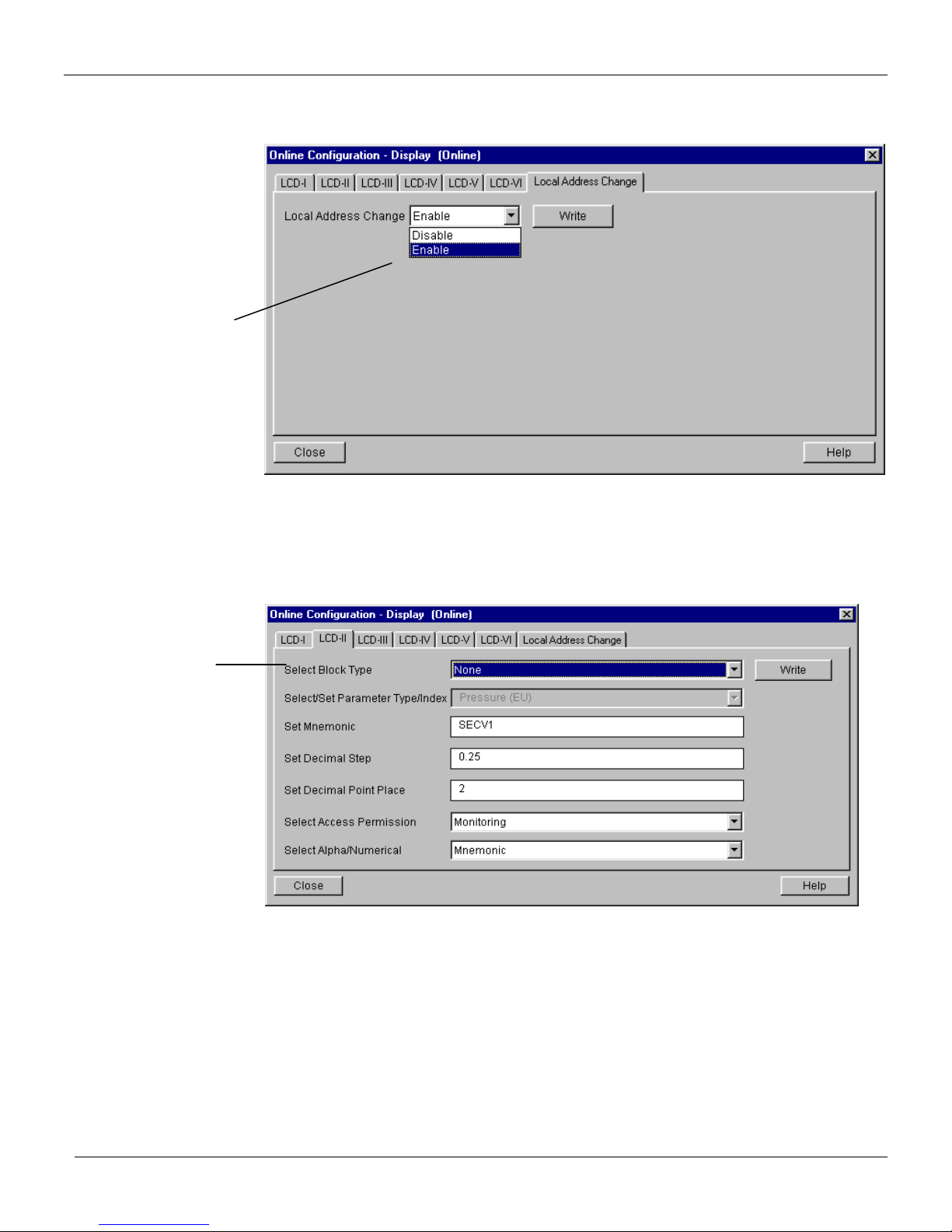
When the option
Selecting
"enable" is selected,
the user can
change the physical
device address.
Configuration
The window "Local Address Change" allows the user "enable/disable” access to changing the
physical device address.
Figure 3.18 - Parameters for Local Address Configuration
When the user enter into the local adjustment and rotate the parameters using the magnetic tool,
after escaping to normal operation, e.g., the monitoring, if the parameter when the magnetic tool is
removed has "Access Permission equal to "monitoring", then this last parameter will be shown at the
LCD.
"None", only the
last chosen
monitoring
parameter will
be shown at
LCD.
F
Figure 3.19 - Parameters for Local Adjustment Configuration
Always on the LCD interface will be shown two parameters at the same time, switching between the
configured parameter at the LCD-II and the last monitoring parameter. If the user does not want to
show two parameters at the same time, it is only necessary to opt for "none" when configure the
LCD-II:
3.29
Page 56
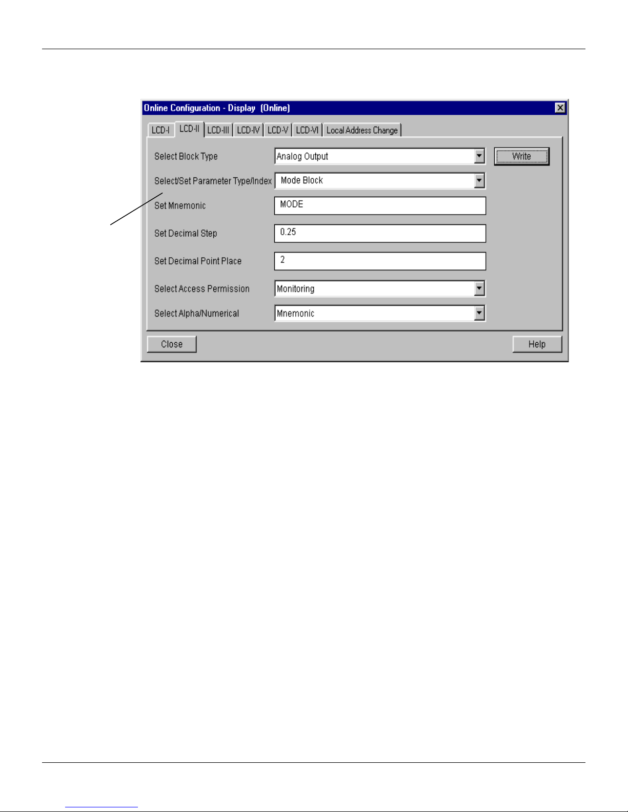
FY303 – Operation, Maintenance and Instructions Manual
With this option,
The user can select the "Mode Block" parameter at the LCD. In this case is necessary to select the
index equal to "Mode Block":
the Mode Block
parameter is
shown at the
LCD.
Calibrating using Local Adjustment
3.30
Figure 3.20 - Parameters for Local Adjustment Configuration
The positioner has two holes for magnetic switches, located under the identification plate (See the
section "Programming Using Local Adjustment"). These magnetic switches are activated by one
magnetic tool.
This magnetic tool enables adjustment of the most important parameters of the blocks. It also
enables pre-configuration of the communication.
The jumper J1 on top of the main circuit board must be in place and the positioner must be fitted
with the digital display for access to the local adjustment. Without the display the local adjustment is
not possible.
In order to enter the local adjustment mode, place the magnetic tool in orifice “Z” until flag “MD”
lights up in the display. Removes magnetic tool from “Z” and place it in orifice “S”. Remove and
reinsert the magnetic tool in “S” until the message “LOC ADJ” is displayed.
The message will be displayed during approximately 5 seconds after the user removes the magnetic
tool from “S”. By placing the magnetic tool in “Z” the user will be able to access the local
adjustment/monitoring tree.
Browse to parameter “LOPOS”. After that in order to start the calibration, the user shall activate
parameter “LOPOS” with the help of the magnetic tool placed in “S”. For example, it is possible to
enter 0%. When the magnetic tool is removed from “S”, the output will be set to a value close to the
desired value. The user shall then browse the tree up to parameter FEED (FEEDBACK_CAL), and
actuate this parameter by placing the magnetic tool in “S” until reaching the value obtained from the
position reference.
The user shall continue to write in this parameter until it reads 0% or the desired lower position
value. Browse to parameter “UPPOS”. After that, in order to start the calibration, the user shall
actuate parameter “UPPOS” by placing the magnetic tool in “S”. For example, it is possible to enter
100%. When the magnetic tool is removed from “S”, the output will be set to a value close to the
desired value. The user shall them browse the tree up to parameter FEED (FEEDBACK_CAL), and
actuate this parameter by placing the magnetic tool in “S” until reaching the desired value.
Page 57
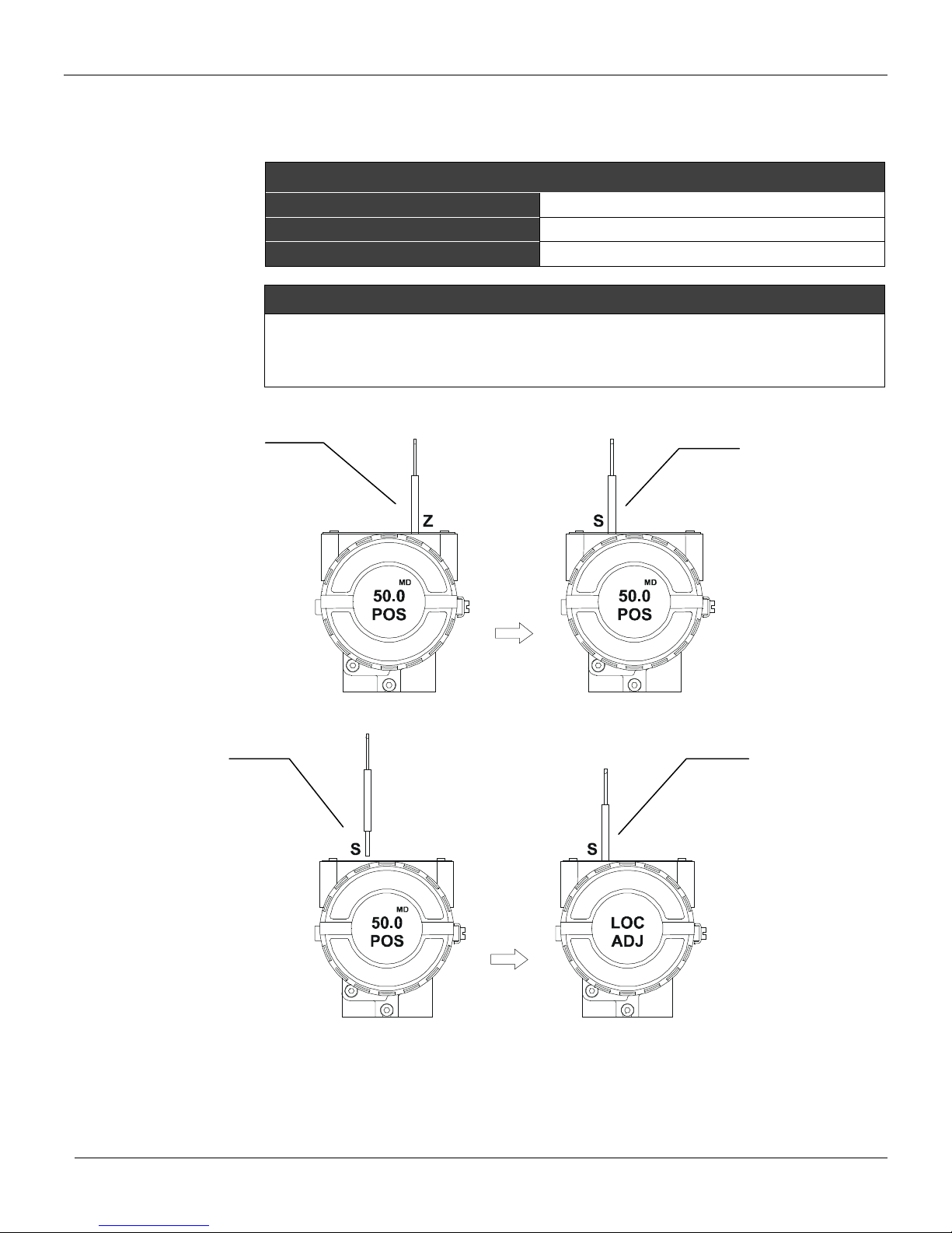
Configuration
Codes for XD_ERROR:
Place the
In order to start the
Insert the magnetic
Remove the
The user shall write in this parameter until it reads 100% or the desired upper position value.
The LOWER and UPPER should be different.
LIMIT CONDITIONS OF CALIBRATION
LOPOS (Lower Position)
UPPOS (Upper Position)
FEED
16: Default Value Set
22: Out of Range
26: Invalid Calibration Request
27: Excessive Correction
Programming using Local Adjus t ment
local adjustment,
place the magnetic
tool in orifice Z and
wait until letters MD
are displayed.
Always equal 0%
Always equal 100%
- 10% =< FEED =< 110%, otherwise XD_ERROR = 22
NOTE
magnetic tool in
orifice S and wait
during 5 seconds.
magnetic tool
from orifice S.
Figure 3.23 - Step 1 - FY303
tool in orifice S
once more and
LOC ADJ should be
displayed.
Figure 3.24 - Step 2 – FY303
3.31
Page 58
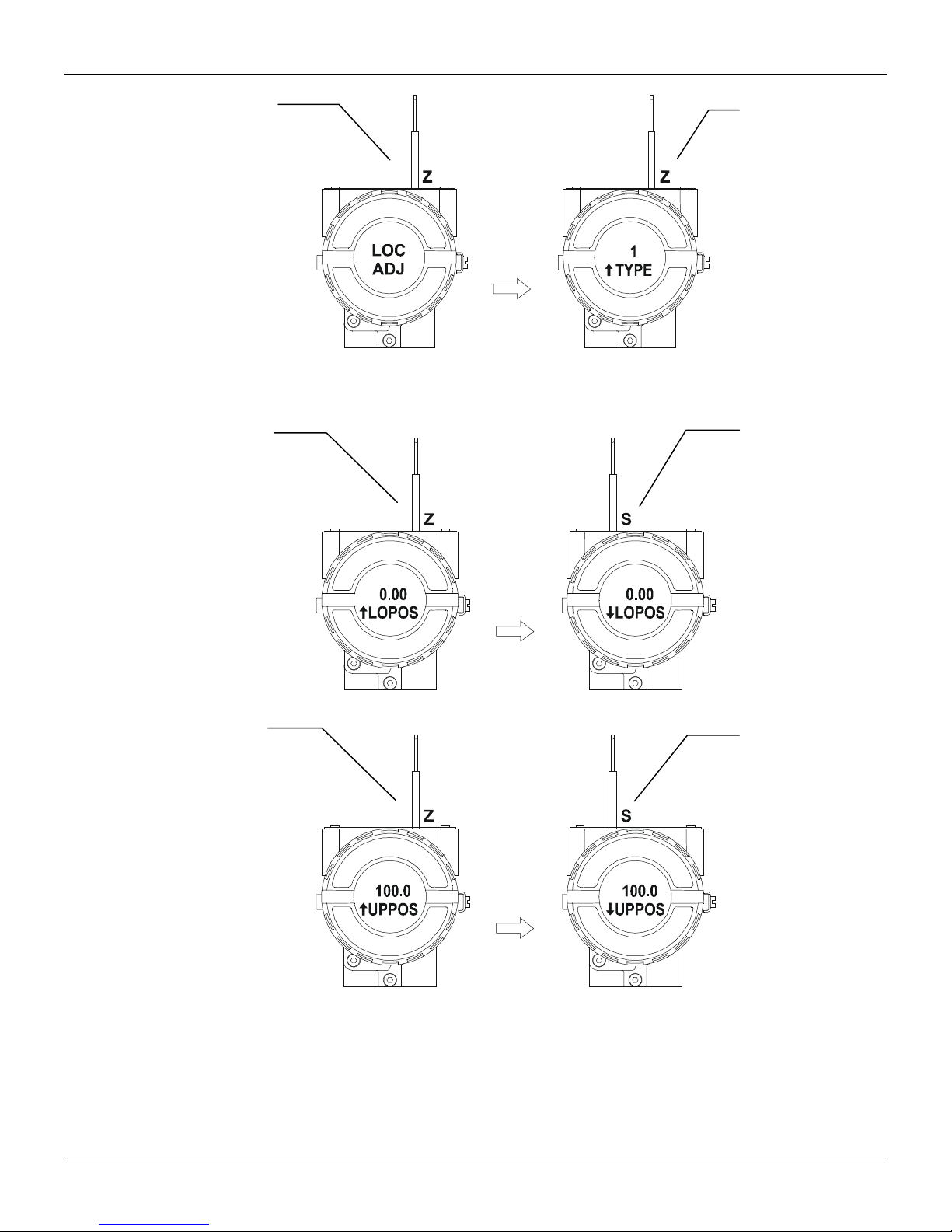
FY303 – Operation, Maintenance and Instructions Manual
Place the magnetic
In order to start the
In order to
S.
In order to
tool in orifice Z. In
case this is the first
configuration, the
option shown on the
display is the TAG
with its corresponding
mnemonic configured
by the Configuration
Tool. Otherwise, the
option shown on the
display will be the one
configured in the prior
operation. By keeping
the tool inserted in
this orifice, the local
adjustment menu will
rotate.
LOPOS, simply insert
the magnetic tool in
orifice S as soon as
LOPOS is shown on
the display. An arrow
pointing upward (-)
increments the valve
and an arrow
pointing downward
(¯) decrements the
valve. In order to
increment the lower
position valve, keep
the tool inserted in S.
In this option TYPE,
is indicated by the
numbers 1 or 2,
which respectively
represent Linear or
Rotary valves.
Figure 3.25 - Step 3 - FY303
decrement the
lower position
valve, place the
magnetic tool in
orifice Z to shift
the arrow to the
downward
position and then,
by inserting and
keeping the tool
in orifice S, it is
possible to
decrement the
lower position
valve.
In order to start the
UPPOS, simply
insert the magnetic
tool in orifice S as
soon as UPPOS is
shown on the
display. An arrow
pointing upward (-)
increments the
valve and an arrow
pointing downward
(¯) decrements the
valve. In order to
increment the upper
position valve, keep
the tool inserted in
Figure 3.26 - Step 4 – FY303
decrement the
upper position
valve, place the
magnetic tool in
orifice Z to shift the
arrow to the
downward position
an then, by
insetting and
keeping the tool in
orifice S, it is
possible to
decrement upper
position valve.
Figure 3.27 - Step 5 – FY303
3.32
Page 59
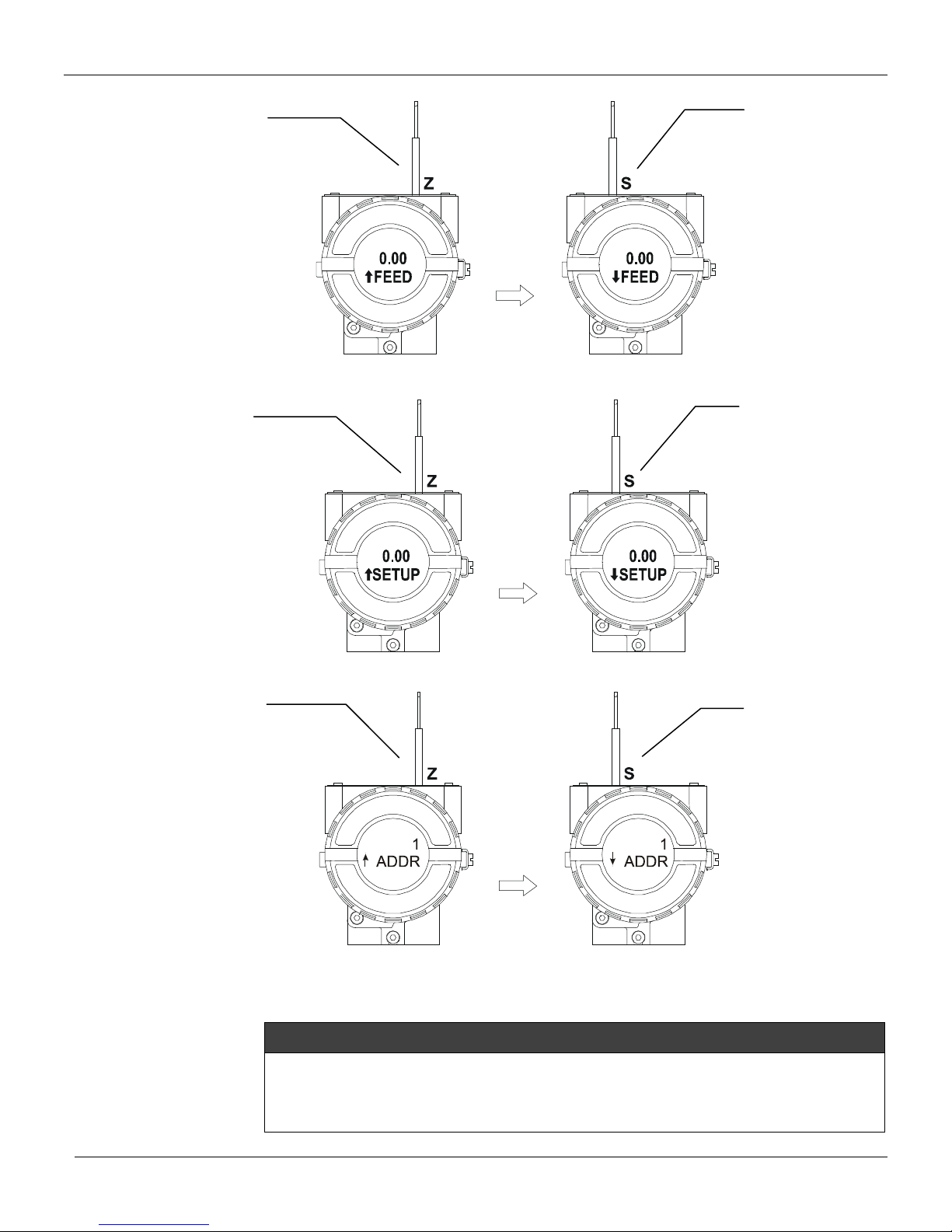
Configuration
Place the
Insert the magnetic
This option
a) In order to
↑
↓
b) In order to
Option FEED allows
the user to correct
the valve
calibration. In order
to implement the
correction, read the
valve indicated by
the valve and enter
it in this option. This
option makes it
possible to correct
LOPOS as well as
UPPOS. An arrow
pointing upward
increments the
position valve.
implements the
auto setup of the
valve, that is, the
lower and upper
position points of
the valve. When
setup displays 0
(zero), it indicates
that the setup is
disabled.
magnetic tool in
orifice S to shift
the arrow to the
downward position
and decrement the
calibration valve in
accordance with
the valve readout
valve. An arrow
pointing downward
decrements the
position valve.
Figure 3.28 - Step 6 - FY303
tool in orifice S and
enter the value 2.
After this, the auto
setup will be started
and a flashing
message with the
word SETUP will
show in the display
of the positioner.
After this process
finishes, the local
adjustment returns
to normal operation.
change the address
value, simply take
off the magnetic
tool from orifice Z
as soon as ADDR
is shown on the
display. An arrow
pointing upward (
increments the
address and an
arrow pointing
downward (
decrements the
address. In order to
increment the
address, insert the
tool in S up to set
the value desired.
)
)
Every time the Self Calibration is used it is suitable to save it via configuration tool, and to write in the
Backup-Restore parameter of the transducer block the sensor Data Backup option.
This Local adjustment configuration is a suggesti on onl y. The user may choose his preferred configuration via
configuration tool, simply configuring the display block. (refer to paragraph Display Transducer Block )
Figure 3.29 - Step 7 - FY303
decrement the
address value,
place the magnetic
tool in orifice Z to
shift the arrow to
the downward
position and then,
by inserting and
keeping the tool in
orifice S, it is
possible to
decrement the
address value.
Figure 3.30 - Step 8 - FY303
NOTE
3.33
Page 60
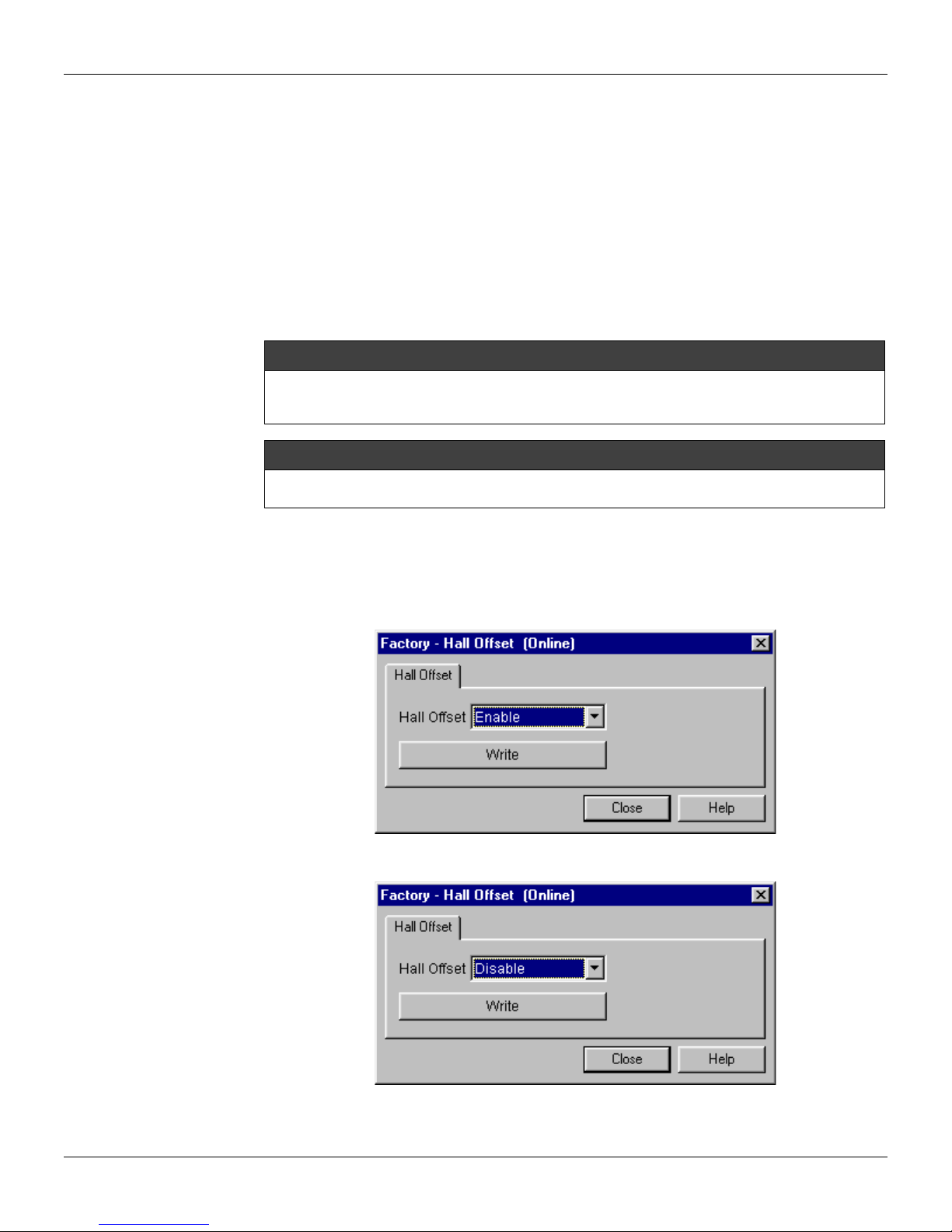
FY303 – Operation, Maintenance and Instructions Manual
Self-Calibration using Loca l Adjustment
This process is necessary to find the position values at which the valve is considered fully open or
close. This operation can be done using the Configuration Tool or the Local Adjustment. The
FY303 automatically finds the fully open and closed positions of a valve, but the user may also set a
narrower range of operation should he like to. Before making the Auto-Setup, select the type of
valve through the parameter VALVE_TYPE choosing between "Linear or Rotary" options.
The setup operation can be started writing "Enable" (2) on the parameter SETUP, so the positioner
will execute immediately the operation of auto-setup for approximately 2 to 5 minutes depending on
the type of valve, other configured parameters and function blocks used in the positioner.
The process will be finished when the SETUP parameter will indicate "Disable" (0) automatically
during the operation of reading.
NOTE
This operation should be performed off-li ne or with the process shut down to be sure that the plant operation
is not disturbed, due the valve will be moved between the fully open and close points i n order to reach the
better adjustment.
In case of oscillation, decrease the gain of valve, acting on the SERVO GAIN parameter.
If the valve could be out-of-control after its operation, please, repeat the Self-Calibration operation again.
NOTE
Hall's Offset Compensation without Magnet Part
Before installing the magnet to the positioner, write "Enable" on the menu Factory Hall Offset at
Device menu and wait until the configuration tool set it back to "Disable" indicating end of its process
of Hall's Offset compensation.
3.34
Figure 3.31 - Enabling the Hall's Offset Compensation
Figure 3.32 - Disabling the Hall's Offset Compensation
Page 61
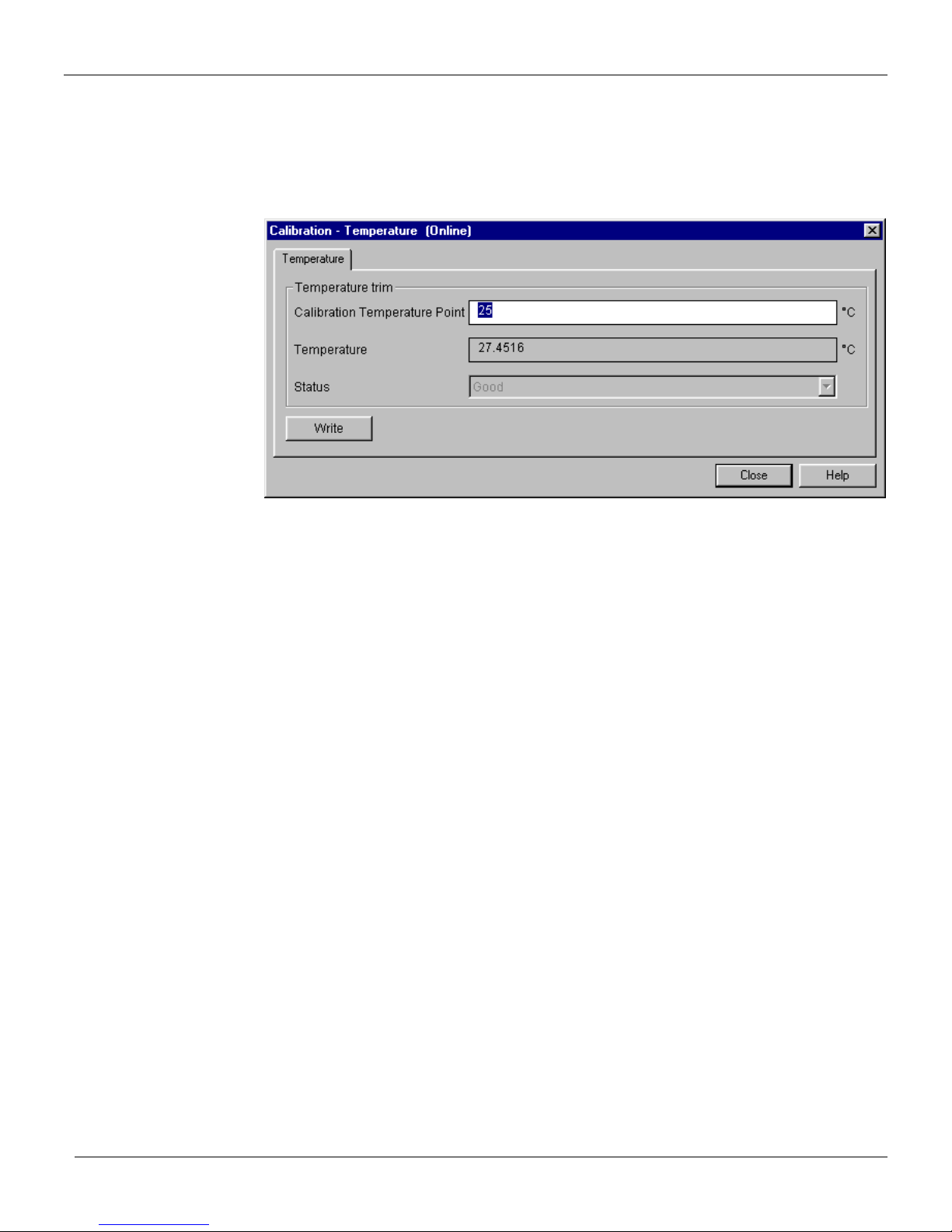
Temperature Compensati on
Using the Calibration Temperature Menu at the Device, the user can trim the temperature sensor
located at the body of positioner in order to improve the accuracy of temperature measurement
done by its sensor. The range accepts from -40°C to +85 °C. The temperature parameter indicates
the value of such measurement.
Configuration
Figure 3.33 - Calibrating the Temperature Sensor
3.35
Page 62
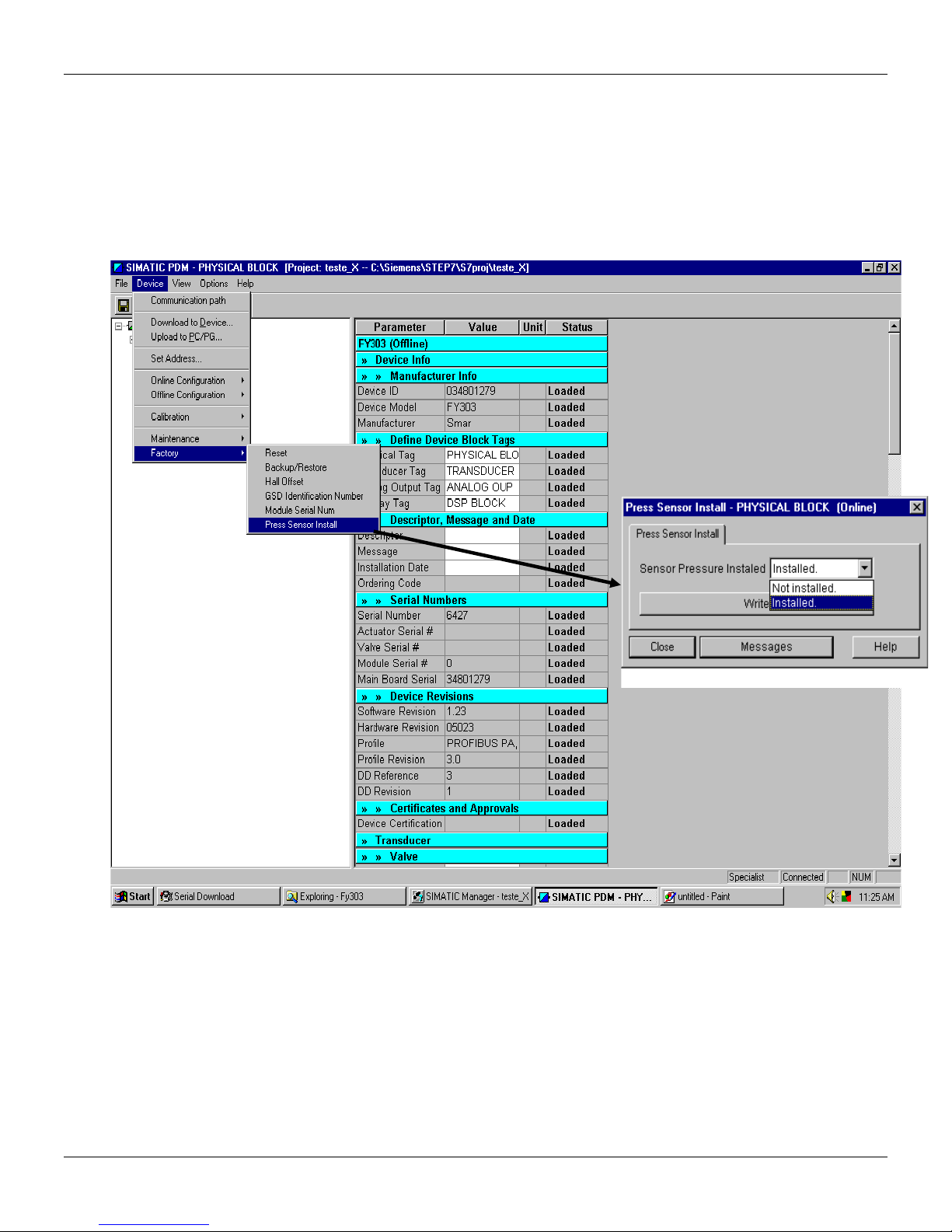
FY303 – Operation, Maintenance and Instructions Manual
Pressure Sensors Version (K1 Option)
The K1 option of the FY303 is available with 3 pressure sensors, namely one for input and two for
both outputs.
How to check the pressure sensors installation
In terms of configuration, after identifying the presence of the sensors on the hardware, their
installation may be checked via Simatic PDM. To this effect, choose “Factory” on the “Device” menu
and select “Press Sensor Install”, as shown below:
Figure 1 – Checking the FY303 Pressure Sensors Installation
Pressure sensor calibration
To check or calibrate the pressure sensor with the Simatic PDM, refer to the “Device” menu and
choose “Calibration” and then “Pressure Sensor Cal”, as shown on figure 2.
3.36
Page 63
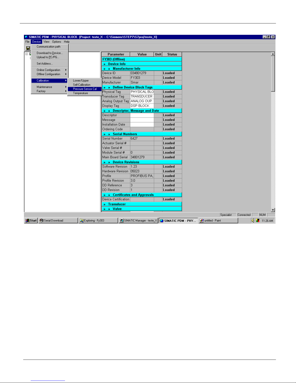
Configuration
Figure 2 – Pressure Sensors Calibration
Next step is selecting which sensor is to be calibrated: if the input (Press In), or the output 1 (Out 1),
or the output 2 (Out 2). See figure 3.
3.37
Page 64
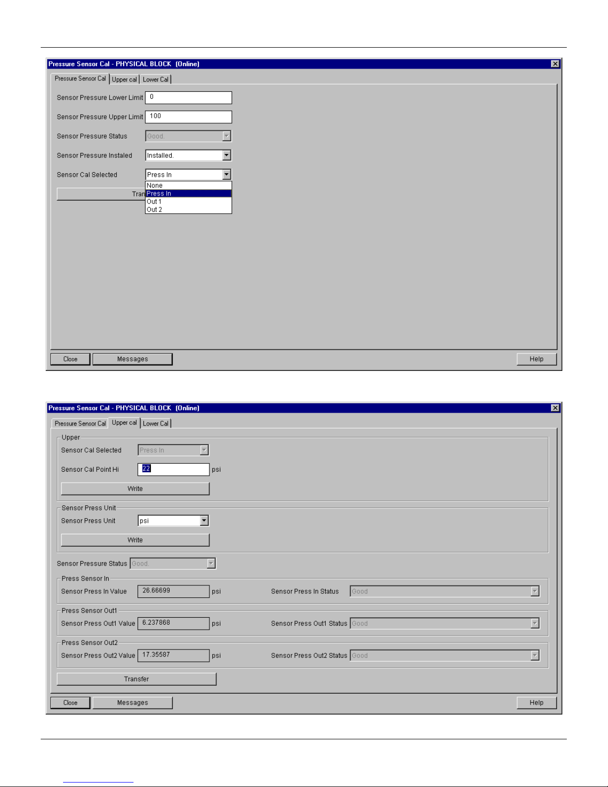
FY303 – Operation, Maintenance and Instructions Manual
Figure 3 – Selecting the Sensors for Pressure Calibration
3.38
Figure 4 – Upper Pressure Point Calibration
Page 65
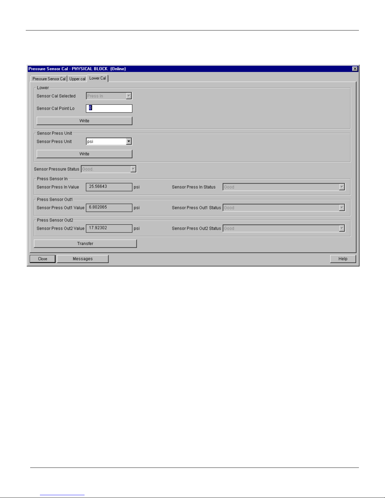
Configuration
After choosing the sensor, click on “Upper” or “Lower” for either point, as shown on figures 4 and 5,
where the user must select the calibration unit and report the reference pressure on Sensor Cal
Point Hi and Sensor Cal Point Lo, watching on the window bottom the values read by the FY303.
Figure 5 – Lower Pressure Point Calibration
FY303 Performance Graph
Go the “View” menu via Simatic PDM and choose one of the options: “Position Performance
Diagram” or “Pressure Diagram”, according to figure 6.
3.39
Page 66
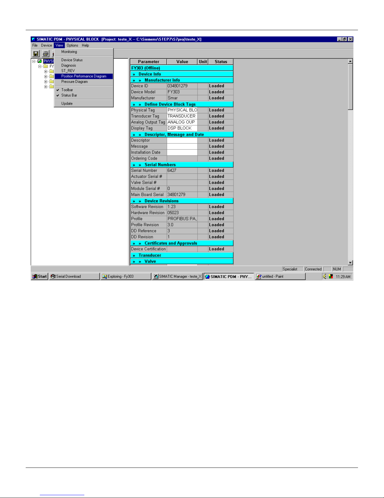
FY303 – Operation, Maintenance and Instructions Manual
Figure 6 – FY303 Graph Selection
When choosing “Position Performance Diagram”, the PDM will show the respective graph, as on
figure 7, where the user may watch the behavior of the real valve position on the SetPoint
throughout the action.
3.40
Page 67
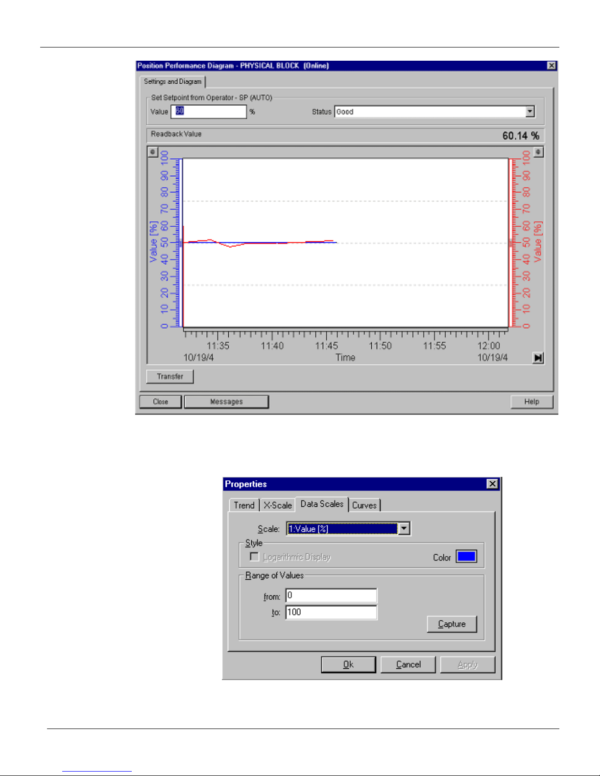
Configuration
Figure 7 – Real Position x SP
Clicking on the scales, the user may adjust them at his discretion and, in addition, zoom in the curve
to locate a specific area.
Figure 8 – Scale adjustment
3.41
Page 68
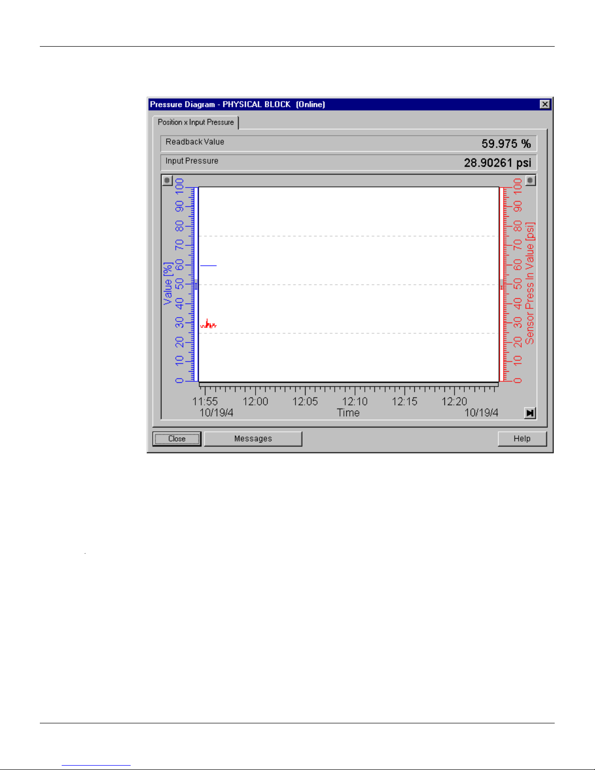
FY303 – Operation, Maintenance and Instructions Manual
By choosing “Pressure Diagram”, the real position may be drawn by the sensor selected on figure 3,
as shown on figure 9. If no sensor was selected, the “Pressure Diagram” option will not be seen on
the “View” menu.
3.42
Figure 9 – Real Position x Pressure
Pressure sensors configuration data on the Transducer block
The pressure sensors are characterized on factory procedure, so, if the configuration data must be
checked, go the “Device” menu, choose “Transducer Offline” and click on the “Pressure Sensors”
tab, as shown on figure 10.
Page 69
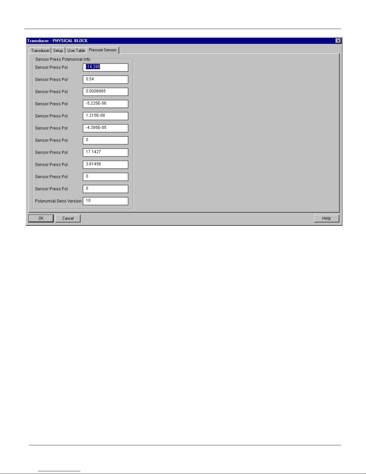
Configuration
Figure 10 – Sensor Pressure Configuration Data
3.43
Page 70

FY303 – Operation, Maintenance and Instructions Manual
3.44
Page 71

Section 4
General
SHOWN ON DISPLAY
COMMUNICATION
NO RESPONSE
TO INPUT SIGNAL
OSCILLATING
SLOW ACTUATOR
TOO FAST ACTUATOR
MAINTENANCE PROCEDURES
FY303 Profibus to Valve Positioners are extensiv ely teste d and inspect ed before d elivery to the end
user. Nevertheless, during their design and development, considerati on was given to the possibility
of repairs by the end user, if necessary.
In general, it is recommended that the end user do not try to repair printed circuit boards. Instead,
he should have spare circuit boards, which may be ordered from Smar whenever necessary.
DIAGNOSTICS
SYMPTOM PROBABLE ERROR SOURCE
Positioner Connections
Check wiring polarity and continuity.
POSITION
NO
ACTUATOR
RESPONSE
RESPONSE
Power Supply
Check the minimum voltage signal equal 9 Volts.
Electronics Failure
Check circuit boards for bad connections and replace them for spare boards.
Network Connection
Check network connections: equipment, power supply, couplers, links, and terminators.
Network Impedance
Check network impedance (power supply and terminators impedance).
Positioner Configuration
Check the configuration of the positioner communication parameters.
Network Configuration
Check the network communication configuration.
Electronics Failure
Try spare parts in the positioner circuits.
Pressure Output Connections
Check up on air leaks.
Air Supply Pressure
Check the air supply pressure. The input pressure to FY303 shall be between 20 psi and
100 psi.
Calibration
Check the positioner calibration points.
Obstructed Restriction and/or Blocked Output
Observe the following procedures described in this Manual: OUTPUT CONNECTIONS
and RESTRICTION CLEANING.
Calibration
Adjust parameter Kp.
Adjust parameter Tr.
Adjustment Parameters are Too Low
Adjust parameter Kp.
Adjustment Parameters are Too High
Adjust parameter Kp.
Table 4.1 - FY303 Diagnostics
If the problem is not presented in the table above follow the Note below:
4.1
Page 72
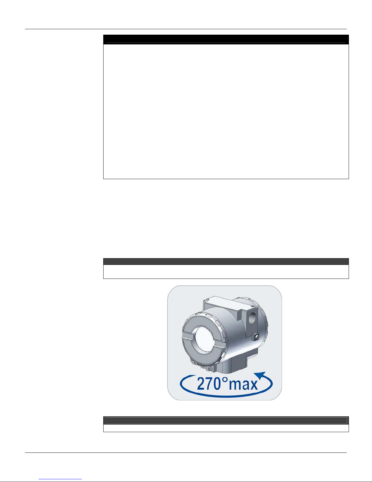
FY303 – Operation, Maintenance and Instructions Manual
The Factory Init should be tried as a last option to recover the equipment control when the equipment presents
some problem related to the function blocks or the communication. This operation must only be carried out
by authorized technical personnel and with the process offline, since the equipment will be configured
with standard and factory data.
This procedure resets all the configurations run on the equipment, after which a partial download should be
performed. With exception to the equipment physical address and the GSD identifier number selector
parameter. After doing this, all configurations must be remade according to their applications.
Two magnetic tools should be used to this effect. On the equipment, withdraw the nut that fixes the
identification tag on the top of the housing, so that access is gained to the "S" and "Z" holes.
The operations to follow are:
1) Switch off the equipment, insert the magnetic tools and keep them in the holes (the magnetic end in the
holes);
2) Feed the equipment;
3) As soon as Factory Init is shown on the display, take off the tools and wait for the "5" symbol on the right
upper corner of the display to unlit, thus indicating the end of the operation.
This procedure makes effective the entire factory configuration and will eliminate eventual problems with the
function blocks or with the equipment communication.
Note that this procedure must be performed by authorized personal only and with the process switched off,
since the equipment will be configured with standard and factory data.
Disassembly Procedure
Make sure to disconnect power supply and supply pressure before disassembling the positioner.
TRANSDUCER
To remove the transducer from the electronic housing, the electrical connections (in the field
terminal side) and the main board connector must be disconnected.
Loosen the hex screw (6) and carefully unscrew the electronic housing from the transducer,
observing that the flat cable is not excessively twisted.
Do not rotate the electronic housing more than 270° without disconnecting the electronic circuit from the power
supply.
NOTE
WARNING
The numbers indicated between parentheses refer to Figure 5.4 – Exploded View.
4.2
Figure 4.1 - Transducer Rotation
NOTE
Page 73
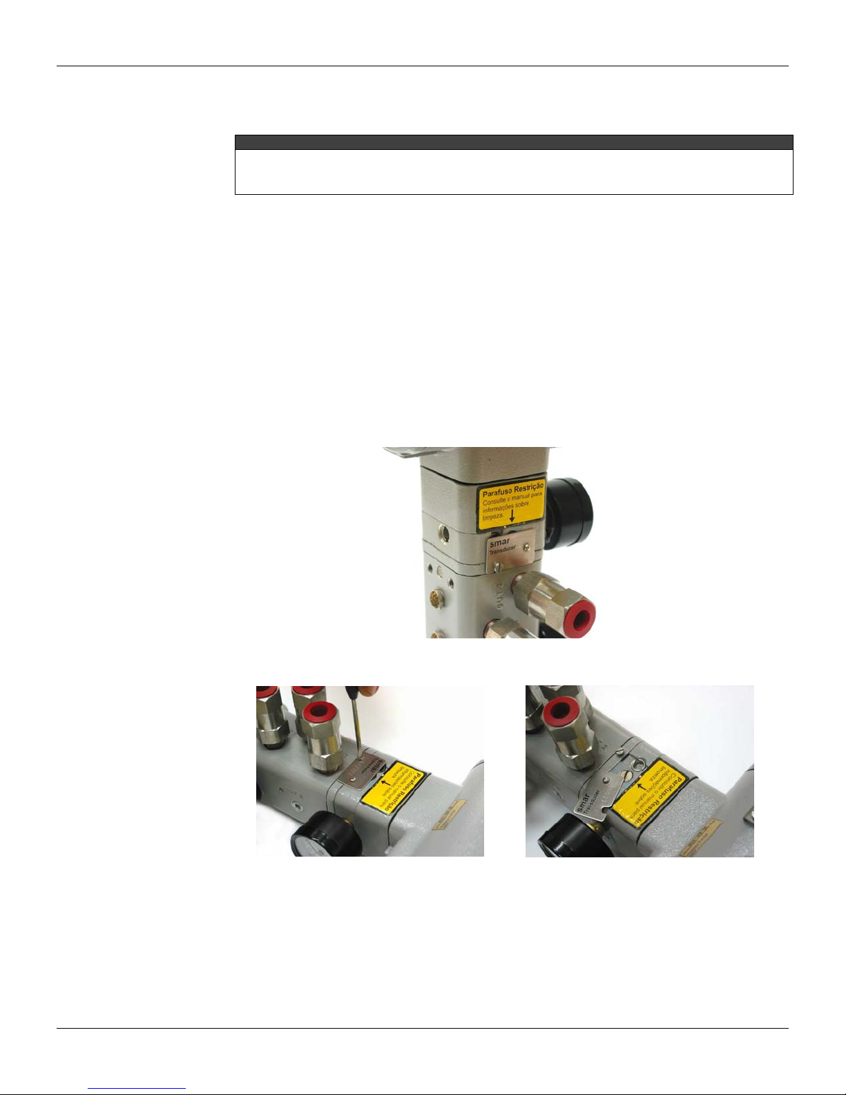
ELECTRONIC CIRCUIT
To remove the circuit board (5) and indicator (4), first loose the cover locking (13) on the side not
marked “Field Terminals”, then unscrew the cover (1).
The boards have CMOS components, which may be damaged by electrostatic discharges. Observe correct
procedures for handling CMOS components. It is also recommended to store the circuit boards in anti-static
proof cases.
Loosen the two screws (3) that anchor the indicator and the main circuit boar d. Gently pull out the
indicator, and then the main board (5).
Reassembly Procedure
TRANSDUCER
Mount the transducer to the housing turning clockwise until it stops. Then turn it count erclockwise
until it faces the square of electronic housing to the square of transducer. Tighten the hex scre w (6)
to lock the housing to the transducer.
Restriction Cleaning Procedure
The air flows to the nozzle through a restriction. Verify from time to time the restriction cleaning to
assure a positioner good performance.
1. Be sure that the air supply of the equipment is blocke d.
Maintenance Procedures
WARNING
2. With an appropriate tool, remove the transdu cer serial n um ber plate. (New models have the
plate placed on the opposite side of the transducer).
3. Remove the restriction screw using an adequate tool;
4.3
Page 74
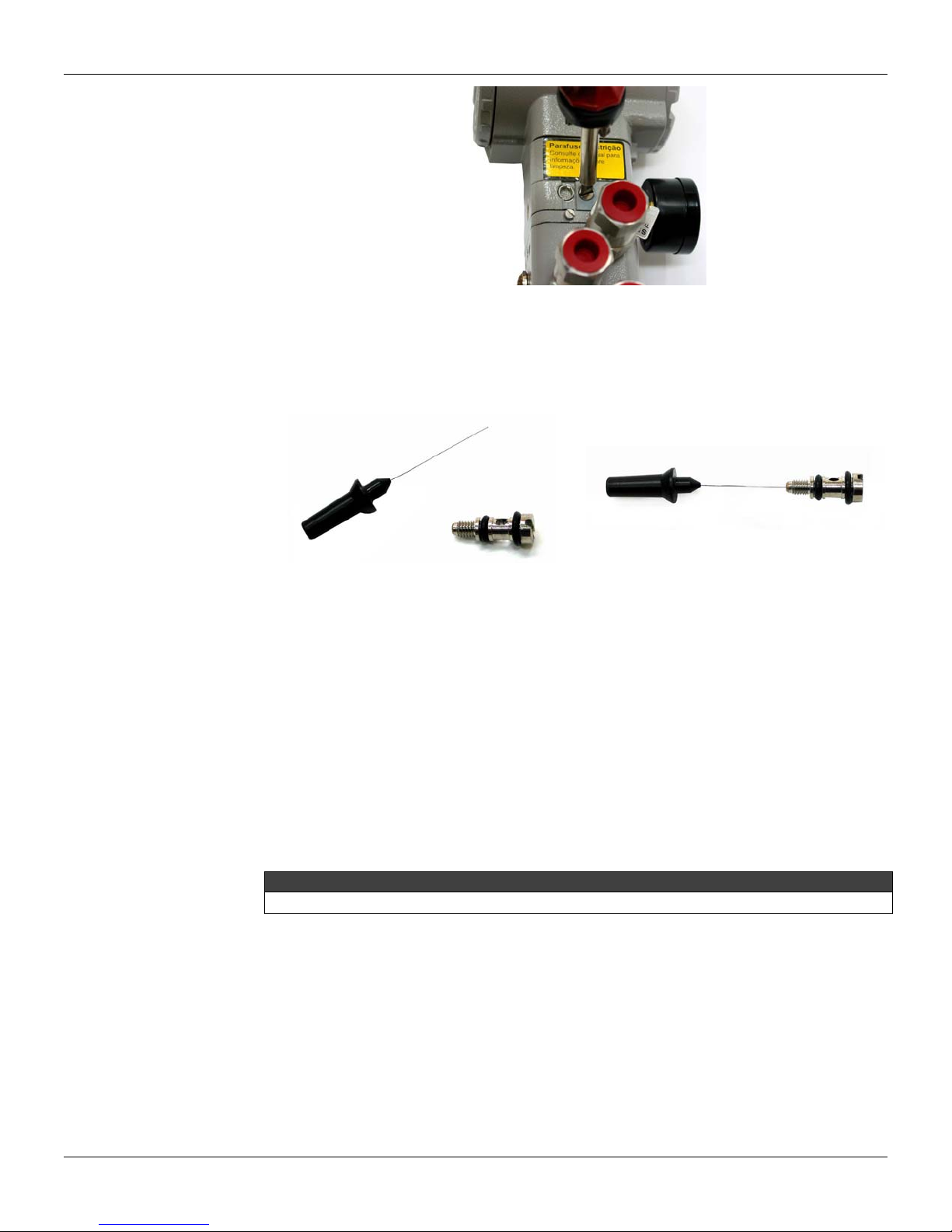
FY303 – Operation, Maintenance and Instructions Manual
4. Remove the o-ring’s with an appropriate tool;
5. Dive the part in petroleum base solvent and dry it with compressed air (apply the
compressed air directly in the smaller orifice for the air to get out through the bigger orifice) .
6. Introduce the appropriate tool (PN 400-0726) into the restriction orifice to prevent any
possible obstruction;
7. Mount the o-rings again and screw the restriction in the positioner.
8. The equipment can be supplied with air again.
Change of the Filter Elements
Change the positioner filter elements with a minimum stated period of 1 (one) year.
The instrumentation air supply must be clean, dry and non-corrosive, following standards indicated
for the American National Standard “Quality Standard for Instrument Air" ANSI / ISA S7.0.01 - 1996.
If the instrumentation air does not comply with the above mentioned standards, the user has to
consider changing the positioner filter elements more frequently.
EXHAUST PORT
Air is vented to the atmosphere through the two exhausts ports located behind the transducer
nameplate. A foreign object interfering or blocked exhaust port provides a way to increase the
output. Cleaning by spraying it with a solvent.
Never use oil or grease in the spool; otherwise the positioner performance will be impaired.
Electronic Circuit
Plug transducer connector and power supply connector to main board (5). Attach the display to the
main board. Observe the four possible mounting positions (Figure 4.2). The mark indicates up
position.
NOTE
4.4
Page 75
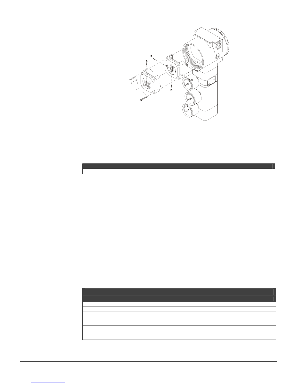
Maintenance Procedures
Interchangeability
Package Content
Figure 4.2 - Four Possible Positions of the Local Indicator
Anchor the main board and indicator with their screws (3). After tightening the protective cover (1),
mounting procedure is complete. The positioner is ready to be energized and tested.
Electrical Connections
The plug must obligatorily be installed in th e electric connection not used, preventing the humidity
entrance.
WARNING
The standard plug provided with Smar positioner do not have an EExd certification.
Main board can be changed and operate with the transducer. There is an EEPROM in the
transducer part that keeps the trim.
When receiving the equipment, verify the package content. The number for items marked with (*)
must be in accordance with the number of positioners.
• Positioner
• Adequate Mounting Brackets
- For the positioner
- For the magnet
• Magnetic Tool for Local Adjustment (*)
• Centralizer Transmitter Device (*)
• Cleaning Device for the Restriction (*)
• Operation, Maintenance and Instructions Manual (*)
ACCESSORIES
ORDERING CODE DESCRIPTION
SD1 Magnetic Tool for Local Adjustment
BC1 Fieldbus/RS232 Interface
PS302 Power Supply
FDI302 Field Device Interface
BT302 Terminator
SB302 Intrinsic
DF48 Fieldbus Repeater
400-0726 Needle cleaning Device for the restriction
4.5
Page 76
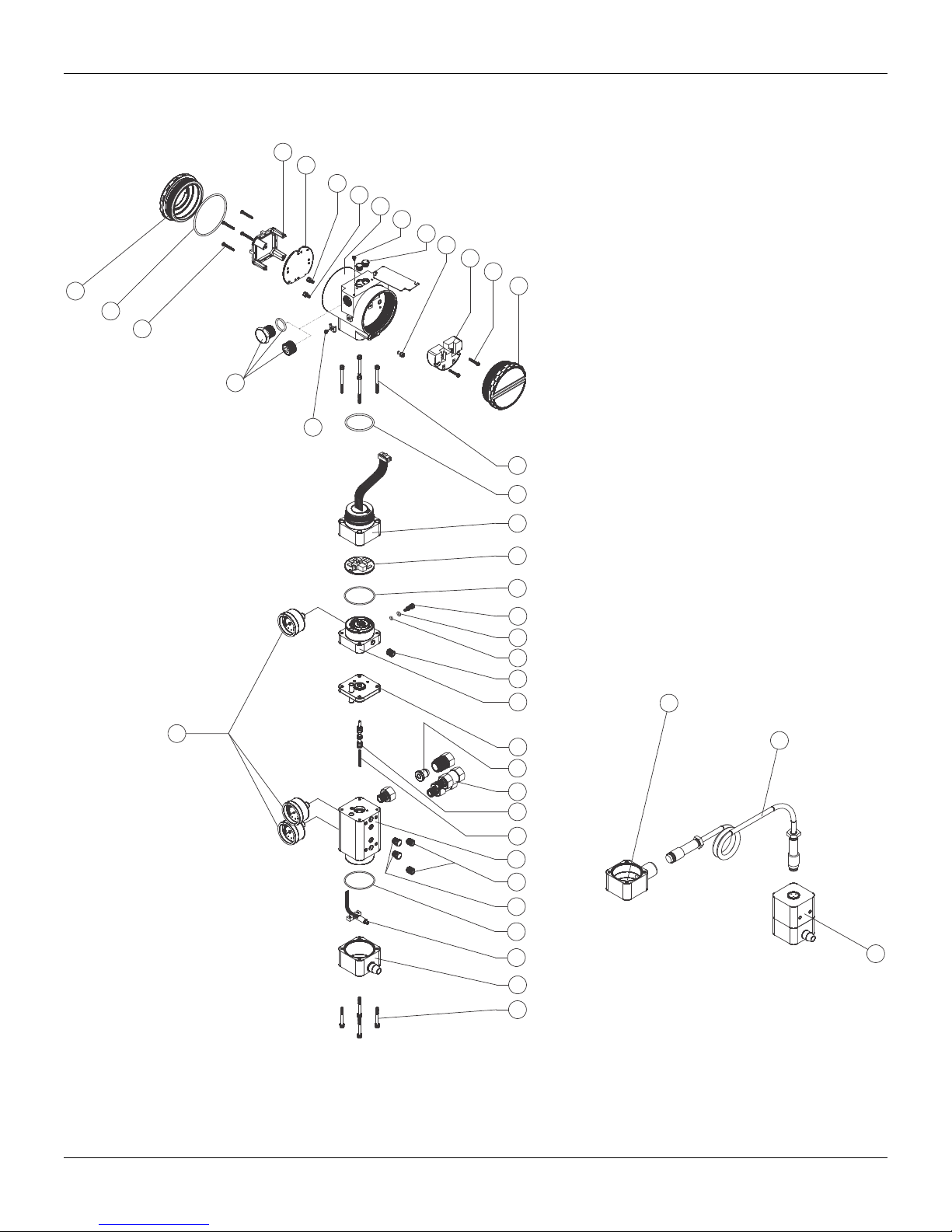
H[525"⁄"Qrgtcvkqp."Ockpvgpcpeg"cpf"Kpuvtwevkqpu"Ocpwcn"
Gzrnqfgf"Xkgy"
4
5
6
7
8
9
10
1
2
3
39
14
6
11
12
13
15
16
17
18
19
20
21
22
23
24
25
27
28
30
29
40
31
23
32
19
35
36
37
38
608"
33
34
Hkiwtg"605"/"Gzrnqfgf"Xkgy"
Page 77

"
Urctg"Rctvu"Nkuv"
PARTS DESCRIPTION POSITION CÓDE
HOUSING (NOTE 1)
COVER (INCLUDES O-RING)
Cover Locking Bolt
Sensor Locking Bolt (M6 Without Head Screw)
External Ground Bolt
Identification Plate Fixing Bolt
Orings Cover (NOTE 2)
Local Adjustment Protection Cover
DIGITAL INDICATOR GLL1438 (for old electronic main board GLL1034)
DIGITAL INDICATOR (for new main boards GLL1461)
TERMINAL INSULATOR
MAIN ELECTRONIC CIRCUIT BOARD (include digital indicator and
mounting kit)
TERMINAL HOLDING BOLT HOUSING
MOUNTING KIT FOR MAIN ELECTRONIC BOARD (new board GLL1461),
(2 bolts with spacers and retention washers)
CONNECTION COVER
. Connection Cover Bolt
. Buna-N Neck O-ring (NOTE 2)
ANALOG BOARD without Pressure Sensor GLL1012 (version K0)
ANALOG BOARD for Pressure Sensor GLL1204 (version K1)
PIEZO BASE SET
. Base and Block O-ring (NOTE 2)
. Restriction
. Restriction External O-ring (NOTE 2)
. Restriction Internal O-ring (NOTE 2)
. Syntherized Bushing
. Analog indicator (Gage - Stainless Steel and Brass) (NOTE 5)
ASSEMBLED DIAPHRAGM (include hall tube, mechanical part and
O-rings)
PNEUMATIC BLOCK SET
. Base & Block O-ring (NOTE 2)
. Syntherized Bushing
. Analog indicator (Gage - Stainless Steel and Brass) (NOTE 5)
. Filtering Element
. Spool valve
. Spool valve Spring
. Stainless steel Filter- 1/4" NPT - includes filtering element
. Vent Plug - Stainless Steel
HALL COVER SET
. Hall Cover Bolt
. Hall Support + Hall Sensor + Flat cable
REMOTE EXTENSION SET
CABLE SET + CONNECTOR
SPARE PARTS LIST
8
1 and 13
6
7
14
9
2
10
4
11 400-0058 A
5 400-1346 A
12
3
15,16 and 17
15
16
18
18
19,20,21,22, 23,24 and 25
19
20
21
22
23
25
27 400-1321 (NOTE 6) B
19,23,25,28,29,30,31 and
32
19
23
25
28
29
40
30
32
33 (or 36), 34 and 35
34
35
38
37
Ockpvgpcpeg"Rtqegfwtgu"
400-1314-3P (NOTE 6)
400-1307 (NOTE 6)
204-0120
400-1121
204-0124
204-0116
204-0122
204-0114
400-1305
400-1310
204-0119
400-0560
400-1320 (NOTE 6)
400-0073
204-0113
400-0060
400-0840
400-1318 (NOTE 6)
400-0085
344-0165
344-0155
344-0150
400-0033
400-1120
400-1317 (NOTE 6)
400-0085
400-0033
400-1120
400-0655
400-0653
400-0787
101B3403
400-0654
400-1319 (NOTE 6)
400-0092
400-0090
400-1322 (NOTE 6)
400-1325 (NOTE 6)
CATEGORY
(NOTE 4)
-
-
-
-
-
-
B
-
A
B
B
A
-
B
-
-
A
B
B
B
B
B
B
A
-
-
-
-
A
-
-
-
-
-
-
-
-
609"
Page 78

H[525"⁄"Qrgtcvkqp."Ockpvgpcpeg"cpf"Kpuvtwevkqpu"Ocpwcn"
SPARE PARTS LIST
PARTS DESCRIPTION POSITION CÓDE
1/2" NPT (Ex d) INTERNAL SOCKET SET PLUG IN BICHROMATIZED
CARBON STEEL
1/2" NPT (Ex d) INTERNAL SOCKET SET PLUG IN 304 SST
1/2" NPT INTERNAL SOCKET SET PLUG IN BICHROMATIZED CARBON
STEEL
1/2" NPT INTERNAL SOCKET SET PLUG IN 304 SST
M20 X 1.5 (Ex d) EXTERNAL SOCKET SET PLUG IN 316 SST
PG13.5 (Ex d) EXTERNAL SOCKET SET PLUG IN 316 SST
3/4" NPT (Ex d) ADAPTER IN 316 SST
TRANSDUCER SET NOTE 3
MAGNETS
. Linear magnet 30mm
. Linear magnet 50mm
. Linear magnet 100mm
. Rotary magnet
MOUNTING BRACKET SCREW FOR POSITIONER ASSEMBLY
(packaged with 12 units)
39
39
39
39
39
39
39
400-1316 (NOTE 6)
-
-
-
-
- 400-1190 -
Vcdng"604"/"Urctg"Rctvu"Nkuv"
1) Includes terminal isolator, bolts (cover locking, ground and terminal isolator) and identification plate without certification.
2)"O-rings are packaged with 12 units."
3)"Includes all transducer’s spare parts."
4) For category A it is recommended to keep in stock 25 parts installed for each set and 50 for category B.
5) The pressure gauges for supply pressure, output 1 or output 2, will be supplied with the wet parts in brass.
6)"For code detailed, use the tables below.
Note:
400-0808
400-0809
400-0583-11
400-0583-12
400-0810
400-0811
400-0812
400-0748
400-0035
400-0036
400-0037
CATEGORY
(NOTE 4)
-
-
-
-
-
-
-
A
-
-
-
-
60:"
Page 79
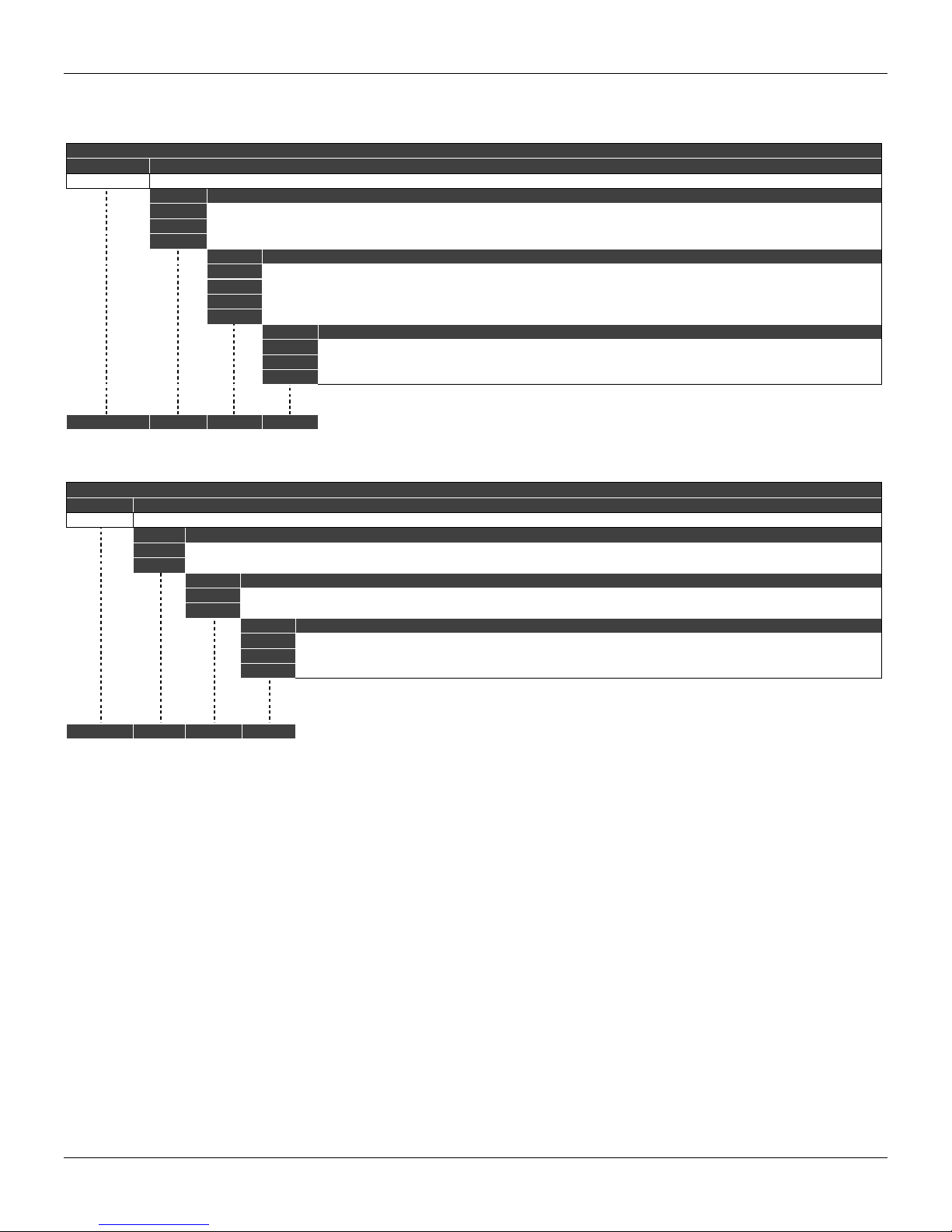
Fgvckngf"Eqfg"Yjgp"Qtfgtkpi"qh"Urctg"Rctvu"
CÓDE DESCRIPTION
400-1314-3P HOUSING; FY303
Option Electrical Connection
0 ½ NPT
A M20 X 1,5
B PG13,5
Option Material
H0 Aluminum (IP/Type)
H1 Stainless Steel (IP/Type)
H2 Aluminum - for saline atmospheres (IPW/Type X)
H4 Aluminum Copper Free (IPW/Type X)
Option Painting
P0 Gray Munsell N 6,5
P8 Without Painting
P9 Safety Blue Epoxy - Electrostatic Painting
400-1314-3F * * * TYPICAL ORDERING CODE
* Choose the desired option
CÓDE DESCRIPTION
400-1307 Cover
Option Type
0 Without window for display
1 With window for display
Option Material
H0 Aluminum (IP/TYPE)
H1 Stainless Steel (IP/TYPE)
Option Painting
P0 Gray Munsell N 6,5
P8 Without Painting
P9 Safety Blue Epoxy - Electrostatic Painting
400-1307 * * * TYPICAL ORDERING CODE
* Choose the desired option.
DETAILED CODE WHEN ORDERING OF SPARE PARTS
DETAILED CODE WHEN ORDERING OF SPARE PARTS
Ockpvgpcpeg"Rtqegfwtgu"
60;"
Page 80
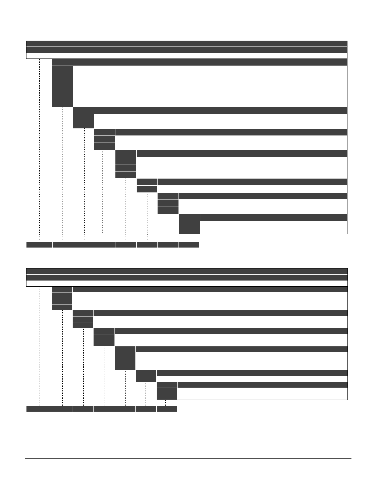
H[525"⁄"Qrgtcvkqp."Ockpvgpcpeg"cpf"Kpuvtwevkqpu"Ocpwcn"
CÓDE DESCRIPTION
400-1316 Transducer Set; FY30X
Option Indication Gage
0 Without Gage
6 01 Gage - Input
7 01 Gage – Output 1
8 02 Gage – Input and Output 1
9 02 Gage – Output 1 and 2
A 03 Gage
Option Action of Positioner
C Single Action
D Double Action
Option Material
H0 Aluminum (IP/TYPE)
H1 Stainless Steel (IP/TYPE)
Option Painting
P0 Gray Munsell N 6,5
P8 Without Painting
P9 Safety Blue Epoxy - Electrostatic Painting
Option Standard of Manufacture
S0 Smar
Option Hall Remote Sensor
R0 Standard Mounting (Without Hall Remote Sensor)
R9 Remote Mounting (adapted for Remote Sensor)
Option Special Sensor
K1 With Pressure Sensors for Diagnostic
400-1316 * * * * * * * TYPICAL ORDERING CODE
* Choose the desired option.
CÓDE DESCRIPTION
400-1317 Pneumatic Block Set; FY30X
Option Indication Gage
0 Without Gage
7 01 Gage – Output 1
9 02 Gage – Output 1 and 2
Option Action of Positioner
C Single Action
D Double Action
Option Material
H0 Aluminum (IP/TYPE)
H1 Stainless Steel (IP/TYPE)
Option Painting
P0 Gray Munsell N 6,5
P8 Without Painting
P9 Safety Blue Epoxy - Electrostatic Painting
Option Standard of Manufacture
S0 Smar
Option Special Sensor
K0 Without Special Sensor
K1 With Pressure Sensor for Diagnostic
400-1317 * * * * * TYPICAL ORDERING CODE
* Choose the desired option.
DETAILED CODE WHEN ORDERING OF SPARE PARTS
Without Special Sensor
K0
DETAILED CODE WHEN ORDERING OF SPARE PARTS
6032"
Page 81
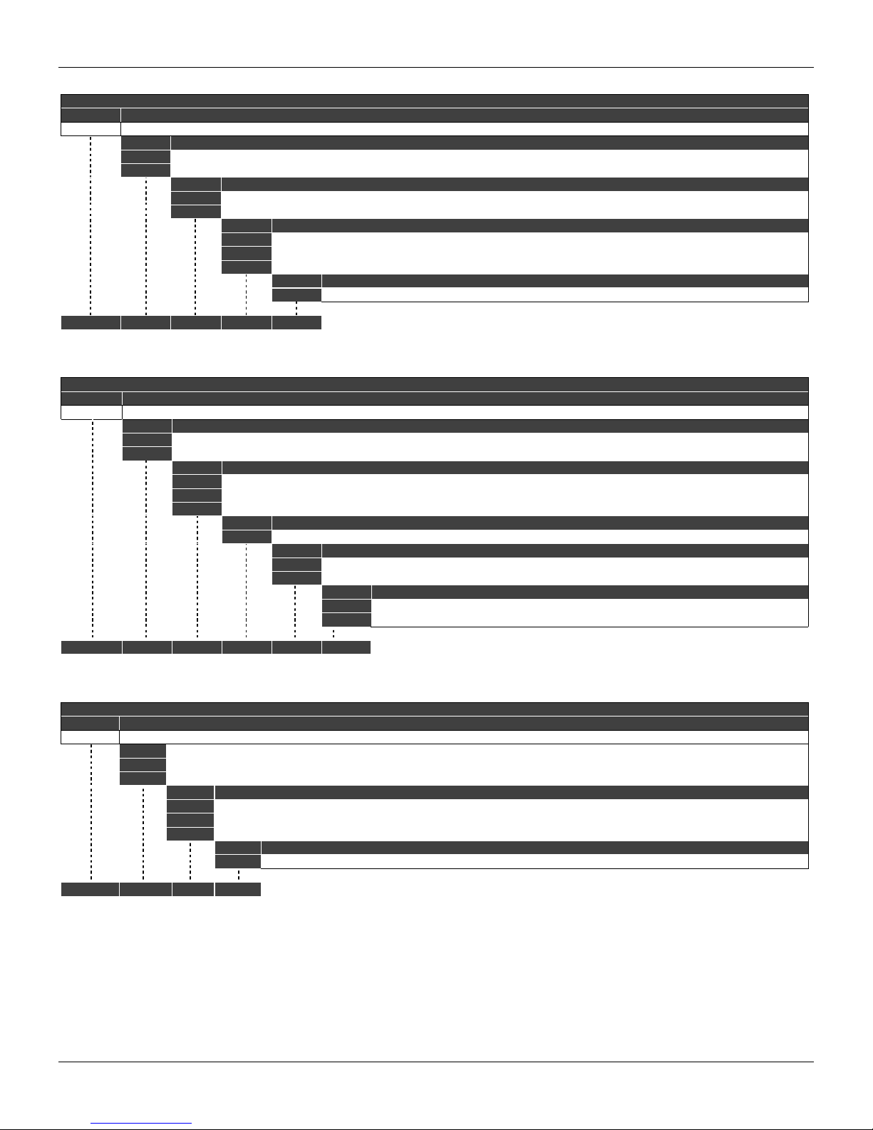
CÓDE DESCRIPTION
400-1318 Piezo Base Set; FY30X
Option Indication Gage
0 Without Gage
6 01 Gage – Input
Option Material
H0 Aluminum (IP/TYPE)
H1 Stainless Steel (IP/TYPE)
Option Painting
P0 Gray Munsell N 6,5
P8 Without Painting
P9 Safety Blue Epoxy - Electrostatic Painting
Option Standard of Manufacture
S0 Smar
400-1318 * * * * TYPICAL ORDERING CODE
* Choose the desired option.
CÓDE DESCRIPTION
400-1319 Hall Cover Set; FY30X
Option Material
H0 Aluminum (IP/TYPE)
H1 Stainless Steel (IP/TYPE)
Option Painting
P0 Gray Munsell N 6,5
P8 Without Painting
P9 Safety Blue Epoxy - Electrostatic Painting
Option Standard of Manufacture
S0 Smar
Option Hall Remote Sensor
R0 Standard Mounting (Without Hall Remote Sensor)
R9 Remote Mounting (adapted for Remote Sensor)
Option Special Sensor
KA For Pneumatic Block without Pressure Sensors
KB For Pneumatic Block with Pressure Sensors
400-1319 * * * * * TYPICAL ORDERING CODE
* Choose the desired option.
CÓDE DESCRIPTION
400-1320 Connection Cover; FY30X
Option Material
H0 Aluminum (IP/TYPE)
H1 Stainless Steel (IP/TYPE)
Option Painting
P0 Gray Munsell N 6,5
P8 Without Painting
P9 Safety Blue Epoxy - Electrostatic Painting
Option Standard of Manufacture
S0 Smar
400-1320 * * * TYPICAL ORDERING CODE
* Choose the desired option.
DETAILED CODE WHEN ORDERING OF SPARE PARTS
DETAILED CODE WHEN ORDERING OF SPARE PARTS
DETAILED CODE WHEN ORDERING OF SPARE PARTS
Ockpvgpcpeg"Rtqegfwtgu"
6033"
Page 82
H[525"⁄"Qrgtcvkqp."Ockpvgpcpeg"cpf"Kpuvtwevkqpu"Ocpwcn"
CÓDE DESCRIPTION
400-1321 Assembled Diaphragm; FY30X
Option Material
H0 Aluminum (IP/TYPE)
H1 Stainless Steel (IP/TYPE)
Option Painting
P0 Gray Munsell N 6,5
P8 Without Painting
P9 Safety Blue Epoxy - Electrostatic Painting
Option Standard of Manufacture
S0 Smar
400-1321 * * * TYPICAL ORDERING CODE
* Choose the desired option.
CÓDE DESCRIPTION
400-1322 Remote Extension Set; FY30X
Option Material
H0 Aluminum (IP/TYPE)
H1 Stainless Steel (IP/TYPE)
Option Painting
P0 Gray Munsell N 6,5
P8 Without Painting
P9 Safety Blue Epoxy - Electrostatic Painting
Option Standard of Manufacture
S0 Smar
400-1322 * * * TYPICAL ORDERING CODE
* Choose the desired option.
CÓDE DESCRIPTION
400-1325 Cable Set and Connectors for Hall Remote Sensor; FY30X
Option Cable Length
1 5 m
2 10 m
3 15 m
4 20 m
Z Special
400-1325 * TYPICAL ORDERING CODE
* Choose the desired option.
DETAILED CODE WHEN ORDERING OF SPARE PARTS
DETAILED CODE WHEN ORDERING OF SPARE PARTS
DETAILED CODE WHEN ORDERING OF SPARE PARTS
6034"
Page 83

Section 5
Ω
TECHNICAL CHARACTERISTICS
Functional Specifications
Travel
Linear Motion: 3 - 100 mm.
Rotary Motion: 30 - 120°
Input Signal
Digital only. Fieldbus, 31.25 kbits/s voltage mode with bus power.
Output
Output to actuator 0 -100% supply air pressure. Single or double-action.
Power Supply
Bus powered: 9-32 Vdc.
Output impedance (from 7.8 kHz - 39 kHz):
Non-intrinsic safety: 3 k
Intrinsic safety: 400 (assuming an IS barrier in the power supply). Ω
Pressure Supply
1.4 - 7 bar (20-100 psi) free of oil, dust and water.
Indication
Optional 4 ½ - digit numerical and 5-character alphanumerical LCD ind icator.
Hazardous Location Certification
Explosion proof, weather proof and intrinsically safe CEPEL, FM, CSA, NEMKO and DMT standards
(pending).
Temperature Limits
Operation: -40 to 85ºC (-40 to 185ºF).
Storage: -40 to 90ºC (-40 to 194ºF).
Display: -10 to 75ºC ( 14 to 167ºF) operation.
-40 to 85ºC (-40 to 185ºF) without damage.
Remote Hall
Operation: -40 to 105ºC (-40 to 221ºF).
Humidity Limits
0 to 100% RH.
Turn-on Time
Approximately 10 seconds.
Update Time
Approximately 0.5 second.
Flow Characterization
Linear, equal percentage, quick opening and customer configuration through Fieldbus
communication from e.g., a PC or by the local adjustment switches.
Gain
Through software. Locally adjustable.
Travel Time
Through software. Locally adjustable.
Actual Position Sensing
Magnet (Non-contact) via Hall Effect.
Configuration
Basic configuration may be done using local adj ustment magn etic tool if device is fitted with display.
Complete configuration is possible using remote configurator (Ex.: Simatic PDM, from Siemens).
.
5.1
Page 84

FY303 – Operation, Maintenance and Instructions Manual
Performance Specifications
Resolution
≤ 0.1% F.S.
Repeatability
≤ 0.1% F.S.
Hysteresis
≤ 0.1% F.S.
Consumption
0.35 Nm/h (0.20 SCFM) at 1.4 bar (20 psi) supply.
1.10 Nm/h (1.65 SCFM) at 5.6 bar (80 psi) supply.
Output Capacity
13.6 Nm
Ambient Temperature Effect
0.8% / 20 ºC of span.
Supply Pressure Effect
Negligible.
Vibration Effect
±0.3%/g of span during the following conditions:
5-15 Hz at 4 mm constant displacement.
15-150 Hz at 2g.
150-2000 HZ at 1g.
Reference SAMA PMC 31.1 - 1980, Sec. 5.3, Condition 3, Steady State.
Electro-Magnetic Interference Effect
Designed to comply with IEC 801 and European Standards EN50081 and EN50082.
3
/h (8 SCFM) at 5.6 (80 psi) supply.
Physical Specifications
Hardware
Physical: according to IEC 61158-2 and conformity with the FISCO model.
Electrical Connection
1/2 -14 NPT, Pg 13.5 or M20 x 1.5.
Pneumatic Connections
Supply and output: 1/4 - 18 NPT
Gage: 1/8 - 27 NPT
Material of Construction
Injected low copper aluminum with polyester painting or 316 Stai nless Steel housing, with Buna-N
O-rings on cover (NEMA 4X, IP66).
Weight
Without display and mounting bracket: 2.7 kg. (Aluminum)
5.8 Kg. (Stainless Steel)
Add for digital display: 0.1 kg.
Remote Sensor: 550g.
Cable: 100g. (plus 45g/m for each connector)
5.2
Page 85
Vgejpkecn"Ejctcevgtkuvkeu"
Qtfgtkpi"Eqfg"
MODEL SMART VALVE POSITIONER
FY303 PROFIBUS PA
COD. Local Indicator
COD. Mounting Bracket
COD. Electrical Connections
COD. Type of Actuator
COD. Indication Gage
SPECIAL OPTIONS
COD. Housing
COD. Identification Plate
COD. Painting
COD. TAG Plate
J0 With TAG J1 Blank J2 According to user’s notes
COD. Sensor Mounting (1)
COD. Special Sensor
COD. Special
ZZ Specify (*)
FY303 1 0 0 1 0
* Leave it blank for no optional items.
(1) Consult Smar for applications in classified areas.
(2) IPW/TYPEX tested for 200 hours according to NBR 8094 / ASTM B 117 standard.
(3) Options not certified for hazardous locations.
(4) Certificate for use in Hazardous Locations (CEPEL, NEMKO, NEPSI, EXAM, FM, CSA).
0
Without Indicator
1
With Digital Indicator
0
Without Bracket
1
With Bracket
0
1
2
1/2" - 14 NPT (4)
1/2" - 14 NPT X 3/4 NPT (316 SS) - with adapter (5)
1/2" - 14 NPT X 3/4 BSP (316 SS) - with adapter (3)
1
Rotary - Single Action
2
Rotary - Double Action
3
Linear Stroke Up to 15 mm. - Single Action
4
Linear Stroke Up to 15 mm. - Double Action
5
Linear Stroke Up to 50 mm. - Single Action
6
Linear Stroke Up to 50 mm. - Double Action
7
Linear Stroke Up to 100 mm. - Single Action
Without Gage
0
With 1 Gage (Acrylic, Stainless steel and wetted parts in brass) - Input
6
With 1 Gage (Acrylic, Stainless steel and wetted parts in brass) -
7
Output 1
With 2 Gage (Acrylic, Stainless steel and wetted parts in brass) - Input
8
and Output 1
H0
Aluminum (IP/Type)
H1
316 Stainless Steel (IP/Type)
H2
Aluminum for saline atmosphere (IPW/Type X) (2)
I1
FM: XP, IS, NI, DI
I3
CSA: XP, IS, NI, DI
I4
EXAM (DMT): EX-IA, NEMKO: EX-D
I5
CEPEL: EX-D, EX-IA
I6
Without certification
P0
Gray Munsell N 6.5 Polyester
P8
Without Painting
P9
Blue Safety Epoxy – Electrostatic Painting
PD
Blue smooth diamond RAL5010 - Epoxy
R0
Full Mounting
R1
Remote sensor - 5 m cable
R2
Remote sensor - 10 m cable
R3
Remote sensor - 15 m cable
R4
Remote sensor - 20 m cable
R9
Remote Mounting (adapted for Remote Sensor, without cable and remote extension set)
RZ
Specify (*)
Without special sensor
K0
With pressure sensors for diagnostic
K1
* * * * * * *
NOTES
1/2" - 14 NPT X 1/2 BSP (316 SS) - with adapter (3)
3
M20 X 1.5 (6)
A
B
PG 13.5 DIN (7)
8
Linear Stroke Up to 100 mm. - Double Action
A
Linear Stroke Up to 30 mm. - Single Action
B
Linear Stroke Up to 30 mm. - Double Action
C
Without magnet (for linear actuator ) - Single Action
D
Without magnet (for linear actuator) - Double Action
Z
Others Specify
Whit 2 Gage (Acrylic, Stainless steel and wetted parts in brass)
9
- Output 1 and 2
A
With 3 Gage (Acrylic, Stainless steel and wetted parts in brass)
Others Specify
Z
H3
316 Stainless Steel for saline atmosphere (IPW/Type X) (2)
H4
Copper Free Aluminum (IPW/Type X) (2)
IDIONEPSI: Ex-ia, Ex-d
CEPEL: Ex-tb (explosive dust - Zone 21)
TYPICAL MODEL NUMBER
(5) Certificate for use in Hazardous Locations (CEPEL, FM, CSA).
(6) Certificate for use in Hazardous Locations (CEPEL, NEPSI, NEMKO, EXAM, FM).
(7) Certificate for use in Hazardous Locations (CEPEL, NEPSI, NEMKO, EXAM).
"
705"
Page 86
H[525"⁄"Qrgtcvkqp."Ockpvgpcpeg"cpf"Kpuvtwevkqpu"Ocpwcn"
BFY BRACKET (**)
CODE Positioner Mounting Bracket
CODE Magnet Mounting Bracket
COD. Positioner Mounting Bracket Material
COD. Magnet Bracket Material
COD. Optional Items (*)
ZZ Specify Actuator Model / Manufacturer
Without Bracket
0
1
Universal Rotary
Universal Linear - Yoke and Pillar Type
2
Linear - Yoke Type
3
Linear - Pillar Type
4
Others - Specify
Z
0
1
2
3
4
Z
Without Bracket
Rotary
Linear up to 15 mm / 30 mm.
Linear up to 50 mm.
Linear up to 100 mm.
Others - Specify
7
Carbon Steel Bracket and Accessories in SST
Carbon Steel Bracket
C
Stainless Steel Bracket
I
Not applicable
N
Others - Specify
Z
Carbon Steel Bracket
C
Stainless Steel Bracket
I
Not applicable
N
Others - Specify
Z
BFY - 1 0 7 C . * TYPICAL MODEL NUMBER
* Leave it blank for no optional item.
** For customized mounting bracket, for different brands and models, please, consult www.smar.com .
When choosing the remote sensor version, an additional “L” shape bracket is included, for 2” tube mounting.
706"
Page 87
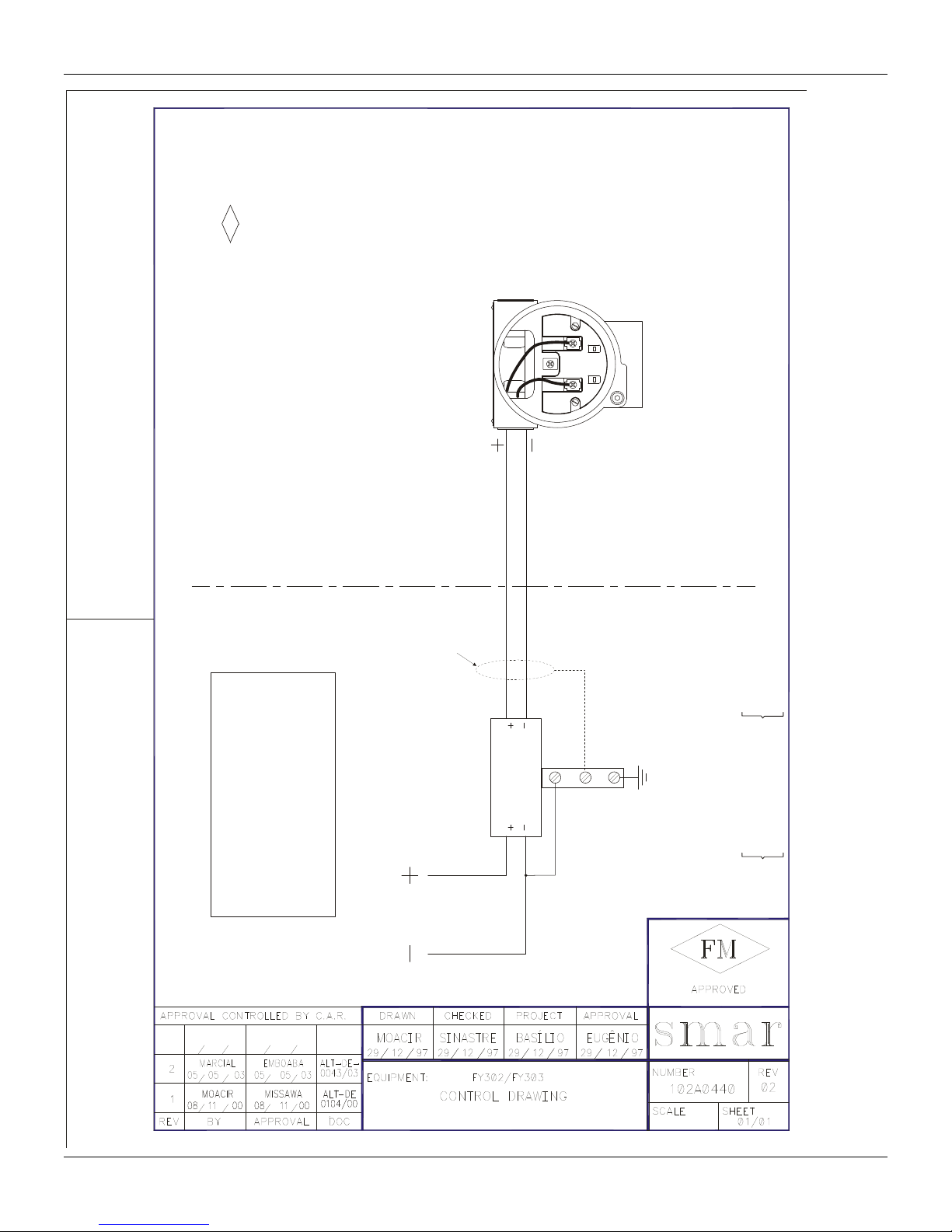
HAZARDOUS AREA
FM
INTRINSICALLY SAFE APPARATUS
ENTITY VALUES: Ci = 5nF Li=12uH
Vmax <= 24V
Technical Characteristics
COMPONENTS CAN NOT
BE SUBSTITUTED WITHOUT
PREVIOUS MANUFACTURER
APPROVAL.
-
Comm.
+-+
Imax <= 250mA
CLASS I,II,III DIV.1, GROUPS A,B,C,D,E,F & G
MODEL FY302 & FY303 - SERIES
POSITIONER
REQUIREMENTS:
1 - INSTALLATION TO BE IN ACCORDANCE WITH ANSI/ISA RP12-6
NON HAZARDOUS OR DIVISION 2 AREA
2 - CONVERTER SPECIFICATION MUST BE IN ACCORDANCE TO
SAFE AREA APP ARA TUS
APPROVAL LISTING.
UNSPECIFIED, EXCEPT THAT IT MUST NOT
3 - ASSOCIATED APPARATUS GROUND BUS TO BE INSULATED FROM PANELS
AND MOUNTING ENCLOSURES.
BE SUPPLIED FROM, NOR CONTAIN UNDER
4 - WIRES: TWISTED PAIR, 22AWG OR LARGER.
5 - SHIELD IS OPTIONAL IF USED, BE SURE TO INSULATE THE END NOT
GROUNDED.
6 - CABLE CAPACITANCE AND INDUTANCE PLUS Ci AND Li MUST BE
SMALLER THAN Ca AND La OF THE ASSOCIATED APPARATUS.
OPTIONAL
SHIELDING
Voc <= 16V
Isc <= 250mA
Po <= 2W
2
La >= CABLE INDUCTANCE + 12uH
FIELDBUS
OPTION
Voc <= 24V
OPTION
Isc <= 250mA
Po <= 1,2W
1
GROUND BUS
BARRIER
FIELDBUS
ASSOCIATED APPARA TUS
ENTITY PARAMETERS FOR ASSOCIATED APPARATUS
CLASS I,II,III DIV.1,
GROUPS A,B,C,D,E,F & G
NORMAL OR ABNORMAL CONDITIONS, A
SOURCE OF POTENTIAL IN RELATION TO
EARTH IN EXCESS OF 250VAC OR 250VDC.
Ca >= CABLE CAPACITANCE + 5nF
POWER SUPPLY
5.5
Page 88

FY303 – Operation, Maintenance and Instructions Manual
5.6
Page 89

Crrgpfkz"C"
CERTIFICATIONS INFORMATION
Gwtqrgcp"Fktgevkxg"Kphqtocvkqp"
Consult www.smar.com for the EC declarations of conformity for all applicable European directives
and certificates.
ATEX Directive (94/9/EC) – “Electrical equipment and protective system intended for use in
potential explosive atmospheres”
The EC-Type Examination Certificate had been released by Nemko AS (CE0470) and/or DEKRA
EXAM GmbH (CE0158), according to European Standards.
The certification body for Production Quality Assurance Notification (QAN) and IECEx Quality
Assessment Report (QAR) is Nemko AS (CE0470).
Jc|ctfqwu"Nqecvkqpu"Igpgtcn"Kphqtocvkqp"
Ex Standards:
IEC 60079-0 General Requirements
IEC 60079-1 Flameproof Enclosures “d”
IEC 60079-11 Intrinsic Safety “i”
IEC 60079-26 Equipment with equipment protection level (EPL) Ga
IEC 60529 Classification of degrees of protection provided by enclosures (IP Code)
Customer responsibility:
IEC 60079-10 Classification of Hazardous Areas
IEC 60079-14 Electrical installation design, selection and erection
IEC 60079-17 Electrical Installations, Inspections and Maintenance
Warning:
Explosions could result in death or serious injury, besides financial damage.
Installation of this instrument in an explosive environment must be in accordance with the national
standards and according to the local environmental protection method. Before proceeding with the
installation match the certificate parameters according to the environmental classification.
General Notes:
Maintenance and Repair
The instrument modification or replaced parts supplied by any other supplier than authorized
representative of Smar Equipamentos Industriais Ltda is prohibited and will void the Certification.
Marking Label
Once a device labeled with multiple approval types is installed, do not reinstall it using any other
approval types. Scratch off or mark unused approval types on the approval label.
For Ex-i protection application
- Connect the instrument to a proper intrinsically safe barrier.
- Check the intrinsically safe parameters involving the barrier, equipment including the cable and
connections.
- Associated apparatus ground bus shall be insulated from panels and mounting enclosures.
- When using shielded cable, isolate the not grounded cable end.
- Cable capacitance and inductance plus C
Apparatus.
For Ex-d protection application
- Only use Explosion Proof/Flameproof certified Plugs, Adapters and Cable glands.
- In an Explosion-Proof/Flame-Proof installation, do not remove the instrument housing covers when
powered on.
- Electrical Connection
In Explosion-Proof installations the cable entries must be connected through conduit with sealed
unit or closed using metal cable gland or closed using metal blanking plug, all with at least IP66
and Ex-d certification. For enclosure with saline environment protection (W) and ingress protection
(IP) applications, all NPT thread parts must apply a proper water-proof sealant (a non-hardening
silicone group sealant is recommended).
and Li must be smaller than Co and Lo of the Associated
i
C03"
Page 90

H[525"⁄"Qrgtcvkqp."Ockpvgpcpeg"cpf"Kpuvtwevkqpu"Ocpwcn"
For Ex-d and Ex-i protection application
- The transmitter has a double protection. In this case the transmitter shall be fitted with appropriate
certified cable entries Ex-d and the electric circuit supplied by a certified diode safety barrier as
specified for the protection Ex-ia.
Environmental Protection
- Enclosure Types (Type X): Supplementary letter X meaning special condition defined as default by
Smar the following: Saline Environment approved - salt spray exposed for 200 hours at 35ºC. (Ref:
NEMA 250).
- Ingress protection (IP W): Supplementary letter W meaning special condition defined as default by
Smar the following: Saline Environment approved - salt spray exposed for 200 hours at 35ºC. (Ref:
IEC60529).
- Ingress protection (IP x8): Second numeral meaning continuous immersion in water under special
condition defined as default by Smar the following: 1 Bar pressure during 24hours. (Ref: IEC60529).
Jc|ctfqwu"Nqecvkqpu"Crrtqxcnu"
CSA (Canadian Standards Association)
Class 2258 02 – Process Control Equipment – For Hazardous Locations (CSA1078546)
Class I, Division 1, Groups B, C and D
Class II, Division 1, Groups E, F and G
Class III, Division 1
Class I, Division 2, Groups A, B, C and D
Class 2258 03 – Process Control Equipment – Intrinsically Safe and Non-Incendive Systems - For Hazardous Locations
(CSA 1078546)
Ex n Class I, Division 2, Groups A, B, C and D
Model FY302 Valve Positioners; input supply 12-42V dc, 4-20mA; Enclosure Type 4/4X; non-incendive with Fieldbus/FNICO
Entity parameters at terminals “+” and “-“ of :
Vmax = 24 V, Imax = 570mA, Pmax = 9,98 W, Ci = 5 nF, Li = 12 µH,
when connected as per SMAR Installation Drawing 102A0836; T Code T3C @ Max Ambient 40 Deg C; MWP 100 psi.
Class 2258 04 – Process Control Equipment – Intrinsically Safe Entity – For Hazardous Locations (CSA 1078546)
Class I, Division 1, Groups A, B, C and D
Class II, Division 1, Groups E, F and G
Class III, Division 1
FISCO Field Device
Model FY302 Valve Positioners; input supply 12-42V dc, 4-20mA; Enclosure Type 4/4X; intrinsically safe with Fieldbus/FISCO
Entity parameters at terminals “+” and “-”:
Vmax = 24 V, Imax = 250 mA, Pmax = 5.32 W, Ci = 5 nF, Li = 12 uH, when connected as per Smar Installation Drawing
102A0836; T Code T3C @ Max Ambient 40 Deg C; MWP 100 psi.
Note: Only models with stainless steel external fittings are Certified as Type 4X.
Special conditions for safe use:
Temperature Class T3C
Maximum Ambient Temperature: 40ºC (-20 to 40 ºC)
Maximum Working Pressure: 100 psi
FMApprovals (Factory Mutual)
Intrinsic Safety (FM 3D9A2.AX)
IS Class I, Division 1, Groups A, B, C and D
IS Class II, Division 1, Groups E, F and G
IS Class III, Division 1
Explosion Proof (FM 3007267)
XP Class I, Division 1, Groups A, B, C and D
Dust Ignition Proof (FM 3D9A2.AX)
DIP Class II, Division 1, Groups E, F and G
DIP Class III, Division 1
C04"
Page 91

Egtvkhkecvkqpu"Kphqtocvkqp"
Non Incendive (FM 3D9A2.AX and 3015629)
NI Class I, Division 2, Groups A, B, C and D
Environmental Protection (FM 3007267, 3D9A2.AX and 3015629)
Option: Type 4X or Type 4
Special conditions for safe use:
Entity Parameters Fieldbus Power Supply Input (report 3015629):
Vmax = 24 Vdc, Imax = 250 mA, Pi = 1.2 W, Ci = 5 nF, Li = 12 uH
Vmax = 16 Vdc, Imax = 250 mA, Pi = 2 W, Ci = 5 nF, Li = 12 uH
Temperature Class T4
Maximum Ambient Temperature: 60ºC (-20 to 60 ºC)
NEMKO (Norges Elektriske MaterielKontroll)
Explosion Proof (NEMKO 00ATEX305X)
Group II, Category 2 G, Ex d, Group IIC, Temperature Class T6, EPL Gb
Ambient Temperature: -20ºC ≤ Ta ≤ +60ºC
Working Pressure: 20-100 psi
Environmental Protection (NEMKO 00ATEX305X)
Options: IP66W or IP66
Special conditions for safe use:
Repairs of the flameproof joints must be made in compliance with the structural specifications provided by the manufacturer.
Repairs must not be made on the basis of values specified in tables 1 and 2 of EN/IEC 60079-1.
The Essential Health and Safety Requirements are assured by compliance with:
EN 60079-0:2012 General Requirements
EN 60079-1:2007 Flameproof Enclosures “d”
EXAM (BBG Prüf - und Zertifizier GmbH)
Intrinsic Safety (DMT 01 ATEX E 011)
Group II, Category 2 G, Ex d [ia], Group IIC, Temperature Class T6, EPL Gb
FISCO Field Device
Supply circuit for the connection to an intrinsically safe FISCO fieldbus-circuit
Ui = 24Vdc, Ii = 380 mA, Pi = 5.32 W, Ci ≤ 5 nF, Li = neg
Parameters of the supply circuit comply with FISCO model according to Annex G EN 60079-11:2012, replacing EN 60079-27:
2008.
Ambient Temperature: -20ºC ≤ Ta ≤ +60ºC
The Essential Health and Safety Requirements are assured by compliance with:
EN 60079-0:2009 + A11:2013 General Requirements
EN 60079-1:2007 Flameproof Enclosures “d”
EN 60079-11:2012 Intrinsic Safety “i”
CEPEL (Centro de Pesquisa de Energia Elétrica)
Intrinsic Safety (CEPEL 00.0017)
Ex d ia, Group IIC, Temperature Class T4/T5/T6, EPL Gb
FISCO Field Device
Entity Parameters:
Pi = 5.32 W, Ui = 24V, Ii = 380 mA, Ci = 5 nF, Li = Neg
Ambient Temperature:
-20 to 65 ºC for T4
-20 to 50 ºC for T5
-20 to 40 ºC for T6
C05"
Page 92

H[525"⁄"Qrgtcvkqp."Ockpvgpcpeg"cpf"Kpuvtwevkqpu"Ocpwcn"
Protection by enclosure (CEPEL 00.0017)
Ex tb, Group IIIC, Temperature Class T135ºC/T100ºC/T85ºC, EPL Db
Ambient Temperature:
-20 to 65 ºC for T135ºC
-20 to 50 ºC for T100ºC
-20 to 40 ºC for T85ºC
Explosion Proof (CEPEL 98.0008)
Ex d, Group IIC, Temperature Class T6, EPL Gb
Maximum Ambient Temperature: 40ºC (-20 to 40 ºC)
Protection by enclosure (CEPEL 98.0008)
Ex tb, Group IIIC, Temperature Class T85ºC, EPL Db
Maximum Ambient Temperature: 40ºC (-20 to 40 ºC)
Environmental Protection (CEPEL 00.0017 AND CEPEL 98.0008)
Options: IP66W or IP66
The Essential Health and Safety Requirements are assured by compliance with:
ABNT NBR IEC 60079-0:2008 General Requirements
ABNT NBR IEC 60079-1:2009 Flameproof Enclosures “d”
ABNT NBR IEC 60079-11:2009 Intrinsic Safety “i”
IEC 60079-27:2008 Fieldbus intrinsically safe concept (FISCO)
ABNT NBR IEC 60529:2009 Classification of degrees of protection provided by enclosures (IP Code)
ABNT NBR IEC 60079-31:2011 Explosive atmospheres - Part 31: Equipment dust ignition protection by enclosure "t"
C06"
Page 93
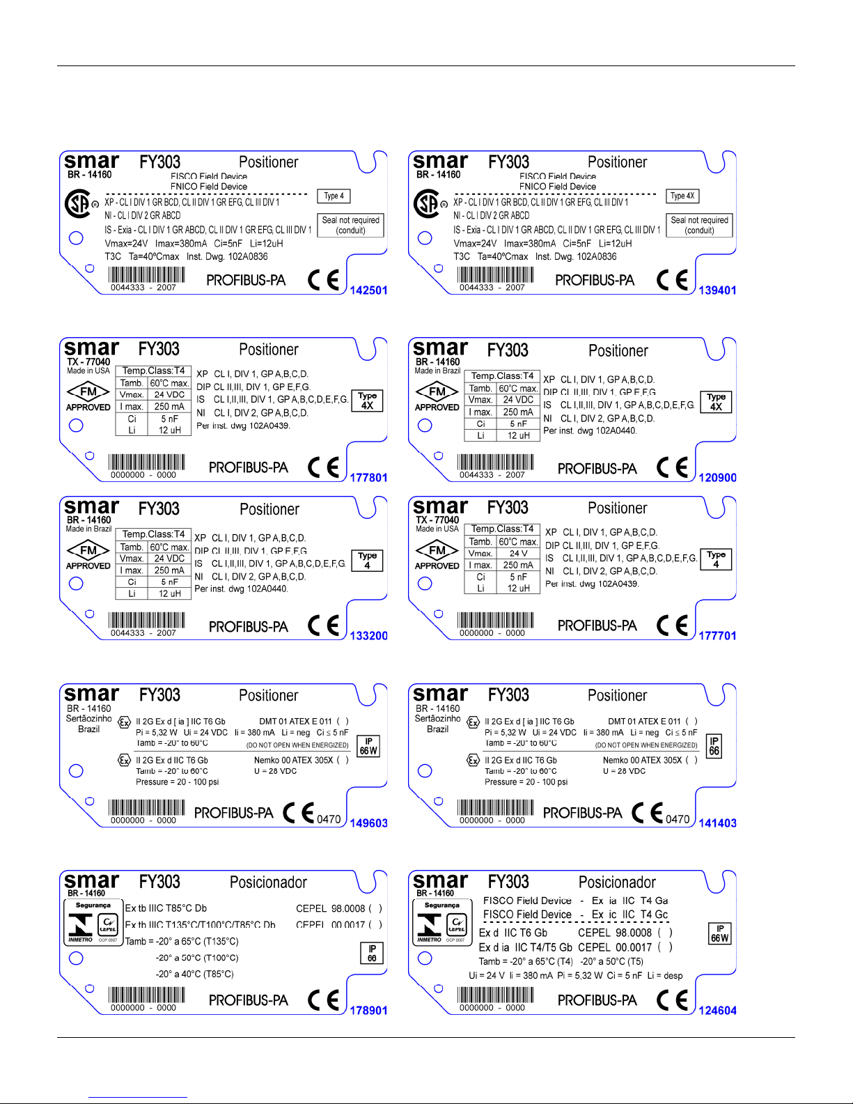
Kfgpvkhkecvkqp"Rncvg""
CSA (Canadian Standards Association)
Egtvkhkecvkqpu"Kphqtocvkqp"
FM Approvals (Factory Mutual)
NEMKO (Norges Elektriske MaterielKontroll) / EXAM (BBG Prüf - und Zertifizier GmbH)
CEPEL (Centro de Pesquisa de Energia Elétrica)
C07"
Page 94
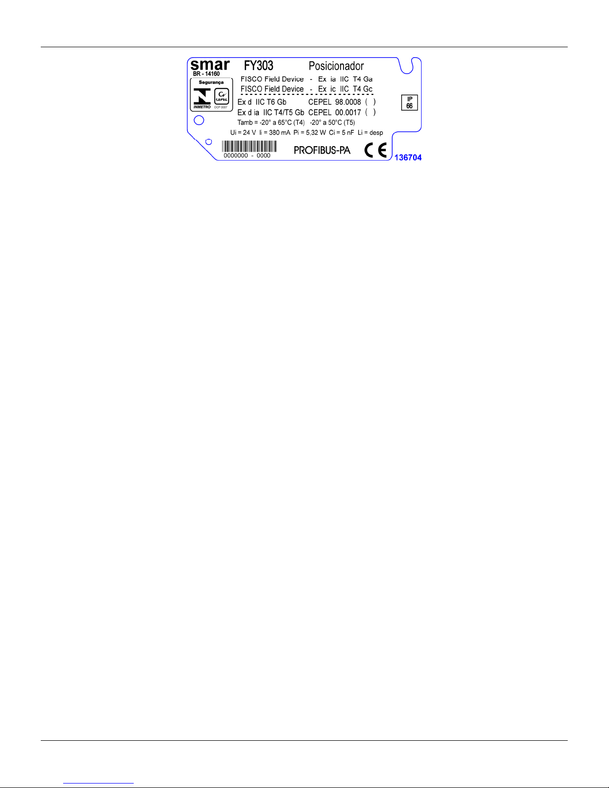
H[525"⁄"Qrgtcvkqp."Ockpvgpcpeg"cpf"Kpuvtwevkqpu"Ocpwcn"
C08"
Page 95
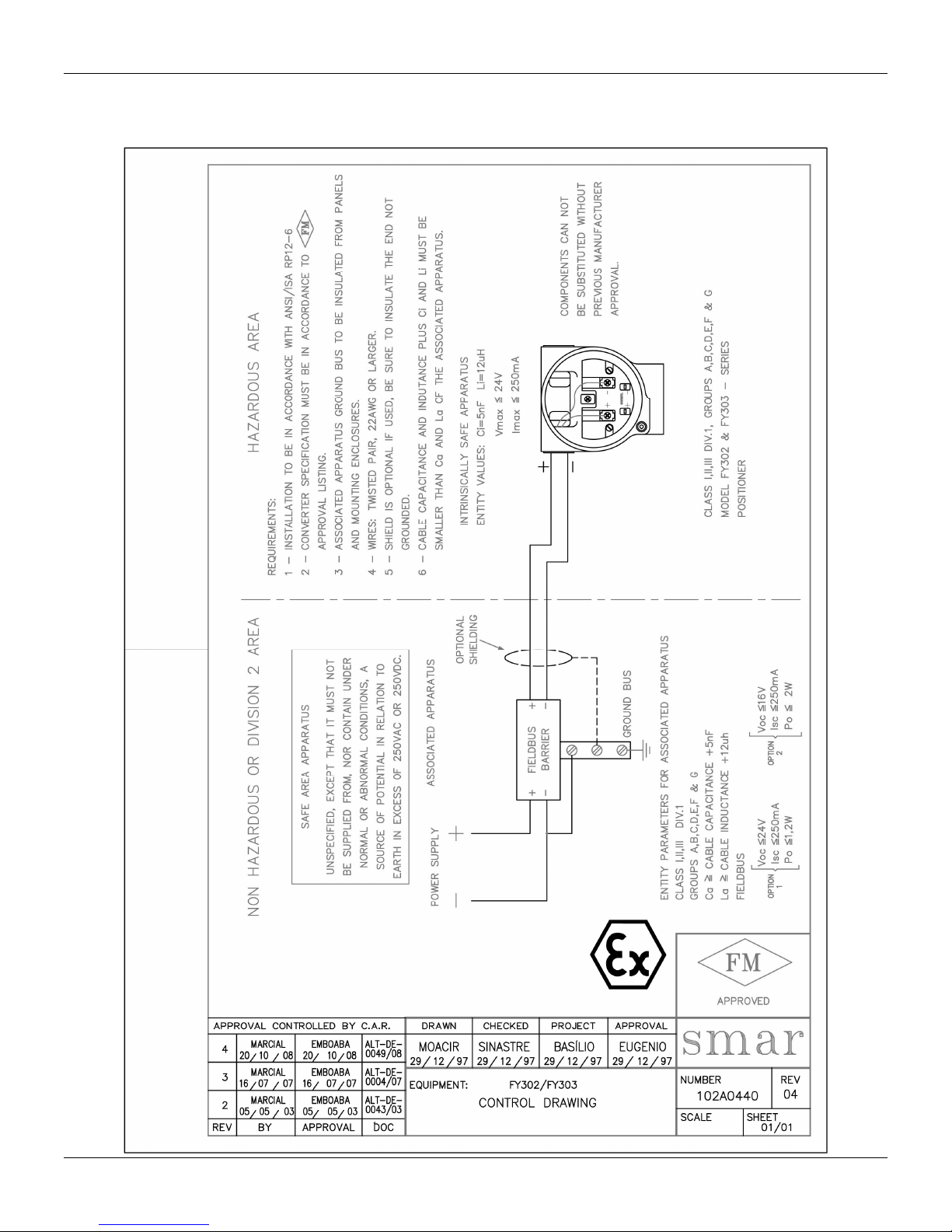
Eqpvtqn"Ftcykpi"
FM Approvals (Factory Mutual)
Egtvkhkecvkqpu"Kphqtocvkqp"
C09"
Page 96
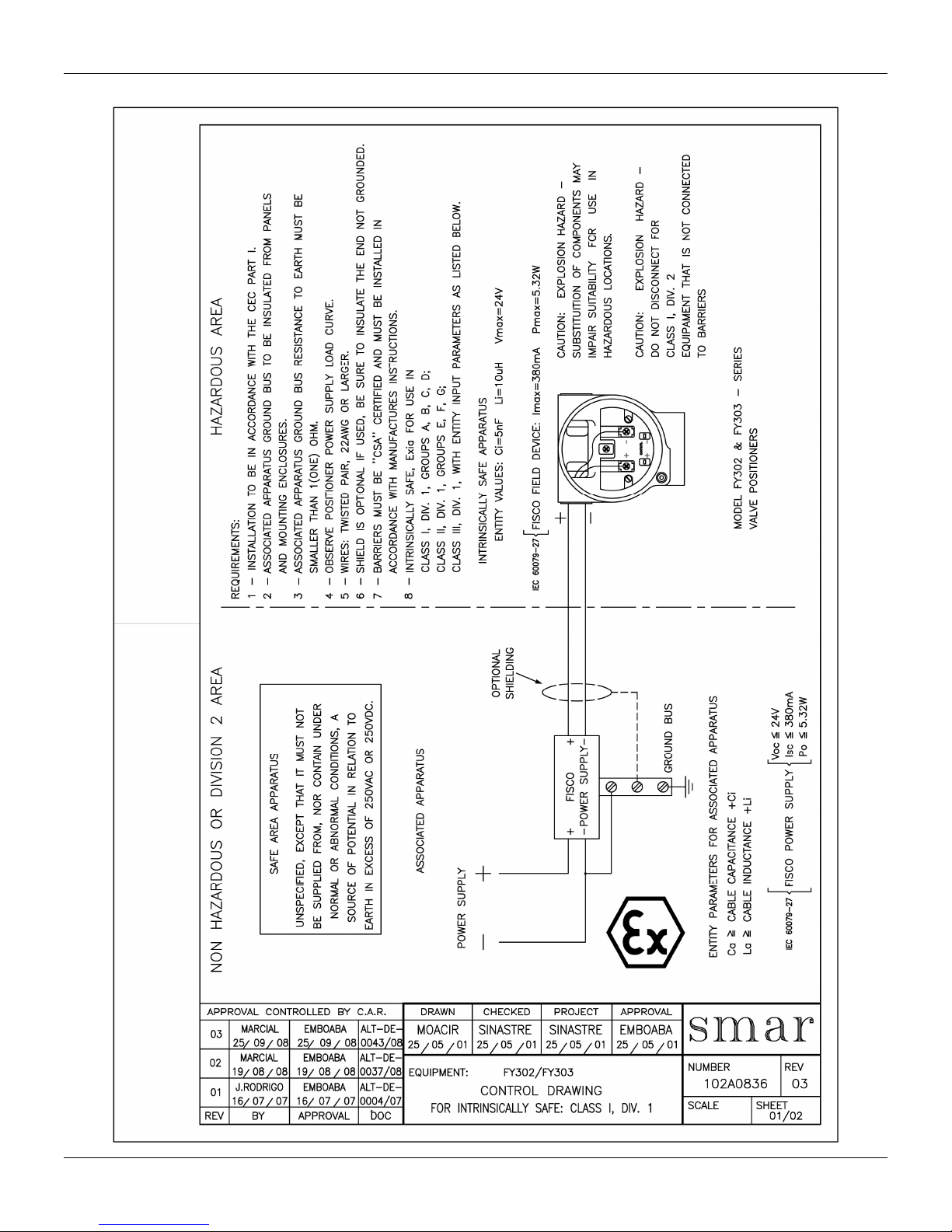
H[525"⁄"Qrgtcvkqp."Ockpvgpcpeg"cpf"Kpuvtwevkqpu"Ocpwcn"
CSA (Canadian Standards Association)
C0:"
Page 97
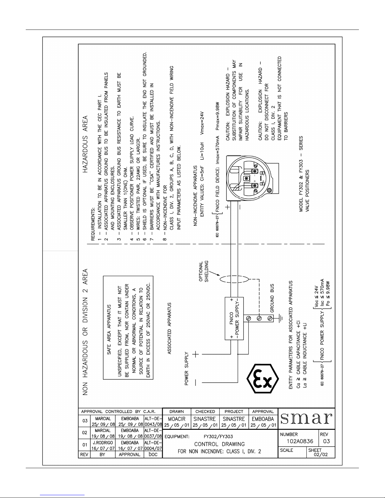
Egtvkhkecvkqpu"Kphqtocvkqp"
C0;"
Page 98

H[525"⁄"Qrgtcvkqp."Ockpvgpcpeg"cpf"Kpuvtwevkqpu"Ocpwcn"
C032"
Page 99
Crrgpfkz"D"
Model: FY290 ( ) Firmware Version: ______________________ FY301 ( ) Firmware Version: ______________________
FY302 ( ) Firmware Version: ______________________ FY303 ( ) Firmware Version: ______________________
FY400 ( ) Firmware Version: ______________________
Serial Number: _______________________________________ Sensor Number: ________________________________________
TAG: _______________________________________________________________________________________________
Remote
Position
Sensor?
Pressure
Sensor?
Action: Rotary ( ) Linear ( )
Travel: 15 mm ( ) 30 mm ( ) 50 mm ( ) 100 mm ( ) Other: ________ mm
Configuration: Magnetic Tool ( ) Palm ( ) Psion ( ) PC ( ) Software: _________ Version: __________
Type: Valve + Actuator ( ) Pneumatic Cylinder (ACP) ( ) Other:________________________
Size: _______________________________________________________________________________________________
Travel: _______________________________________________________________________________________________
Manufacturer: _______________________________________________________________________________________________
Model: _______________________________________________________________________________________________
Conditions: Dry and Clean ( ) Oil ( ) Water ( ) Other: ____________________________________
Work Pressure: 20 PSI ( ) 60 PSI ( ) 100 PSI ( ) Other: ________ PSI
Hazardous Area
Calssification
Interference
Types
______________________________________________________________________________________________________________
______________________________________________________________________________________________________________
______________________________________________________________________________________________________________
______________________________________________________________________________________________________________
Adjustment ( ) Cleaning ( ) Preventive Maintenance ( ) Update / Up-grade ( )
Other: _________________________________________________________________________________________________________
Company: _____________________________________________________________________________________________________
Contact: ______________________________________________________________________________________________________
Title: _________________________________________________________________________________________________________
Section: ______________________________________________________________________________________________________
Phone: __________ _________________________ __________ _________________________ Extension:____________________
E-mail: _________________________________________________________________________ Date: ______/ ______/ __________
Yes ( ) No ( )
Yes ( ) No ( )
Non-Classified ( ) Chemical ( ) Explosive ( ) Other: ________________________________
Vibration ( ) Temperature ( ) Eletromagnetic ( ) Others:
Other:
SRF – Service Request Form
FY Positioner
GENERAL DATA
FINAL CONTROL ELEMENT DATA
AIR SUPPLY
PROCESS DATA
_______________________________
SITUATION DESCRIPTION
SERVICE SUGGESTION
USER INFORMATION
Further information about address and contacts can be found on www.smar.com/contactus.asp.
For warranty or non-warranty repair, please contact your representative.
D03"
Page 100

H[525"⁄"Qrgtcvkqp."Ockpvgpcpeg"cpf"Kpuvtwevkqpu"Ocpwcn"
Tgvwtpkpi"Ocvgtkcnu"
Should it become necessary to return the positioner and/or configurator to SMAR, simply contact
our office, informing the defective instrument serial number, and return it to our factory.
In order to speed up analysis and solution of the problem, the defective item should be returned with
a description of the failure observed, with as much details as possible. Other information concerning
the instrument operation, such as service and process conditions, is also helpful.
Instruments returned or to be revised outside the guarantee term should be accompanied by a
purchase order or a quote request.
D04"
 Loading...