

Page 1
, ,
Foundation Fieldbus www.esma-rt.ru
Page 2

smar
www.e
sma-rt.ru
Specifications and information are subject to change without notice.
Up-to-date address information is available on our website.
web: www.
esma-rt.ru
Page 3

Introduction
INTRODUCTION
FOUNDATION fieldbus (FF) is an open architecture to integrate information, whose main objective is
to interconnect control devices and industrial automation, distributing the control functions for the
network and supplying information to all the layers of the system.
The F
OUNDATION fieldbus technology substitutes with advantages the 4-20mA + HART traditional,
technology making possible the bi-directional communication among the devices in a more efficient
way.
This technology is much more than a protocol of digital communication or a local network to field
instruments. It includes several technologies, such as distributed processing, advanced diagnosis
and redundancy. A FOUNDATION fieldbus system is heterogeneous and distributed, composed b y
field devices, configuration and supervision software, communication interfaces, po wer suppl y and
by its own physical network that interconnects them.
One of the functions of the field devices is to execute the user application of control and superv ision
distributed by the network. This is the big difference between FOUNDATION fieldbus and other
technologies that depend on a central controller to execute the algorithms.
Compared to other systems, F
related to the process, but also diagnostics of sensor and actuator, electronic components,
performance degradation, among others. Besides, there are other outstanding characteristics:
Intrinsic safety for use in hazardous areas, with power supply and communicati on on the same
wire pair;
Topology in bus or tree, with support to multiple masters in the communication bus;
Deterministic (foreseeable) behavior, even with redundancy in several levels;
Distribution of the control functions among the devices (distributed control);
Standardized interfaces among the devices that facilitate interoperability;
Application modeling using functional blocks language.
This manual presents details of fieldbus installation, besides common configuration points of Smar.
series 302 F
Whenever possible, consult standards, physical r egulations, as well as the safety practices of each
area.
Act with safety in the measurements, avoiding contact with terminals and wiring, because high
voltage can be present and cause electric discharge. Remember that ea ch plant and system has
their own safety details. To find out about them before beginning the work is very important.
To minimize the risk of potential problems related to safety, follow the safet y standards applica ble to
the local classified areas regulating the installation and operation of the devices. These standar ds
vary area by area and are constantly updated. It is the user's responsibility to determine which
standards should be followed in your applications and to guarantee that e ach equipment is installe d
accordingly.
Inadequate installation or use of a device o n non-recommended applications can harm t he system
performance and consequently the process, besides being a source of d anger and accidents. Due
to this, it is recommended using only trained and qualified professional s for installation, operation
and maintenance.
Damages caused to the devices by inadequate installations or use in the wrong applications are
not covered by warranty.
OUNDATION fieldbus devices.
OUNDATION fieldbus allows the access to many variables, not only
NOTE
Get the best results from the Foundation
instructions.
fieldbus Series 302 by carefully reading these
III
Page 4

GENERAL - Installation, Operation and Maintenance Manual
This Manual is compatible with version 3.XX, where 3 denote soft ware version and XX software
release. The indication 3.XX means that this manual is compatib le with any release of Series 302
field devices with software version 3.
ATENTION
IV
Page 5

Table of Contents
TABLE OF CONTENTS
SECTION 1 - INSTALLATION.....................................................................................................................1.1
NETWORK WIRING..................................................................................................................................................1.1
FOUNDATION FIELDBUS PHYSICAL MEDIUM, CABLING AND INSTALLATION..................................................1.2
FOUNDATION FIELDBUS H1 NETWORK ............................................................................................................................1.2
FOUNDATION FIELDBUS HSE NETWORK..........................................................................................................................1.3
RESUMO DAS CARACTERÍSTICAS DA REDE H1 E HSE...................................................................................................1.4
GENERAL NOTIONS OF INSTALLATION FOR THE H1 NETWORK ...................................................................................1.4
MAIN ELEMENTS OF THE FOUNDATION FIELDBUS H1 NETWORK ................................................................................1.4
SECTION 2 - OPERATION..........................................................................................................................2.1
LCD INDICATOR.......................................................................................................................................................2.1
INDICATION OPERATION........................................................................................................................................2.2
BASIC DETAILS OF THE SYSCON USE..................................................................................................................2.2
INTRODUCTION....................................................................................................................................................................2.2
COMMUNICATION ................................................................................................................................................................2.3
SUPPORT TOOL ...................................................................................................................................................................2.3
LIVE LIST...............................................................................................................................................................................2.3
BLOCK LIST...........................................................................................................................................................................2.4
USING THE ASSETVIEW ASSET MANAGER..........................................................................................................2.5
VISUALIZING THE DEVICE PAGE...........................................................................................................................2.5
CALIBRATION........................................................................................................................................................................2.5
CONFIGURATION .................................................................................................................................................................2.5
DIAGNOSTICS.......................................................................................................................................................................2.6
IDENTIFICATION...................................................................................................................................................................2.6
DEVICE VIEW........................................................................................................................................................................2.6
DISPLAY ................................................................................................................................................................................2.6
RECONCILIATION.................................................................................................................................................................2.6
SECTION 3 - LOCAL ADJUSTMENT SETTING.........................................................................................3.1
CREATING DEVICES............................................................................................................................................................3.1
CREATING A DEVICE FROM A TEMPLATE.........................................................................................................................3.2
CHANGING THE DEVICE ATTRIBUTES ..............................................................................................................................3.3
MASTER BACKUP DEVICE...................................................................................................................................................3.4
DELETING DEVICES.............................................................................................................................................................3.5
ORDERING DEVICES ...........................................................................................................................................................3.6
MOVING DEVICES................................................................................................................................................................3.6
DEVICE EXCHANGE.............................................................................................................................................................3.6
FUNCTION BLOCKS.................................................................................................................................................3.9
DISPLAY TRANSDUCER........................................................................................................................................3.10
LOCAL PROGRAMMING TREE..............................................................................................................................3.11
DISPLAY CONFIGURATION USING SYSCON......................................................................................................3.12
USING LOCAL ADJUSTMENT................................................................................................................................3.14
LOCAL ADJUSTMENT METHODOLOGY...............................................................................................................3.15
HOW TO CONFIGURE A TRANSDUCER BLOCK .................................................................................................3.16
CHANNELS.............................................................................................................................................................3.16
CALIBRATION.........................................................................................................................................................3.16
SECTION 4 - MAINTENANCE.....................................................................................................................4.1
GENERAL..................................................................................................................................................................4.1
TROUBLESHOOTING ...........................................................................................................................................................4.1
PROCEDIMENTO DE INICIALIZAÇÃO DE FÁBRICA (FACTORY INIT)..................................................................4.2
RETURNING SMAR PRODUCTS AND/OR MATERIALS.........................................................................................4.3
SECTION 5 - UNITS CODES.......................................................................................................................5.1
APPENDIX A – SMAR WARRANTY CERTIFICATE ................................................................................. A.1
V
Page 6

GENERAL - Installation, Operation and Maintenance Manual
VI
Page 7
Section 1
Network Wiring
INSTALLATION
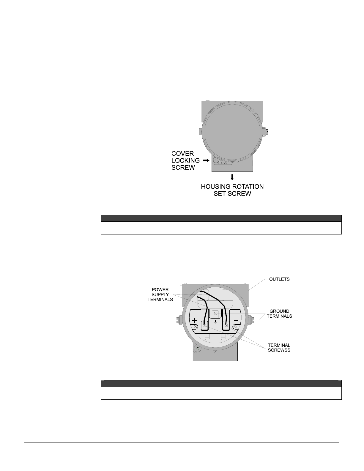
Access the wiring block by removing the Electrical Connection Cover. T
closed by the cover locking screw; to release the cover, rotate the locking screw clockwise. (See
Figure 1.1).
his cover can be locked
Figure 1.1 - Housing Adjusting Screw and Cover Lock
NOTE
The covers should be closed by hand completely, until the O’Ring is tight. For more safety, do not
use tools in this operation.
Cable access to wiring connections is obtained by tw
means of code-approved sealing methods. The unused outlet connection should be plugged
accordingly.
The wiring block has screws on which fork or ring-ty
Figure 1.2 - Wiring Block
Due to each device particularity, check the electric connection block in the specific equipment
manual. The LD302 was used above as example.
For convenience there are two ground terminals: one inside the cover and one external, located
close to the conduit entries. More details are described in Shield and Grounding item.
Avoid routing signal wiring close to power cables or switching equipment.
o outlets. Conduit threads should be sealed by
pe terminals can be fastened. See Figure 1.2.
NOTE
1.1
Page 8
Series 302 FIELDBUS FOUNDATION – Installation, Operation and Maintenance Manual
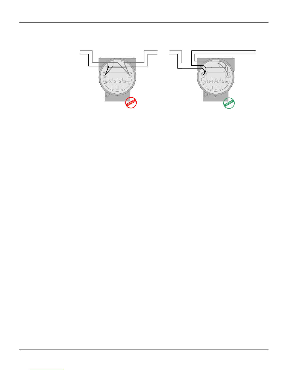
The Series 302 devices are protected against reverse polarity, and can withstand up to 35 VDC
without damage.
The Figure 1.3 show as to connect a device in a fieldbus network.
Figure 1.3 – Connecting a device to the Fieldbus network
Foundation Fieldbus Physical Medium, Cabling and Installation
The standard first versions specify two options for the phy
of 31.25 Kbits/s is oriented basically to field device (transmitters, valve positioners, etc), and it can
be used in areas requiring intrinsic safety (explosive atmospheres). The H2, with rate from 1 to 2.5
Mbps, would be used to integrate controllers and more complex devices.
Due to the fast technological evolution, the H2 w
Mbps. Therefore, for field devices connection there is the FOUNDATION fieldbus H1, with physical
layer based on ISAS50.02-1992 or IEC61158-2:2000. For connection among PLCs, Linking
Devices, Gateways and PCs, there is the FOUNDATION fieldbus HSE, based on Ethernet
(IEEE802.3-2000, ISO/IEC8802.3-2000).
as substituted by the HSE that uses Ethernet at 100
Foundation Fieldbus H1 Network
A Fieldbus network is composed by several H1 buses, connected to each other by bridges or
Foundation Fieldbus Linking Devices that connect the H1 networks to the HSE backbone.
According to definitions, each H1bus can hold, theoretically, up to 32 devices not pow
bus. In practice, there may be up to 12 field devices powered by the bus and other 20 devices not
powered by the bus, each one with a single logical address in the network (1 Byte). This limit is due
mainly to the electric characteristics of the power supply and the current consumption of the devices.
In practical terms, it is recommended that the total number of devices doesn't surpass 10, because
the network traffic tends to become very high and there may be performance degradation. In
classified areas, it is recommended to analyze the output of the intrinsic safety barrier to define the
number of devices. With the FISCO concept, there may be a larger amount of devices per segment.
The wiring length can reach 1900 m, and up to 4 repeaters can be used.
sical layer: H1 and H2. The H1, with rate
ered by the
Figure 1.4 –Simplicity of the Foundation Fieldbus H1 Physical
1.2
Layer (IEC61158-2)
Page 9
Installation
The physical medium is a shielded twisted pair cable. T
done by the same pair, needing at least 9 V in the terminal of the device to energize it. It is
recommended that this tension be larger than 10 V, enough to keep a complete communication
signal (0.75 Vpp to 1 Vpp), taking into account the cable tension loss, the bus total consumption,
etc.
A modified Manchester code is used, producing a signal
components. That code brings other advantages: frame formation (special characters for start
delimiter and end delimiter), formations of different physical topologies (bus and stars) and the
warranty that the data and the clock arrive at the same time (synchronous serial signal).
The signal modulation is done by the variation of a current of 10 mA to 31.25 Kbit/s in an equivalent
load of 50 Ω
32 Vdc).
Both the current and the operation
device model (consult the respective manual). For Smar devices, each fieldbus device consumes
about 12 mA.
, resulting in a modulated voltage of 0.75 Vpp to 1 Vpp overlapping the bus voltage (9 –
minimum voltage can vary according to the manufacturer or
he power supply and the communication are
with null average value, that is, without DC
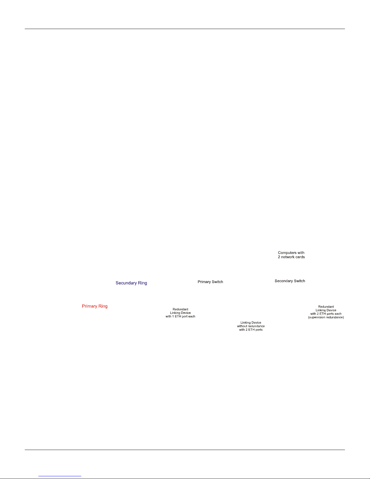
Foundation Fieldbus HSE Network
This network is based on the same Ethernet phy
equipments for industrial applications, be it with adequate temperature range (-40 to 85 ºC), be with
specific functions for real time data communication.
The communication and synchronism characteristics among the devices
the H1, and the main differences are in determinism. Through the use of the Ethernet network in the
Foundation Fieldbus HSE network it is possible to build an industrial control network with shelf
components, independently of the manufacturer.
The HSE standard uses 100 Mbps, but nothing opposes the devices from communicating at higher
rates, like 1 Gbps or even the new
10 Gbps standard.
sical layer. Several manufacturers offer specific
are basically the same as
Figure 1.5 –Usual Topologies of the Foundation Fieldbus HSE Network: Ring and Stars, both Redundant
1.3
Page 10
Series 302 FIELDBUS FOUNDATION – Installation, Operation and Maintenance Manual
Summary of characteristics H1 and HSE Networks
The Table 1.1 show a summary of characteristics presents in H1 and HSE networks.
H1 HSE
Baud Rate 31.25 Kbits/s 10 Mbit/s or
Distance (segment) 1.900 m 100 m
Two wires Yes Não
Multidrop Yes No (UTP)
Bus-power Yes No
Intrinsically Safe Yes No
Redundance No Yes
Deterministic Yes Yes (with switches)
Table 1.1 - Summay of the Characteristics of the Physical Layer FF
General Notions of Installation for the H1 Network
The H1 network represents a great digital communication solution for the factory ground, both in
safe as classified areas. It accepts topologies in bus, ring, star or tree,
1900 m without repeater.
Using up to 4 repeaters it is possible to cover a radius of approximately
amount of devices in each H1 segment depends on the type of application, the length of the cables
and even the performance wanted for the network.
100 Mbit/s
and even distances up to
10 km. The maximum
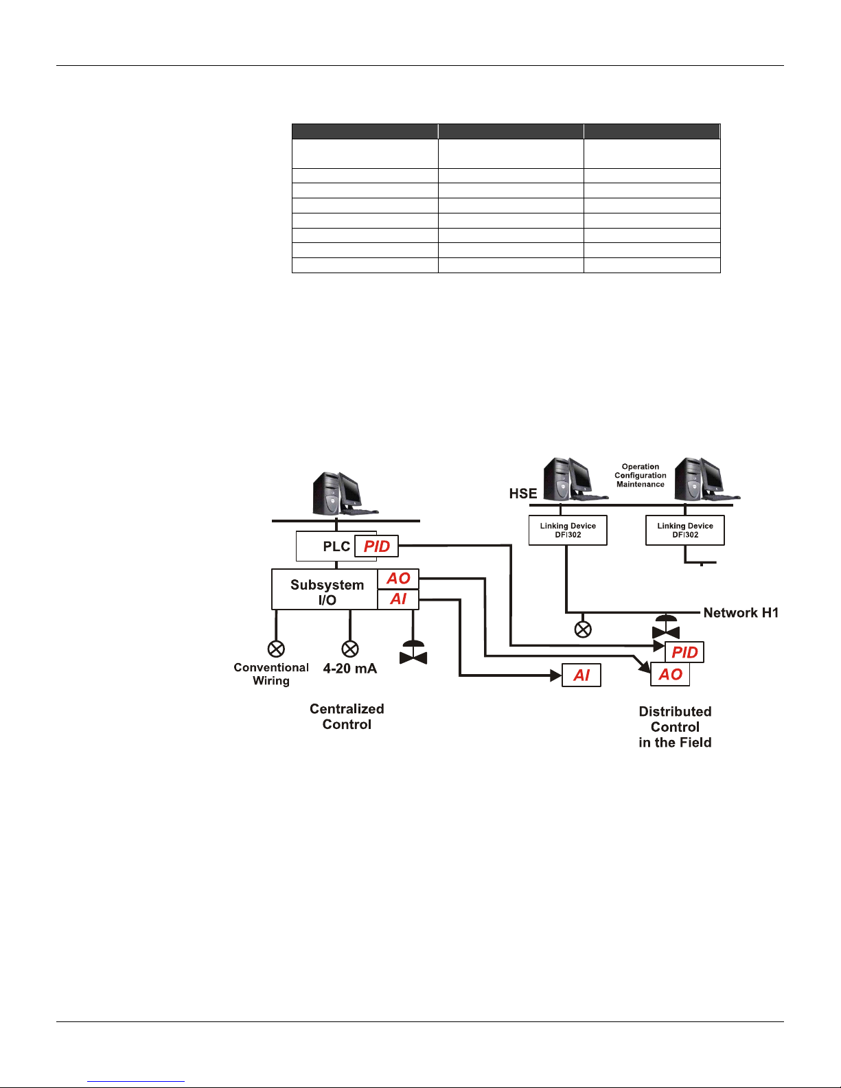
Figure 1.6 - Comparison of Wiring and Distribution of Control over the Network Devices
Main elements of the Foundation Fieldbus H1 Network
Cabling
The IEC61158-2 determines that the physical medium of the Foundation Fieldbus H1 network
should be a twisted pair cable. The properties of a field bus are determined by the electric conditions
of the cable used.
Although the IEC61158-2 doesn't specify
recommended, in order to guarantee the best communication conditions and distances involved.
1.4
the cable technically, the type A cable is highly
Page 11

Installation
L
L
B
L
B
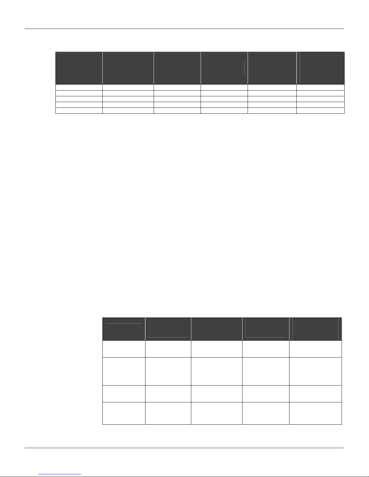
Table 1.2 presents in detail the specifications of the several cables at 25 ºC.
that most of the cable manufacturers recommend the operation temperature between -40 ºC and
+60 ºC. It is necessary to verify the critical points of temperature through where the cabling passes
and if the cable supports it. The type A cable resistance of 22 O/Km is valid at 25 ºC. For example,
the resistance of the type A cable to 50 ºC is 24.58 Ω/Km. That should be taken into account in hot
countries as Brazil.
Type A Type B Type C Type D
Cable Description
Nominal Driver Section
Area (of the)
(Resistance DC
Maximum) Maximum DC
Loop Resistance (loop)
Characteristic impedance
(to) at 31.25 KHz
Maxim Attenuation to 39
Maximum Unbalanced
Group Delay Distortion
Surface Covered by the
Total Cable Length and Distribution and Installation Rules
The total length of the H1 cable should be considered from the exit of the point of PSI
impedance – power supply with active impedance) until the most distant point of the segment,
considering the derivations. Remember that spurs smaller than 1 m don't enter in this total.
The cabling total length is the sum of the main bus trunk size plus all the spurs (branches larger than
1 m), and w
type A cable, it is a maximum 1000 m, considering that the spurs cannot exceed 30 m.
In installation and distributions terms avoid splices, in other w
specified conductive medium and a discontinuous length smaller than 1 m, for example: shielding
removal, wire diameter changes, connection to bare terminals, etc. In networks with total length
larger than 400 m, the sum of the lengths of all the splices should not surpass 2% of the total length
and also, in lengths smaller than 400 m, should not exceed 8 m.
A H1 segment maximum length, when using different cable ty
Where:
A
KHz
Capacitance
(7.9 to 39 KHz)
Shield
Recommendation for
Network Extension
(including spurs)
Table 1.2 – Characteristics of the Several Cables Used in Foundation Fieldbus H1
ith type A cable, the length is a maximum 1900 m in non-safety areas. In safe areas with
⎛
⎜
⎜
LA
⎝
: Length to the cableA;
B : Length to the cable
LC
: Length to the cable ;
Twisted Pair
wi
th Shield
2
0.8 mm
(AWG 18)
44 Ω/Km 112 Ω/Km 264 Ω/Km 40 Ω/Km
100 Ω ± 20% 100 Ω ± 30% ** **
3 dB/Km 5 dB/Km 8 dB/Km 8 dB/Km
2 nF/Km 2 nF/Km ** **
1.7 µsec/Km ** ** **
90% ** - -
1900 m 1200 m 400 m 200 m
⎛
LA
⎞
⎟
⎟
⎠
;
LB
⎜
+
⎜
LB
⎝
C
One or more total
isted pair with
tw
Shield
2
LC
LC
⎞
⎟
+
⎟
⎠
0.32 mm
(AWG 22)
⎛
⎜
⎜
⎝
Several twisted
ithout Shield
pair w
0.13 mm
(AWG 26)
ords, any part of the network with a
pes is limited by the following formula:
⎛
⎞
⎟
⎟
⎠
LD
⎜
+
⎜
maxmaxmaxmax
LD
⎝
It is worth to remind
Several non-
isted pair
tw
2
⎞
⎟
〈=
⎟
⎠
without Shield
(power supply
1
0.25 mm
(AWG 16)
2
D : Length to the cable ; D
: Maximum length allowed with the cable A(1900 m);
maxLA
maxLB : Maximum length allowed with the cable
: Maximum length allowed with the cable (400 m);
maxLC
: Maximum length allowed with the cable (200 m). D
maxLD
(1200 m);
C
1.5
Page 12
Series 302 FIELDBUS FOUNDATION – Installation, Operation and Maintenance Manual
(
+
=
〈
=
In relation to the spurs be attentive to the lengths of the same. T
repeaters, if any, should comply with the Table 1.3. In classified areas the maximum spur is 30 m.
Total H1
devices per
segment
1-12 120 90 60 30 12 x 120 =1440
13-14 90 60 30 1 14 x 90 = 1260
15-18 60 30 1 1 18 x 60 = 1080
19-24 30 1 1 1 24 x 30 = 720
25-32 1 1 1 1 1 x 32 = 32
Spur length with
1 device
Spur length
with 2 devices
Spur length
with 3 devices
Table 1.3 - Spur x Number of H1 Devices
Note: The cable capacitance limit should be considered w
hen the effect in the spur signal is smaller
than 300 m and resembles capacitor. In the absence of the cable manufacturer´s data, a value of
0.15 nF/m can be used for fieldbus cables.
)
*
CdCsLsCt
Where:
Ct
: Total capacitance in nF;
LS
: Spur length in m;
Cs
: Wire capacitance per segment in nF (Standard – 0.15);
Cd
: Foundation fieldbus device capacitance;
The attenuation associated to this capacitance is 0.035 dB/nF. Therefore, the total attenuation is:
Then, 14 dB will allow the minimum necessary signal to detect it w
There are some rules to follow in terms of cabling and separation from other cables, be it for signals
or potency
. Use preferably trays or metal ducts, observing the distances according to Table 1.4.
Never pass the fieldbus H1cable beside high voltage lines because the induction is a noise source
and it can affect the communication signal. Furthermore, the fieldbus signal should be isolated from
noise sources, as power cables, motors and frequency. It is recommended to put in separated
channels and ducts. The ideal is to use aluminum ducts, with internal and external eletromagnetic
shield. The Foucault currents are practically immune, due to the aluminum good electric
conductivity. Remember that the crossing of cables should be at 90º angle.
Cabo de
comunicação
Fieldbus
Cabos com e
sem shield:
60Vdc ou
25Vac e
< 400Vac
Cabos com e
sem shield:
> 400Vac
Qualquer cabo
sujeito à
exposição de
raios
Fielbbus
Communication
Cables
10 cm 20 cm 50 cm
10 cm 10 cm 50 cm
20 cm 10 cm 50 cm
50 cm 50 cm 50 cm
Cables with and
without shield: 60
Vdc or 25 Vac and
< 400 Vac
Table 1.4 –Minimum separation distances between Cables
he amount of devices, < including
Length
Spur length
with 4 devices
Considering the
Maximum
Amount of
Spurs (m)
dBnFdBLsCtA 14/035.0**
ith integrity.
Cables with and
without shield:
> 400 Vac
Any cable subject
to the (exhibition of
rays) exposition to
lightning
1.6
Page 13
Installation
H1 Network Terminators
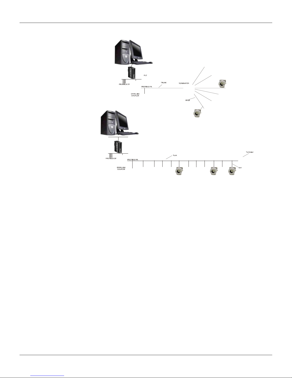
Two bus terminators should be connected to the H1 network, being one in the PSI output and the
other in the last device (usually the most distant from the PSI), depending on the adopted topology.
If in the cabling distribution there is a junction box in the end of the main trunk w
ith several spurs, the
field terminator should be placed in this point, to facilitate the maintenance when removing devices.
Check the correct connection of the terminator, reminding
that the lack of terminators allows
communication intermittency, once there is no impedance match and there is reflection signal
increase.
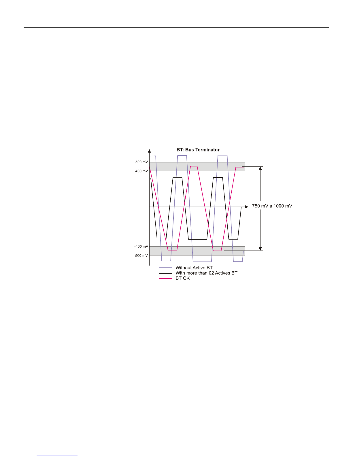
The lack of a terminator or its connection in the incorrect point al
so degrades the signal, once it will
also be part of the cabling as an antenna. Its lack can increase the signal in more than 70% and an
additional terminator can increase the sign up to 30%. The attenuation and intermittency can
generate communication failure.
The H1 network terminator is formed by a resistor of 100 ± 2% and a capacitor
of 1 µF ± 20% in
series.
Figure 1.7 –Typical H1 Wave Forms Acco
rding to the Termination
1.7
Page 14
Series 302 FIELDBUS FOUNDATION – Installation, Operation and Maintenance Manual
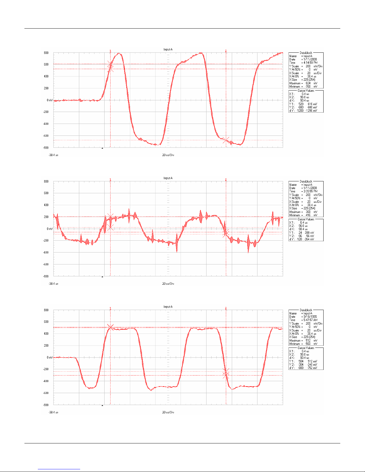
Following, the real waves forms related to the three cases mentioned on Figure 1.7.
Figure 1.8 –Wave form without Active BT
Figure 1.9 –Wave form with more than 2 Active BTs
1.8
Figure 1.10 –Wave form with Correct BT
Page 15
Installation
Check the position of the terminators in the following topologies.
Figure 1.11 - Position of Terminators in Tree or Star Topologies and on the Bus
Power Supply
The power supply usually has an output of 24 Vdc with capacity of a few ampéres. The power supply
can operate in redundant mode and it should failure indication and protection against surges,
transients and short circuits. Smar makes the DF52 power supply that meets these characteristics.
In terms of power supply signal, consider as acceptable values in practice:
12 to 32 Vdc in the PSI output (Active Impedance)
•
• Ripple
(mV):
< 25: excelent;
25 < r< 50: ok;
50 < r < 100: acceptable;
> 100: unacceptable.
In terms of communication signal, consider as acceptable values in practice:
•
750 to 1000 mVpp: ok;
> 1000 mVpp: Very high. A terminator may be lacking.
Some barriers and segment protectors, like spur guards, have high impedance in series and can
produce signals up to 2000 mV and even allow
the appropriate operation.
• < 250 mVpp: Very low. It is necessary to verify if there is more than 2 active terminators, power
supply, etc.
Some devices have polarity, others not, so it is very important to
assure the correct polarity of the
devices. All the devices are connected in parallel, that is, all the negative terminals together and all
the positive terminals together. The use of colored wires codified is recommended to distinguish the
positive from the negative.
Active Impedance
The active impedance avoids that the pow
er supply low impedance lessens the communication
signal of the bus, allowing the feeding to be supplied in the same wire pair.
1.9
Page 16
Series 302 FIELDBUS FOUNDATION – Installation, Operation and Maintenance Manual
It works as low impedance for DC and high impedance for AC communication signal and may have
an additional internal terminator activated by
a frontal key. The active impedance is fundamental for
the network correct operation.
The Foundation Fieldbus impedance is on a device of non-isolated,
complying with the IEC61158-2 standard. This device has an output impedance that works in
parallel with the two bus terminators (a resistor of 100
to the pattern and results in purely
resistive line impedance for a wide frequency range. The Smar
Ω in series with a capacitor of 1 µF) assisting
DF49 module has two channels and the DF53 module four channels.
Repeaters H1
The passive repeater increases the H1 segment range of 1900 m by
repeaters may be used with 8-bit preamble or a maximum of 8 repeaters with 16-bit preamble. A
maximum of 4 repeaters. It is usually allowed.
As the repeater isolates the communication signal
and the power supply, it is possible to connect
devices that drain more current from the bus or even to create new segments starting from the same
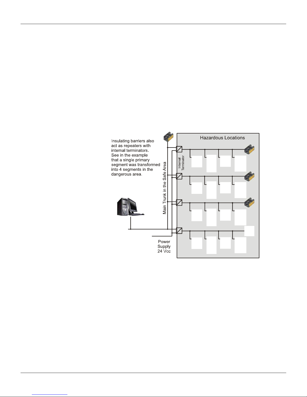
main bus (Figure 1.12). Smar offers the RP302 repeater, as well as the DF47 model that works both
as repeater and intrinsic safety barrier.
active impedance control,
amplifying its signal. Up to 4
Intrinsic Safety Barrier
The intrinsic safety barrier has the primary function to limit the energy
circulates for the classified areas.
A classified area is that whose atmosphere is potentially
repeats the FF signal, allowing several segments on the dangerous side to be connected to the safe
side. See Figure 1.12. The Smar offers the model DF47, which works as repeater and intrinsic
safety barrier, as well as the SB302 model, which is an isolated barrier.
Derivation Box
It allows the connection and disconnection of devices without interrupting the continuity
increasing the plant availability and simplifying maintenance. It reduces start-up time, stoppage time
and cabling costs.
In the Smar JM400 model, the weather-proof and explosion-proof housing prevents w
from reaching the electric connections (IP66/68). Its cover lock mechanism doesn’t require specific
support. See Figure 1.13 and 1.14.
1.10
Figure 1.12 - Isolation Provided by the Barrier
available in the bus that
explosive. The barrier usually isolates and
of the bus,
ater, oil or dirt
Page 17

Installation
Figure 1.13 - Field Network with Derivation Box
Figure 1.14 –Field Network with Derivation Box
The FISCO Concept Intallation
The FISCO model (Fieldbus Intrinsically Safe Concept) has the following characteristics:
a) There is only one active element - the pow
er supply - in the field bus, located in the non-classified
area;
b) The other devices in the classified area are passive;
c) Each field device should have a minimum consumption of 10 mA;
d) In Ex ia areas the maximum bus length should be 1000 m and in Ex ib, 5000 m;
e) Concerning cables observe the follow
R´:15 to 150 Ω/km;
L´: 0.4 to 1 mH/km;
C´: 80 to 200 nF/km.
ing parameters:
Type A cable: 0.8 mm² (AWG 18)
a) Concerning termination:
R = 90 to 100 Ω;
C = 0 to 2.2 µF.
1.11
Page 18

Series 302 FIELDBUS FOUNDATION – Installation, Operation and Maintenance Manual
The FISCO concept was optimized so that a larger number of field devices is allowed according to
the bus length, taking into account the cable variation characteristics (R', L',C ') and terminators that
assist categories and groups of gases with a simple evaluation of the installation involving intrinsic
safety. Thus, it increased the current capacity per segment and facilitated the evaluation for the
user. Besides, when acquiring certified products, the user doesn't need to worry with calculations,
even in substitution of an operation.
The FISCO model represents a fast and easy way to project, install and operate H1 netw
installations on classified areas. The main idea is to supply more current to the H1 segment,
enabling among other advantages the connection of a greater number of equipments, when
compared to a conventional intrinsically safe installation. In summary, just follow the requirements
below:
Use certified and approved devices for FISCO applications;
•
Check the parameters of each device (U
•
Observe the parameters of the used cables carefully (R, L, C). Use type A cable
•
To observe the correct use of the terminators;
•
Do not exceed the maximum length allowed for the cabling.
•
, Ii, Pi): U0<Ui, I0<Ii, P0<Pi;
i
The main advantages when using a FISCO installation are:
•
Plug&Play actions in hazardous areas;
The system certification is not mandatory, but is up to user discretion;
•
The expansion of the application is very simple;
•
It is possible to connect the maximum number of devices in the classified area;
•
The installation costs are reduced;
•
There is no need for parameter recalculation when changing the devices.
•
FNICO
A new concept that also appears on the scene is F
NICO (Fieldbus Nonincendive Concept), which is
similar to the FISCO, but limited for use in Zone 2. Both concepts, FISCO and FNICO, are turning
the fieldbus more attractive for use in hazardous areas.
FNICO is allowed in North America countries or those based on standards of this region. T
concept considers:
• Input capacitance/inductance;
Maximum cabling and spurs;
•
And the following:
•
Vmax of each field device > Voc of the Repeater;
Imax of each field device > Ioc of the Repeater;
•
Pmax of each field device > Poc of the Repeater.
•
Repeaters with 215 mA of capacity are common.
Transient Supressor
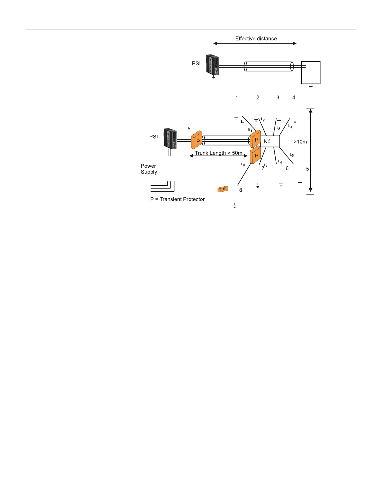
Whenever having an effective distance larger than 100 m on the
position between two grounded points, the use of transient protectors is recommended, on the
distance initial and final points. On the horizontal, its use is recommended between 50 and 100 m.
The transient protector should be installed immediately
after the PSI, before each device and also in
the junction box. In classified areas, the use of certified protectors is recommended. See Figure
1.15.
orks in
his
horizontal or 10 m on the vertical
1.12
Page 19
Installation
Figure 1.15 – Effective Distance in
a Cable Distribution
Topologies
In relation to topology, there are the following models: Star or T
1.16). In practice, there is usually a mixed topology.
ree, Bus and Point-to-point (Figure
Shield and Grounding
When considering shielding and grounding in field bus, the following should be taken into account:
Electromagnetic
Protection against explosion;
Protection of people.
Figure 1.16 – Examples to the Fieldbus Topology
compatibility;
1.13
Page 20
Series 302 FIELDBUS FOUNDATION – Installation, Operation and Maintenance Manual
ç
S
T
According to the IEC61158-2, to ground means to be permanently
sufficiently low impedance and with enough conduction capacity to prevent any voltage to cause
damages to equipments or people.
Voltage lines with 0 V should be connected to the
ground and be galvanically isolated from the bus.
The purpose of grounding the shield is to avoid high frequency noises.
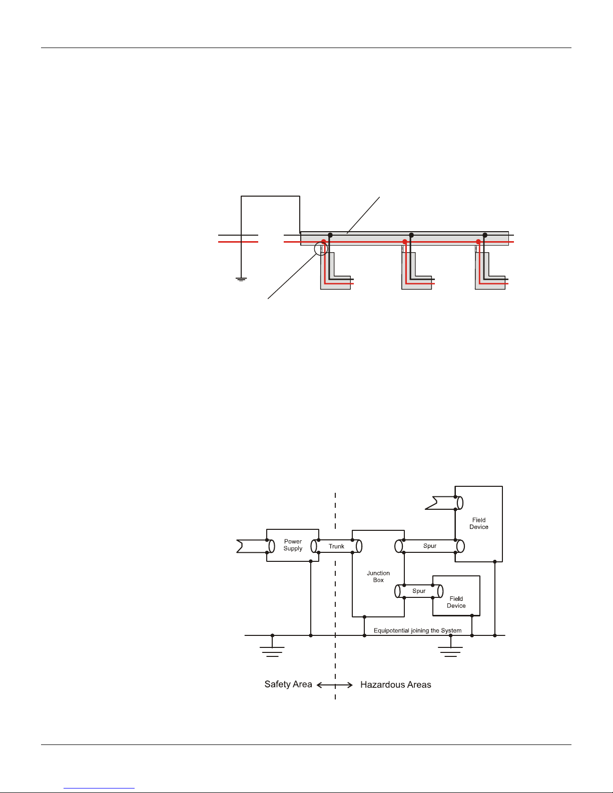
Preferably, the shield should be grounded in two points, in the beginning and the
long as there is no potential difference between these points, allowing the existence of loop current
and access to it. In practice, when this difference exists, the shield should be grounded in a single
point, in other words, at the power supply or the intrinsic safety barrier. The continuity of the cable
shield must be kept in more than 90% of the cable total length. See the Figure 1.17.
hield
connected to the ground through
end of the bus, as
B
PS
24 V
PSI
Shield do tronco e
das deriva
ões unidos
Figure 1.17 – Shield Grounding
The shield should cover the electric circuits completely
through the connectors, couplers, splices
and distribution and junction boxes.
The shield should never be used as a signal driver. T
he shield continuity should be checked until the
last fieldbus device on the segment, and the connection and finishing inspected, because the shield
should not be grounded to the equipment housing.
In classified areas, if a potential equalization betw
een the safe area and the hazardous area would
not be possible, the shield should be connected directly to the ground (Equipotencial Bonding
System) only on the dangerous area side. In the safe area, the shield should be connected
preferably through a ceramic capacitive coupler, like a solid dielectric capacitor, C =10 nF, isolation
voltage ≥ 1.5 kV). See Figures 1.18 and 1.19.
1.14
Figure 1.18 – Ideal Combination of Shield and Grounding
Page 21
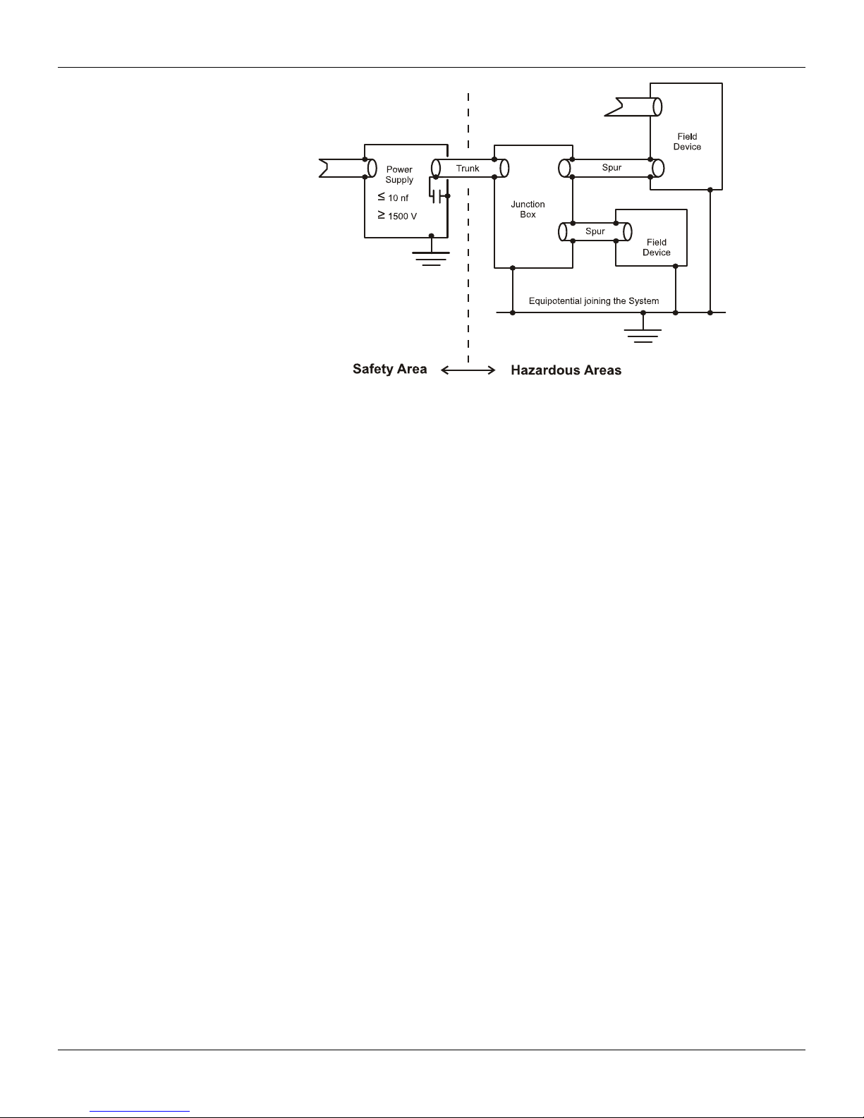
Installation
Figure 1.19 – Capacitive Grounding
IEC61158-2 recommends the complete isolation. This method is
used mainly in the United States
and in England. In this case, the shield is isolated from all the grounds, except the negative ground
of the power supply or of the intrinsic safety barrier on the safe side. The shield has continuity from
the PSI output, through the junction and distribution boxes and reaches the equipments. The
equipment housings are grounded individually on the non-safety side. This method has the
disadvantage of not entirely protecting the signals from the high frequency signals and, depending
on the cable topology and length; in some cases it can generate communication intermittency. Metal
ducts are recommended in these cases.
Another complementary form would be to ground the junction boxes and the equipment housings in
an equipotencial ground line on the non-safety
side. The grounds on the non-safety side and on the
safe side are separate.
The multiple grounding conditions are also common, w
ith more effective protection from high
frequency and electromagnetic noises. This method is preferentially adopted in Germany and some
countries in Europe. In this method, the shield is grounded on the negative ground point of the
power supply or the intrinsic safety barrier on the safe side, in addition to the junction boxes ground
and in the equipment housings and these are also grounded on the non-safety side. Another
complementary condition would be the grounds being connected together in an equipontencial
ground line, uniting the non-safety side to the safe side.
For more details, always consult the local safety
standards. Use the IEC60079-14 as reference for
applications in classified areas. See some ground and shield ways on Figure 1.20.
1.15
Page 22

Series 302 FIELDBUS FOUNDATION – Installation, Operation and Maintenance Manual
++∑
=
〈
Figure 1.20 – Several Grounding and Shield Ways
Quantity of Foundation Fieldbus Equipments in a H1 Segment
The amount of equipments (N) for segment is a function of the quiescent consumption of each H1
equipment, the involved distances (ty
the area classification, besides the FDE current (usually 0 mA, depending on the manufacturer). The
total segment current should be smaller than the one drained by the power supply. Smar devices
consume 12 mA.
Because:
Where:
: H1 segment current;
I
Seg
I∑ : Sum of the quiescent currents of all the devices in the H1 segment;
BN
I
: Additional current in case of failure, usually negligible;
FDE
I
: Recommended: 20 mA, rest current useful in case of expansion or change of manufacturer
FREE
I : Drained current.
C
Besides, it is recommended more than 9.0 V in the terminal block of the H1 device most distant from
the PSI to guarantee its pow
ering and correct communication:
pe A cable loop resistance: 44 O/km), the drained current, of
IIII
FREEFDEBNSeg
II
CSeg
1.16
Page 23

Installation
(
−
=
)
LRVV
*
CBN
Where:
V : Power supply output voltage;
C
: Loop resistance (Type A cable, R = 44 Ω/km);
R
: H1 Bus total length;
L
: Voltage in the terminal block of the H1 devices most distant from the PSI.
V
BN
Being . T
BN
his guarantees the powering of the last H1 device. Remember that the
VV
0.9〉
communication signal should range from 750 to 1000 mV.
Some junction boxes or short circuit protectors for
segments, called spur guards, are active and can
be powered through the H1 bus; hence, it should be included in the calculation of the total current.
Besides, each spur guard output has an allowed current limit that should be respected.
In classified areas follow
the established limits.
Foundation Fieldbus in Hazardous A
reas
According to the standards, the Foundation Fieldbus technology can be applied in hazardous areas
with the following characteristics:
Ex d: In this case choose the power supply Ex and conduits with Ex d approval;
•
Ex i: There are three options. The first involves the Ex-i concepts and the second a combination of
Ex and Ex i. T
he third option is the FISCO.
Summary of Classified Areas
Zone/ Explosion Group Identification Observation
Zone 0 (Ex ia) IIx
Zone 1
Explosion Group IIC IIC (Ex ia) IIC
Explosion Group IIB
Non -Ex Non-Ex
(Ex ia) IIx
(Ex ib) IIx
(Ex ia) IIC
(Ex ib) IIB
Devices installed in Zone 0 should operate in a
segment w
Devices installed in Zone 1 should operate in a
segment w
All the circuits connected to this segment should be
certified for “Ex ia” or “Ex ib” protection.
If the measures are taken in an IIC explosion group,
the devices and components should be certified for
the IIC.explosion group
For the IIB medium explosion group, both devices
and components can be certified for the IIC or IIB
groups.
Devices that are operating in a no-Ex segment
should not be installed in explosion-risk areas.
ith “Ex ia” protection.
ith “Ex ia” or “Ex ib” protection.
Table 1.5 - Summary of Classified Areas
Intrinsic Safety Definition
Intrinsic safety limits the equipment circuit energy, so that they
do not cause the ignition of
potentially explosive atmospheres even in the occurrence of failures that may produce sparks or
warm surfaces in contact.
As it deals with energy limitation,
this is an adequate technique for electronic equipments, typically
used in control and process instrumentation.
Foundation Fieldbus Technology and Intrinsic Safety
According to standards, 1 to 4 devices may be connected together in the hazardous areas, after the
Intrinsic Safety Barrier, and two more devices in the safe areas in the same bus.
With the energy limitations for each device in the hazardous area, some instruments w
ill need to be
run through other power supplies. Therefore, devices such as, process analyzers, of I/O
subsystems, magnetic or Coriolis effect meters can combine intrinsic safety with other installation or
contention techniques for protection against possible explosions.
1.17
Page 24

Series 302 FIELDBUS FOUNDATION – Installation, Operation and Maintenance Manual
It should be considered as intrinsic safety barrier the quantity of devices, the amount of cables and
the capacitance and inductance limit values for the Ex I installation.
Table 1.6 presents a brief comparison betw
een the FISCO and FNICO models and the entity model.
FISCO Entity Model FNICO
Cable Length
1000 m - ia (*)
1900 m 1000 m
5000 m - ib (*)
Maximum Spur
30 m(*)
Length
Cable and Length
Non-considered
Considered
Reactance
(*)Maximum analyzed length. It is possible (the) to use (of) a larger length.
Table 1.6 –FISCO vs. Entity Model
There is a set of rules for applications in hazardous areas that uses intrinsic
fieldbus technology refers to the lengths of the segments, limits of currents in the power supply and
parameters as capacitance and inductance, as well as parameters of equipment failures. The
FISCO method provides an easy implementation for applications intrinsically safe in fieldbus, giving
flexibility, operational safety to the applications and reducing installation costs, since one can handle
up to 10 devices in an Ex network. Besides, the possibility of online handling simplifies
commissioning, startup and maintenance. More power means more devices and less cables, hence
less barriers.
Equipments compliant to FISCO can be directly connected to
model. The reverse condition needs to be evaluated.
Following are described some key points that should be considered during the implementation,
involving classified areas and fieldbus:
• Which is the hazardous area. Remember that non-incendive is only allowed in Division 2 areas
and intrinsic safety equipment only in Division Div 1 and Division Div 2 areas);
• Which size and scalability required ;
• Will there be short circuit protection for the main trunk and the spurs?
• Which are the acceptable safety level and risks? (Projects involving intrinsic safety take into
account the components failure and allow maintenance while being powered, although without heat.
Conversely, non-incendive equipment doesn't allow maintenance being performed during powering
or even heat exchange.
• Are there limitations to shutdowns?
• Do the engineering and the maintenance teams have proven experience with hazardous and
classified areas?
• Do all the devices have certification compatible with the application?
• Are the facilities compliant to the area and country safety standards?
For more details consult IEC60079-27, “Fieldbus Intrinsically Safe Concept (FISCO)” and “Fieldbus
Non-Incendive Concept (FNICO)”.
Increasing the Reliability
There are several ways to increase the fieldbus network reliability. They are the following:
a) Power supply redundancy, according to Figure 1.21.
120 m
30 m(*)
Non considered
safety methods. The
IS networks based on the entity
1.18
Page 25
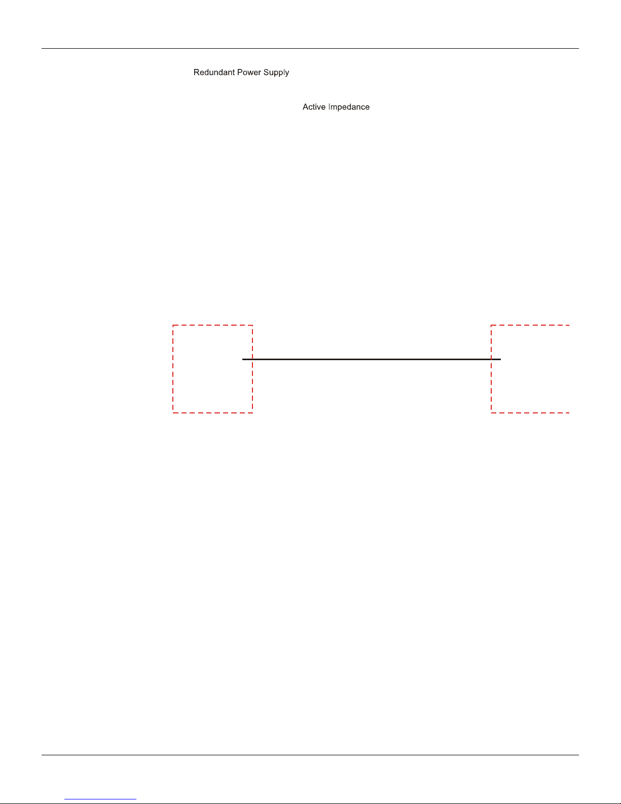
Installation
Figure 1.21 –Power Supply Redundancy
b) Double active power supplies and impedance, in case of a cabling break for: See F
Guaranteed power supply;
•
Non-guaranteed Integral communication;
•
Guaranteed failure position.
•
Figure 1.22 – Double power supplies and PSI
igure 1.22
1.19
Page 26

Series 302 FIELDBUS FOUNDATION – Installation, Operation and Maintenance Manual
1.20
Page 27

Section 2
LCD Indicator
OPERATION
The Series 302 devices have an optional digital LCD display that works as a local operator interfac e
for basic factory pre-programmed functions or for personalized user functions through the host
system remote tool in the engineering and/or maintenance station. To accomplish these
configurations through local adjustment, use the SD-1 magnetic tool for local adjustment.
In a more complete and friendly way, all confi
accomplished remotely, by using, for example, a configurador, an engineering or maintenance
console. For more details consult the Syscon network manual configurator or the AssetView asset
manager.
The configuration is composed of the autom
the tag attribution and the selection or instantiation of function blocks that will be executed inside the
device. And based on these, build the control strategies that it is made by selecting the blocks, interconnecting and adjusting the internal parameters in order to get the required operation.
The local and remote operation interfaces also ena ble monitoring the performance of the variables,
such
as process variables and setpoint. These variables de pend on their use and can be accessed
in a single communication.
The management of acyclic events is performed automatically. When alarms and other critical
events occur, the function block informs the user directly, without the need for the interface to
execute a scan periodically to determine if there is an alarm condition. It takes some time for th e
recognition to be received. This will happen even if the alert condition disappeare d and it will be
reported by the device. If it is not recognized in a given period, the event report will be issued.
Similarly, the communication informs automatically the configuration changes involving statistical
data. An event is generated by an internal mechanism when a change occurs, so the host won't
need to constantly check for a possible system overload.
Through the scheduled communication, the transfer of connection parameters between function
can be synchronized with the block execution. Thus, the block that uses an input parameter
blocks
can receive this data before running the algorithm block.
Due to the configuration and alarm mechanism, the so-called "non-operational traffic", has been
minimal, with more time for operational traffic and control improvement.
After being configured, the system saves the parameter tags and names to all ow for an optimized
communic
Using the device function blocks, the speed can increasingly be improved. For example, using the
PID block for control, there is one communication less , unlike the control done by another device.
This decreases the duration of the control application and therefore the network macro-cycle.
The LCD indicator displays each function block parameter that is user-selectable. Some of them can
be changed by local action, according to the user configuration and the parameter properties.
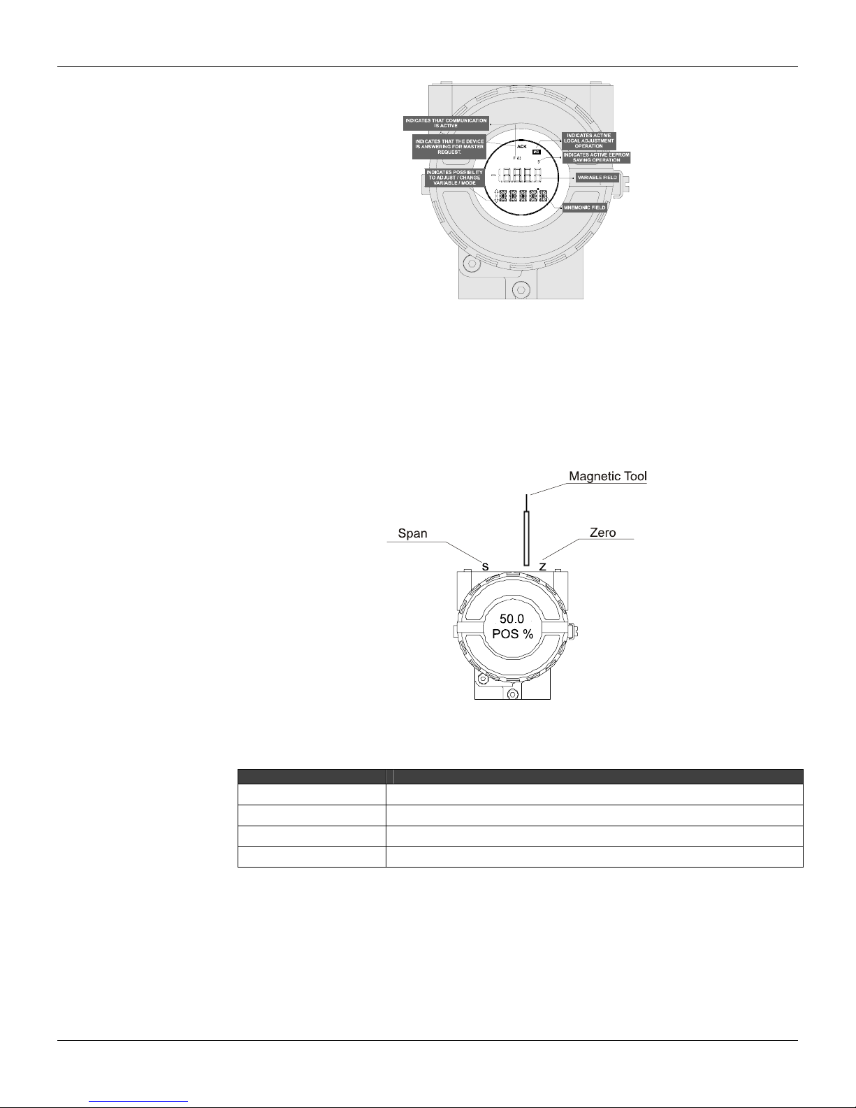
When the user chooses a variable, the display shows the parameter mnemonic, its value and status
when it is different from “good”. The field and status indicators are explained in Figure 2.1.
ation.
atic association of addresses for the H1 network device,
guration, operation and diagnosis can be
2.1
Page 28
Series 302 FIELDBUS FOUNDATION – Installation, Operation and Maintenance Manual
Indication Operation
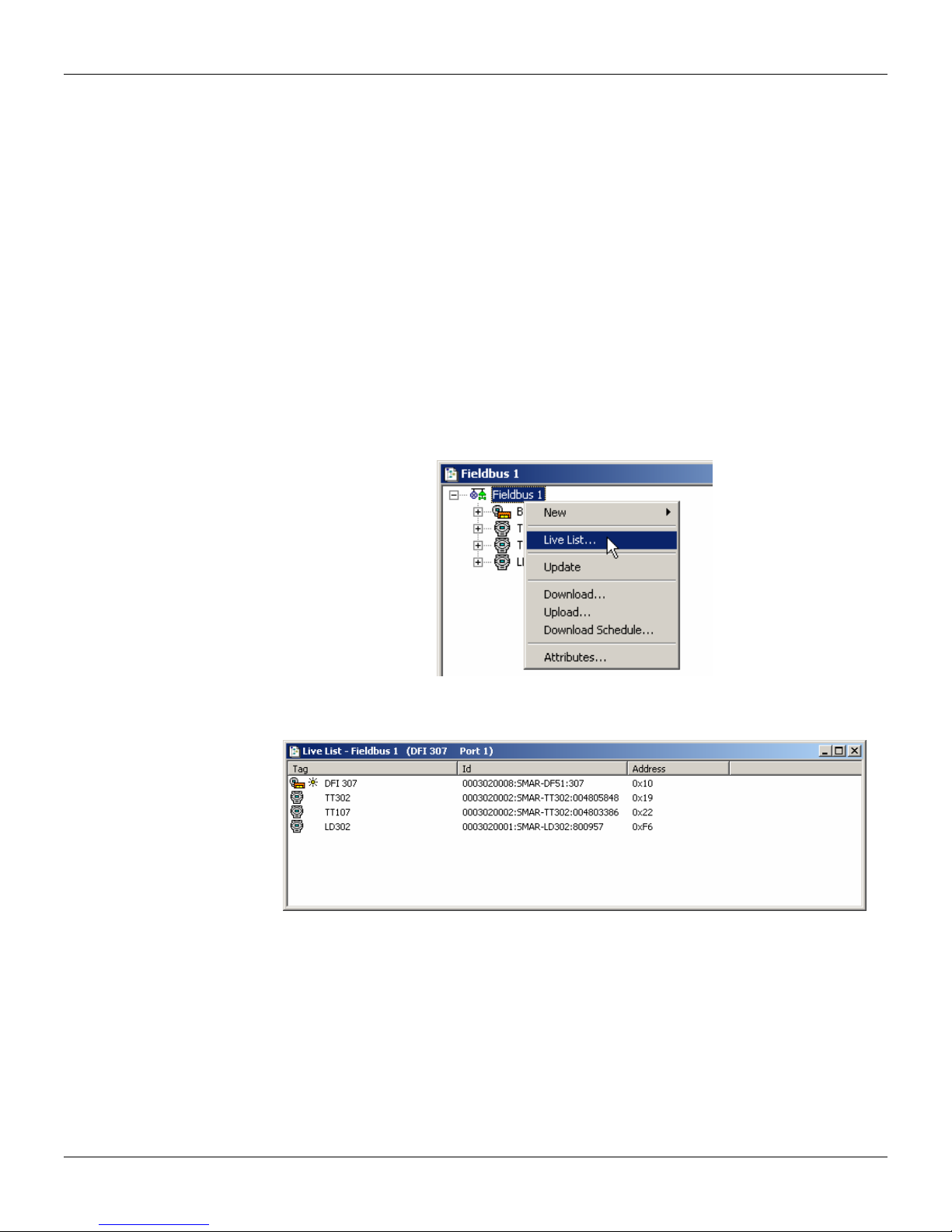
During the indication operation, the Series 302 equipm
mode, it shows a variable indicated by the user configuration. Figure 2.2 shows the indicator
displaying a “position”. Whenever the displayed value exceeds "19999, it will appear with a two-digit
mantissa and an exponent.
The indication mode is interrupted when the user performs an action with the local adjustment.
Figure 2.2 - Typical Normal Display Showing PV, in this case 50.0 %
The display is also displays errors and other messages. See Table 2.1 – Displayed Messages.
Display Description
INIT
BOUT
FAIL
FACT
Basic details of the Syscon Use
Introduction
Syscon is the software tool that configures, maintains and operates the newest SMAR product line
and communicates with the comprehensive new series of controllers. These controllers are all
connected to the High Speed Ethernet providing field network connections to well-known
F
OUNDATION fieldbus
2.2
Figure 2.1 - Indicator
ent stays in the monitoring mode. In this
The device is in initializing mode after power on.
The sensor is open or not connected properly (when it is applicable).
The device presents some fail or malfunctioning
The device is recovering default configuration to non-volatile memory.
Table 2.1 – Displayed Messages
TM
protocol. For more details, please, consult the Syscon Manual.
Page 29
Operation
Communication
The friendly Man-Machine Interface (MMI) provides an efficient and productive interaction with the
user, without previous knowledge of the software. A large library of pre-configured and tested
templates for devices, control strategies and graphic symbols makes the engineering system as
efficient and as fast as it can be. Only a minimum of data needs to be entered when defining I/Os,
networking, and control strategies.
Support Tool
The plant control configuration is now managed by a unique tool, the Studio30 2, which integrates all
applications included in the Smar’s SYSTEM302 Enterprise Automation System and incorporates
Windows-based Users and Groups to provide a multi-user environment. Now the Syscon project
files have controlled access defined for each professional operating the p lant and a precise register
of the history of modifications to guarantee the integrity of the project configuration data.
Live List
The Live List function is available in the support too ls and provides a list of all equipment in the
fieldbus network after communication startup.
On the Fieldbus window, select the fieldbus icon, search
click on the fieldbus icon with the right button to open the menu an d select the L ive List item. Figur e
2.3.
the View menu and click on Live List or
Figure 2.3 - Live List
The Live List window appears, as shown in Figure 2.4.
Figure 2.4 - Live List Window
The Live List window shows the devices and bridges identified by the d evice tag, ID and address,
and also the device configured as Active LAS (Link Active Schedule). The active LAS is indicated b y
a different icon on the Live List.
Table 2.1 below describes the icons that identify the
Live List.
instruments and bridges in the window of the
2.3
Page 30
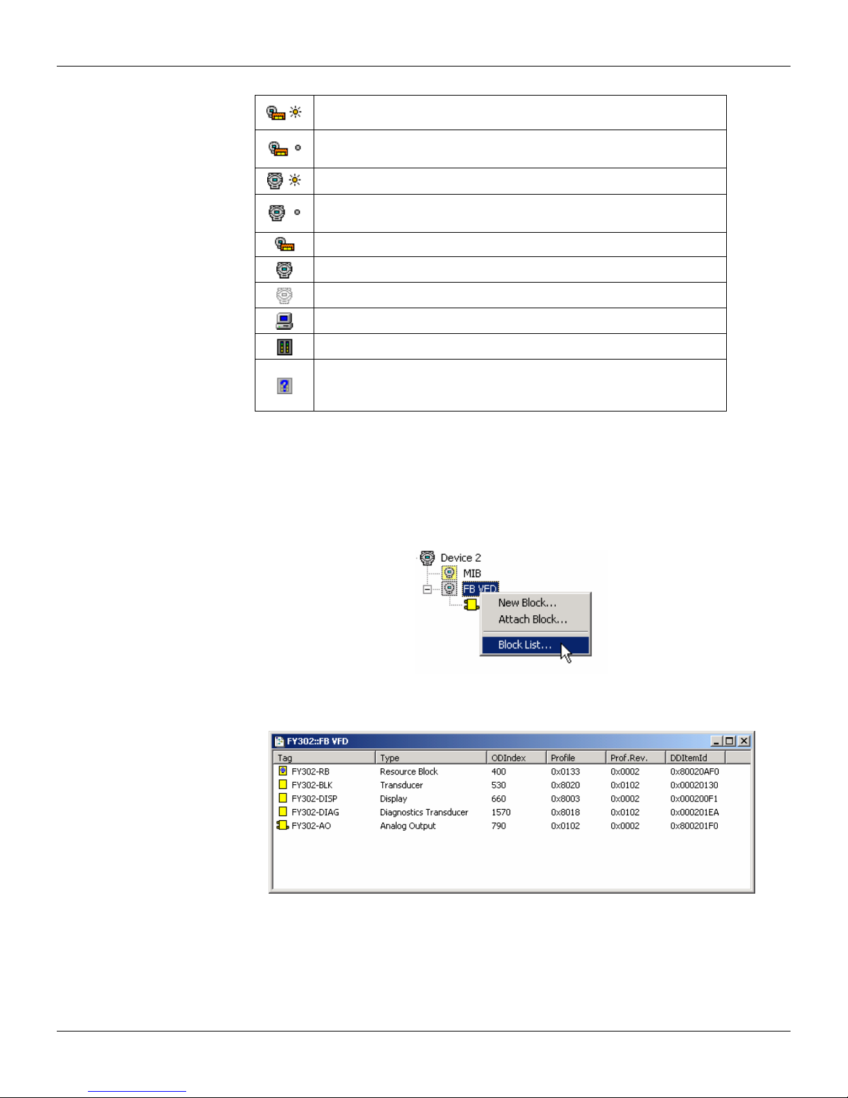
Series 302 FIELDBUS FOUNDATION – Installation, Operation and Maintenance Manual
Active LAS Bridge.
Bridge set to assume the LAS function when the active LAS stop
communicating.
Active LAS field device.
Field device set to assume the LAS function when the active LAS stop
communic
Bridge H1 or HSE.
Field device H1 or HSE.
Information reading from the field equipment in process.
HSE Host.
Third-party gateway or I/O modules.
Bridge or field device that has no sup
blocks file (Flexible Function Block)). This situation can occur when
there is some FFB block with ladder logic in the configuration.
ating.
porting files (DD, CF or FFB
Table 2.1 - Icons that identify instruments and bridges in the Live List
Block List
The list of blocks instantiated in an instrument may b e visualized through the Block List, after the
communication was initialized.
In the Fieldbus window, select the FB VFD icon, searc
the FB VFD icon with the right button to open the menu and select the Block List item.
h the View menu on the Block List or click in
2.4
Figure 2.5 – Block List
The Block List window is displayed:
Figure 2.6 - Block List Windows
Page 31

Using the AssetView Asset Manager
The Smar AssetView is a software system for online network-enabled asset management. The
primar
y objective is to unleash the powerful diagnostics capabilities found in Fieldbus devices in
general and in Smar devices particularly, providing several maintenances schemes and a userfriendlier interface
AssetView deals only with devices and is used for the long-term maint enance and device operation.
AssetVie
through test sequences, recorded data and plot c harts providing a much more soph isticated failure
analysis.
Another important characteristic of the Asse
user interface is the Internet Explorer web browser and it can be used on any Windows platform.
For more information see AssetView Manual.
w is not restricted to just displaying device error messages, but it can analyze devices
Visualizing the Device Page
Each device has a standard Web page layout. Each d evice installed in the plant has a page where
the user can c
Navigate the topology tree and click on a device ic
page with the FY-302-AV01 tag.
alibrate, configure, detect, diagnose or reconcile the device configuration.
Operation
tView is the web-based architecture technology. The
on to view its page. Figure 2.7 shows the FY302
For each type of device, the main p
Calibration
Calibration is the correction of sensor readings an
are displayed to the user indicating the status of this condition. There are specific calibration
methods for each device based on scripts defined by the manufacturers.
Configuration
In the Configuration page, the user c
this page, the user can also access the Reconciliation page and com pare the current configurations
to previous device configurations stored in the database. Refer to subsection Reconciliation.
Figure 2.7 - Initial Page of an AssetView 4.3 Device
age can have the following links:
d physical outputs. During this process, messages
an read and write the parameter values of the devic es. From
2.5
Page 32

Series 302 FIELDBUS FOUNDATION – Installation, Operation and Maintenance Manual
Diagnostics
Simple diagnostics are displayed to the user. Comprehensive tests ca n be done from time to time
g several charts to check the condition of the field device. Because of the diagnostic it is
usin
possible to first remotely check the device if there r eally is a failure before going into the field. And
yet, because of the detailed information about the Network and d evice operation provided by the
diagnostics, the user knows exactly where the problem is.
Identification
The Identification page prov
as its manufacturer, device type, tag, serial number, and its versions. Construction materials for
wetted parts are also indicated.
ides all the information relevant to the maintenance of the d evice, such
Device View
The Device View page monitors the instrument data, suc
from the instrument.
h as temperature or pressure values read
Display
In the Display page, the user can co
such as device mnemonics.
nfigure the device’s display, viewing and modifying parameter s
Reconciliation
Reconciliation allows comparison of current device s
database. The Time menu on the left side of the page lists the modifications made in the device,
including the last modification that is also called the “current device pa rameterization”. The Time
menu on the right side also lists the modifications made in the device, except date and time for the
current device parameterization.
ettings with past configurations stored in the
2.6
Figure 2.8 - Device Reconciliation Page (Instrument)
Page 33
Section 3
LOCAL ADJUSTMENT SETTING
To configure the function blocks and communication in the Series 302 equipment use the
uration system called Host. The heavier and difficult task is automated and the ri sk of
config
configuration error is reduced. In the case of the Smar SYSTEM302 (Smar), an automatic
guide directs the user to commission the device properly. In this system, the equipment
addressing is made with the same physical tag.
The steps described below are based on the Smar – S yscon system configurator 6.1 Version.
Importantly, these settings may vary with each manufacturer.
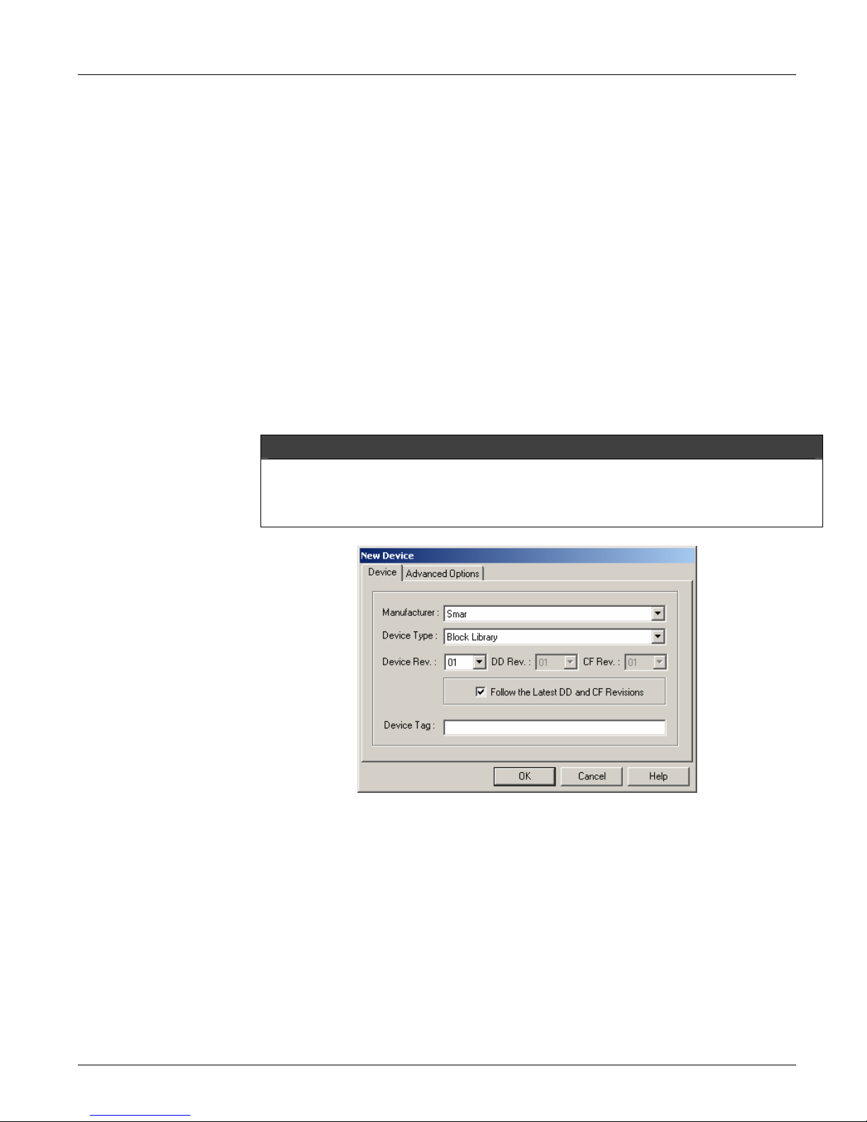
Creating Devices
On the Fi
Device dialog box will open.
Select the Dev
manufacturer.
Select the De
option Follow the Latest DD/CF Revision to apply the latest revision for the selected device.
If the option Follow the Latest DD/CF Revision is selected, Syscon will update the device with
the latest revision of the DD and CF every time the configuration file is opened. T o disable the
automatic update, right-click the device icon, click Exchange and unmark that option on the
Exchange dialog box.
eldbus window, right-click the fieldbus icon and click New > Device. The New
ice Manufacturer from the list and the Device Type provided by the selected
vice Revision, then select the DD Revision and the CF Revision, or check the
NOTE
Type a related tag for the device. If you do not define t he tag, De
where n is a sequential number for devices.
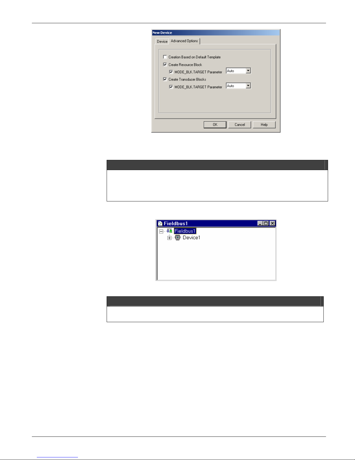
At the Advanc
and parameters, according to the Capabilities File:
Creation Based on Default Template: cre
file for the selected Device Revision, located in the corresponding Device Support folder.
Create Resource Block:
device. You can set the initial value for the Mode Block parameter.
Create Transducer Blocks:
device. You can set the initial value for the Mode Block parameter.
Figure 3.1 - Device Dialog Box
vice n will be the default tag,
ed Options tab, select the options to automatically create and configure blocks
ates the device based on the Default Template
automatically creates the Resource Block of the selected
automatically creates the Transducer Blocks of the selected
3.1
Page 34
Series 302 FIELDBUS FOUNDATION – Installation, Operation and Maintenance Manual
t
Figure 3.2 - Advanced Options
Click Ok to ad
If the Default Template file is not found, Syscon will automatically create the Resource and
Transducer Blocks for the selected device.
If the tag is not entered, Device n
he instruments.
The Fieldbus window will be similar to the Figure 3.3 bellow:
d the device to the configuration.
OBSERVATION
will be the default tag, where n is a sequential number for
3.2
Figure 3.3 – Fieldbus Window
IMPORTANT
The HSE Device can only be added to the HSE Fieldbus. Likewise, the H1 Device can only
be added to the H1 Fieldbus.
Creating a Device from a Template
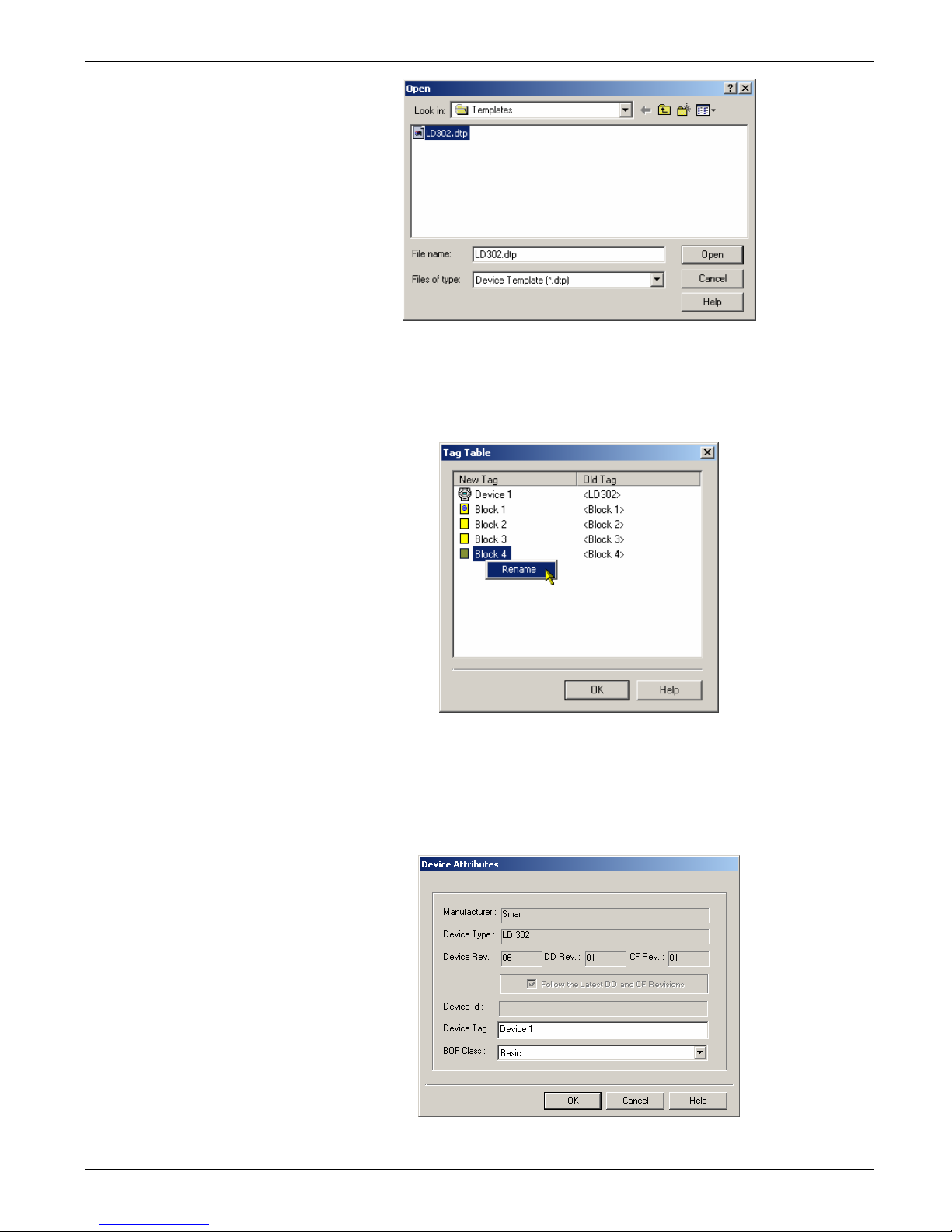
Para criar um instrumento baseado em um arquivo model o, selecione o ícone do fieldbus , vá
enu Edit e clique em Import Device Template. Também é possível criar um instrumento
ao m
através do menu do fieldbus, clicando sobre o ícone com o botão direito e selec ionando o
item New > Device from Template.
On the F
Select the directory where the template file is located, select the device template file and click
Open. A message b
ieldbus window, right-click the fieldbus icon and click New > Device from Template.
ox will open to confirm the operation. Click Ok to proceed.
Page 35
Configuration
Figure 3.4 - Selecting a Model Instrument
g Table will open, showing the list with block and device tags based on the preferences
The Ta
settings and the old tags used in the template file. To edit a tag, right-click the block or devic e
icon at the New Tag column and click Rename. Type the new tag and click Enter on the
keyboard.
Figure 3.5 - Tag Table Dialog Box
Click Ok to close the
Tag Table dialog box and add the device to the configuration.
Changing the Device Attributes
Right-click the device icon and click Attributes. The Device Attributes dialog box will open.
Figure 3.6 - Device Att
ributes Dialog Box
3.3
Page 36
Series 302 FIELDBUS FOUNDATION – Installation, Operation and Maintenance Manual
W
NOTE
hen the Syscon is in on-line mode, the De vice Selection dialog box displays the devices that
have not been instantiated in the project.
If the user selects Unspecified in the Device Tag list and apply this tag to the instrument, the
Syscon will automatically generate a new tag for the standard instrument, based on the
preferences settings.
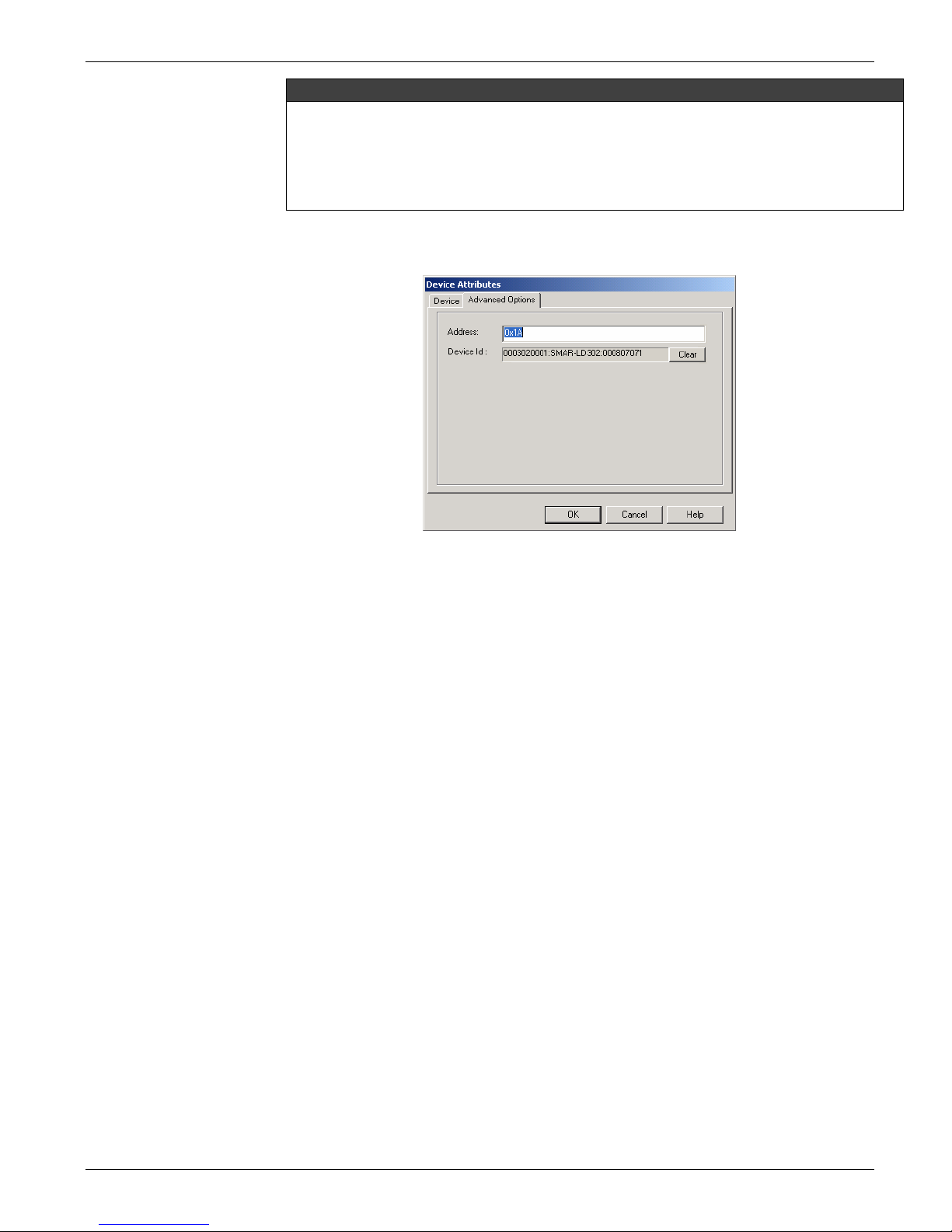
When operating in the A
the Device Attributes dialog box. Type the new physical address for the device.
dvanced User mode, the tab Advanced Options will be available in
Figure 3.7 - Advanced Options
Enter the physical address in the Address field of the instrument.
The normal commissioning operation should use the options Commis
Decommission. Only for some engineering and test scenarios, with the Syscon in Advanced
Mode options, it is possible to delete the Device Id from the instrument without using the
decommissioning procedure.
Click Cle
it only disassociates the physical device from the instrument on the configuration.
Click Ok to ap
ar to delete the Device Id. This procedure do not replace the Decommission o ption,
ply the alterations and conclude.
sion and
Master Backup Device
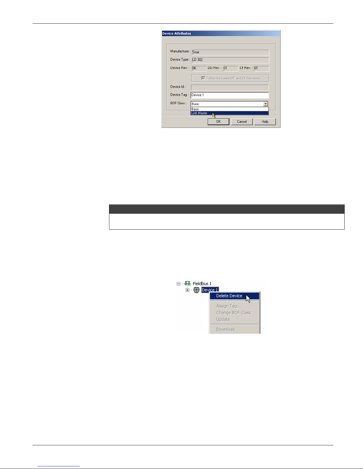
To configure the device to operate as a Master Backup, a L
Right-click the device icon and click A
and select the Link Master option.
Click Ok to conclude.
ttributes. Click the down arrow on the BOF Class box
ink Master should be selected.
3.4
Page 37
Configuration
Figure 3.8 - Configuring the Link Master Device
When the Syscon is working online, open
Click Yes to confirm the change and Syscon will display a message requesting that the
instrument is rebooted.
A message box will inform that it is necessary to rein
execute the Download Schedule in the channel where the device is configured: right-click the
fieldbus icon and select Download Schedule.
After the download, the device will operate as a Link Master
During the download, all Master Backups in the Fieldbus Network will be configured with the
Traffic Schedule.
the device menu and select Change Class BOF.
itialize the device. Reset the device and
.
OBSERVATION
Deleting Devices
To remove a device from the Fieldbus window, right-click its icon and click Delete, or press
Delete on your keyboard.
The warning dialog box will appear. Click Yes to confirm the oper
ation.
Figure 3.9 - Deleting Devices
Figure 3.10 - Confirming Operation
3.5
Page 38
Series 302 FIELDBUS FOUNDATION – Installation, Operation and Maintenance Manual
Ordering Devices
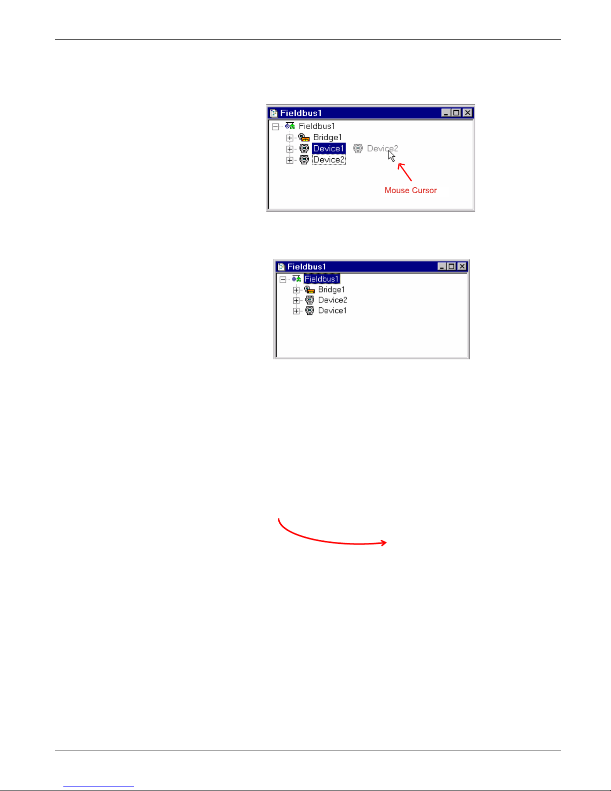
Select a device icon and drag it over the other d
above the other device in the configuration tree.
Figure 3.11 - Fixing the window Fieldbus Instruments
The window Fie
ldbus will be as in the Figure 3.12:
evice icon. The selected device will be placed
3.6
Figure 3.12 – Fieldbus Window
Moving Devices
To move a device from one fieldbus to another, click to select the device icon in the Fieldbus
window and drag the device over the other Fieldbus win d ow.
If there are any block links connecting the device to its original F
ieldbus window, these links
may no longer be available for the communication, because no valid path would be found in
the topology. The incomplete links will be identified by a dotted line in the Strategy windo w.
Figure 3.13 - Moving a Device
Device Exchange
When a defective device must be replaced by a new device with a ne wer or different Device
Revision, it
configuration. You can also use the Exchange procedure to change the Device Revision.
The Device Exchange checks the inconsistencies, incompatibilities and interchangeability
problems, and generates a report about the changes that will affect the configuration.
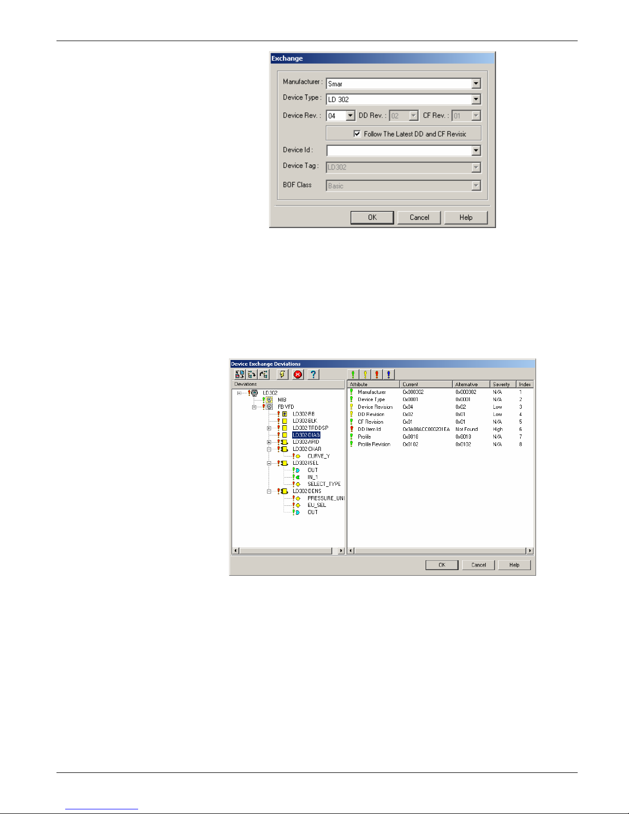
To exchange a device, right-click its icon and click Exch
open:
is possible to exchange these devices easily without modifying the existing
ange. The Exchange dialog box will
Page 39
Configuration
Figure 3.14 - Device Exchange Dialog Box
You can change the Manufacturer, the Device Type and the Device Revision attributes. Edit
the attributes and click Ok.
Syscon
will compare the new device capabilities with the previous device capabilities and
display the incompatibilities at the Device Exchange Deviations dialog box.
The De
viations dialog box shows detailed information about the device, blocks and
parameters, indicating to the user the functionalities that can be lost when exchanging the
device. See the example below:
The panel on the left shows the blocks and parameters configured in the original device and
indicates the new device compatibilities.
The panel on the right compares the original dev ic
Click the column headers (Attribute, Current, Alternative, Severity or Index) to sort the list of
parameters. Clicking the column header will also toggle between ascendant and descendent
sorting.
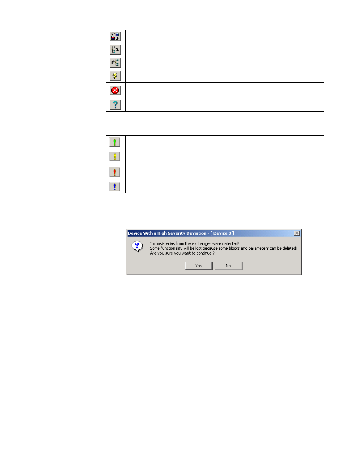
The Deviations dialog box has its own toolbar. The following table describes the
functionalities of the buttons:
Figure 3.15 - Device Deviatio
e attributes to the new equipment selected.
ns Dialog Box
3.7
Page 40
Series 302 FIELDBUS FOUNDATION – Installation, Operation and Maintenance Manual
Click this button to refresh the informatio
Click this button to expand all nodes.
Click this button to collapse all nodes.
n on the dialog box.
Click this button to accept the changes and close the De
Click this button to cancel the Exch
dialog box.
Click this button to open the Syscon Online Help.
ange procedure and close the Deviations
viations dialog box.
The Dev
iations dialog box has four filter levels that classify all of the blocks and parameters
attributes for the device:
The attributes classified by this filter are com
pliant with the device.
The Low Severity filter indicates that the attributes are not compliant but the
information won't be lost.
The High Severity filter indicates that the attributes are not compliant and the
information can be lost or converted.
This filter will display all attributes.
Click Ok to confirm the Exchange procedure. Syscon will verify the compatibility of the
blocks. If a block is not available in the target device, a dialog box will open alerting the user
that inconsistencies were detected and some functionalities will be lost if the device is
exchanged.
3.8
Figure 3.16 - Detecting Inconsistencies
Click Yes to co
nfirm the exchange or click No to cancel the procedure and discard the device
alterations.
If you confirm the Exch
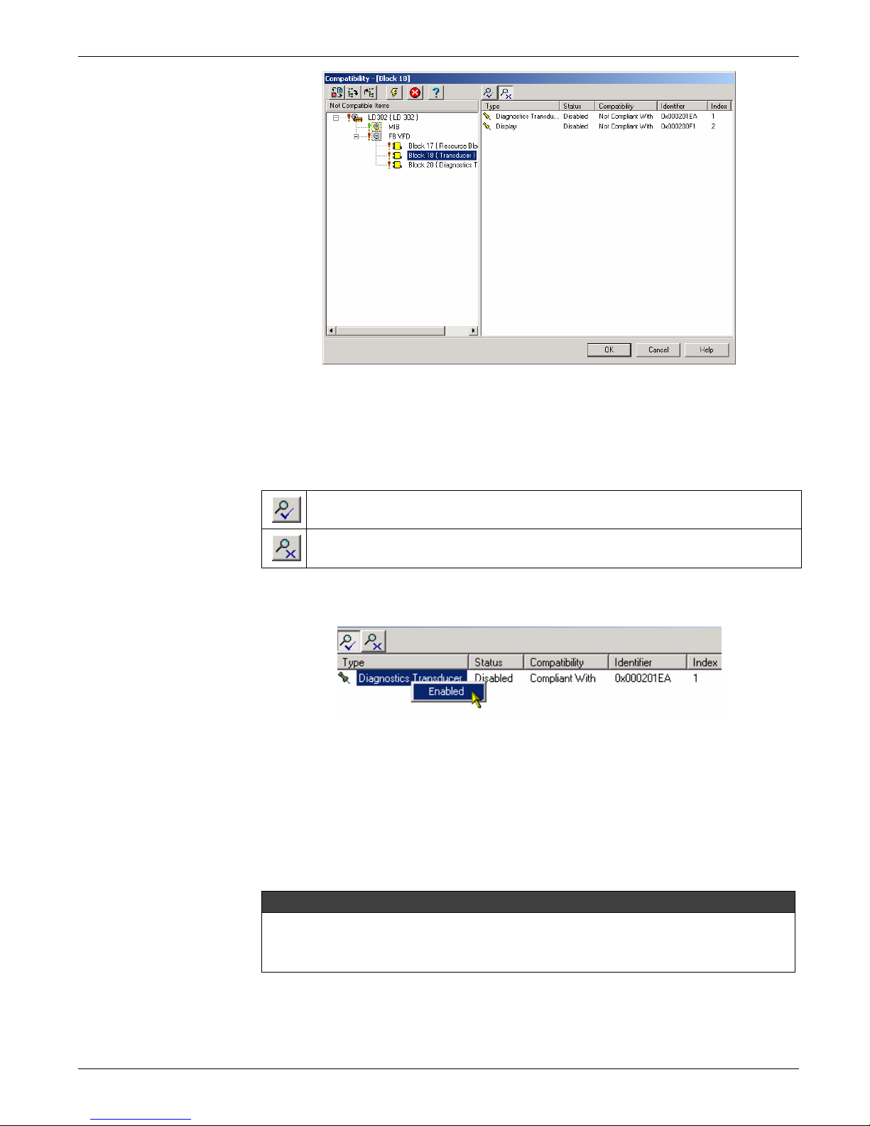
ange procedure, the Compatibility dialog box will open. The
Compatibility dialog box allows you to replace the blocks from the previous device that are
not compatible with the new device. See the example below:
Page 41
Configuration
Figure 3.17 - Compatibility Dialog Box
The panel on the left indicates the blocks that are not compatible with the new device. For
each block not compatible, click its icon and the panel on the right will show the types of the
compatible blocks.
Use the buttons in the toolbar to filter the blocks:
This filter shows the list of blocks from the new device, which is compatible to the
blocks from the previous device.
This filter shows the list of blocks from the new device, which is not compati
the blocks from the previous device.
Right-click the icon of the compatible block and click Enable to replace the old block in the
device.
ble to
Repeat this procedure for each block that is not compatible with the new device. Click Ok to
confirm the alt
Blocks that cannot be converted will be removed from the confi
Recycle Bin. Parameters cannot be converted. If there is no identical parameter in the new
device, the parameter will be deleted and will not be sent to the Recycle Bin.
For more details see Configurator Software Manual.
The local adjustment can be used for basic operations and some configuration tasks. This
eliminates the need for a high performance configurator system, but requires more
knowledge. See the section Local Adjustment Methodology how to use the local
adjustment.
Function Blocks
For function block configuration details see the Function Blocks Instruction Manual.
Figure 3.18 - Selecting a Compliant Block
erations and close the Compatibility dialog box.
guration and sent to the
NOTE
3.9
Page 42
Series 302 FIELDBUS FOUNDATION – Installation, Operation and Maintenance Manual
Display Transducer
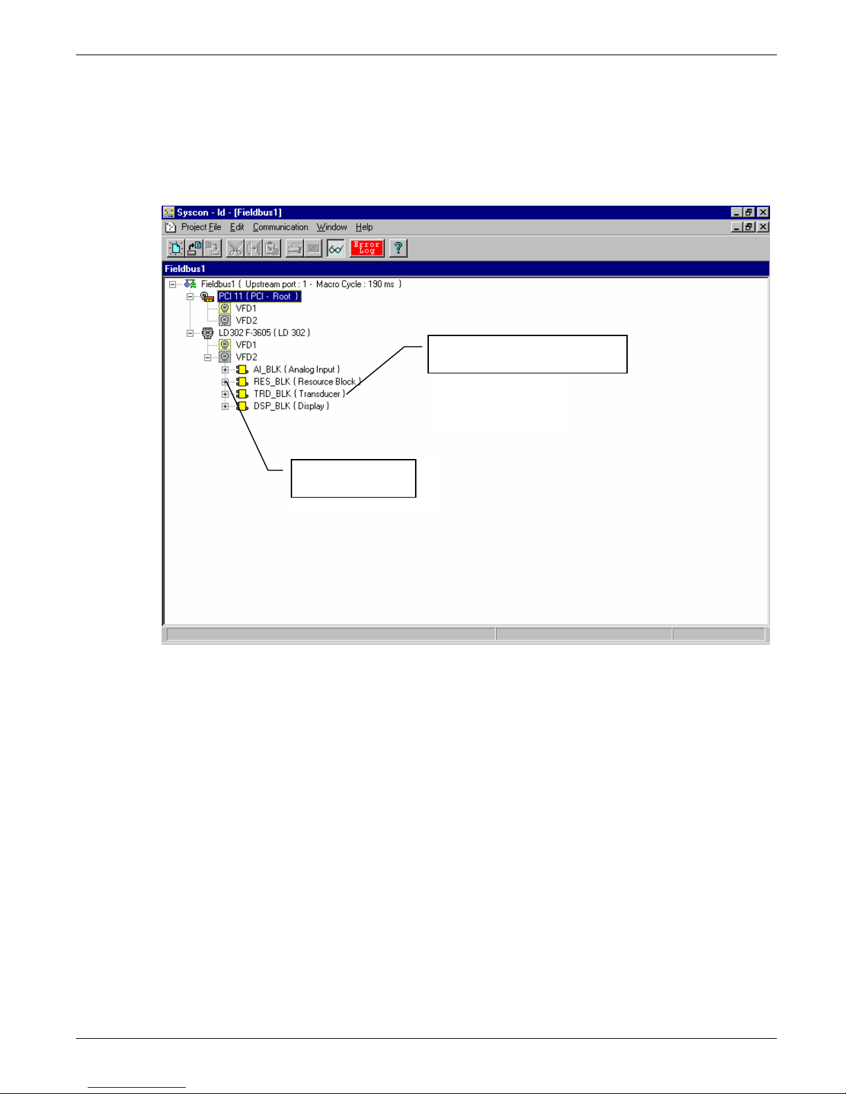
The 302 series devices can be equipp ed with an LCD displ ay. In the normal monitor ing mode,
ystem may show a variable.
the s
The display transducer block can be configured b
LD302 has four blocks instantiated: analog input block, d isplay and Tr ansducer and Resource
blocks.
The transducer and the display are
handled as special function blocks.
y the Syscon. In the example below, the
Instantiated blocks
blocks
Figure 3.19 – Function Blocks and Transducers
3.10
Page 43
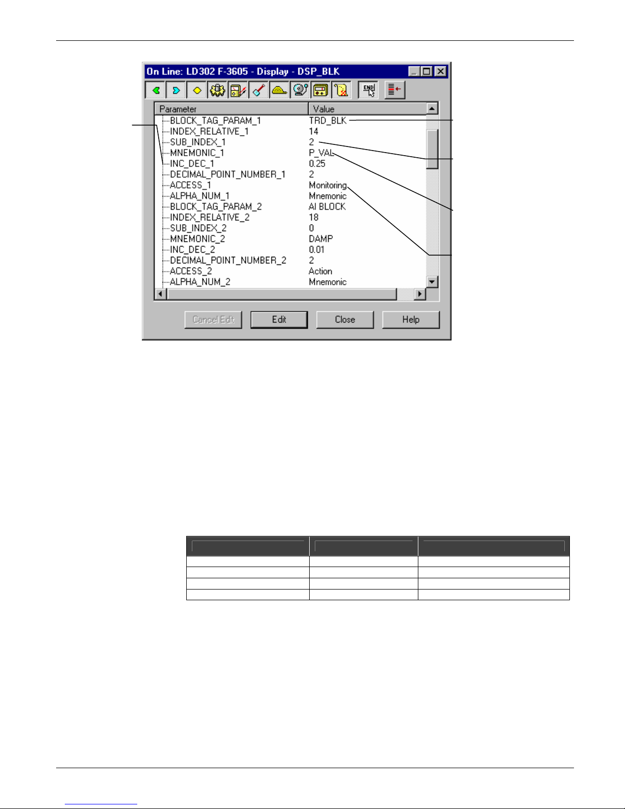
A group of
paramete
be set to show
and/or act on a
given parameter in
the local
adjustment.
rs must
Configuration
Specifies the block
tag where the
desired parameter is
parameter.
Relative index to
selected
parameter
This mnemonic
characterizes the
parameter that appears
on the display
Type of access:
monitoring and
acting upon the
parameter
The display block is handled as a common function block. This means that this block can be
configured by Syscon, setting parameters and choosing values according to the user's needs.
The LCD display can be used for parameter monitoring or performance
Local Programming Tree
The programming tree is a menu system that allo w
items. The menu is configured through the display block.
Each field device is supplied with a factory default setting.
There is a default setting for each type of field eq
output or input of the transducer block as a monitoring par ameter and calibration parameters
as shown on Table 3.1:
Parameter Function Class
Primary Value Monitoring Read
Figure 3.20 – Display of the Transducer – Configuration
s the configuration of the most important
uipment, but usually it includes the tag, the
Tag Monitoring Read
Lower Calibration Read/Write
Upper Calibration Read/Write
Table 3.1 - Configuration Indicator Example
3.11
Page 44
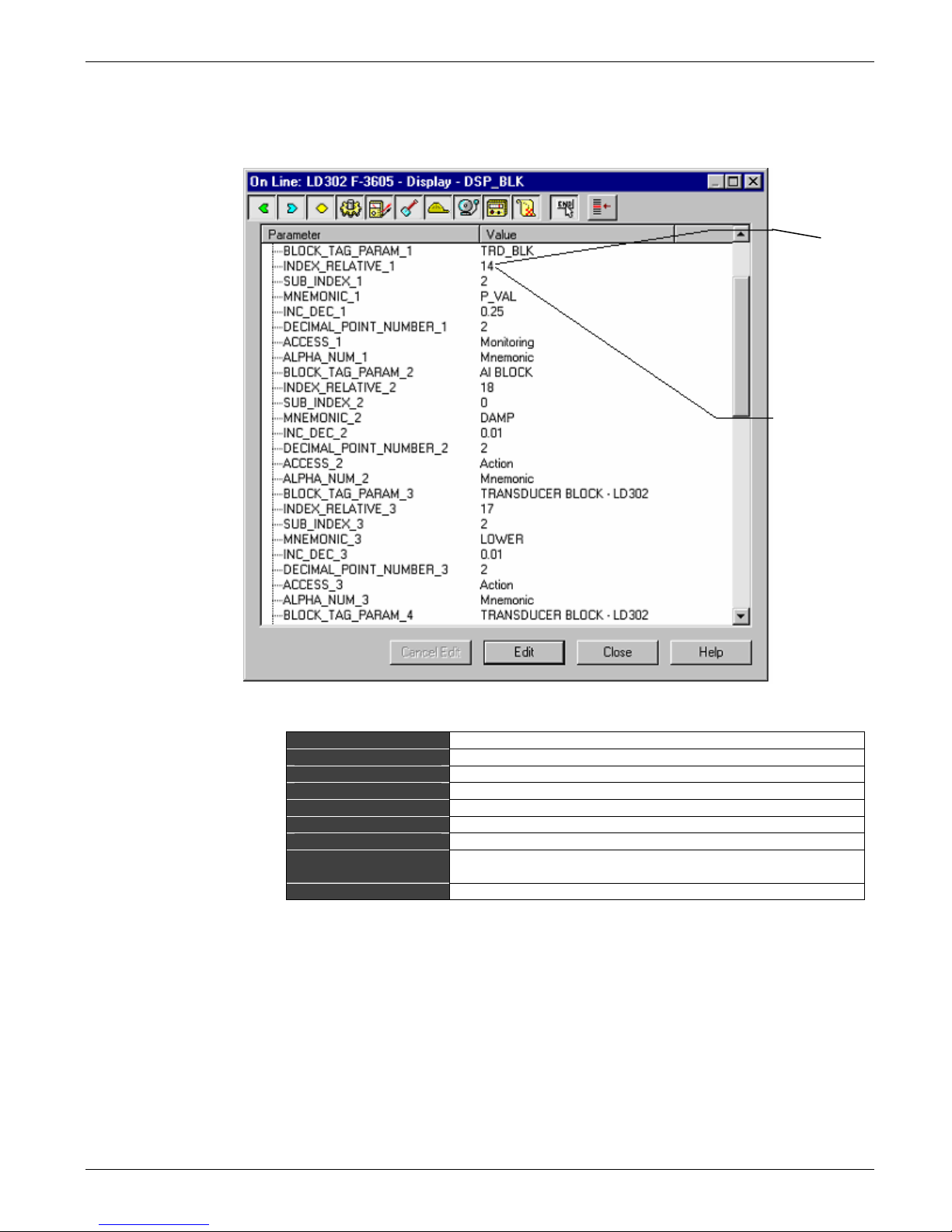
Series 302 FIELDBUS FOUNDATION – Installation, Operation and Maintenance Manual
Display Configuration Using Syscon
The user must determine and set up the values descri
parameter.
Figure 3.21 – Display Block Parameter Adjustments
Block Tag
Relative Index
Sub-Index
Mnemonic
Float Inc_Dec
Decimal Point
Acces
Alpha_Num
Refresh
Tag assigned to the function block.
Relative index of the specified block parameter.
Logical member sub-index.
Mnemonic assigned to the parameter.
Step to increase or decrease for a float or integer type.
Number of decimal places after the mantissa.
Permission to Read and/or Write.
Select the mnemonic or value in the display when the value is
greater tha
n 10,000.
Flag to indicate new configuration.
Table 3.2 – Display Block Parameters
Local Adjustment can be fully configured by Syscon. The user can set the parameters to be
adjusted or monitored locally. Usually, these parameters are inputs and outputs of control
function blocks. It can also change the parameter mode and tuning.
Almost all function block parameters configured by Syscon, can be adjusted locally.
The user can select them using the following data types:
• Integer
• F
loat
• Status + Float
• Mode
•
Tag (read – only)
bed in the table below, for each selected
This value indicates
that a default
parameter index 14
and the sub-index 2
of the transducer
block – LD302 are
set as monitoring
Index 14 represents
the LD302 transducer
block output. It is a DS64 type (DS-64)
variable, i.e., status –
float value. The subindex indicates the
item’s data structure,
for example, 1 selected
the status and 2
selected the value.
When the parameter is
sample, i.e., not a data
structure, there is no
need to configure the
sub-index.
3.12
Page 45
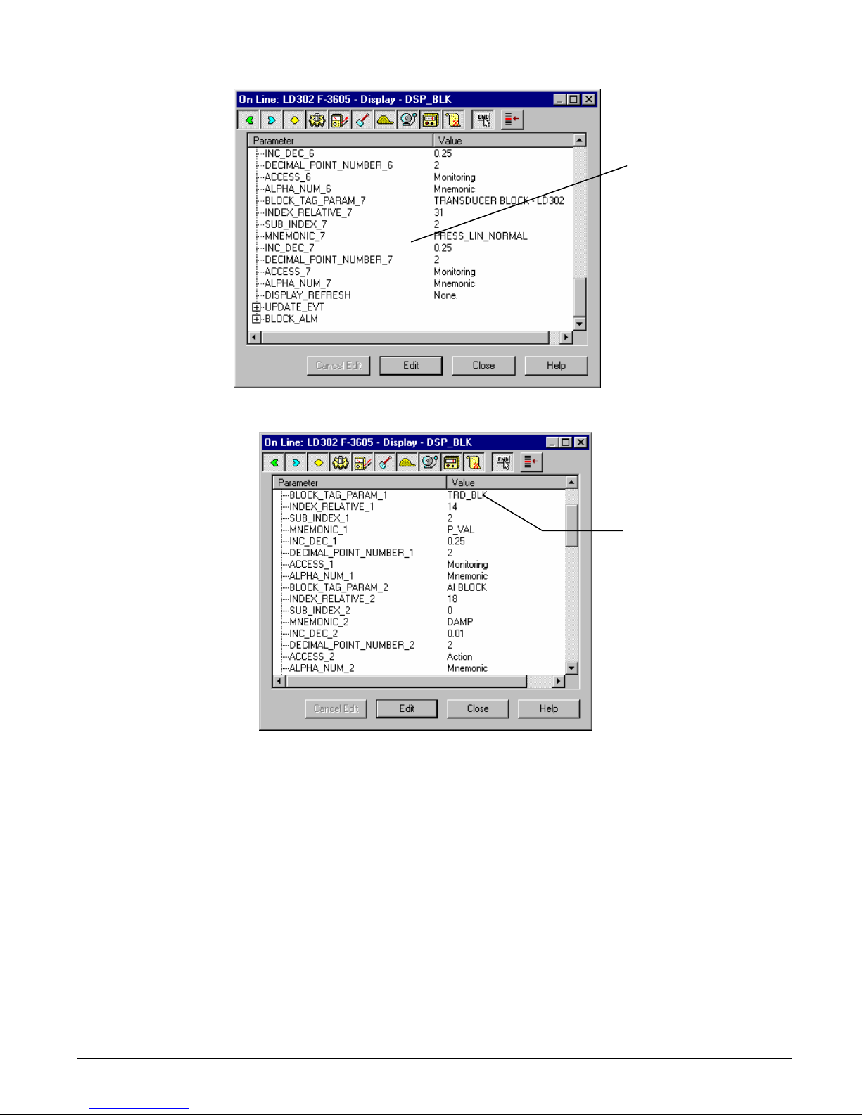
Configuration
These settings are
required to set a
parameter on the
LCD display.
Figure 3.22 – Display Block Parameter Adjustment
After the first firmware
download, the display
block will adjust the
tags of functional
blocks with default
values.
Figure 3.23 – Display Block Parameter Adjustment
3.13
Page 46
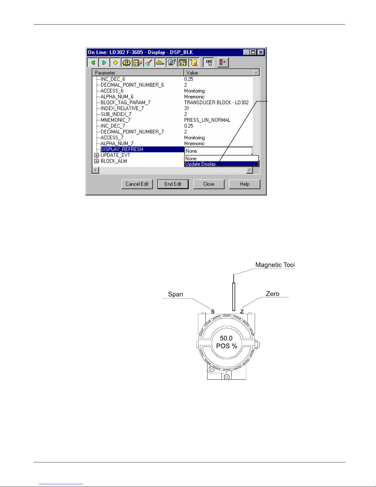
Series 302 FIELDBUS FOUNDATION – Installation, Operation and Maintenance Manual
Figure 3.24 – Display Block Parameter Adjustment
Using Local Adjustment
To enable this function, the equipment must
The equipment has two holes located under the identification tag, and the magnetic sensors
are activated via magnetic tool. See Figure 3.25.
have the digital display.
To validate and update
the new of the display
block configuration select
"Update Display”
The magnetic tool enables adjustment and monitori
local adjustment tree.
The "LOC.
3.14
Figure 3.25 – Local Adjustment
ng of the parameters configured on the
ADJ" at the top of the main board must be in position ON.
Page 47

Local Adjustment Methodology
Enter the local adjustment by inserting the magnetic tool in the ZERO hole. Wait until the
"MD" flag appears on the LCD. Then insert the magnetic tool t wice in the SPAN hole The
message "LOC ADJ" will appear. Next, insert the magnetic tool in the ZERO hole. L eaving
the tool in the ZERO hole, browse through the items in the menu. The ZERO hole is used for
browsing. By moving the tool to the SPAN hole, the parameter can be set on another value.
SUMMARY:
Zero (z) Browses
Span (s) Selects / Actions.
To browse the available parameter options, move the tool to the ZERO hole to go to the
specific menu option. See Figure 3.12. Then make a selection by moving the tool to SPAN
when the choice is displayed. If the options are on/off, or enumerated, the option will appear in
the value field. The mnemonic of each parameter will be displaye d on the alphanumeric field.
This is for viewing only, as changes are not to be m ade on the tag configured for the bl ock. If
the Functional Block tag is longer than five characters, it will move to the left.
If the magnetic tool is kept in the SP
is numeric. By temporarily removing the tool from the SPAN hole and then reinserting it, the
working speed is reduced.
When the user inserts in and removes the magnetic tool fro m the SP
decrement will be done in steps.
Remove the tool when the desired value is reached.
When incrementing a variable beyond the value desire d, move the tool to ZERO and
the decrement option of the same variable appears. By moving the tool to SPAN, it is reduce d
to the desired value. For "undershoot", the opposite applies.
To exit from any menu, remove the tool from any hole fo r a break, and an escape sequence
w
ill return to normal display.
The arrows inside each mnemonic indicate that the user ca
parameter has reading and writing access.
Whenever the user decrements the val
this value” when the magnetic tool is inserted into the ZERO hole.
Then the user enters the local adjustment, the last parameter used before is shown.
To monitor a parameter in normal operation, the user just needs to browse at the desired
parameter and remove the magnetic tool. Then this parameter will be sho wn continuously on
the LCD.
Every action should be done critically because no confirmation is required to change the
parameter value. After writing the value, it is automatically stored in the E2PROM memory.
Almost all Function block parameters can be conf igur
select them from the following classes:
• Integer
•
Float
•
Status + Float
• Mode
•
Tag (read-only)
All of them can be set or monitored b
Configuration
NOTE
AN hole, the action will be continuous when the parameter
AN hole, the increment or
wait until
n change the value by writing if the
ue of a parameter, he is given an option to “increment
NOTE
ed by local adjustment. The user should
y using the magnetic tool.
3.15
Page 48

Series 302 FIELDBUS FOUNDATION – Installation, Operation and Maintenance Manual
The default values for the local adjustment are trim parameters, transducer block out put or
input and Tag identifying the block.
How to Configure a Transducer Block
Each time you select a field device on the config
transducer block as it appears on screen.
The transducer block has an algorithm, a set of contained parameters and a channel
ecting it to a function block.
conn
The algorithm describes the behavior of the transd
I/O hardware and other function block. There are several parameters in the Function Block.
They can be divided into Standard and Manufacturer Specific.
The standard parameters are available for such class of inst ruments as pressure, temper ature
actuator devices, etc., whatever the manufacturer. Oppositely, the manufacturer specific ones
are defined only by their manufacturer. Common manufacturer specific parameters are
calibration settings, materials information, linearization curve, etc.
When you perform a standard routine as a calibr
method. The method is generally defined as guideline to help the user to make common tasks.
The configuration tool, for example the Simatic PDM, identifies each metho d associated to the
parameters and enables the interface to it.
uration tool, automatically you can see the
ucer as a data transfer function between the
ation, you are guided step by step by a
Channels
Identifies the channel interface between the transducer blo ck and the function block according
to the manufac
turer. This number starts from the value 1.
Calibration
This is a specific method to make the calibration operation. It is necessar
of reference applied to or connected to the device with the required value. Some p arameters
should be used to configure this process: CAL_POINT_HI, CAL_POINT_LO, CAL_MIN_SPAN
e CAL_UNIT. Those parameters define the highest and lowest calibrated values for each
device, the minimum allowable span value for calibration (if necessary) and the engine ering
unit selected for calibration purposes, when differentiated by SENSOR_RANGE or
FINAL_VALUE_RANGE.
y to match the source
3.16
Page 49

Section 4
General
NO COMMUNICATION
MAINTENANCE
SMAR Se
Nevertheless, during their design and development, consideration was given to the possibility of
repairs being made by the end user, if necessary.
In general, it is recommended that end users do not tr
boards may be ordered from SMAR whenever necessary. Refer to the item "Returning Materials" at
the end of this Section.
TROUBLESHOOTING
Basic Troubleshooting: The communication errors are detected automatically and indicated
depending on the engineering tools. Troublesho oting is a useful way to remove the parts, one by
one, until the failure is detected by elimination. It is also recommended to test the fault y device in
your own work bench. Check the following parameters:
•
•
• If the network is secure;
•
If there is not any communication, there is a problem with your configuration or installation.
Advanced Troubleshooting: In ord
the communication messages;
An oscilloscope (balanced/isolated - for example, operate
severe cases.
SYMPTOM PROBABLE SOURCE OF PROBLEM
ries 302 devices are extensively tested and inspected before delivery t o the end user.
y to repair printed circuit boards. Spare circuit
If the polarity is correct;
If the addresssis correct;
If the power supply voltage is adequate, always with a minimum 9V current during the
communication, plus the course of the Manchester sign.
er to find serious problems, bus analyzers can be used to stud y
d by battery) can also be a useful tool in
TROUBLESHOOTING
Device Connections
• Check wiring polarity and continuity;
• Check for shorts or ground loops;
• Check if the power supply connector is connected;
• Check if the shield is not used as a conductor. It should be grounded at only
one end;
• Check the coupler/link connections.
Power Supply
• Check power supply output. The voltage must be between 9 - 32 VDC at the Series 303
device terminals.
Network Connection
• Check that the topology is correct and all devices are connected in parallel;
• Check that two bus terminators are OK and correctly positioned;
• Check that the bus terminators are according to the specifications;
• Check length of trunk and spurs;
• Check the connections of the coupler are correct and correctly positioned;
• Check the baud r
• Check low isolation.
Network Configuration
• Make sure the Device Tag is configured if system configuration is desired;
• Make sure that device address, master connection, and the address.
Electronic Circuit Failure
• Check the main board for defect by replacing it with a spare one.
Table 4.1 - Diagnostic of the Field Devices
ate;
4.1
Page 50

Series 302 FIELDBUS FOUNDATION – Installation, Operation and Maintenance Manual
COMMUNICATION ERRORS
Installation problems, non-configuration or other main causes of communication err ors:
•
Loose connections
• Badly i nstalled terminator, without endpoint.
• Very low or unstable power supply;
•
Very long spurs or excessive spurs;
• Wrong gro unding or no grounding;
•
Water leak due to poor electric connections and cable clamp.
Factory Init
The Factory Init should be tried as a last optio
equipment presents some problem related to the function blocks or the communication. This
operation must only be carried out by authorized technical personnel and with the process
offline, since the equipment will b e configured with standard and factory data.
This procedure resets all the configurations run on the equ ipment, after which a partial download
should be performed. With exception to the equipment physical address and the GSD identifier
number selector parameter. After doing this, all configurations must b e remade according to their
application.
Two magnetic tools should be used to this effect, on the equipment, withdra w the nut that fixes the
identification tag on the top of the housing, so that access is gained to the "S" and "Z" holes.
The operations to follow are:
1) Switch off the equipme nt, insert the magnetic tools and keep them in the holes (the magnetic
end in the holes);
2)
Power up the equipment;
3) As soon as Factor y Init is shown on t he displa y, take off the tools and wait for the "5" s ymbol on
the right upper corner of the display to unlit, thus indicating the end of the operation.
This procedure makes effective the entire factory configuration and will eliminate ev entual problems
with the function blocks or with the equipment communication.
Note that this procedure must be performed by authorized personal only and with the process
switched off, since the equipment will be configured with standard and factory data.
n to recover the equipment control when the
4.2
Page 51

Symptoms Probable Causes Recommendations
Humidity in the terminal block and/or connectors
Excessive noise or spiking in the
bus or very high signal.
Excessive transmissions or
intermittent communication.
Communication fails with some
devices.
Intermittent powering of some or
all the equipments.
causing low
operation power supply and/or devices and/or
terminators etc inadequate shield grounding,
excessive log or spur, inadequate amount of
terminators or noise source near the Profibus
cabling.
Inadequate cabling or spur length; power supply
voltage in the wr
device operation; improper terminals,
inadequate shielding or grounding, the amount
of devices for spur in the network etc.
Repeated address in the bus, feeding tension
insufficient (<9.0 Vdc), position of the
terminators, cabl
besides allowed in the segment, etc.
Short circuit between the bus shielding and the
terminals, defective power suppl
equipment or improper amount of devices.
signal isolation, low isolation or bad
ong device terminal block; bad
e excess, amount of devices
y, excessive
Table 4.2 – Symptoms, Probable Causes and Useful Maintenance Reco mmendations
Returning SMAR Products and/or Materials
Should it become necessary to return the transmitter and/or configurator to SM
our office, informing the defective instrument serial number, and return it to our factory.
If it becomes necessary to return the transmitter and/or configurator to Smar, simpl y contact our
office, informing the defective instrument's serial number, and return it t o our factory. In order to
speed up analysis and solution of the problem, the defective item should be returned with the
Service Request Form properly filled with a description of t he failure observed and with as much
details as possible. Other information concerning to the instrument oper ation, such as service and
process conditions, is also helpful.
Instruments returned or to be revised outside the guarantee term should be accompanied by a
purchase order or a quote request.
Maintenance
Check every device connector and terminal block,
and make sure t
contact, if the shield cables are well ended and
grounded properly, the ripple level in the power
supply and in the bus are within acceptable values,
the terminator number and cable lengths and are
within the recommended values and also the cabling
is distant from noise sources. Check if the grounding
is adequate. If damaged devices generate noises,
disconnect one at a time and monitor the noise.
Check the cabling lengths, if the power supply
voltage of the de
there are no noise sources close to the Profibus bus.
In some situations, if damaged devices generate
noises or intermittence, disconnect one at a time and
monitor the status of the communication. Check the
communication AC signal course (750mV to
1000mV). Check the shielding and grounding
distribution. Check the number of devices in the
network and per spur.
Make sure all the devices have different addresses,
and note that
address 126, place it according to the configuration,
and only then include another device with address
126 in the bus. Check the cabling lengths and
amount of devices, as well as their power supply and
terminators positioning.
Check the shield isolation, the amount of devices
and their consum
hat no humidity got in; detect bad
vices is between 9 to 32 Vdc, if
when placing a device in the bus with
ption, etc.
AR, simply contact
4.3
Page 52

Series 302 FIELDBUS FOUNDATION – Installation, Operation and Maintenance Manual
4.4
Page 53

Section 5
UNITS CODES
Value Unit Description Equivalence
1000 K Kelvin SI
1001 °C degree Celsius
1002 °F degree Fahrenheit
1003 °R degree Rankine
1004 r radian 1 r = 1 m/m = 1
1005 ° degree
1006 ' minute 1 ‘ = (1°/60)
1007 '' second 1 ” = (1‘/60)
1008 gon gon (or grade)
1009 rev revolution
1010 m meter SI
1011 km kilometer
1012 cm centimeter
1013 mm millimeter
1014
1015 nm nanometer
1016 pm picometer
1017 Å angstrom 1 Å = 10
1018 ft feet
1019 in inch
1020 yd yard
1021 mile mile
1022 nautical mile nautical mile 1 nautical mile = 1852 meters
1023 m2 square meter
1024 km2 square kilometer
1025 cm2 square centimeter
1026 dm2 square decimeter
1027 mm2 square millimeter
1028 a are 1 a = 102 m2
1029 ha hectare 1 ha = 104 m2
1030 in2 square inch
1031 ft2 square feet
1032 yd2 square yard
1033 mile2 square mile
1034 m³ cubic meter
1035 dm3 cubic decimeter
1036 cm3 cubic centimeter
1037 mm3 cubic millimeter
1038 L liter 1 L = 10-3 m3
1039 cl centiliter
1040 ml milliliter
1041 hl hectoliter
1042 in3 cubic inch
1043 ft3 cubic feet
1044 yd3 cubic yard
1045 mile3 cubic mile
1046 pint pint
μm
micrometer
ΔT = 1°C is equal to
ΔT = 1K
1 ° = (π/180)rad
1 gon = (π/200)rad
-10
m
5.1
Page 54

Series 302 FIELDBUS FOUNDATION – Installation, Operation and Maintenance Manual
Value Unit Description Equivalence
1047 quart quart
1048 gallon US gallon
1049 ImpGal Imperial gallon
1050 bushel bushel
1051 bbl barrel 1 bbl = 42 US gallons
1052 bbl (liq) barrel liquid 1 liquid bbl = 31.5 US gallons
1053 SCF standard cubic foot
1054 s second SI
1055 ks kilosecond
1056 ms millisecond
1057
μs
microsecond
1058 min minute 1 min = 60 s
1059 h hour 1 h = 60 min
1060 d day 1 d = 24 h
1061 m/s meter per second
1062 mm/s millimeter per second
1063 m/h meter per hour
1064 km/h kilometer per hour
1065 knot knot 1 knot = 1.852 km/h
1066 in/s inch per second
1067 ft/s feet per second
1068 yd/s yard per second
1069 in/min inch per minute
1070 ft/min feet per minute
1071 yd/min yard per minute
1072 in/h inch per hour
1073 ft/h feet per hour
1074 yd/h yard per hour
1075 MPH miles per hour
1076 m/s2 meter per second per second
1077 Hz hertz 1 Hz = 1 s-1
1078 THz terahertz
1079 GHz gigahertz
1080 MHz megahertz
1081 kHz kilohertz
1082 1/s per second
1083 1/min per minute
1084 rev/s revolutions per second
1085 RPM revolutions per minute
1086 r/s radian per second
1087 1/s2 per second per second
1088 kg kilogram SI
1089 g gram
1090 mg milligram
1091 Mg megagram
1092 t metric ton 1 t = 103kg
1093 oz ounce
1094 lb pound (mass)
1095 STon short ton 1 short ton = 2000 pounds
1096 LTon long ton 1 long ton = 2240 pounds
1097 kg/m3 kilograms per cubic meter
5.2
Page 55

Value Unit Description Equivalence
1098 Mg/m3 megagrams per cubic meter
1099 kg/dm3 kilograms per decimeter
1100 g/cm3 grams per cubic centimeter
1101 g/m3 grams per cubic meter
1102 t/m3 metric tons per cubic meter
1103 kg/L kilograms per liter
1104 g/ml grams per milliliter
1105 g/L grams per liter
1106 lb/in3 pounds per cubic inch
1107 lb/ft3 pounds per cubic foot
1108 lb/gal pounds per US gallon
1109 STon/yd3 short tons per cubic yard 1 STon = 2000 pounds
1110 degTwad degrees Twaddell
1111 degBaum hv degrees Baume heavy
1112 degBaum lt degrees Baume light
1113 degAPI degrees API
1114 SGU specific gravity units
1115 kg/m kilograms per meter
1116 mg/m milligrams per meter
1117 tex tex 1 tex = 10-6kg/m = 1 g/km
1118 kg-m2 kilogram square meter
1119 kg-m/s kilogram meter per second
1120 N newton 1 N = 1 kg-m/s2
1121 MN meganewton
1122 kN kilonewton
1123 mN millinewton
1124
μN
micronewton
1125 kg-m2/s kilogram square meter per second
1126 N-m newton meter
1127 MN-m meganewton meter
1128 kN-m kilonewton meter
1129 mN-m millinewton meter
1130 Pa pascal 1 Pa = 1 N/m2
1131 GPa gigapascal
1132 MPa megapascal
1133 kPa kilopascal
1134 mPa millipascal
1135
μPa
micropascal
1136 hPa hectopascal
1137 bar bar 1 bar = 100 kPa
1138 mbar millibar 1 mbar = 1 hPa
1139 torr torr
1140 atm atmospheres
1141 psi pounds per square inch unreferenced or differential pressure
1142 psia ponds per square inch absolute referenced to a vacuum
1143 psig pounds per square inch guage referenced to atmosphere
1144 g/cm2 gram per square centimeter
1145 kg/cm2 kilogram per square centimeter
1146 inH2O inches of water
1147 inH2O (4°C) inches of water at 4°C
1148 inH2O (68°F) inches of water at 68°F
Units
5.3
Page 56

Series 302 FIELDBUS FOUNDATION – Installation, Operation and Maintenance Manual
Value Unit Description Equivalence
1149 mmH2O millimeters of water
1150 mmH2O (4°C) millimeters of water at 4°C
1151 mmH2O (68°F) millimeters of water at 68°F
1152 ftH2O feet of water
1153 ftH2O (4°C) feet of water at 4°C
1154 ftH2O (68°F) feet of water at 68°F
1155 inHg inches of mercury
1156 inHg (0°C) inches of mercury at 0°C
1157 mmHg millimeters of mercury
1158 mmHg (0°C) millimeters of mercury at 0°C
1159 Pa-s Pascal second
1160 m2/s square meter per second
1161 P poise
1162 cP centipoise 1 cP = 1 mPa-s
1163 St stokes
1164 cSt centistokes 1 cSt = 1 mm2/s
1165 N/m newton per meter
1166 mN/m millinewton per meter
1167 J joule 1 J = 1 N-m
1168 EJ exajoules
1169 PJ petajoules
1170 TJ terajoules
1171 GJ gigajoules
1172 MJ megajoules
1173 kJ kilojoules
1174 mJ millijoules
1175 WH watt hour 1 W-h = 3.6 kJ
1176 TWH terawatt hour
1177 GWH gigawatt hour
1178 MWH megawatt hour
1179 KWH kilowatt hour
1180 cal calorie 1 cal = 4.184 J
1181 kcal kilocalorie
1182 Mcal megacalorie
1183 Btu British thermal unit 1 Btu = 0.2519958 kcal
1184 decatherm decatherm
1185 ft-lb foot-pound
1186 W watt 1 W = 1 J/s
1187 TW terawatt
1188 GW gigawatt
1189 MW megawatt
1190 KW kilowatt
1191 mW milliwatt
1192
μW
microwatt
1193 nW nanowatt
1194 pW picowatt
1195 Mcal/h megacalorie per hour
1196 MJ/h megajoule per hour
1197 Btu/h British thermal unit per hour
1198 hp horsepower
1199 W/(m-K) watt per meter kelvin
5.4
Page 57

Value Unit Description Equivalence
1200 W/(m2-K) watt per square meter kelvin
1201 m2-K/W square meter kelvin per watt
1202 J/K joule per kelvin
1203 kJ/K kilojoule per kelvin
1204 J/(kg-K) joule per kilogram kelvin
1205 kJ/(kg-K) kilojoule per kilogram kelvin
1206 J/kg joule per kilogram
1207 MJ/kg megajoule per kilogram
1208 kJ/kg kilojoule per kilogram
1209 A ampere SI
1210 kA kiloampere
1211 mA milliampere
1212
μA
microampere
1213 nA nanoampere
1214 pA picoampere
1215 C coulomb 1 C = 1 A-s
1216 MC megacoulomb
1217 kC kilocoulomb
1218
μC
microcoulomb
1219 nC nanocoulomb
1220 pC picocoulomb
1221 A-h ampere hour 1 A-h = 3.6 kC
1222 C/m3 coulomb per cubic meter
1223 C/mm3 coulomb per cubic millimeter
1224 C/cm3 coulomb per cubic centimeter
1225 kC/m3 kilocoulomb per cubic meter
1226 mC/m3 millicoulomb per cubic meter
1227
μC/m3
microcoulomb per cubic meter
1228 C/m2 coulomb per square meter
1229 C/mm2 coulomb per square millimeter
1230 C/cm2 coulomb per square centimeter
1231 kC/m2 kilocoulomb per square meter
1232 mC/m2 millicoulomb per square meter
1233
μC/m2
microcoulomb per square meter
1234 V/m volt per meter
1235 MV/m megavolt per meter
1236 kV/m kilovolt per meter
1237 V/cm volt per centimeter
1238 mV/m millivolt per meter
1239
μV/m
microvolt per meter
1240 V volt 1 V = 1 W/A
1241 MV megavolt
1242 KV kilovolt
1243 mV millivolt
1244
μV
microvolt
1245 F farad 1 F = 1 C/V
1246 mF millifarad
1247
μF
microfarad
1248 nF nanofarad
1249 pF picofarad
1250 F/m farad per meter
Units
5.5
Page 58

Series 302 FIELDBUS FOUNDATION – Installation, Operation and Maintenance Manual
Value Unit Description Equivalence
1251
μF/m
microfarad per meter
1252 nF/m nanofarad per meter
1253 pF/m picofarad per meter
1254 C-m coulomb meter
1255 A/m2 ampere per square meter
1256 MA/m2 megampere per square meter
1257 A/cm2 ampere per square centimete r
1258 kA/m2 kiloampere per square meter
1259 A/m ampere per meter
1260 kA/m kiloampere per meter
1261 A/cm ampere per centimeter
1262 T tesla 1 T = 1 Wb/m2
1263 mT millitesla
1264
μT
microtesla
1265 nT nanotesla
1266 Wb weber 1 Wb = 1 V-s
1267 mWb milliweber
1268 Wb/m weber per meter
1269 kWb/m kiloweber per meter
1270 H henry 1 H = 1 Wb/A
1271 mH millihenry
1272
μH
microhenry
1273 nH nanohenry
1274 pH picohenry
1275 H/m henry per meter
1276
μH/m
microhenry per meter
1277 nH/m nanohenry per meter
1278 A-m2 ampere square meter
1279 N-m2/A newton square meter per ampere
1280 Wb-m weber meter
1281 Ohm Ohm
1 Ω = 1 V/A
1282 GOhm gigaOhm
1283 MOhm megaOhm
1284 kOhm kiloOhm
1285 mOhm milliOhm
1286
μOhm
1287 S siemens
microOhm
1 S = 1 Ω
-1
1288 kS kilosiemens
1289 mS millisiemens
1290
μS
microsiemens
1291 Ohm-m Ohm meter
1292 GOhm-m gigaOhm meter
1293 MOhm-m megaOhm meter
1294 kOhm-m kiloOhm meter
1295 Ohm-cm Ohm centimeter
1296 mOhm-m milliOhm meter
1297
μOhm-m
microOhm meter
1298 nOhm-m nanoOhm meter
1299 S/m siemens per meter
1300 MS/m megasiemens per meter
1301 kS/m kilosiemens per meter
5.6
Page 59

Value Unit Description Equivalence
1302 mS/cm millisiemens per centimeter
1303
μS/mm
micorsiemens per millimeter
1304 1/H per henry
1305 sr steradian 1 sr = 1 m2/m2 = 1
1306 W/sr watt per steradian
1307 W/(sr-m2) watt per steradian square meter
1308 W/(m2) watt per square meter
1309 lm lumen 1 lm = 1 cd-sr
1310 lm-s lumen second
1311 lm-h lumen hour 1 lm-h = 3600 lm-s
1312 lm/m2 lumen per square meter
1313 lm/W lumen per watt
1314 lx lux 1 lx = 1 lm/m2
1315 lx-s lux second
1316 cd candela SI
1317 cd/m2 candela per square meter
1318 g/s gram per second
1319 g/min gram per minute
1320 g/h gram per hour
1321 g/d gram per day
1322 kg/s kilogram per second
1323 kg/min kilogram per minute
1324 kg/h kilogram per hour
1325 kg/d kilogram per day
1326 t/s metric ton per second 1 t = 103 kg
1327 t/min metric ton per minute
1328 t/h metric ton per hour
1329 t/d metric ton per day
1330 lb/s pound per second
1331 lb/min pound per minute
1332 lb/h pound per hour
1333 lb/d pound per day
1334 STon/s short ton per second 1 STon = 2000 pounds
1335 STon/min short ton per minute
1336 STon/h short ton per hour
1337 STon/d short ton per day
1338 LTon/s long ton per second 1 LTon = 2240 pounds
1339 LTon/min long ton per mi nute
1340 LTon/h long ton per hour
1341 LTon/d long ton per day
1342 % percent
1343 % sol/wt percent solids per weight
1344 % sol/vol percent solids per volume
1345 % stm qual percent steam quality
1346 % plato percent plato
1347 m3/s cubic meter per second
1348 m3/min cubic meter per minute
1349 m3/h cubic meter per hour
1350 m3/d cubic meter per day
1351 L/s liter per second
1352 L/min liter per minute
Units
5.7
Page 60

Series 302 FIELDBUS FOUNDATION – Installation, Operation and Maintenance Manual
Value Unit Description Equivalence
1353 L/h liter per hour
1354 L/d liter per day
1355 ML/d megaliter per day
1356 CFS cubic feet per second
1357 CFM cubic feet per minute
1358 CFH cubic feet per hour
1359 ft3/d cubic feet per day
1360 SCFM standard cubic feet per minute
1361 SCFH standard cubic feet per hour
1362 gal/s US gallon per second
1363 GPM US gallon per minute
1364 gal/h US gallon per hour
1365 gal/d US gallon per day
1366 Mgal/d mega US gallon per day
1367 ImpGal/s Imperial gallon per second
1368 ImpGal/min Imperial gallon per minute
1369 ImpGal/h Imperial gallon per hour
1370 ImpGal/d Imperial gallon per day
1371 bbl/s barrel per second 1 bbl = 42 US gallons
1372 bbl/min barrel per minute
1373 bbl/h barrel per hour
1374 bbl/d barrel per day
1375 W/m2 watt per square meter
1376 mW/m² milliwatt per square meter
1377
μW/m2
microwatt per square meter
1378 pW/m2 picowatt per square meter
1379 Pa-s/m3 pascal second per cubic meter
1380 N-s/m newton second per meter
1381 Pa-s/m pascal second per meter
1382 B bel
1383 dB decibel 1 dB = 10-1B
1384 mol mole SI
1385 kmol kilomole
1386 mmol millimole
1387
μmol
micromole
1388 kg/mol kilogram per mole
1389 g/mol gram per mole
1390 m3/mol cubic meter per mole
1391 dm3/mol cubic decimeter per mole
1392 cm3/mol cubic centimeter per mole
1393 L/mol liters per mole
1394 J/mol joule per mole
1395 kJ/mol kilojou le per mole
1396 J/(mol-K) joule per mole kelvin
1397 mol/m3 mole per cubic meter
1398 mol/dm3 mole per cubic decimeter
1399 mol/L mole per liter
1400 mol/kg mole per kilogram
1401 mmol/kg millimole per kilogram
1402 Bq becquerel 1 Bq = 1-s-1
1403 MBq megabecquerel
5.8
Page 61

Value Unit Description Equivalence
1404 kBq kilobequerel
1405 Bq/kg becquerel per kilogram
1406 kBq/kg kilobecquerel per kilogram
1407 MBq/kg megabecquerel per kilogram
1408 Gy gray 1 Gy = 1 J/kg
1409 mGy milligray
1410 rad rad 1 rad = 10-2 Gy
1411 Sv sievert 1 Sv = 1 J/kg
1412 mSv millisievert
1413 rem rem 1 rem = 10-2 Sv
1414 C/kg coulomb per kilogram
1415 mC/kg millicoulomb per kilogram
1416 R röntgen 1 R = 2.58 x 10
-4
C/kg
1417 1/J-m3
1418 e/V-m3
1419 m3/C cubic meter per coulomb
1420 V/K volt per kelvin
1421 mV/K millivolt per kelvin
1422 pH pH
1423 ppm parts per million
1424 ppb parts per billion
1425 ppt parts per thousand
1426 degBrix degrees Brix
1427 degBall degrees Balling
1428 proof/vol proof per volume
1429 proof/mass proof per mass
1430 lb/ImpGal pound per Imperial gallon
1431 kcal/s kilocalorie per second
1432 kcal/min kilocalorie per minute
1433 kcal/h kilocalorie per hour
1434 kcal/d kilocalorie per day
1435 Mcal/s megacalorie per second
1436 Mcal/min megacalorie per minute
1437 Mcal/d megacalorie per day
1438 kJ/s kilojoules per second
1439 kJ/min kilojoules per minute
1440 kJ/h kilojoules per hour
1441 kJ/d kilojoules per day
1442 MJ/s megajoules per second
1443 MJ/min megajoules per minute
1444 MJ/d megajoules per day
1445 Btu/s British thermal units per seoncd
1446 Btu/min British thermal units per minute
1447 Btu/day British thermal units per day
1448
μgal/s
micro US gallon per second
1449 mgal/s milli US gallon per second
1450 kgal/s kilo US gallon per second
1451 Mgal/s mega US gallon per second
1452
μgal/min
micro US gallon per minute
1453 mgal/min milli US gallon per second
1454 kgal/min kilo US gallon per minute
Units
5.9
Page 62

Series 302 FIELDBUS FOUNDATION – Installation, Operation and Maintenance Manual
Value Unit Description Equivalence
1455 Mgal/min mega US gallon per minute
1456
μgal/h
micro US gallon per hour
1457 mgal/h milli US gallon per hour
1458 kgal/h kilo US gallon per hour
1459 Mgal/h mega US gallon per hour
1460
μgal/d
micro US gallon per day
1461 mgal/d milli US gallon per day
1462 kgal/d kilo US gallon per day
1463
μImpGal/s
micro imperial gallon per second
1464 mImpGal/s milli imerial gallon per second
1465 kImpGal/s kilo imperial gallon per second
1466 MImpGal/s mega imperial gallon per second
1467
μImpGal/min
micro imperial gallon per minute
1468 mImpGal/min milli imerial gallon per minute
1469 kImpGal/min kilo imperial gallon per minute
1470 MImpGal/min mega imperial gallon per minute
1471
μImpGal/h
micro imperial gallon per hour
1472 mImpGal/h milli imerial gallon per hour
1473 kImpGal/h kilo imperial gallon per hour
1474 MImpGal/h mega imperial gallon per hour
1475
μImpGal/d
micro imperial gallon per day
1476 mImpGal/d milli imerial gallon per day
1477 kImpGal/d kilo imperial gallon per day
1478 MImpGal/d mega imperial gallon per day
1479
μbbl/s
microbarrel per second
1480 mbbl/s millibarrel per second
1481 kbbl/s kilobarrel per second
1482 Mbbl/s megabarrel per second
1483
μbbl/min
microbarrel per minute
1484 mbbl/min millibarrel per minute
1485 kbbl/min kilobarrel per minute
1486 Mbbl/min megabarrel per minute
1487
μbbl/h
microbarrel per hour
1488 mbbl/h millibarrel per hour
1489 kbbl/h kilobarrel per hour
1490 Mbbl/h megabarrel per hour
1491
μbbl/d
microbarrel per day
1492 mbbl/d millibarrel per day
1493 kbbl/d kilobarrel per day
1494 Mbbl/d megabarrel per day
1495
μm3/s
cubic micrometer per second
1496 mm3/s cubic millimeter per second
1497 km3/s cubic kilometer per second
1498 Mm3/s cubic megameter per second
1499
μm
3
/min
cubic micrometer per minute
1500 mm3/min cubic millimeter per minute
1501 km3/min cubic kilometer per minute
1502 Mm3/min cubic megameter per minute
1503
μm3/h
cubic micrometer per hour
1504 mm3/h cubic millimeter per hour
1505 km3/h cubic kilometer per hour
5.10
Page 63

Value Unit Description Equivalence
1506 Mm3/h cubic megameter per hour
1507
μm3/d
cubic micrometer per day
1508 mm3/d cubic millimeter per day
1509 km3/d cubic kilometer per day
1510 Mm3/d cubic megameter per day
1511 cm3/s cubic centimeter per second
1512 cm3/min cubic centimeter per minute
1513 cm3/h cubic centimeter per hour
1514 cm3/d cubic centimeter per day
1515 kcal/kg kilocalorie per kilogram
1516 Btu/lb British thermal unit per pound
1517 kL kiloliter
1518 kL/min kiloliter per mnute
1519 kL/h kiloliter per hour
1520 kL/d kiloliter per day
1521 vendor-specific 1521
1522 vendor-specific 1522
1523 vendor-specific 1523
1524 vendor-specific 1524
1525 vendor-specific 1525
1526 vendor-specific 1526
1527 vendor-specific 1527
1528 vendor-specific 1528
1529 vendor-specific 1529
1530 vendor-specific 1530
1531 vendor-specific 1531
1532 vendor-specific 1532
1533 vendor-specific 1533
1534 vendor-specific 1534
1535 vendor-specific 1535
1536 vendor-specific 1536
1537 vendor-specific 1537
1538 vendor-specific 1538
1539 vendor-specific 1539
1540 vendor-specific 1540
1541 vendor-specific 1541
1542 vendor-specific 1542
1543 vendor-specific 1543
1544 vendor-specific 1544
1545 vendor-specific 1545
1546 vendor-specific 1546
1547 vendor-specific 1547
1548 vendor-specific 1548
1549 vendor-specific 1549
1550 vendor-specific1550
1551 S/cm Siemens per centimeter
1552
μS/cm
Micro Siemens per centimeter
1553 mS/m Milli Siemens per meter
1554
μS/m
Micro Siemens per meter
1555 MOHM*cm Mega Ohm times centimeter
1556 KOHM*cm Kilo Ohm times centimeter
Units
5.11
Page 64

Series 302 FIELDBUS FOUNDATION – Installation, Operation and Maintenance Manual
Value Unit Description Equivalence
1557 Gew%
1558 mg/l Milli gramm per liter
1559
μg/l
Micro gramm per Liter
1560 %Sät
1561 vpm
1562 %vol Volume percent
1563 ml/min Milli liter per minute
1564 mg/dm3 Milli gramm per cubic deci meter
1565 mg/l Milli gramm per Liter
1566 mg/m³ Milli gramm per cubic meter
1567 Reserved
... ...
1994 Reserved
1995 Textual unit definition
1996 Not used
1997 None
1998 unknown
1999 special
Table 5.1 - Unit Codes
5.12
Page 65

Appendix A
SMAR WARRANTY CERTIFICATE
1. SMAR guarantees its products for a period of 24 (twenty four) months, starting on the day of
issuance of the invoice. The guarantee is valid regardless of the day that the product was
installed.
2. SMAR products are guaranteed against any defect originating from manufacturing, mounting,
whether of a material or manpower nature, provided that the technical analysis reveals the
existence of a quality failure liable to be classified under the meaning of the word, duly verified
by the technical team within the warranty terms.
3. Exceptions are proven cases of inappropriate use, wrong handling or lack of basic maintenance
compliant to the equipment manual provisions. SMAR does not guarantee any defect or
damage caused by an uncontrolled situation, including but not limited to negligence, user
imprudence or negligence, natural forces, wars or civil unrest, accidents, inadequate
transportation or packaging due to the user’s responsibility, defects caused by fire, theft or stray
shipment, improper electric voltage or power source connection, electric surges, violations,
modifications not described on the instructions manual, and/or if the serial number was altered
or removed, substitution of parts, adjustments or repairs carried out by non-authorized
personnel; inappropriate product use and/or application that cause corrosion, risks or
deformation on the product, damages on parts or components, inadequate cleaning with
incompatible chemical products, solvent and abrasive products incompatible with construction
materials, chemical or electrolytic influences, parts and components susceptible to decay from
regular use, use of equipment beyond operational limits (temperature, humidity, etc.) according
to the instructions manual. In addition, this Warranty Certificate excludes expenses with
transportation, freight, insurance, all of which are the customer’s responsibility.
4. For warranty or non-warranty repair, please contact your representative.
Further information about address and contacts can be found on www.smar.com/contactus.asp
5. In cases needing technical assistance at the customer’s facilities during the warranty period,
the hours effectively worked will not be billed, although SMAR shall be reimbursed from the
service technician’s transportation, meals and lodging expenses, as well dismounting/mounting
costs, if any.
6. The repair and/or substitution of defective parts do not extend, under any circumstance, the
original warranty term, unless this extension is granted and communicated in writing by SMAR.
7. No Collaborator, Representative or any third party has the right, on SMAR’s behalf, to grant
warranty or assume some responsibility for SMAR products. If any warranty would be granted
or assumed without SMAR’s written consent, it will be declared void beforehand.
8. Cases of Extended Warranty acquisition must be negotiated with and documented by SMAR.
9. If necessary to return the equipment or product for repair or analysis, contact us.
See item 4.
10. In cases of repair or analysis, the customer must fill out the Revision Requisition Form (FSR)
included in the instructions manual, which contains details on the failure observed on the field,
the circumstances it occurred, in addition to information on the installation site and process
conditions. Equipments and products excluded from the warranty clauses must be approved by
the client prior to the service execution.
11. In cases of repairs, the client shall be responsible for the proper product packaging and SMAR
will not cover any damage occurred in shipment.
A.1
Page 66

Series 302 FIELDBUS FOUNDATION – Installation, Operation and Maintenance Manual
12. In cases of repairs under warranty, recall or outside warranty, the client is responsible for the
correct packaging and packing and SMAR shall not cover any damage caused during
transportation. Service expenses or any costs related to installing and uninstalling the product
are the client´s sole responsibility and SMAR does not assume any accountability before the
buyer.
13. It is the customer’s responsibility to clean and decontaminate products and accessories prior to
shipping them for repair, and SMAR and its dealer reserve themselves the right to refuse the
service in cases not compliant to those conditions. It is the customer’s responsibility to tell
SMAR and its dealer when the product was utilized in applications that contaminate the
equipment with harmful products during its handling and repair. Any other damages,
consequences, indemnity claims, expenses and other costs caused by the lack of
decontamination will be attributed to the client. Kindly, fill out the Declaration of
Decontamination prior to shipping products to SMAR or its dealers, which can be accessed at
www.smar.com/doc/declarationofcontamination.pdf
and include in the packaging.
14. This warranty certificate is valid only when accompanying the purchase invoice.
A.2
 Loading...