

Page 1

OPERATION & MAINTENANCE
INSTRUCTIONS MANUAL
FI302
FI 30 2ME
Page 2

smar
Specifications and information are subject to change without notice.
Up-to-date address information is available on our website.
web: www.smar.com/contactus.asp
www.smar.com
Page 3

Kpvtqfwevkqp"
INTRODUCTION
The FI302 is part of Smar´s first generation of F
converter intended to connect Foundation Fieldbus systems with actuators and positioners for 4 -20
mA control valves. The FI302 produces a 4 -20 mA output proportional to the input received by the
Fieldbus network. Its digital technology enables an easy interface between the field and the control
room, while offering several types of transference functions and interesting features that reduce
installation, operation and maintenance costs.
Foundation Fieldbus is a digital communication system that enables distributing control functions for
field equipment and advantageously replaces conventional technology.
Other protocols only disclose maintenance data, as they were not devised for control data. The main
Fieldbus goal was to overcome this situation. Closed loop control with a 4 -20 mA performance
requires high speed, which means higher power consumption – a feature that is not compatible with
intrinsic safety. This fact led to the use of a moderately high communication speed and to devise a
system with a minimum communication capability. Using scheduling synchronization, the system
controls variable sampling, algorithm execution and communication. The network treatment is
optimized and high circuit loop performance is achieved.
Using Foundation Fieldbus Technology with its capability to interconnect several devices, very large
projects can be constructed. The function block concept allows the user to easily construct the
programming and overview complex control strategies (Smar CD600 users are familiar with this
concept, since it was implemented a few years ago). Another advantage is flexibility, as the control
strategy may be edited without having to rewire or change any hardware.
The FI302 and the Smar F
separate equipment and facilitate implementing the control strategy. Among these function blocks,
the following may be enhanced: PID controller, Input Selector, Arithmetic, Signal Characterizer and
Integrator. These built-in blocks improve control, reduce communication, dead-time and costs.
Any F
OUNDATION™ fieldbus equipment with Master Backup rapidity may work as a network master
and be locally configured using a magnetic screwdriver in several situations. This tool eliminates the
need for a configurator in many basic applications.
Read carefully these instructions to get the best result from the FI302.
OUNDATION™ fieldbus family have function blocks that avoid the need for
OUNDATION™ fieldbus field equipment. It is a
KKK"
Page 4

HK524"/"Qrgtcvkqp"cpf"Ockpvgpcpeg"Kpuvtwevkqp"Ocpwcn"
t
r
c
r
y
This manual is compatible with version 3.XX. The 3 indicates the software version and the XX indicates the
release. The 3.XX sign means that this manual is compatible with any release of software version-3
Waiver of responsibility
The contents of this manual abides by the hardware and software used on the current equipmen
version. Eventually there may occur divergencies between this manual and the equipment. The
information from this document are periodically reviewed and the necessary or identified corrections
will be included in the following editions. Suggestions for their improvement are welcome.
Warning
For more objectivity and clarity, this manual does not contain all the detailed information on the
product and, in addition, it does not cover every possible mounting, operation or maintenance
cases.
Before installing and utilizing the equipment, check if the model of the acquired equipment complies
with the technical requirements for the application. This checking is the user’s responsibility.
If the user needs more information, or on the event of specific problems not specified or treated in
this manual, the information should be sought from Smar. Furthermore, the user recognizes that the
contents of this manual by no means modify past or present agreements, confirmation or judicial
relationship, in whole or in part.
All of Smar’s obligation result from the purchasing agreement signed between the parties, which
includes the complete and sole valid warranty term. Contractual clauses related to the warranty are
not limited nor extended by virtue of the technical information contained in this manual.
Only qualified personnel are allowed to participate in the activities of mounting, electrical connection,
startup and maintenance of the equipment. Qualified personnel are understood to be the persons
familiar with the mounting, electrical connection, startup and operation of the equipment or othe
similar apparatus that are technically fit for their work. Smar provides specific training to instruct and
qualify such professionals. However, each country must comply with the local safety procedures,
legal provisions and regulations for the mounting and operation of electrical installations, as well as
with the laws and regulations on classified areas, such as intrinsic safety, explosion proof, increased
safety and instrumented safety systems, among others.
The user is responsible for the incorrect or inadequate handling of equipments run with pneumati
or hydraulic pressure or, still, subject to corrosive, aggressive or combustible products, since thei
utilization may cause severe bodily harm and/or material damages.
The field equipment referred to in this manual, when acquired for classified or hazardous areas, has
its certification void when having its parts replaced or interchanged without functional and approval
tests by Smar or any of Smar authorized dealers, which are the competent companies for certifying
that the equipment in its entirety meets the applicable standards and regulations. The same is true
when converting the equipment of a communication protocol to another. In this case, it is necessar
sending the equipment to Smar or any of its authorized dealer. Moreover, the certificates are
different and the user is responsible for their correct use.
Always respect the instructions provided in the Manual. Smar is not responsible for any losses
and/or damages resulting from the inadequate use of its equipments. It is the user’s responsibility to
know and apply the safety practices in his country.
NOTE
KX"
Page 5

Vcdng"qh"Eqpvgpvu"
TABLE OF CONTENTS
UGEVKQP"3"/"KPUVCNNCVKQP"0000000000000000000000000000000000000000000000000000000000000000000000000000000000000000000000000000000000000000000000000000000000000000000000000000000000"303"
GENERAL ...................................................................................................................................................................................... 1.1
MOUNTING ................................................................................................................................................................................... 1.1
ELECTRIC CONNECTION ............................................................................................................................................................ 1.2
OUTPUT CONNECTION ........................................................................................................................................................... 1.2
CONNECTING THE FI302 TO THE FOUNDATION™ FIELDBUS ................................................................................................ 1.3
PREPARING THE FI302 BEFORE CONNECTING IT TO NETWORK ......................................................................................... 1.3
POWER CONSUMPTION ............................................................................................................................................................. 1.5
TERMINATOR ............................................................................................................................................................................... 1.5
CABLING ....................................................................................................................................................................................... 1.5
TOTAL CABLE LENGTH ............................................................................................................................................................... 1.6
CABLE SHIELDING ....................................................................................................................................................................... 1.7
GROUNDING ............................................................................................................................................................................ 1.7
COMMISSIONING ......................................................................................................................................................................... 1.7
COMMISSIONING STAGES ..................................................................................................................................................... 1.7
USE OF NON-PRECONFIGURED TO DEVICES ..................................................................................................................... 1.7
USE OF PRECONFIGURED EQUIPMENTS ............................................................................................................................ 1.8
LINKING DEVICE ...................................................................................................................................................................... 1.8
ERROR MONITORING AND DETECTION WITH LIVE LIST .................................................................................................... 1.8
INSTALLATION IN HAZARDOUS AREAS .................................................................................................................................... 1.8
EXPLOSION/FLAME PROOF ....................................................................................................................................................... 1.9
INTRINSICALLY SAFE .................................................................................................................................................................. 1.9
UGEVKQP"4"/"HWPEVKQPCN"FGUETKRVKQP"000000000000000000000000000000000000000000000000000000000000000000000000000000000000000000000000000000000000000000000000000000000000"403"
FUNCTIONAL DESCRIPTION ...................................................................................................................................................... 2.1
UGEVKQP"5"/"QRGTCVKQP"000000000000000000000000000000000000000000000000000000000000000000000000000000000000000000000000000000000000000000000000000000000000000000000000000000000000000"503"
LIQUID CRYSTAL DISPLAY ........................................................................................................................................................ 3.1
MONITORING ............................................................................................................................................................................... 3.1
UGEVKQP"6"/"EQPHKIWTCVKQP"000000000000000000000000000000000000000000000000000000000000000000000000000000000000000000000000000000000000000000000000000000000000000000000000000000"603
TRANSDUCER BLOCK ................................................................................................................................................................. 4.1
HOW TO CONFIGURE A TRANSDUCER BLOCK .................................................................................................................. 4.1
DISPLAY BLOCK .......................................................................................................................................................................... 4.2
HOW TO CONFIGURE A DISPLAY BLOCK ........................................................................................................................... 4.2
UGEVKQP"7"/"ECNKDTCVKQP"000000000000000000000000000000000000000000000000000000000000000000000000000000000000000000000000000000000000000000000000000000000000000000000000000000000000"703"
UGEVKQP"8"/"OCKPVGPCPEG"0000000000000000000000000000000000000000000000000000000000000000000000000000000000000000000000000000000000000000000000000000000000000000000000000000000000"803"
DIAGNOSTIC BLOCK – DIAG ...................................................................................................................................................... 6.1
TROUBLESHOOTING .................................................................................................................................................................. 6.1
PHYSICAL INSPECTION ......................................................................................................................................................... 6.1
PARAMETERS USED FOR TROUBLESHOOTING ................................................................................................................ 6.1
DISASSEMBLE PROCEDURE ..................................................................................................................................................... 6.3
EXPLODED VIEW ........................................................................................................................................................................ 6.3
ELECTRONIC CIRCUIT ............................................................................................................................................................... 6.4
ASSEMBLY PROCEDURE ........................................................................................................................................................... 6.4
INTERCHANGEABILITY ............................................................................................................................................................... 6.4
SPARES ....................................................................................................................................................................................... 6.5
SPARE PART LIST ....................................................................................................................................................................... 6.5
UGEVKQP"9"/"CFXCPEGF"EQPHKIWTCVKQP"000000000000000000000000000000000000000000000000000000000000000000000000000000000000000000000000000000000000000000000000000000000"903"
CHARACTERIZATION CURVE ..................................................................................................................................................... 7.1
DEFINITION OF PARAMETERS AND VALUES ........................................................................................................................... 7.3
UGEVKQP":"/"NQECN"CFLWUVOGPV"00000000000000000000000000000000000000000000000000000000000000000000000000000000000000000000000000000000000000000000000000000000000000000000000":03"
JUMPER CONFIGURATION ......................................................................................................................................................... 8.1
JUMPER J1 CONNECTION .......................................................................................................................................................... 8.1
JUMPER W1 CONNECTION ......................................................................................................................................................... 8.2
UGEVKQP";"/"VGEJPKECN"EJCTCEVGTKUVKEU"00000000000000000000000000000000000000000000000000000000000000000000000000000000000000000000000000000000000000000000000000000";03
ORDERING CODE ........................................................................................................................................................................ 9.2
"
"
"
X"
Page 6

HK524"/"Qrgtcvkqp"cpf"Ockpvgpcpeg"Kpuvtwevkqp"Ocpwcn"
CRRGPFKZ"C"/"EGTVKHKECVKQPU"KPHQTOCVKQP"000000000000000000000000000000000000000000000000000000000000000000000000000000000000000000000000000000000000000000000000"C03"
EUROPEAN DIRECTIVE INFORMATION ..................................................................................................................................... A.1
HAZARDOUS LOCATIONS GENERAL INFORMATION .............................................................................................................. .A.1
HAZARDOUS LOCATIONS APPROVALS ................................................................................................................................... .A.2
IDENTIFICATION PLATE AND CONTROL DRAWING ................................................................................................................. A.5
CRRGPFKZ"D"⁄"UTH"⁄"UGTXKEG"TGSWGUV"HQTO"00000000000000000000000000000000000000000000000000000000000000000000000000000000000000000000000000000000000000000000000"D03"
RETURNING MATERIALS ............................................................................................................................................................ B.2
XK"
Page 7

HQWPFCVKQP"Hkgnfdwu"Dnqemu"
Hkgnfdwu"vq"Ewttgpv"Eqpxgtvgt"Vtcpufwegt"Dnqem"⁄"Rctcogvgt"Fguetkrvkqp"
Description of Parameter Description
Index Parameter
1 ST_REV Positive 0 None Indicates the level of static data.
2 TAG_DESC Null Na Description of Transducer Block.
3 STRATEGY 0 None
4 ALERT_KEY 1 to 255 0 v Number of identification in the plant.
5 MODE_BLK 3 AUTO None Indicates the operation mode of Transducer Block.
6 BLOCK_ERR 5 E
7 UPDATE_EVT
8 BLOCK_ALM Na
9 TRANSDUCER_DIRECTORY
10 TRANSDUCER_TYPE
Manual
Section
Valid Range
Default/ Init
Value
Na It is the alert for any static data.
0 None It is used to select several Transducer Blocks.
65535 None
Unit Description
This parameter is not checked and processed by
Transducer Block.
Indicates the status associated with hardware or
software in the Transducer.
It is used for configuration, hardware and other
failures.
Indicates the type of Transducer according to its
class.
11 XD_ERROR 5
12 COLLECTION_DIRECTORY None
13 FINAL_VALUE 5
14 FINAL_VALUE_RANGE 4.0 to 20.0 mA FVR
15 CAL_POINT_HI 4 12.5 to 20.5 mA 20.0 mA The highest calibrated value.
16 CAL_POINT_LO 4
17 CAL_MIN_SPAN
18 CAL_UNIT
19 ACT_SN
20 CAL_METHOD Factory None
21 CAL_LOC
22 CAL_DATE
23 SENSOR_CAL_WHO
24 RETURN 5
3.99 to 11.5 mA
0 to 232
16 None It is used to indicate calibration status.
Specifies the number of transducer index into
Transducer Block.
0 FVR
4.0 mA The lowest calibrated value.
1.0 mA
mA mA
0 None Indicates the actuator serial number.
NULL None
None The date of the last sensor calibration.
NULL None
0 mA This is the current value that goes to the AO Block.
It is the current value and status that comes from AO
block.
The High and Low range limit values, the
engineering unit code and the number of digits to the
right of the decimal point to be used for Final Value.
The minimum calibration span value allowed. This
minimum span information is necessary to ensure
that when calibration is done, the two calibrated
points (high and low) are not too close together.
The Device Description engineering units code index
for the calibration values.
The method of last sensor calibration. ISO defines
several standard methods of calibration. This
parameter is intended to record that method, or if
some other method was used.
The location of last sensor calibration. This
describes the physical location at which the
The name of person who is in charge of last
calibration.
25 TERMINAL_NUMBER 3
26 BACKUP_RESTORE 5
27 CHARACTERIZATION_TYPE 6 255 None Indicates the type of characterization curve.
28 CURVE _BYPASS
6
1, 2, 3
True/False
0 None Indicates the input terminal number (1, 2 and 3).
0 None
False None Enable and disable the characterization curve.
This parameter is used to do backup or to restore
configuration data.
XKK"
Page 8
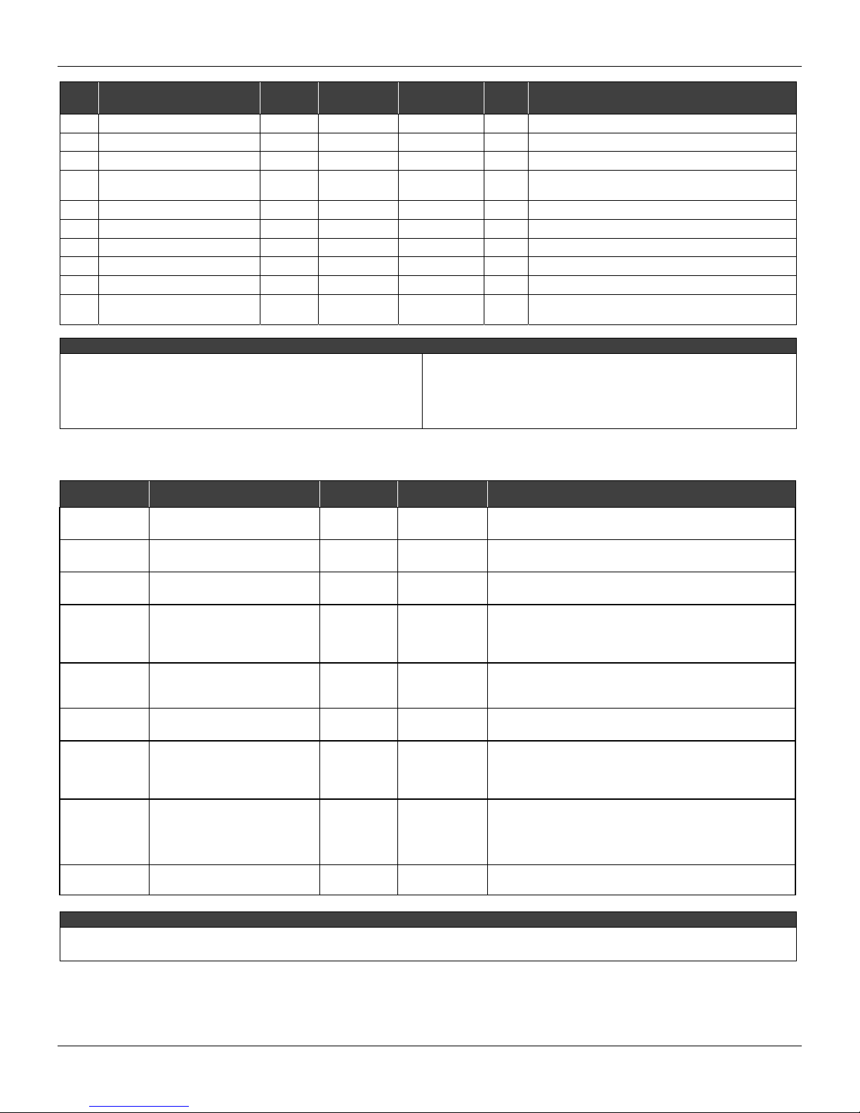
HK524"/"Qrgtcvkqp"cpf"Ockpvgpcpeg"Kpuvtwevkqp"Ocpwcn"
Index Parameter
29 CURVE_LENGTH 6
30 CURVE_X 6 % % Input points of characterization curve.
31 CURVE_Y 6
32 FEEDBACK_CAL 4 0 mA
33 CAL_CONTROL 4
34 CAL_POINT_HI_BACKUP
35 CAL_POINT_LO_ BACKUP
35 CAL_POINT_HI_FACTORY
37 CAL_POINT_LO_FACTORY
Manual
Section
Valid Range
2 a 8
En/Dis
Default/ Init
Value
8 None Indicates the length of characterization curve.
% % Output points of characterization curve.
Disable None Enable and disable for calibration process.
20.0 mA Indicates the backup for high calibration point.
4.0 mA Indicates the last high calibration point.
20.0 mA Indicates the last low calibration point.
4.0 mA Indicates the low factory calibration point.
Unit Description
The measured current value used by the calibration
method.
38 ORDERING_CODE
AUTO - Automatic
FACTORY - Standard of factory
NULL - No standard value
NONE - No unit or no value
Na - Non-dimentional parameter
Fkurnc{"Dnqem"Rctcogvgtu"
Index Parameter
7
8
9
10
11
12
13
14
63
Monit – Monitoring
Mnem – Mnemonic
BLOCK_TAG_PARAM
INDEX_RELATIVE
SUB_INDEX
MNEMONIC
INC_DEC
DECIMAL_POINT_NUMBER
ACCESS
ALPHA_NUM
DISPLAY_REFRESH
None Indicates information about factory production.
CAPTION
E - Parameter list
FVR - Final_Value_Range,
True/False - Accepts true/false values
En/Dis - Enables/Disables parameter
Manual
Section
Range/Options Description
3
3 0 a 65535
6 1 a 255
6
6
6
6
3
0 a 4
Monit/
Action
Mnem/
Value
True/
False
CAPTION
This is a tag of the block to which the parameter belongs to
use up to a maximum of 32 characters.
This is the index related to the parameter to be actuated or
viewed (1, 2...).
To visualize a certain tag, opt for the index relative equal to
zero, and for the sub-index equal to one.
This is the mnemonic for the parameter identification
(maximum of 16 characters). Choose the mnemonic,
preferably with no more than 5 characters because, this
way, it will not necessary to rotate it on display.
It is the increment and decrement in decimal units when the
parameter is Float or Float Status time, or integer, when the
parameter is in whole units.
This is the number of digits after the decimal point (0 to 3
decimal digits)
The access allows the user to read, in the case of the
“Monitoring” option, and to write when “action” option is
selected, and then the display will show the increment and
decrement arrows.
These parameters include two options: value and
mnemonic. In option value it is possible to display data both
in the alphanumeric and in the numeric fields, this way, in
the case of a data higher than 10000, it will be shown in the
alphanumeric field.
It allows updating the local adjustment tree.
XKKK"
Page 9

HQWPFCVKQP"Hkgnfdwu"Dnqemu"
Fkcipquvke"Dnqem"Rctcogvgtu"
Index Parameter
1 ST_REV 0 Null 2 TAG_DESC Spaces Na 3 STRATEGY 0 Null 4 ALERT_KEY 1 a 255 0 Null 5 MODE_BLK O/S Na See Mode Parameter.
6 BLOCK_ERR 5 E
7 EXE_TIME_TAG 5 Spaces Na
8 MIN_EXE_TIME 5 +INF ms Minimum execution time of the selected block.
9 CUR_EXE_TIME 5 0 ms Current execution time of the selected block.
10 MAX_EXE_TIME 0 ms Maximum execution time of the selected block.
11 HW_REV 5 Hardware revision.
12 FIRMWARE_REV 5 Firmware revision.
13 DEV_SN 5 Device serial number.
14 MAIN_BOARD_SN Main board serial number.
15 BEHAVIOR 5
16 PUB_SUB_STATUS
17 LINK_SELECTION
18 LINK_NUMBER Number of the external link selected.
19 LINK_STATUS Status of the external link selected (see table below)
20 LINK_RECOVER
21 BLOCK_ALM Na
22 SAVING_CONFIG
NULL - Has no standard value
Na - Non-dimensional parameter
E - Parameter list.
ms - Milisecond
Manual
Section
Valid Range
0 - Adapted
1 - Spec
0 - bom
1 - ruim
0 - First
1 - Next
2 - Previous
0 - No Action
1 - Action
0 - No save
1 - save
Default/ Init
Value
0 E
E
0 E Select an external link.
No Action E
0 E
Unit Description
Block tag of the selected block to measure the
execution time.
Select the initial values for parameters, there are two
options Adapted and Spec.
Indicate if all external links is good or if at least one is
bad.
Command a recovery process to the external link
selected.
The block alarm is used for all configuration, hardware,
and connection failure or system problems in the block.
The cause of the alert is entered in the subcode field.
The first alert to become active will set the Active status
in the Status attribute. As soon as the Unreported
status is cleared by the alert reporting task, another
block alert may be reported without clearing the Active
status, if the subcode has changed.
It indicates if the device is saving the configuration in a
non-volatile memory.
CAPTION
"
KZ"
Page 10

HK524"/"Qrgtcvkqp"cpf"Ockpvgpcpeg"Kpuvtwevkqp"Ocpwcn"
Z"
Page 11
Kpuvcnncvkqp"Hnqyujggv"
Start
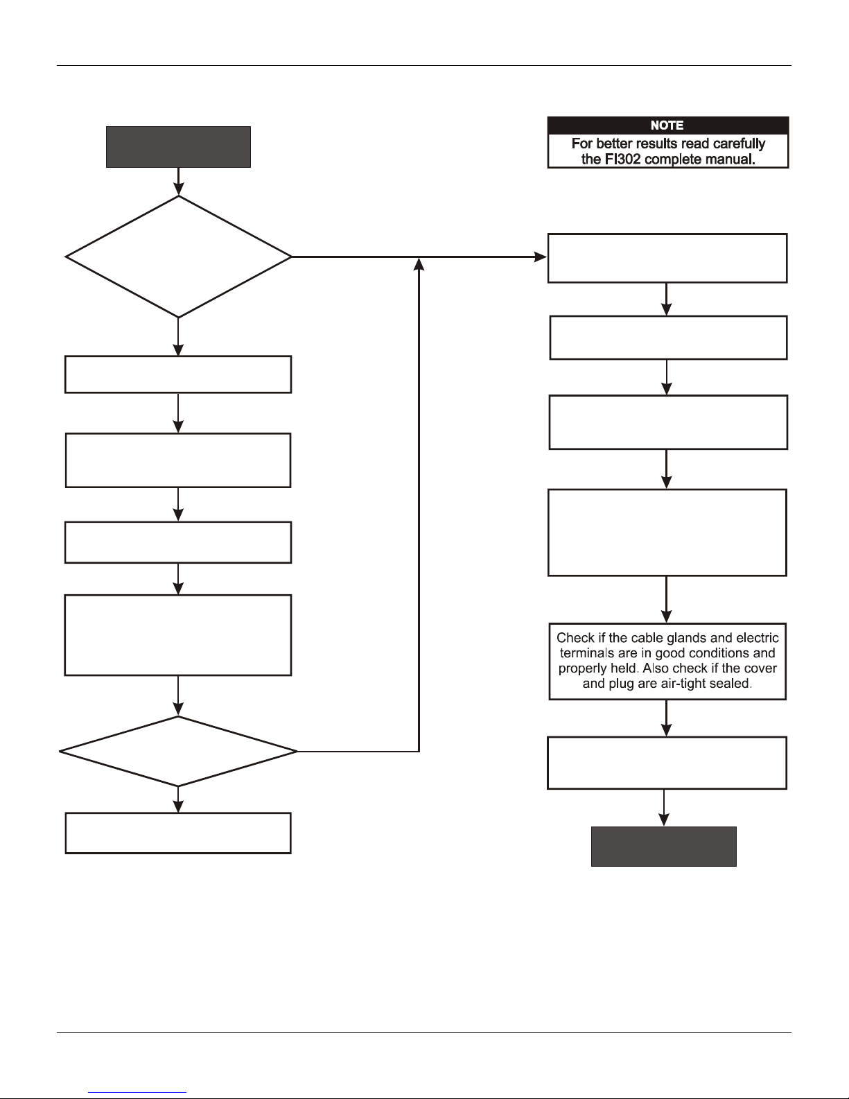
Kpuvcnncvkqp"Hnqyejctv"
Was the converter
configured on the bench
to match the application?
No
Configure the engineering unit.
Configure the terminal(s)
and output scale(s) .
(Section 5 - Calibration)
Configure the LCD reading.
(Section 4 - Configuration)
Simulate the values in the
input according to output scale
and verify the signals of the
4 a 20 mA
output current.
Fieldbus
Yes
Install the converter on the field
following the instructions below.
Install the preferably
converter
on wether-protected areas.
Check the area classification
and its practices.
Install the (mechanically
converter
and electrically) according to the
application after checking the best
position for the LCD
(Section 6 - Maintenance).
Is the indication correct?
No
See section 6 - Maintenance
Yes
Power-up the properly.
converter
FI302 needs a external power supply
for supply the equipment .
4 - 20 mA
OK
ZK"
Page 12

HK524"/"Qrgtcvkqp"cpf"Ockpvgpcpeg"Kpuvtwevkqp"Ocpwcn"
ZKK"
Page 13
Section 1
General
Mounting
INSTALLATION
NOTE
The installation carried out in hazardous areas should follow the recommendations of the IEC60079-14 standard.
The FI302 is a high end device and thus, in order to take advantage to its maximum, the FI302
requires an appropriate installation.
Many factors may affect the converter accuracy, among which environment conditions are the most
difficult to control. In order to reduce the effects from temperature, humidity and vibration, avoid its
installation in aggressive areas.
The effects from temperature variation may be minimized by assembling the converter in areas
protected from weather changes. If necessary, use thermal insulation against external heat sources.
Humidity is harmful to the electric circuits. In areas with high relative humidit y levels, the correct
placing of the housing cover o-ring must be assured and hand-tight shut to press the o-ring. The
housing cover should not be removed on the field so that its threads are not damaged, as they ar e
not protected by painting.
A flexible sealing material should be applied on the electric connections to avoid humidity. See
details on how to connect the FI302 to Fieldbus.
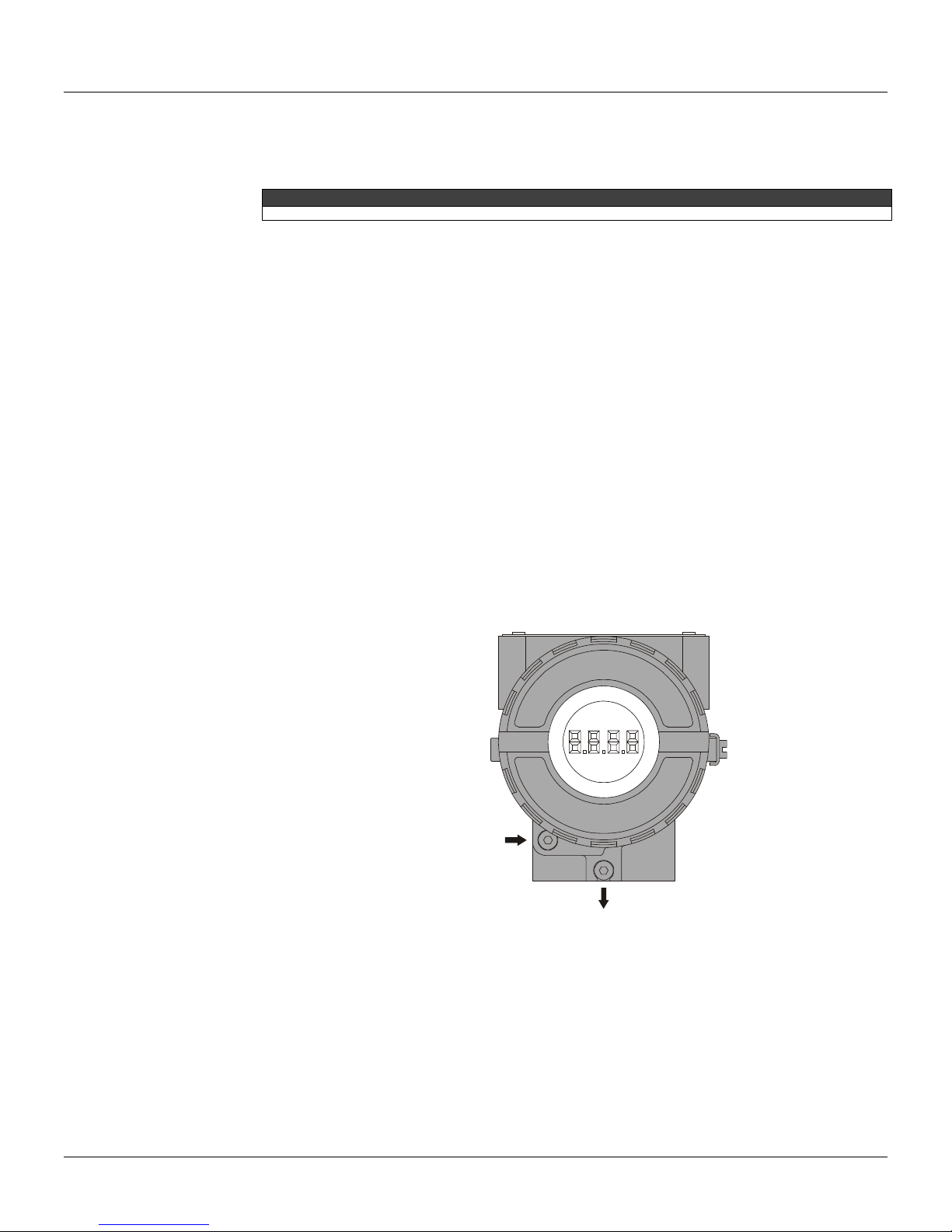
The display may be rotated at 90º to 90º angles for easier visualizati on. See figure 6.2 on section 6
– Maintenance. To access the display, unlock the locking screw on the display cover by rotating it
clockwise. See figure 1.1 to locate the locking screw.
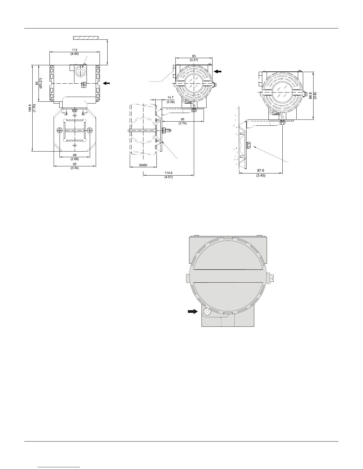
The mounting bracket makes it easier to adjust the converter in several positions, as shown on
Figure 1.2 – Mounting Positions and Dimensional Drawing
COVER
LOCKING
SCREW
HOUSING ROTATION
SET SCREW
Figure 1.1 - Display lid locking screw
1.1
Page 14
FI302 - Operation and Maintenance Instruction Manual
ALLOW 150 MM MINIMUM FOR LOCAL
ZERO AND SPAN ADJUSTMENT WITH
PLUG
MAGNETIC TOOL.
COMMUNICATIONS
TERMINAL
PLUG
CONDUIT
CONNECTION
WALL OR
PANEL MOUNTING
Electric Connection
FOR WALL MOUNTING
2 EXPANSION ANCHOR 2 HEXAGON SCREW -
FOR PANEL MOUNTING
2 BOLT AND NUTS - 1/4”X30
NOT INCLUDED
3/16”X70
S8
PIPE 2"
MOUNTING
BRACKET
Figure 1.2 - Mounting Positions and Dimensional Drawing.
Output Connection
To access the terminal block, loosen the cover locking scre w to release it. Rotate the cover anticlockwise and remove it (See Figure 1.3).
COVER
LOCKING
SCREW
The housing has two threaded openings where to insert the signal cables of the connection terminal
block. The threads allow connecting the wiring conduit or the cable gland.
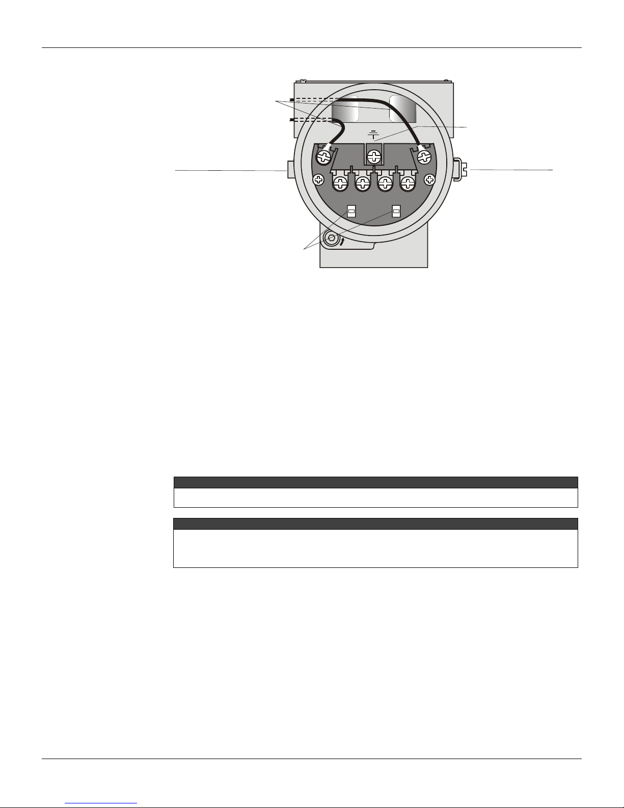
For more convenience, there are three ground terminals: one internal and two externals close to the
terminal block.
Figure 1.4 shows the three terminals of the converter current output channels, which are marked
with numbers 1, 2 and 3. Terminal 4 is the po wer supply common ground to the loop co ntrolled by
the channels. The converter H1 (IEC-61158-2) power supply must be c onnected to the terminals
marked by (+) and (-).
The current output is limited by the power supply voltage on the current loop and by the conditions
of the classified area. Refer to the load curve to determine the maximum equipment quantity allowed
for the bus.
If power fails, the outputs status will be uncertain and in case of communication loss, communication
1.2
Figure 1.3 – Terminal Block Cover Locking Screw
Page 15
Installation
N
A
lacks, the outputs will move to fixed pre-configured values or to safety default values.
BUS AND POWER
SUPPLY T ERMINALS
GROUND CONNECTION
FOR SURGE PROTECTIO
GROUND TERMINAL
(OPTIONAL SCREW)
+
-
GROUND TERMINAL
COMM.
+
3
-
COMMUNICATION
TERMINALS
12
LOCK
Figure 1.4 – Terminal Block
Connecting the FI302 to the FOUNDATION™ fieldbus
The FI302 may be connected to or removed from a fieldbus network in operation. Take due
precaution with this operation and prevent signal cables from touching the shielding, the ground
cables or one another. Insert the FI302 on the ne twork with communication speed equal to its own
(31,25 kbps), FOUNDATION™ fieldbus protocol.
Preparing the FI302 before connecting it to network
The FI302 may be configured on-line or off-line b y a fieldbus configuration like the Smar SYSCO N
installed on a Engineering station, for instance.
Then, use the configuration device to attribute a tag t o the converter, using the “Assign Tag”
option on the menu.
Download the configuration for the equipment or for the entire network.
The Assign Tag may be applied on-line or off-line for specific equipment connected to a fieldbus network
with other equipments.
To attribute a new Tag to the equipment, the system configuration must be changed. This may bring some
inconveniences on the control configuration. For example, the addressees configured on the previous
functional blocks and links are deactivated. Therefore, if the tags are modified, the entire configuration must
be revised and when applicable, the TAG list from OPC Servers shall be updated.
The FI302 is protected against reverse polarity and may support ±35 VDC without causing any
damage, but it will not work under these conditions. Although the FI302 cannot be affected by
polarity, try and keep the polarity in all connections.
In hazardous areas, the number of equipments is limited by the intri nsic safety restrictions. Consult
the documents related to the use of equipment for this area.
NOTE
TTENTION
4
1.3
Page 16
FI302 - Operation and Maintenance Instruction Manual
302 Junctio
r
CS/PLC
DCS/PLC
Interface
(LC700)
Terminator
Terminator
DC Power Supply
(see cargo line)
DC Power Supply
(see cargo line)
DC barrier
DC barrier
The components inside the gray area are normally
located in the control room
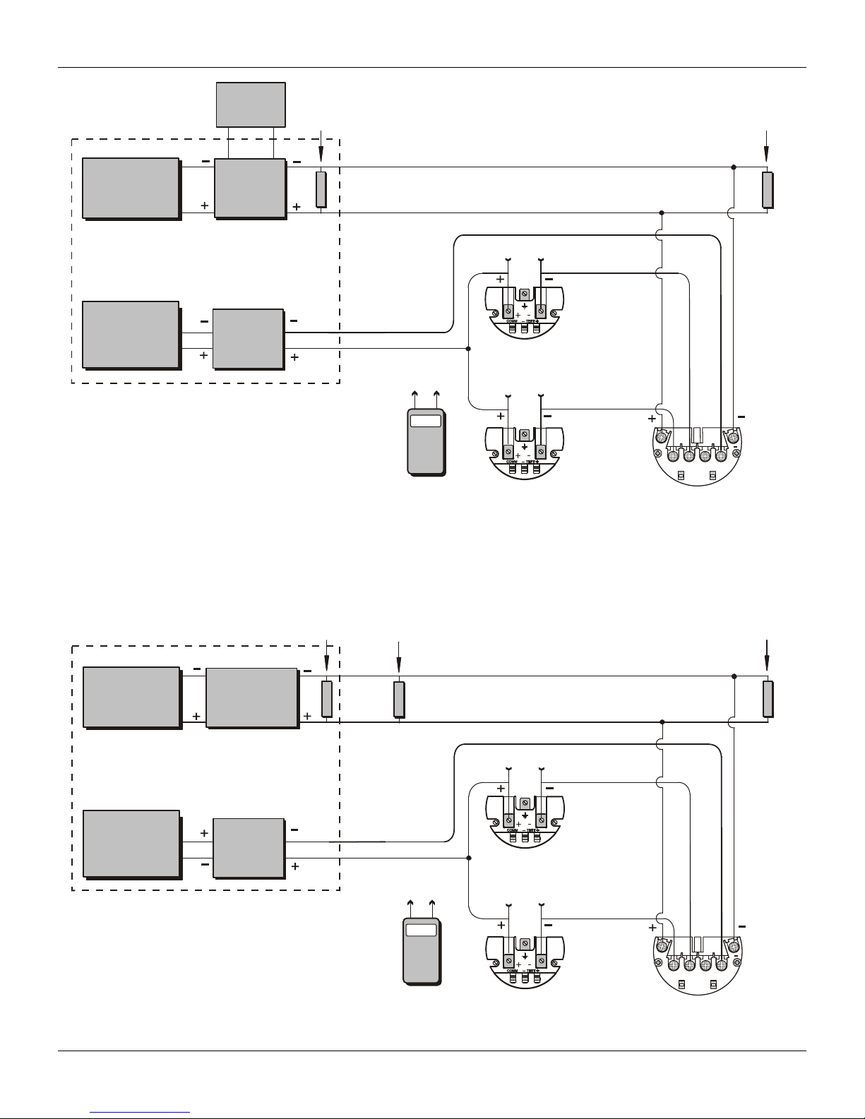
Figure 1.5 – FI302 Output connections for Classified Areas.
The FI302 connection for non-classified areas must follow the diagram on figure 1.6. The three
available output channels may be used for that area.
Terminator
For C1 and C2
HART I.S.
Communicator
D
Interface
(LC700)
COMM
C1 C2
C1
C2
Equipment with
4 – 20 mA Input
Equipment with
Output 2
Output 1
4 – 20 mA Input
+
1234
COMM.
-
+
FI302 Junction Box
Terminato
DC Power Supply
(PS302 ou DF50)
Impedance
Conditioner
Barreira
(DF49, DF53 or
DC
PSI302P)
DC Power Supply
(see cargo line)
DC barrier
The components inside the gray area are normally
located in the control room
1.4
C1 C2
For C1 and C2
ou C3 e C4
C3 C4
HART
Communicator
Figure 1.6 – FI302 Output Connections
COMM
Output 2
Equipment with
4 – 20 mA Input
Output 1
Equipment with
4 – 20 mA Input
+
1234
FI
COMM.
-
+
n Box
Page 17
Installation
CS/PLC
V
30
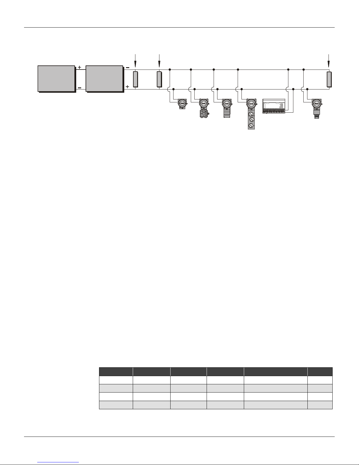
Figure 1.7 shows a typical fieldbus network with equipments for different functions connected.
Terminator
D
Interface
Terminator
DC Power
Supply
(PS302 or Df50)
Impedance
Conditioner
(DF 49, DF53
or PSI302P)
Power Consumption
The FI302 converter must be properly powered as follows:
* Minimum 9 V voltage;
* 12 mA Operating Current (lq)
The power supply must provid the minimum voltage wherever theFI302 is located in the H1
segment. An independent power supply shall be used to power the 4 – 20 mA equipments
connected to the converter output.
Low current consumption equipments should be used for intrinsically safety applications. Choose
low resistance cables to reduce drop in voltage on the junction box and on each equipment.
Terminator
The terminators are impedances with the same values as the specific bus impedance to avoid signal
reflection and, consequently their distortion or loss. Each bus segment must have only two
terminators positioned on its ends. Some equipments, especially for power source, output/input,
fieldbus test or PC simulation card, etc, include the option for an internal terminator connection.
Before connecting a terminator to the bus, check if the equipment already has an internal terminator
on one end, and install the other terminator.
Each terminator has a 100 Ohm impedance and the equivalent impedance of both will be 50 Ohm.
The terminator causes a 250- to-500 mV amplitude tension drop on the bus.
Smar has the terminator model BT302.
Cabling
The FOUNDATION™ fieldbus protocol works with several types of cabl e and the best they are, the
longer the lengths and the greater the number of equipments to be connec ted to it. Table 1.1 sho ws
the regular cable types used when installing FOUNDATION™ fieldbus equipments and their
characteristics.
INAINBOUT
smar
DC302-10
0
0
0
1
1
1
STCOM
2
2
2
3
3
FI302
LD302 TP302
Figure 1.7 – Typical Fieldbus Equipment Network
LOAD
FLASH
VEX A INA 1 INA 3 INA 5 INA 7 VEX B INB 1 INB 3 INB 5 INB 7 VEXOUT OUT 1OUT 3 OUT 5 OUT 7 +BUS
INA 0 INA 2 INA 4INA 6 GND A INB 0 INB 2INB 4 INB 6 GND BOUT 0 OUT 2 OUT 4OUT 6 GNDOUT
FY
2
DC302
3
4
4
4
VEXA
5
5
5
VEXB
6
6
6
EXOUT
7
7
7
BUS
Pair Shielding Twisted Size Maximum Length Type
Single Yes Yes
Multicables yes yes
Multicables no yes
Multicables yes no
0,75 mm² 1900 m A
0,32 mm² 1200 m B
0,13 mm² 400 m C
1,25 mm² 200 m D
Table 1.1 – Types of Cables.
LD292
1.5
Page 18
FI302 - Operation and Maintenance Instruction Manual
The length of non-twisted cables decreases regardless of their diameter and shielding (see D t ype data). It
is recommended not to use these cables, but if you do, do not leave them too close to power cables or noisy
equipments.
The Fieldbus Foundation recommends the “A” type cable. Table 1.2 shows its mai n characteristics
for a bus project.
“A” TYPE CABLE
Characteristic impedance on the 31,25 kHz frequency
Maximum attenuation on the 39 kHz frequency 3 dB/km
Maximum capacitance outbalance for shielding 2 nF/km
Maximum DC resistance per conductor lenght 22 Ohm/km
Maximum propagation delay change 1,7 us/km
Conductor transversal area 0,75 mm
Total Cable Length
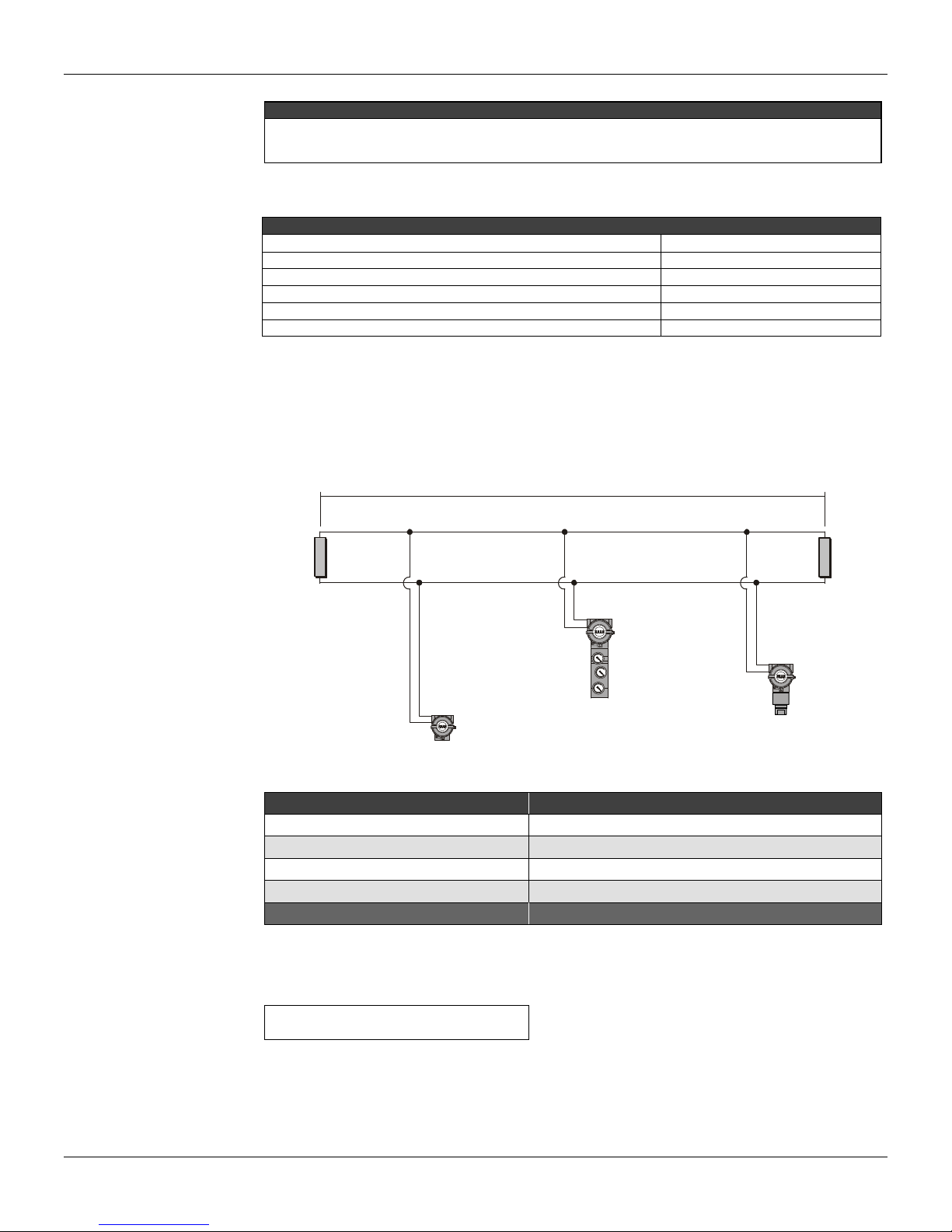
The cable(s) total length vary (ries) according to its/their quality. The total length is the sum of the
trunk and the spur lengths. For instance, use the diagram on figure 1.8 and the table 1.3 to
determine the total length of a hypothetical bus.
NOTE
100 Ohm 20%
Table 1.2 – “A Type” Cable Characteristics
Trunk
2
1.6
Terminator A
Spur 1
FI302
Spur 2
FY302
Figure 1.8 – Total Cable Length
Segment A, B Length
Trunk
Spur 1
Spur 2
Spur 3
Total
Table 1.3 – Examples of Total Cable Lengths
The cable types should combine according to the equation below:
L1 / L1max + L2 / L2max + … < 1
Example: the network has the following cables:
L1: is the type 1 cable length
L2: is the type 2 cable length
L1max: is the type 1 maximum cable length (see table 1.1).
L2max: is the type 2 maximum cable length (see table 1.1).
Terminator B
Spur 3
LD292
240 m
120 m
40 m
80 m
480 m
Page 19

Cable shielding
Commissioning
Installation
L1 = 1000 m of A type cable
L2 = 100 m of B type cable
1000 / 1900 + 100 / 1200 = 0,61
The hypothetical combination on last example satisfies the above equation: 0,61 < 1
Shielding must be used, especially at noisy sites with high EMI/RFI near to the bus. Connect the
spur shielding with the trunk shielding. The shielding should cover a minimum 90% cabl e length to
guarantee good protection.
Grounding
The shielding is grounded only at the power suppl y negative terminal. Do not ground it at the other
terminal, in order to avoid a secondary current circulation that could induce noise onto the bus. If the
cable is not shielded install it on a tray and ground it onl y at one end. Do n ot use shie lding as p ower
conductor. Signal cables should NOT be grounded.
This item will explain the commissioning related to the configuration of the converter in the network.
Before receiving or installing the converter and after the plant’s detailing project conclusion, it is
suggested to initiate the offline configuration. Once accompli shed those steps proceed with the
device configuration download.
In FOUNDATION™ fieldbus the database configuration is made on user-defined tags with no
association with the physical devices. Therefore, the devices must be associated to their respective
configurations.
Each device has a unique Device ID with 32 characters as hardware address, and meant to
distinguish a device from another. This address is engraved on the circuit board by the manufacturer
and cannot be changed. A field device is associated to its config uring system when correlates its
configuration tag to the device ID. If the factory tag is identical to the configured tag on the
configuring systems they will be automatically associated by the configurator system. Once it is
connected to the network, the factory tag may be named, if not done yet.
When all the devices are associated to their respective tags, the configuration may be completely or
partially unloaded on the network equipments.
If possible, use the configuring system to simulate the control and the operation. Then, you may
start, stop and go through the control strategies and check if the plant is operating normally before
the start-up.
Commissioning stages
Con nect the electrically converter to the segment, so that the fieldbus will recognize it as an
equipment with a non-commissioned tag;
Use the configuration software to instantiate the ne wly-connected equipment. This creates ties
between the physical equipment in the plant and the database configur ation;
Upload the equipment internal data o n the configuration system and its strategy control on the
equipment.
NOTE
The Fieldbus requires that the measuring unit be the same, both on the equipment transducer block and the
function blocks, in order to avoid commissioning error.
Use of non-preconfigured to devices
Devices with non-configured tags are configured during commissioning. To do it, follow the
procedure:
Connect each adequate equipment to a fieldbus segm ent. The system will recognize them as
non-commissioned equipments;
Instantiate each equipment on the adequate segment in the configuration software;
Name a TAG to the specific device according to the plant process flowchart (P&ID);
Download the configuration to the equipment.
1.7
Page 20

FI302 - Operation and Maintenance Instruction Manual
Use of preconfigured equipments
The devices with preconfigured tags identify themselves automatically with the configuration and
save commissioning time. The user must simply install them and check when they appear on the
system configurator screen.
Each preconfigured device must be installed on the specific plant site where it was configured for.
Linking Device
The linking device, for instance, the Smar DFI302 or other interfac e, addresses all the devices on
each network automatically. For practical purpose, the node address may be hidden, once it is not
of interest to most users, whose interaction is based on tags. Ho wever, the node addres s is t ypic all y
shown on the live list for the use of specialists. As a result, the Foundation Fieldbus devices may be
commissioned directly from the control room. Once the device is connected to the network it will b e
detected in seconds. The devices may be connected or dis connected at any time without disturb ing
the network.
Error monitoring and detection with Live List
If the device does not appear on the configuration system live list, it most probably was connected to
the wrong network or was not commissioned. In this case, it may b e located in the live list of the
others networks. Another possibility is that the device cable is not conne cted or the device is not
operating properly. The live list, thus, is an excellent commissioning tool, as it facilitates checking
the cable connection to the field devices. To make sure that a device was not mistaken for another
on the same network or that it was installed at the wrong place, the device may be disconnected
temporarily from the network, so that the user check if the right tag disappears from the live list.
For more safety, use the configuration system to obtain detailed ID information from any device
connected to the network. This information helps checking the tag, the description, the
manufacturer, the type, the version and instrument general conditi on in order to confirm if it is the
right device and if it is working properly.
Installation in Hazardous Areas
Explosions could result in death or serious injury, besides financial damage. Installation of this
converter in explosive areas must be carried out in accordance with the local standards and the
protection type adopted .Before continuing the i nstallation make sure the certificate parameters are
In accordance with the classified area where the equipment will be installed.
The instrument modification or parts replacement suppl ied by other than authorized representativ e
of Smar is prohibited and will void the certification.
The converters are marked with options of the protection type. T he certification is valid only when
the protection type is indicated by the user. Once a particular type of protection is selected, any
other type of protection can not be used.
The electronic housing and the sensor installed in haz ardou s areas must h ave a minim um of 6 full y
engaged threads. Lock the housing using the locking screw (Figure 1.3).
The cover must be tighten with at least 8 turns to avoi d the penetration of humidity or corrosive
gases. The cover must be tighten until it touches the housing. Then, tight en more 1/3 turn (12 0) to
guarantee the sealing. Lock the covers using the locking screw (Figure 1.3).
Consult the Appendix A for further information about certification.
WARNING
1.8
Page 21

Explosion/Flame Proof
In Explosion-Proof installations the cable entries must be connected or closed using metal cable
gland and metal blanking plug, both with at least IP66 and Ex-d certification.
The standard plugs provided by Smar are certified accor ding to CEPEL certificate. If the plug
needs to be replaced, a certified plug must be used.
The electrical connection with NPT thread must use waterproofing sealant. A non-hardening
silicone sealant is recommended.
For NEMKO ATEX certificate please to follow the installation guidelines in hazardo us locations
below: Group II Category 2G, Ex d, Group IIC, Temperature Class T6, EPL Gb U = 28VDC
Ambient Temperature: -20 to 60ºC for T6
Environmental Protection: IP66/687 or IP66W/687W
The electrical connection available are ½ - 14NPT and M20x1,5.
Cable entries must be connected or closed using m etal cable gland and metal blanking plug,
both with at least IP66 and Ex-d certification or any appropriate ATEX approved metal cable
gland and metal blanking plug. Do not remove the transmitter covers when power is ON.
Intrinsically Safe
In hazardous zones with intrinsically safe or non-incendive requirements, the circuit entity
parameters and applicable installation procedures must be observed.
To protect the application the transmitter must be connected to a barrier. Match the parameters
between barrier and the equipment (Consider the cable parameters). Associated apparatus
ground bus shall be insulated from panels and mounting enclosures. Shield is optional. If used, be
sure to insulate the end not grounded. Cable capacitance and inductance plus Ci and Li must be
smaller than Co and Lo of the associated Apparatus.
It is not recommended to remove the transmitter cover when the power is ON.
Installation
WARNING
WARNING
1.9
Page 22

FI302 - Operation and Maintenance Instruction Manual
1.10
Page 23
Section 2
4
FUNCTIONAL DESCRIPTION
Functional Description
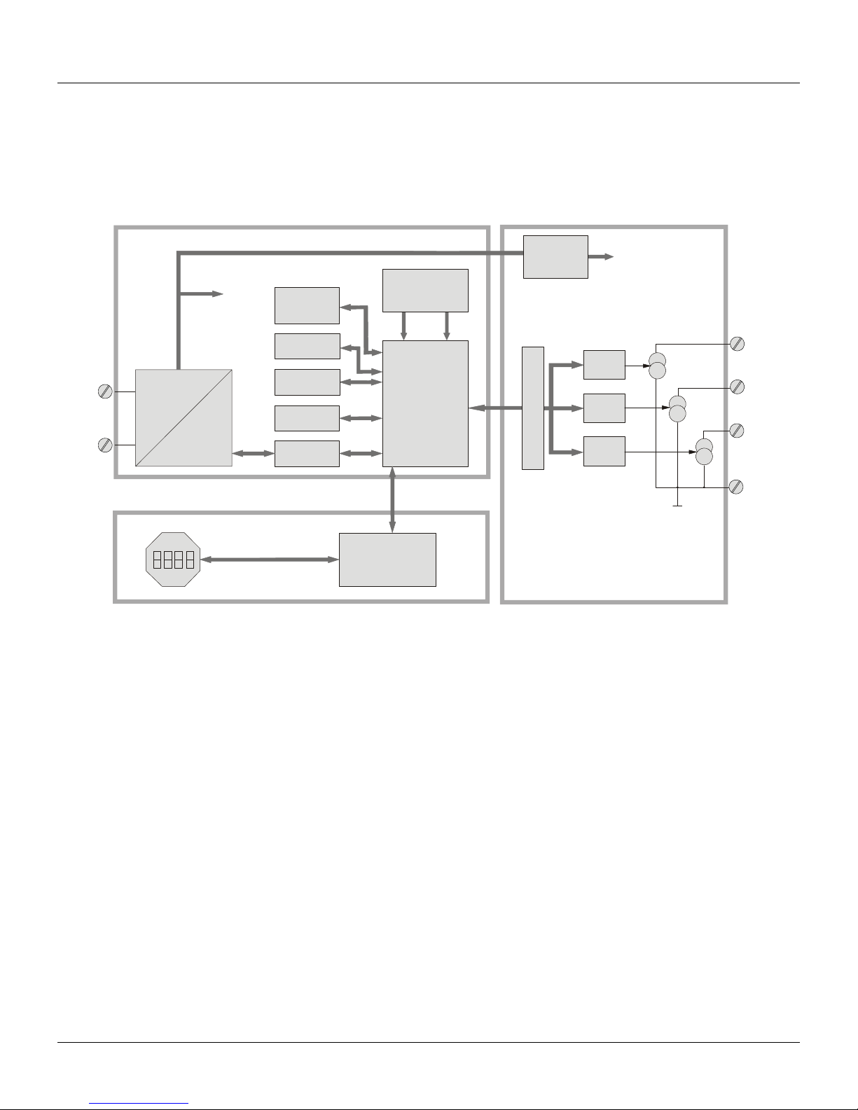
See Figure 2.1.
MAIN CIRCUIT BOARD OUTPUT CIRCUIT BOARD
POWER
ISOLATION
POWER
SUPLLY
SIGNAL
SHAPING
SUPLLY
FIRMWARE
DOWNLOAD
INTERFACE
EPROM
FLASH
RAM
CONTROLER
COMUNICATION
LOCAL ADJUST
CPU
. EEPROM
. RAM
SIGNAL ISOLATION
CORRENT CONTROL
1
D/A
2
D/A
3
D/A
DISPLAY BOARD
DISPLAY
CONTROLLER
Figure 2.1 – FI302 Block Diagram
D/A
Receives signal from the CPU and converts it to an analog signal to be used by the current control
Current Control
Controls the channel current according to the data received from the CPU.
Signal Isolator
Isolates the data signal between the output and the CPU.
Central Processing Unit (CPU), RAM and FLASH
The CPU is the converter intelligent part, and is responsible for the management and operation of
the blocks, auto-diagnosis and communication. The program is stored in FLASH memory. For the
temporary storing of data there is a RAM. The R AM data will be lost if energy fails, although the
device has a non-volatile EEPROM where the valid data are stored, as for calibration, config uration
and identification.
Communication Controller
It controls the line activity, modulates and demodulates communication signals a nd inserts or delete
initial and final delimiters.
Power Supply
Uses energy from the control loop to power the converter circuit.
Power Insulation
The power must be insulated as the output signals sent or received by the output
2.1
Page 24

FI302 - Operation and Maintenance Instruction Manual
Signal Conditioner
Prepares the signals from the network or from the communication co ntroller at acceptable levels by
the communication controller or the fieldbus network, respectively.
Display Controller
Receives CPU data and controls the Liquid Crystal Display.
Local Adjustment
The power must be insulated once signals are sent and received by the output.
2.2
Page 25
Section 3
OPERATION
Liquid Crystal Display
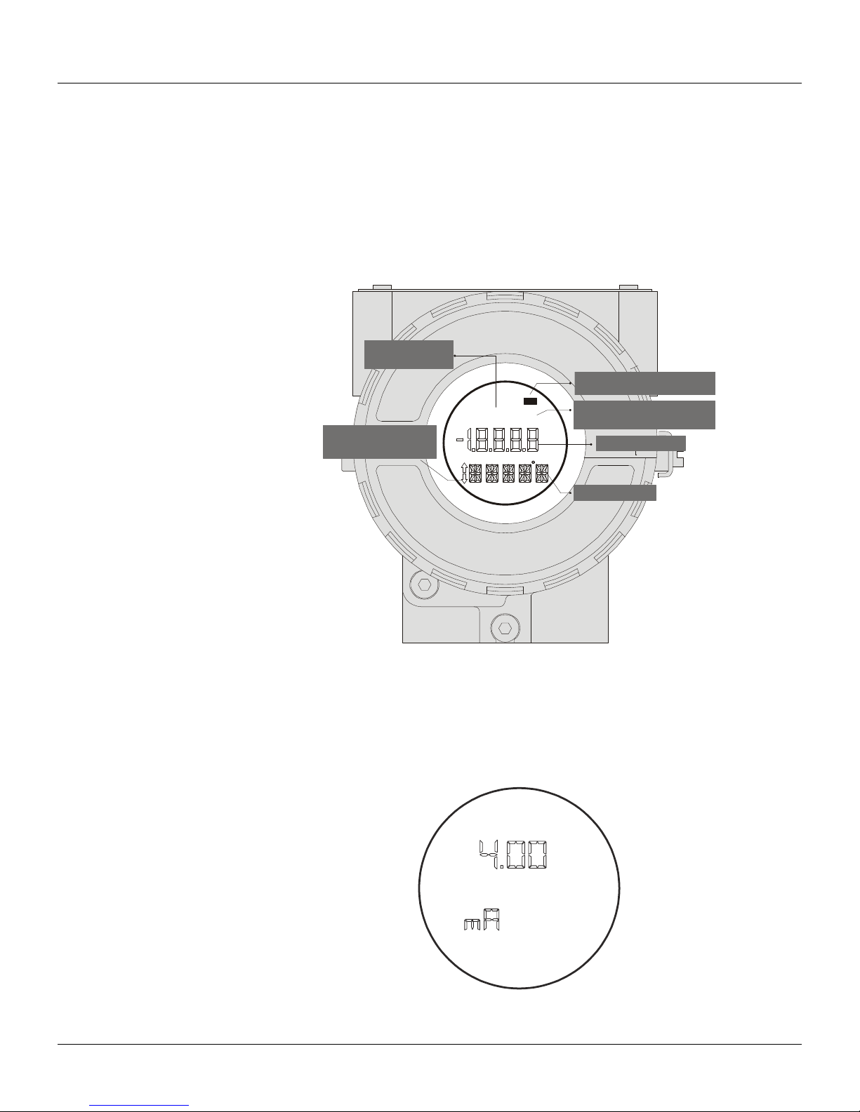
The liquid crystal display shows up to three variables that ma y be selected by the user. When two or
three variables are chosen, the display will alternate the sampling from both with an interval of
approximately 3 seconds.
The LCD is made of a field with 4½ numerical digits, a field with 5 alphanumeric digits and an
information field, as shown on Figure 3.1.
INDICATES THAT THE
COMMUNICATION IS
ACTIVE
INDICATES THE POSSIBILITY
FOR VARIABLE/MODE
ADJUSTMENT/CHANGE
F (t)
INDICATES THAT THE OPERATION
IS LOCALLY ADJUSTED
MD
5
INDICATES THAT THE EEPROM
IS ACTIVE AND THE OPERATION
IS SAVED
VARIABLE FIELD
Monitoring
MNEMONIC FIELD
Figure 3.1 - Display
During normal operation, the FI302 is in monitoring mode and the ind ication alternates between the
variables, as configured by the user. See Figure 3.2. The display shows the engineering units,
values and parameters simultaneously with the majorit y of status indicators, depending o n the local
adjustment configuration.
Figure 3.2 – Typical Monitoring Mode displaying the current inferior value, namely 4.0 mA.
3.1
Page 26

FI302 - Operation and Maintenance Instruction Manual
The monitoring mode is interrupted when the us er makes the local adjustment. The display also
shows messages and errors (See Table 3.1).
DISPLAY DESCRIPTION
Init , FI302 & Version The FI302 is powered and initiated
Blk OOS OOS block not configured and link ineffective
bad Communication or signal failure or bad signal
Table 3.1 – Display Messages and Errors.
3.2
Page 27

Section 4
Transducer Block
CONFIGURATION
The FI302 may be configured b y any Foundation Fieldbus configuration tool or by an operational
console.
The FI302 has three output transducer blocks, one reso urce block, one display block, one
diagnostic block and other instant able function blocks.
This manual deals with the parameters of transducer bl ocks, display block and diagnostic block. The
function blocks are described in the specific function block manual.
The transducer block insulates the hardware input/output function block like sensors and actuators.
The transducer blocks controls the input and output access through the specific manufacturer
implementation.
Usually, transducer block execute linearization function, characterization.
The connection between the transducer block and function blocks is called channel.
How to Configure a Transducer Block
When instantiating the FI302 on the configuration tool, the transducer block is automatically
instantiated.
The Transducer block has an algorithm, an internal param eter group and a ch annel that connects it
to the analog output function block.
The algorithm describes how the transducer transfers information from the hard ware input/output to
other function blocks. The internal parameters, which cannot be linked to other blocks and published
on the link via communication, define the user interface for the transducer block. The y are divided in
Standards that comply with the Foundation Fieldbus standar d and those sp ecified by manufacturers
and made according to their needs.
Every standard routine (e.g. calibration) follows a step by step method, which defines generally the
rules that will help the user.
The transducer, display and diagnostic blocks have several parameters that could be configured.
Here will treat of the most usual. The others are similar.
NOTE
The parameters ending with an “n” mean that they are the same fo r the othe r gr oups, and a re distinguished b y
their group number instead of the letter “n”.
For the FI302 basic configuration, use the Transducer and Display blocks parameters.
The Transducer Block parameters are configured as follows:
MODE_BLOCK
The MODE-BLOCK parameter configures the transducer block mode of oper ation. There are two
options: Out of Service or AUTO (automatic).
TERMINAL_NUMBER
The TERMINAL_NUMBER parameter relates a value for the channel. It starts with 1 to the
transducer number 1 and goes up to 3 to the transducer number 3. The FI302 has 3 current
channels and the current value will be sent internally to a specific trans ducer output from the analo g
output function block. The number of the analog output block (AO) is related to the transducer
terminal number (TERMINAL_NUMBER). The channels with numbers 1, 2, 3 correspond to the
terminal block numbers 1, 2, 3. Select the combinations (1 - 1), (2 - 2), (3 - 3) for the channel and
the terminal block number where the output will occur (channel number – terminal block number).
The TERMINAL_NUMBER parameter chooses which of the three terminals of the terminal block will
supply the output. At least one of them must be chosen or other wise the FI302 will issue the error
message “Blk_error”.
4.1
Page 28

FI302 - Operation and Maintenance Instruction Manual
Display Block
The FI302 display block shows the variable chosen on m onitoring mode or the option menu on the
local adjustment mode.
The display block is default-configured to make it possible to adjust the Upper Trim (UPPER) and
the Lower Trim (LOWER), to monitor the input transducer output and check the Tag.
The options of the FI302 local adjustment tree may be entirely configured by any fieldbus
configuration tool. Use them for the configuration, but for certain operations the local adjustment is
easier and faster, because it does not depend on network and communication connections. The
parameter options to work with the local adjustment are: Mode Block, Output Monitoring, Tag
Visualization and Tuning Parameter Adjustments.
Before using the magnetic tool for local adjustment, use the fieldb us configuration tool to prepare
the parameters that enable this operation.
How to Configure a Display Block
There are seven parameter groups indexed to the Block_Tag_Param_n param eter that may be
preconfigured by the user to enable a configuration by local adjustment. If it is not necessary to
display this group of tag-indexed parameters, write an invalid tag for the Block_Tag_Param_n
parameter. With this procedure the equipment does not recognize it as a valid parameter nor the
parameters indexed to it.
The Display Block parameters are configured as follows:
MODE_BLOCK
The configuration is identical to the previous transducer block.
BLOCK_TAG_PARAM_n
The is the block tag where the parameter belongs. The FI302 enables inserting up to 7 block tags.
Use a maximum of 32 characters.
INDEX_RELATIVE_n
This is the index related to the parameter that will be activated or visualized (0, 1, 2…6). See the
Function Block manual to know the required in dices, or visualize them on the configurati on tool by
opening the desired block. The FI302 accepts up to 7 parameter indices, configuring up to 7
parameter in the LCD.
DISPLAY_REFRESH
This parameter updates the new configuration.
4.2
Page 29

Section 5
CALIBRATION
If necessary, it is possible to adjust the FI302 output channel current. The trim adjustment is used if
the indication on the transducer block output is different from the reference standard adopted.
Possible causes are:
The user Amperemeter is different from the plant standard.
The converter had its default characterization altered by overload or by the time of use.
To analyze the transducer output calibration, measure the channel output current with an accurate
Amperemeter and compare it with the indication on the FI302. Adjust the trim in case of difference.
The trim may be adjusted in two levels:
Lower Trim: At the range lower level.
Upper Trim: At the range upper level.
These points define the linear output characteristics. The trim adjustments are independent.
The Transducer Block parameters used for the FI302 calibration or current T r im are:
CAL_POINT_HI, CAL_POINT_LO, FEEDBACK_CAL e CAL_CONTROL.
Parameter description:
CAL_POINT_HI
This parameter configures the calibration range upper value.
CAL_POINT_LO
This parameter configures the calibration range lower value.
FEEDBACK_CAL
This is the current measured value used by the calibration method. It is used to apply the current
trim. To apply the lower or upper values, write the value read b y the amperemeter in the parameter
during the calibration of the values. Repeat this operation until the measure is the same as the value
read. See figure 5.1.
CAL_CONTROL
It enables and disables the calibration process with options Enab le and Disable. After initiating the
calibration method, the CAL_CONTROL parameter is used to return to the previous normal
operation.
The calibration will be enabled if the AO bl ock output has a valid value and the status is different
from “Bad”. If “Bad” appears, the message “Calibration Failed” will appear on the XD_ERROR
parameter.
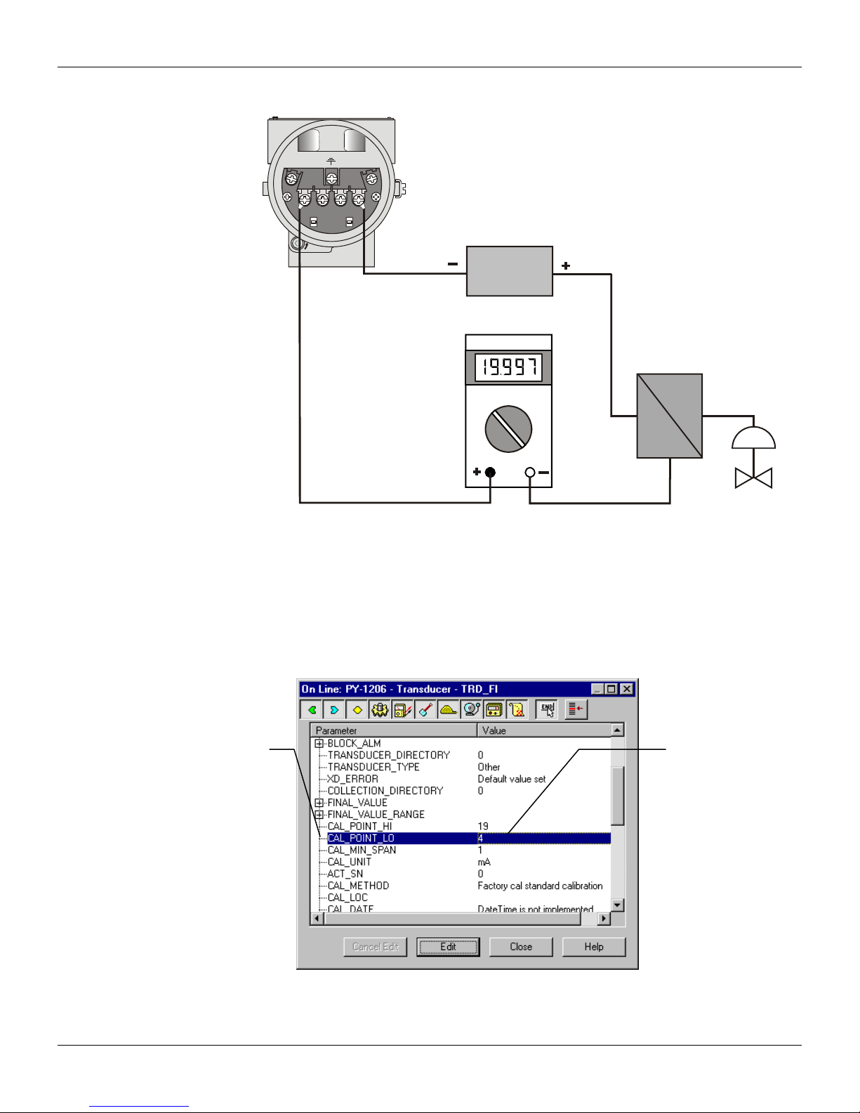
Figure 5.1 shows how to connect the converter to calibrate its lower value on 4 mA and its upper
value on 20mA.
5.1
Page 30
FI302 - Operation and Maintenance Instruction Manual
A
FI302
+
1234
COMM.
+
LOCK
-
-
Power
Power
Supply
Supply
mpere Meter
Amperimeter
P
30 mA
30 mA
I
Figure 5.1 – Current Measuring Connection Diagram
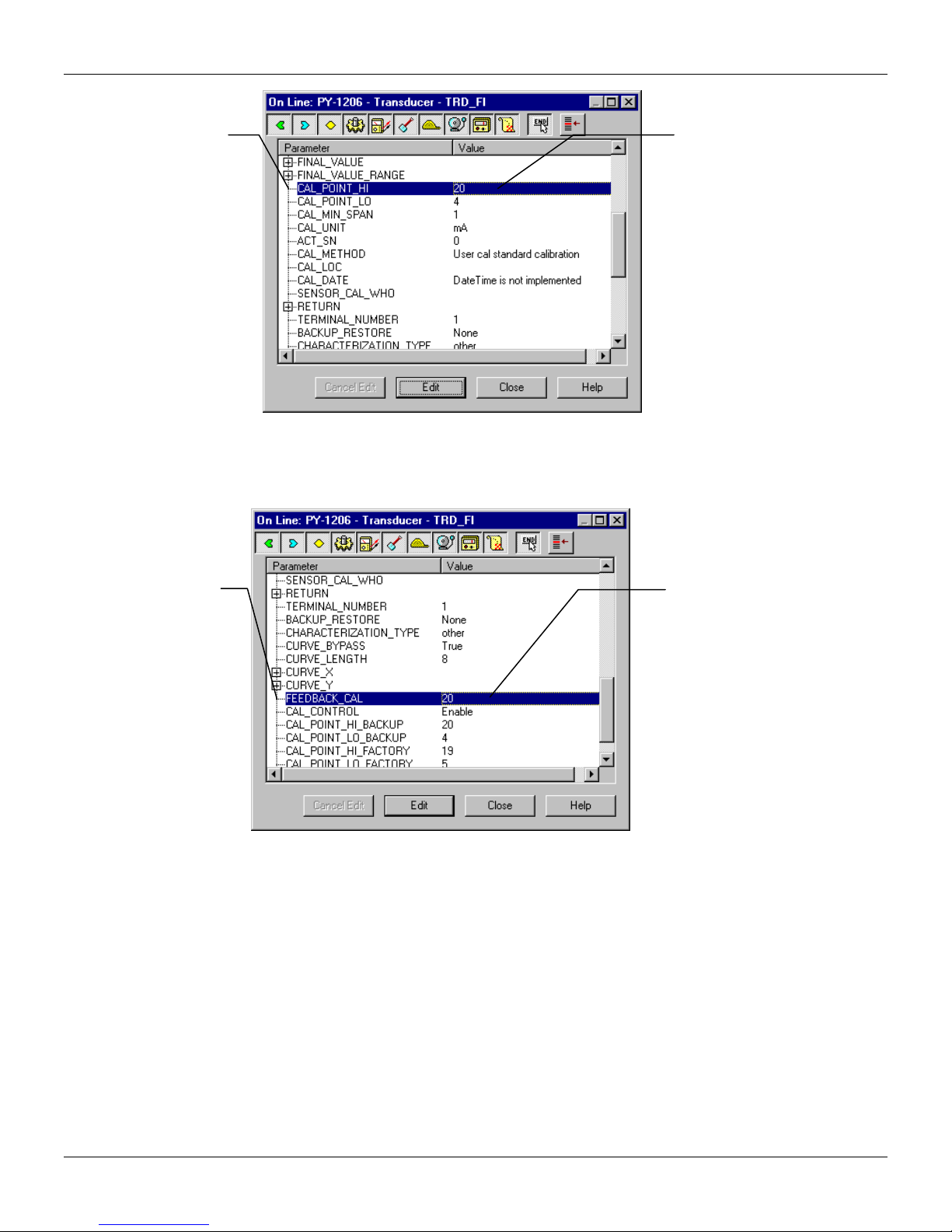
There are two ways to apply the trim: use a magnetic tool for one of them and a fieldbus
configuration tool, like the Smar Syscon for the other.
It is possible to calibrate the conveter by means of parameters CAL_POINT_LO and CAL-POINT HI.
Let’s take the lower value as an example: write 4 mA or the lower value in parameter
CAL_POINT_LO.
This parameter
indicates where the
converter should be
when the setpoint
lower value is 0%.
5.2
The desired value
should be
entered.
Figure 5.2 - Calibrating the CAL_POINT_LO – FI302
Page 31
Calibração
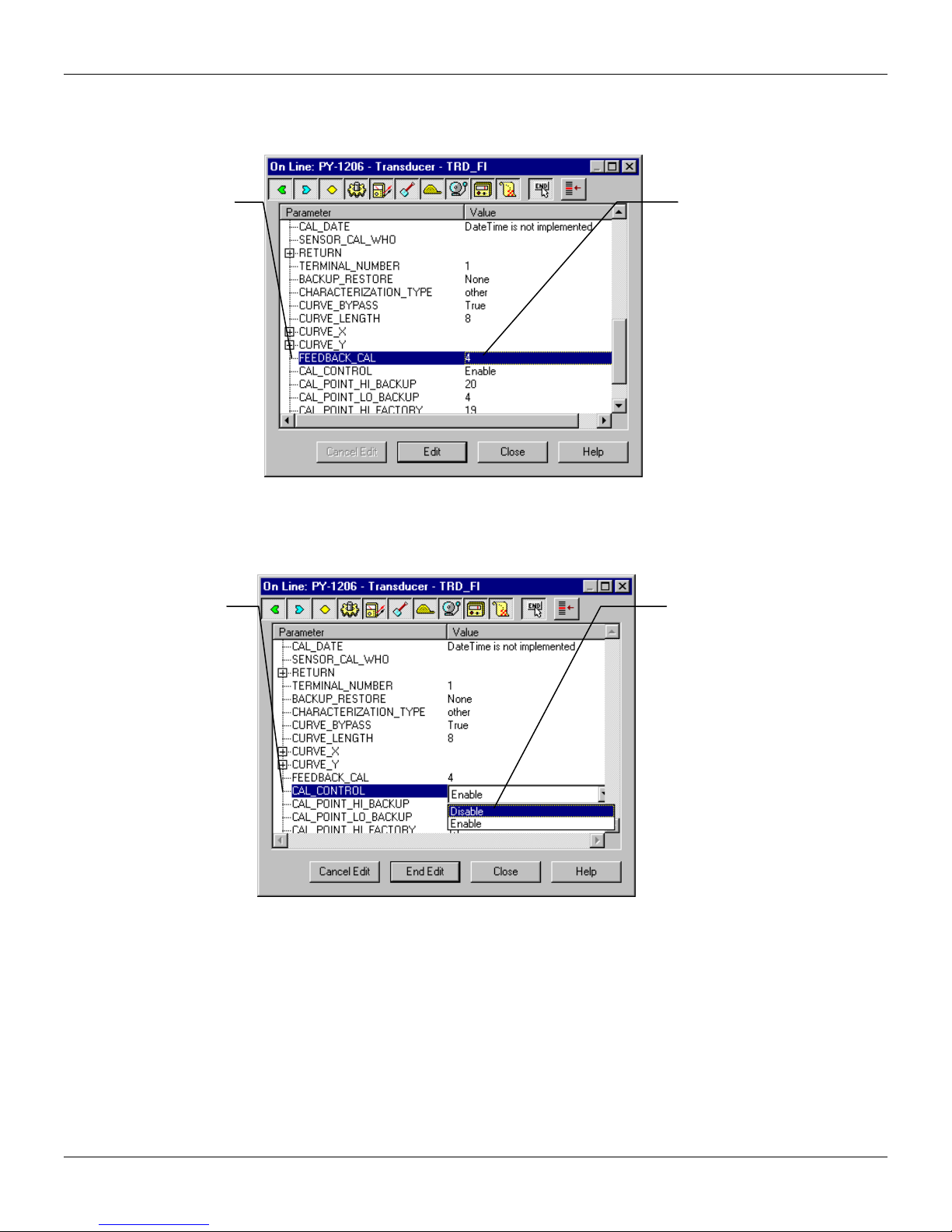
Always keep in mind that, simply by writing in this parameter, the trim procedure is initialized.
Read the current in the multimeter and write that value in param eter FEEDBACK_CAL. Write in this
parameter until it reads 4.0 mA or the lower value readout of the multimeter.
This parameter
should be set with the
actual output current
during the calibration
procedure.
This parameter ends
the calibration
procedure.
The value should
be entered here.
Figure 5.3 - Feedback of Current Lo Value
In order to end the trim procedure, choice DISABLE in the parameter CAL_CONTROL.
The enable option
indicates that the
calibration process is
being done. In order to
finalize its procedure,
the user should set it to
disable.
Let’s take the upper value as an example:
Write 20 mA in parameter CAL_POINT_HI. Always keep in mind that, simply by writing in this
parameter, the trim procedure is initialized.
Figure 5.4 - Closing the Calibration Lo Procedure
5.3
Page 32
FI302 - Operation and Maintenance Instruction Manual
This parameter
indicates where the
converter should be
when the setpoint is
100%.
The desired value
should be entered.
Figure 5.5 - Calibrating the Cal Point Hi – FI302
Read the current in the multimeter and write that value in parameter FEEDBACK_CAL. Write in this
parameter until it reads 20.00 mA or the upper value readout of the multimeter.
This parameter
should be set with
the actual output
current during the
calibration
procedure.
The value
should be
entered here.
Figure 5.6 - Feedback of CAL_POINT_HI – FI302
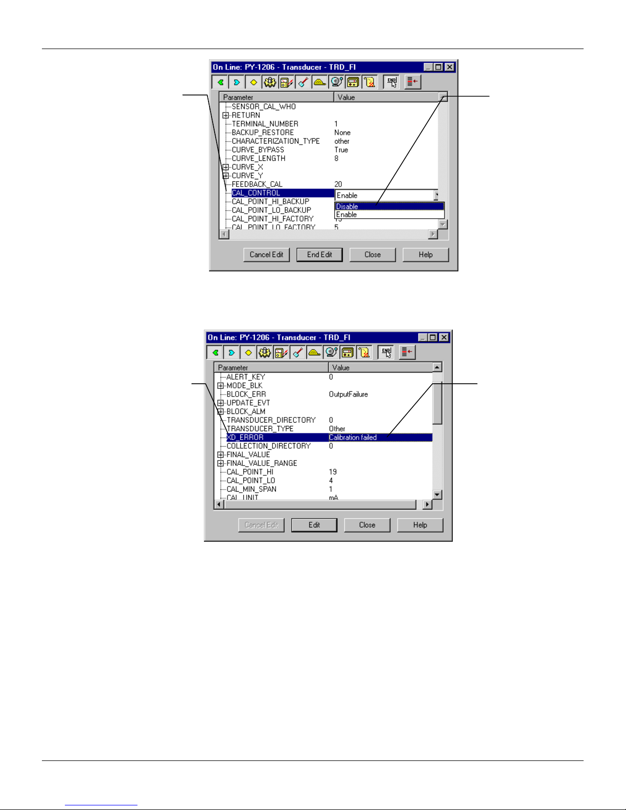
In order to end the trim procedure, choice DISABLE in the parameter CAL_CONTROL.
5.4
Page 33
Calibração
This parameter
ends the
calibration
procedure.
The calibration will be enabled only if th e ou tput of AO bl oc k has a val id v alu e and status differe nt of
"Bad" In this case, the following message can be seen in the parameter XD_ERROR.
This parameter
indicates de Error
Code Operation
associated to
calibration procedure.
The enable option
indicates that the
calibration process is
being done. In order
to finalize its
procedure, the user
should set it to
disable.
Figure 5.7 - Closing the Calibration High Procedure
It indicates that the
calibration
procedure was not
sucessfull.
Figure 5.8- Calibration Error Message – FI302
5.5
Page 34

FI302 - Operation and Maintenance Instruction Manual
5.6
Page 35

Section 6
MAINTENANCE
Equipment installed in hazardous atmospheres must be inspected in compliance with the IEC60079-17
standard.
Diagnostic Block – DIAG
This transducer block provides the following characteristics:
Online measuring time for the functional blocks execution;
Hardware revision
Firmware revision
Equipment serial number
Main board serial number
The BEHAVIOR parameter defines the initial parameter values that will be used after block
instantiation. The Adapted option selects a group of initial values more proper for the parameters,
thus avoiding invalid values. The Spec option also allows defining initial values.
Troubleshooting
Physical Inspection
After connecting the FI302 to the network, if it loses communication or slows down. e.g., due to
multiple tentative communication, the error may be caused by poor installation procedure, by the
configuration or by poor equipment performance.
Causes for communication errors
Badly fit connections
Installation problems, repeated equipment addresses, bad configuration, etc.
Terminator located at the wrong place, with or without terminator
Power supply with too low or unstable voltage value
Too long or too many Spurs
Wrong ground or no ground
Water infiltration in the equipment due to connections with wrong sealing and/or loose clamps
Low isolation
After carrying out the procedures for detecting network defects, act as follows:
Insulate the segment or equipment that causes the problem
Check if the polarity is correct
Check is the address is correct
Check the the Network integrity
Check if the tension on the converter terminals is at least 9.5 V during communication
Remove the equipment to a bench and test it. If it presents malfunctioning, contact Smar.
Parameters used for Troubleshooting
The FI302Transducer Block parameters used for troubleshooting are:
BLOCK_ERR, XD_ERROR, FINAL_VALUE, RETURN e BACKUP_RESTORE
Caution messages may appear on the status of the Return parameter or Block Error parameter, in
given circumstances such as presented below, in two modes, OOS and AUTO.
BLOCK_ERR
This transducer BLOCK_ERR parameter shows the following errors:
Block Configuratio n – When XD_SCALE has an improper range or unit;
NOTE
6.1
Page 36
FI302 - Operation and Maintenance Instruction Manual
Output Failures – When the loop current open;
Out of Service – When the block is on out of service mode (OOS)
Lower
Upper
3.99 < NEW_LOWER < 11.5 mA, otherwise XD_ERROR = 22
12.5 < NEW_UPPER < 20.01 mA, otherwise XD_ERROR = 22
FINAL_VALUE
The desired current value and the status written by the AO block;
RETURN
Current output value coming from the AO block;
RETURN STATUS
The transducer block Return Status indicates the following errors:
Bad::NonSpecific:NotLimited – When the loop current is interrupted (open loop);
XD_ERROR – This parameter is used to indicate the calibration status;
BACKUP_RESTORE
This parameter is used as backup or to recover configuration data.
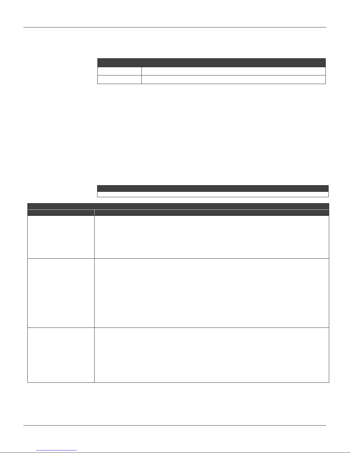
Table 6.1 has the information to determine the converter or network failures.
It is recommended not to repair printed circuit boards. Keep spare parts or buy them from Smar, if necessary.
PROBABLE SOURCE OF ERROR
Symptom Diagnostic
Converter Fieldbus Connections
Check power supply polarity and continuity
No turn on
Power Supply
Check power supply output. The voltage at the FI302 terminal block must be between 9 and 32 Vdc
Electronic circuit failure
Check circuit boards for defects and replace them for spare ones.
Network Connection
Check equipment, power supply and terminator connections.
Network equipment impedance
Check power supply and terminator impedance.
No communication
Converter configuration
Check the converter communication parameters setting
Network Configuration
Check the network communications settings
Electronic Circuit Failure
Replace the main board and the input board matched pairs.
Output Terminal Connection
Check power supply, channels, terminal box polarity and continuity
Incorrect Outputs
(the power supply
indicated aside is for 4-20
mA equipments)
Power Supply
Check power supply output. The FI 302 output voltage must be between 3 and 45 Vdc.
Load Resistance
Must be between 0 and 2000 Ohm. The higher value depends on the output power supply voltage.
Calibration
Check the converter calibration
Table 6.1 – Failure Diagnostic.
Limit Conditions for Calibration
NOTE
6.2
Page 37
If the failure is not on table 6.1 use the Factory Init. The note below shows how to do it.
Use factory init as the last option to recover control over the device when it presents problems related to
function blocks or the communication. Only authorized personnel should do it and the con verter must
be offline. This procedure will enable the standard configuration values of the plant and disabl e the
previous equipment configuration.
To access the letters S and Z use two magnetic screwdrivers and loosen the screw that holds the
identification plate.
Proceed as follows:
1) Turn off the equipment and insert the magnetic screw drive handles in the openings S and Z and leave
them there;
2) Power the equipment;
When the display shows factory init, remove them and wait for the “S” symbol on the right upper corner
to unlit, indicating the end of the operation.
After running the factory init, download partially the configuration, which characterizes the equipment
functional behavior on the fieldbus.
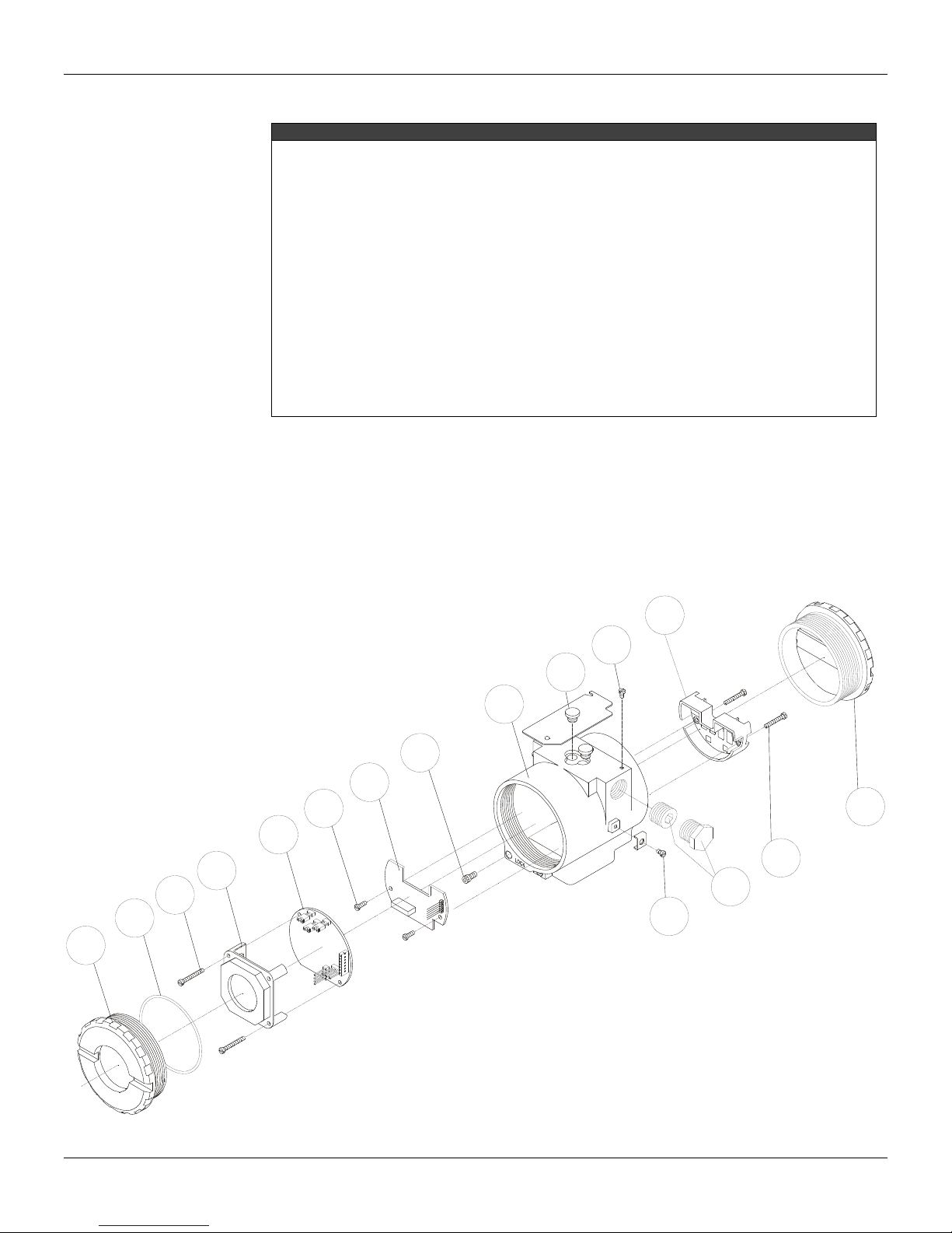
Disassemble Procedure
See Figure 6.1 for guidance on this procedure. Turn off the power supply before disassembling the
converter.
Exploded View
Maintenance
NOTE
12
11
10
9
8
7
6
15
5
14
4
3
2
13
16
1
Figure 6.1 – FI302 Exploded View
6.3
Page 38
FI302 - Operation and Maintenance Instruction Manual
Electronic Circuit
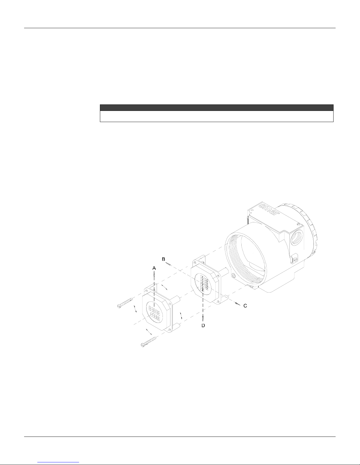
The main board (5) and output board (7) are matched pairs and must be replaced together should it
be needed.
Tighten the locking screw cap (8) located on the opposite side of the enclosure housing marked by
"Field Terminals" and unscrew the cap (1) to access the display and circuit boards. To remove the
motherboard (5) and the display, release the two screws (3) that hold them. Disconnect the display
of the motherboard (5) and that the board's output signal. To remove the entry (7), loosen the
screws (6) that hold the housing (9).
The boards have CMOS components that may be damaged by electrostatic discharges. Follow the right
procedure for handling the CMOS components. Store the circuit boards in electrostatic-proof packaging.
Assembly Procedure
See Figure 6.1 for guidance on this procedure.
Insert the output signal board (7) into the housing (9) and fasten it with its screws.
Insert the main board (5) in the housing, making sure that all the pins are connected.
The display may be mounted in any of the 4 possible positions (see Figure 6.2). The “▲” sign
indicates the display upper position.
Hold firmly the main board and the display with their screws (3).
Fit the cover (1) according to the area classification and lock it with the locking screw (8).
CAUTION
Interchangeability
The output and the main boards are matched pairs, once the calibration data for the output board is
stored in the EEPROM of the main board. If for any reason, boards must be mixed to form a
functional pair, a new calibration procedure must be done in order to guarantee the outputs
accuracy.
6.4
Figure 6.2 – Four Possible Indicator Positions
Page 39
Maintenance
Spares
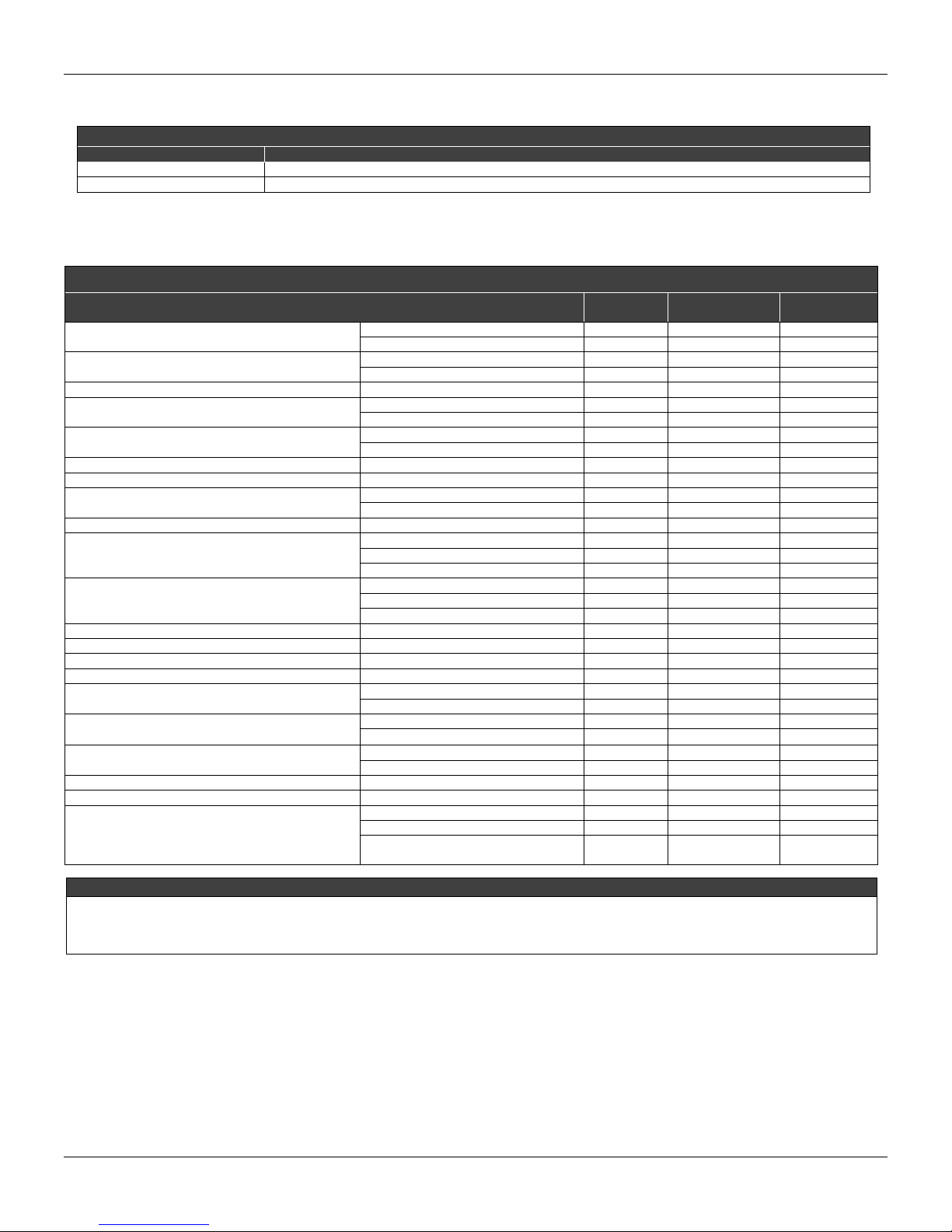
SPARES
ORDER CODE DESCRIPTION
SD1 Magnetic Screwdriver for local adjustment
FDI302 Field device interface
Spare Part List
SPARE PART LIST
DESCRIPTION OF PARTS POSITION CODE
Cover Without Window (Included O-ring)
Cover With Window (Included O-ring)
Sealing ring (Note 2) Cover, Buna-N 2 204-0122 B
Aluminum Housing Main Board Screw
316 Stainless Steel Housing Main Board Screw
Digital Indicator 4 214-0108
Main and Output Board 5 e 7 324-0140 A
Output Board Screw
Cover Locking Screw 8 204-0120
Housing, Aluminum (Note 1)
Housing, 316 Stainless Steel (Note 1)
Local Adjustment Protection Cap 10 204-0114
Identification Plate Screw 11 204-0116
Terminal Block Insulator 12 314-0123
External Ground Screw 13 204-0124
Terminal Block Insulator Screw
Six-Sided Plug 1/2" NPT Internal BR Ex
Six-Sided Plug 1/2" NPT Internal
Six-Sided Plug M20 X 1.5 External BR Ex d 316 Stainless Steel 16 400-0810
Six-Sided Plug PG13.5 External BR Ex d 316 Stainless Steel 16 400-0811
Mounting Bracket for 2” Pipe (Note 3)
1. Includes terminal insulator, bolts (cover lock, grounding and terminal insulator), and I.D. plate without certification.
2. Sealing orings are packed in dozens.
3. Includes U-clamp, nuts, bolts and washers. Spare part list.
4. For category “A” it is recommended to keep in stock 1 set for each 25 installed pairs, and for category “B”, 1 set/50 pairs.
Aluminum 1 e 15 204-0102
316 Stainless Steel 1 e 15 204-0105
Aluminum 1 204-0103
316 Stainless Steel 1 204-0106
Units with indicator 3 304-0118
Units without indicator 3 304-0117
Units with indicator 3 204-0118
Units without indicator 3 204-0117
Aluminum Housing 6 314-0125
316 Stainless Steel Housing 6 214-0125
1/2 - 14 NPT 9 324-0130
M20 x 1.5 9 324-0131
PG 13.5 DIN 9 324-0132
½ - 14 NPT 9 324-0133
M20 x 1.5 9 324-0134
PG 13.5 DIN 9 324-0135
Aluminum Housing 14 304-0119
316 Stainless Steel Housing 14 204-0119
Bichromated Carbon Steel 16 400-0808
Bichromated 304 Stainless Steel 16 400-0809
Bichromated Carbon Steel 16 400-0583-11
Bichromated 304 Stainless Steel 16 400-0583-12
Carbon Steel - 214-0801
316 Stainless Steel - 214-0802
Carbon Steel Bolts, Nuts, Washers
and U-clamp in Stainless Steel
NOTE
- 214-0803
CATEGORY
(NOTE 4)
6.5
Page 40
Section 7
ADVANCED CONFIGURATION
The transducer block allows some configurations through the parameters below that alter the
current output curve.
Parameter description
CHARACTERIZATION_TYPE
Indicates the characterization curve type;
CURVE_BYPASS
Enables and disables the characterization curve;
CURVE_LENGHT
Indicates the number of points the characterization curve;
CURVE_X
Characterization curve input points;
CURVE_Y
Characterization curve output points;
Characterization Curve
The transducer block also has a characterization curve, used to give a determined profile to the
output. This is useful, for example, when the FI302 controls a valve with a non-linear feature. The
characterization curve is applied to the input signal before being converted and sent to the analog
output by the transducer.
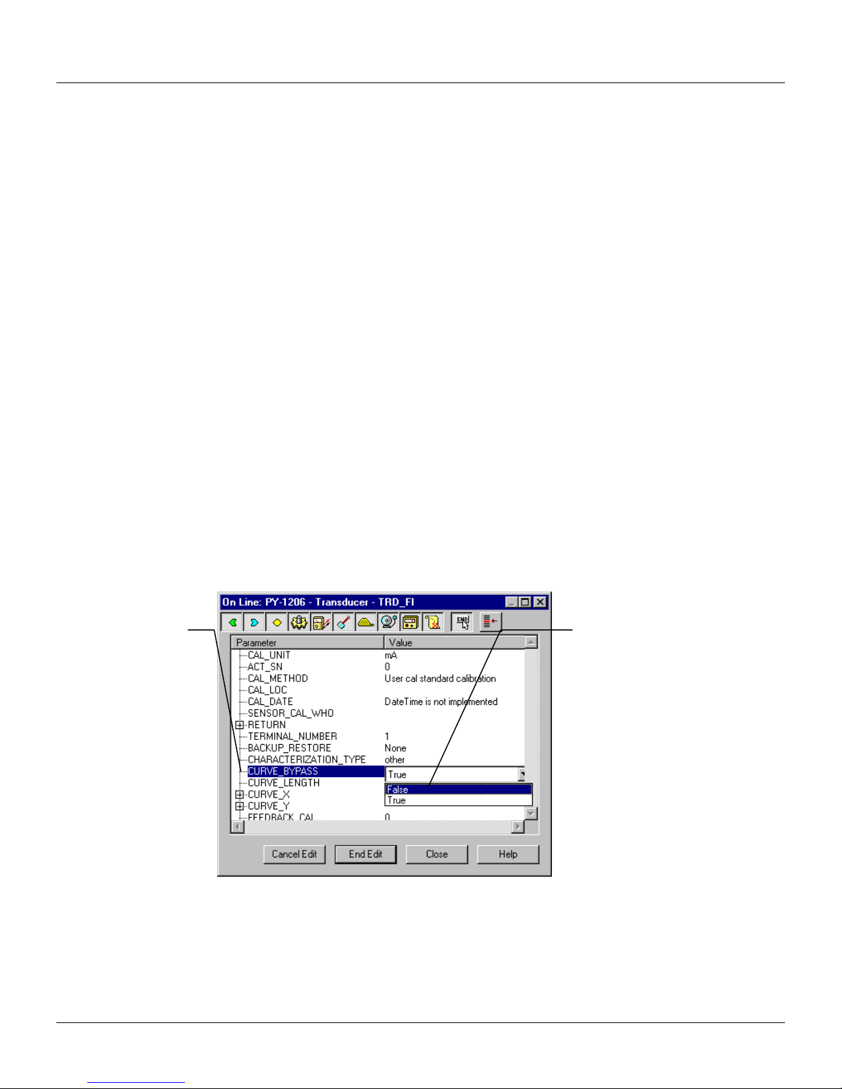
The CURVE_BYPASS parameter determines if the curve will be used or not. If the parameter is a
true Bypass, the curve is not used and the input val ue is transmitted directly to the output current
conversion routine.
"True" means that the
Characterization
Curve will be
bypassed.
This value "False"
enables the
Characterization Curve.
Figure 7.1 - Enabling the Characterization Curve
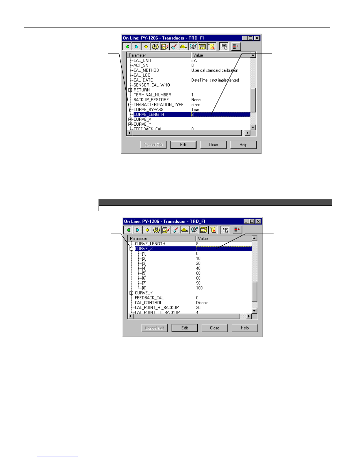
The characterization curve has 8 points. Each point has two coordinates (X and Y). These two
coordinates define the point location in the X – Y space, and the connection of adjacent points with
a linear segment forms the characterization curve. Extreme points are extrapolated.
7.1
Page 41
FI302 - Operation and Maintenance Instruction Manual
This parameter
determines the
number of points valid
and configured.
The maximum number of
points is 8.
These points are numbered from 1 to 8 and are contained in the CURVE_X (abscissas) and
CURVE_Y (ordinates) parameters. CURVE_X par ameter requir es poi nts in crescent order , mean ing
that the subsequent points must be greater than the prece ding ones, or the parameter will not be
accepted. CURVE_Y parameter does not require this, and a non-monotonic curve is allowed.
When writing on CURVE parameters remember to place the point coordinates in the correct order.
Figure 7.2 - Setting the Characterization Curve Length
NOTE
This parameter
defines the
coordinates X
The values should be
configured in crescent
order.
Figure 7.3 - Configuring the Characterization Curve X points
7.2
Page 42
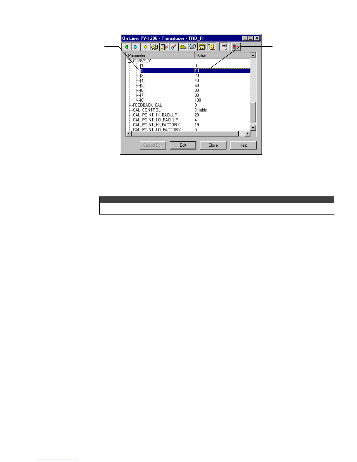
Configuração Avançada
This parameter
defines the
coordinates Y
Figure 7.4 - Configuring the Characterization Curve - Y points
The Display Block allows configure up to three variables her they be shown in the digital indicator,
or a tree with parameters that can be altered via local adjustment. T his configuration is possible
through procedures below:
The parameters with “n” at its end mean that they are the same for other groups and are differentiated by their
group number instead of the letter.
The Display Block parameters are:
SUB_INDEX_n, MNEMONIC_n, INC_DEC_n, DECIMAL_POINT_NUMBER_n e ACCESS_n
SUB_INDEX_n
To visualize a tag choose the relative index equal to zero and the sub index equal to 1
MNEMONIC_n
This mnemonic identifies the parameter (16 characters maximum). Preferably, choose the
mnemonic with up to 5 characters because it will be not necessary to rotate it on the display.
INC_DEC_n
It is the increase and the decrease in decimal units when the parameter is Float, Float Status, or
Integer when the parameter is expressed in total units;
DECIMAL_POINT_NUMBER_n
Number of digits after the decimal point (0 to 3 decimal digits);
ACCESS_n
On Monitoring, the parameter enables only this option and on Action the function shows on the
display the increment and decrement values.
Definition of Parameters and Values
Block_Tag_Param
This is tag of the block to which the parameter belongs. Use up to a maximum of 32 characters.
Index_Relative
This is the index related to the parameter to be actuated or viewed (0, 1, 2…). Refer to the Functio n
Blocks Manual to know the desired indexes, or visualize them on the SYSCON by opening the
desired block.
In case you wish to visualize a certain tag, opt for the index relativ e equal to zero, and for the subindex equal to one (refer to paragraph Structure Block in the Function Blocks Manual).
Sub_Index
It is not necessary to
follow any order. A
monotone curve is
allowed.
FI2EM312
NOTE
7.3
Page 43
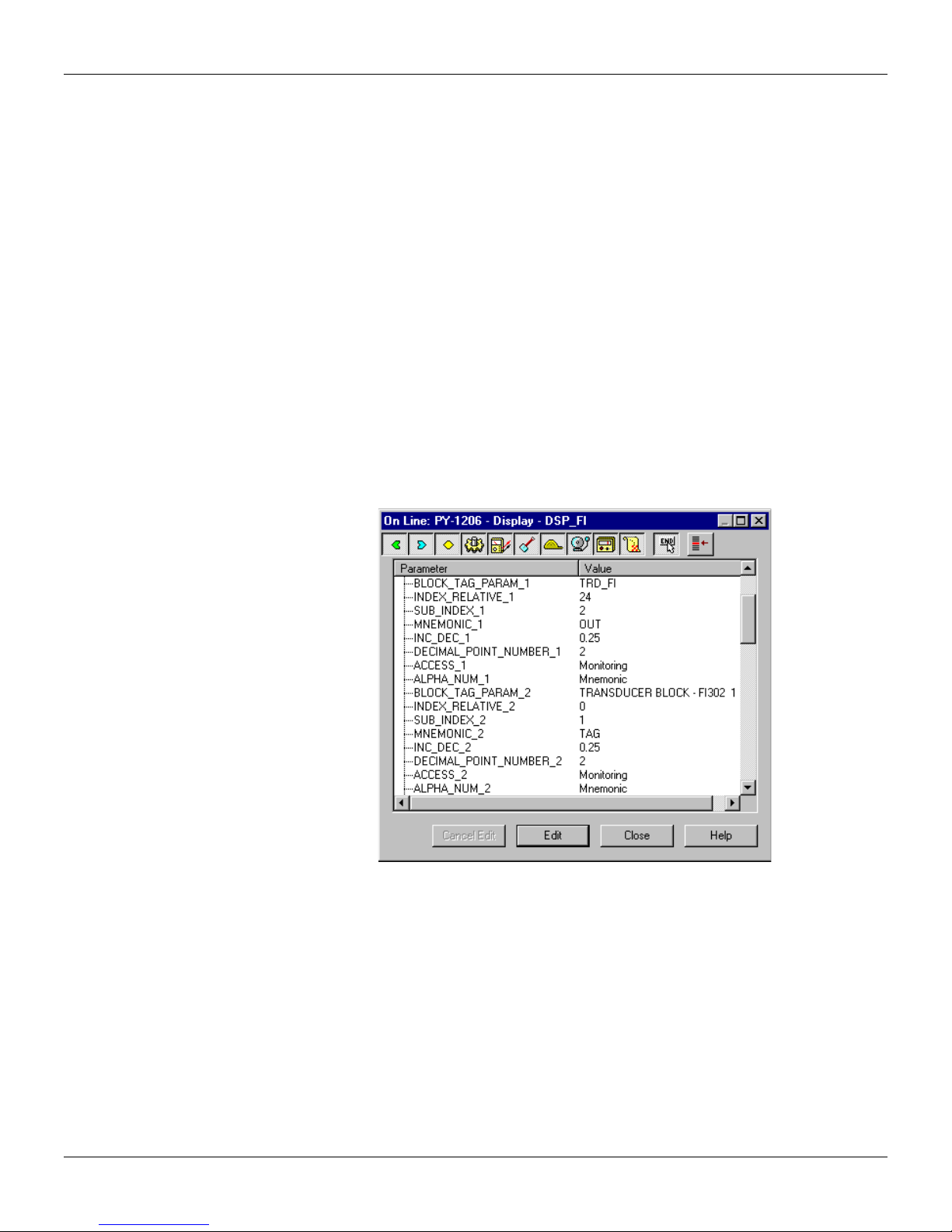
FI302 - Operation and Maintenance Instruction Manual
This is the mnemonic for the parameter identification (it accepts a maximum of 16 ch aracters in the
alphanumeric field of the display). Choose the mnemonic, preferably with no more than 5 characters
because, this way, it will not be necessary to rotate it on the display.
Inc_Dec
It is the increment and decrement in decimal units when the parameter is Float or Float Status time,
or integer, when the parameter is in whole units.
Decimal_Point_Numb.
This is the number of digits after the decimal point (0 to 3 decimal digits).
Access
The access allows the user to read, in the case of the “Monitoring” option, and to write when "action"
option is selected, then the display will show the increment and decrement arrows.
Alpha_Num
These parameters include two options: value and mnemonic . In option va lue, it is possi ble to displ a y
data both in the alphanumeric and in the numeric fields; this way, in the case of a data higher than
10000, it will be shown in the alphanumeric field.
In option mnemonic, the display may show the dat a in the numeric field and the mnemonic in the
alphanumeric field.
In case you wish to visualize a certain tag, opt for the index relativ e equal to zero, and for the subindex equal to one (refer to paragraph Structure Block in the Function Blocks Manual).
7.4
Figure 7.5- Parameters for Local Adjustment Configuration
Page 44
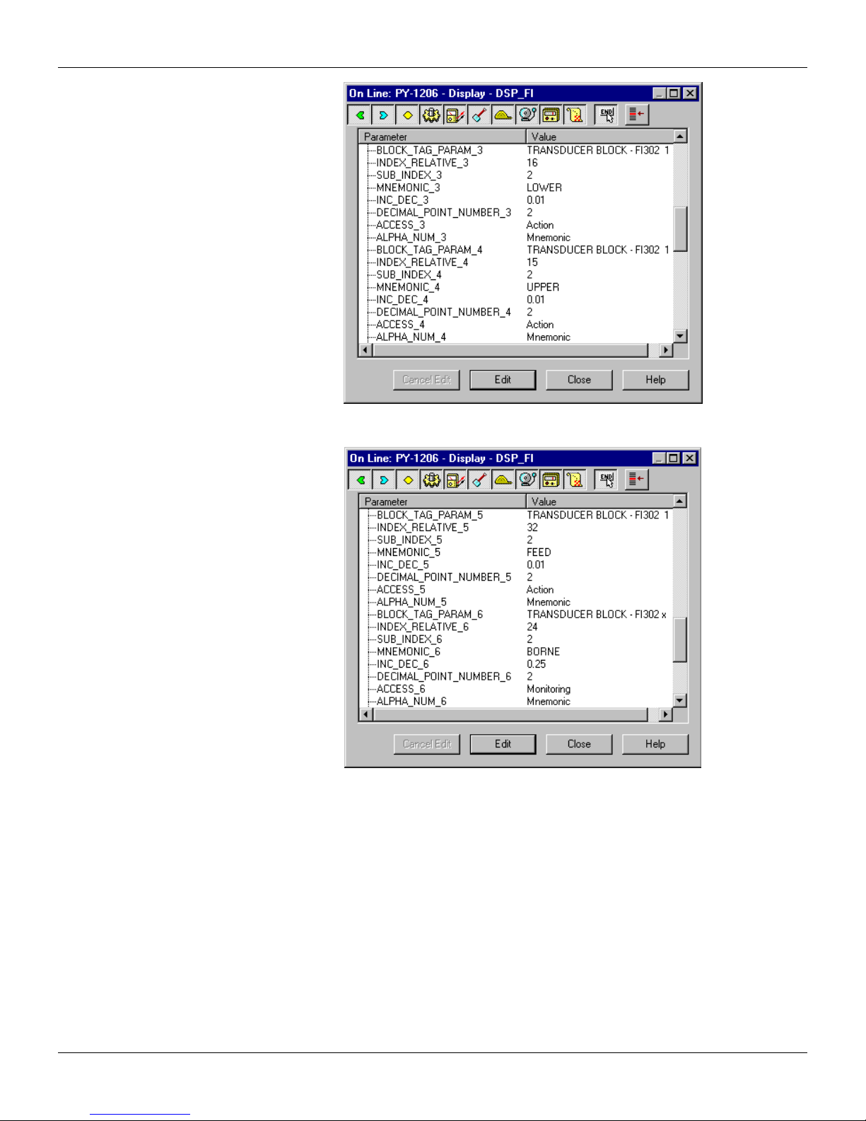
Configuração Avançada
Figure 7.6 - Parameters for Local Adjustment Configuration
Figure 7.7 - Parameters for Local Adjustment Configuration
7.5
Page 45
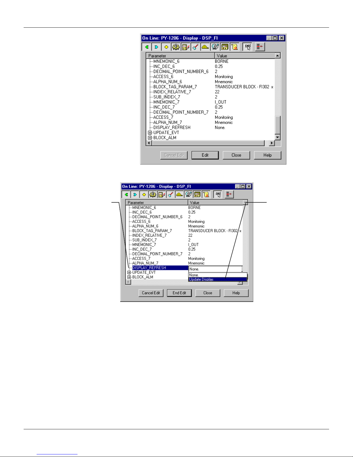
FI302 - Operation and Maintenance Instruction Manual
This parameter updates the
local adjustment programming
tree configured on each
device.
Figure 7.8 - Parameters for Local Adjustment Configuration
The option "update" should be
selected in order to execute the
upgrade of local adjustment
programming tree.
After its step all the parameters
selected will be show on the LCD
display.
Figure 7.9 - Parameters for Local Adjustment Configuration
7.6
Page 46
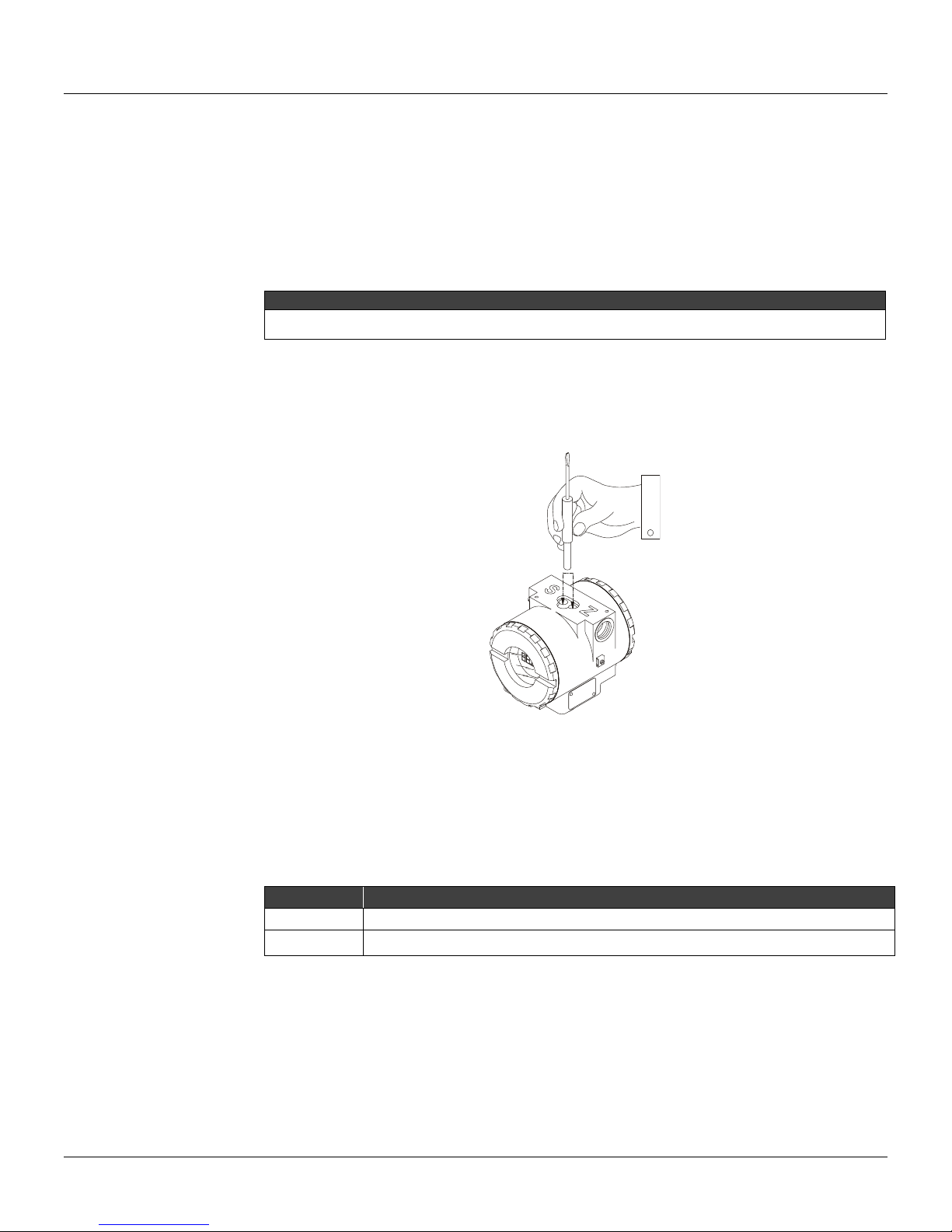
Section 8
LOCAL ADJUSTMENT
When using the local adjustment for calibration, config ure the display block to show the following
parameters: CAL_POINT_HI (UPPER mnemonic), CAL_POINT_LO (LOWER mnemonic) and TAG
(TAG mnemonic).
The FI302 has three output transducers, although only the number 1 leaves Smar with factory
configuration. To configure the other transducers to work with local adjustment use the configuratio n
tool.
NOTE
The Trim mode is removed from local adjustment automatically if the magnetic tool is not used during
approximately 16 seconds.
Under its identification plate, the FI302 has two openings marked with S and Z at their side, giving
access to two Reed Switch magnetic tools. They are activated when the magnetic tool is inserted in
the orifices by its handle (See Figure 8.1).
The magnetic tool permits adjusting most block parameters.
Jumper Configuration
J1 and W1 Ju mpers located on top of the m ain board must be co upled with the main board and the
converter must have a display to show the local adjustment options.
Table 8.1 shows the possible actions applied on openin gs S and Z when the local adjustment is
enabled.
OPENING ACTION
J1 Jumper Connection
If J1 (see figure 8.2) is connected to the ON pins, it will be possible to si mulate values and status
using the SIMULATE parameter on the functional blocks.
S
Z
Figure 8.1 – Local Adjustment Orifices.
Selects the function shown on the display
Initializes the local adjustment and moves through the available options.
Table 8.1 – Function of the Openings on the Housing
8.1
Page 47
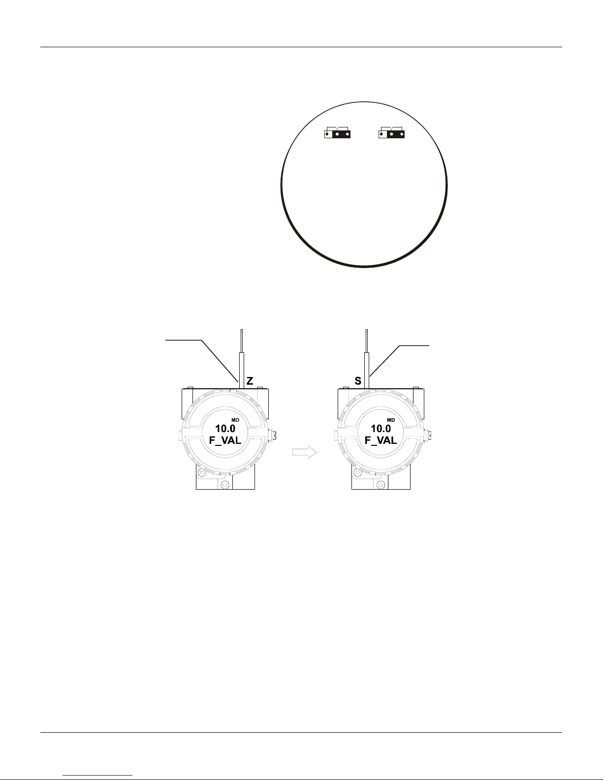
FI302 - Operation and Maintenance Instruction Manual
A
W1 Jumper Connection
If W1 (see figure 8.2) is connected to ON, the display may perform configurations through local
adjustment.
In order to initialize the local
adjustment, insert the
magnetic screwdriver. Insert
it in orifice Z and wait for the
letters MD to appear.
OFF ON
WR
J1
OFF ON
W1
LOC
DJ
MAIN BOARD
Figure. 8.2 – J1 and W1 Jumpers
To calibrate the upper and lower current values by local adjustment follow the step-by-step e xample
below:
Insert it again in orifice S
and wait for 5 secs.
8.2
Figure 8.3 – FI302 Step 1
Page 48
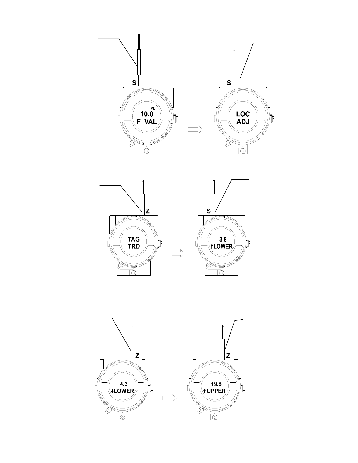
Local Adjustment
Remove it from opening S
Insert the magnetic tool in the
orifice Z. If it is the first option to
be configured, the option TAG
and its equivalent mnemonic will
be displayed. Otherwise, the last
option configured will be
displayed. By keeping the tool in
the opening, the loc al adjustment
menu will rotate through the
options on the local adjustment
tree.
Insert it again on
opening S. The
abbreviations LOC
ADJ will be displayed
Figure 8.4 – FI302 Step 2
The first option on the tree is
LOWER, with an arrow pointing
upwards. An arrow pointing
upwards () increments the
value and an arrow pointing
downwards () decrements the
value. This parameter is used to
calibrate the lower current
value. In order to adjust the
lower current value insert the
tool in orifice S. Leave it there
until the display shows 4,00 mA.
If the values are different, move
to FEED parameter and insert
the mili-amperimeter current
value to correct it.
In order to decrement the
lower value, insert the
magnetic tool in the orifice
Z to shift the arrow to the
downward position. Insert
the tool in opening S and
wait for the lower value to
decrement to 4,99 mA.
Insert the miliamperimeter
in the terminal block
output and measure the
current. If the values are
different, move to the
FEED parameter and
insert the miliamperimeter
current value to correct it.
Figure 8.5 – FI302 step 3
The UPPER option is used to
calibrate the upper current
value. Insert the magnetic tool
in the S and leave it there until
the display indicates 20,00
mA. Insert the miliamperimeter
in the output terminal of the
terminal block and measure
the current. If the values are
different, move to the FEED
parameter and insert the
current value read on the
meter to correct it.
Figure 8.6 – F302 Step 4
8.3
Page 49
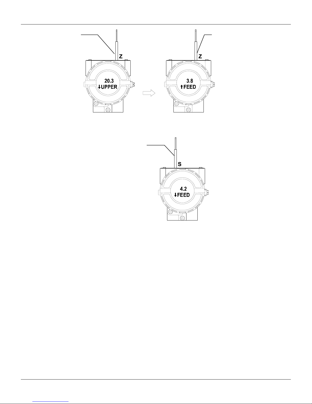
FI302 - Operation and Maintenance Instruction Manual
In order to decrement the
upper value, insert the
magnetic tool in the Z to
shift the arrow to the
downward position. Insert
the tool in the S and wait
for the lower value to
decrease to 20,00 mA.
Insert the miliamperimeter
in the output terminal of
theterminal block and
measure the current. If the
values are different, go to
the FEED parameter and
insert the miliamperimeter
current value to correct it.
Insert the magnetic tool in
the S to shift the arrow
downwards and decrement
the calibration current
according to the measured
value. An arrow pointing
downwards ()
willDecrement the current
value.
The FEED option allows the
user to correct the current
shown on the display, when
the current is different from
the standard value
measured at the output. To
implement the correction,
read the current shown on
the meter and apply this
value. This option makes it
possible to correct the
calibration points on both
Upper and Lower currents.
An arrow pointing upwards
() increments the curre nt.
Figure 8.7 – FI302 Step 5
Figure 8.8 – FI302 Step 6
8.4
Page 50

Section 9
TECHNICAL CHARACTERISTICS
Output Signal
Input Signal
Output Load Limitation
Power Supply
Output Impedance
Display
Hazardous Area Certification
Temperature Limits
Humidity Limits
Operation starting time
Update time
Accuracy
Ambient Temperature Effect
Output Power Supply Effect
Vibration Effect
Electromagnetic interference Effect
Electrical connection
Material of Construction
Mounting
Weight
Functional Specification
Three 4 - 20 mA current output, external supply, common ground.
F
OUNDATION™ fieldbus, digital, voltage mode 31.25 Kbit/s with bus power.
External 3 - 45 Vdc output supply.
Bus power 9 a 32 Vdc.
Quiescent current consumption 12 mA.
Non-intrinsic safety: 7.8 KH
intrinsic safety, the output impedance should be greater or equal to 400 , on the assumption
that exists a power supply barrier of 7.8 KHz to 39KHz.
4½ digit LCD display.
Explosion-proof and intrinsically safe (ATEX (NEMKO and DEKRA EXAM), FM, CEPEL, CSA
and NEPSI).
Designed to comply with European Regulations (ATEX 94/9/EC and LVD 2006/95/EC).
Operation: -40 to 85
Storage -40 to
Display: -10 to 60
-40 to 85
0 a 100% RH.
Approximately 10 seconds.
Approximately 0.2 seconds.
Performance Specification
0.1%.
For a 10º C variation: ± 0.05% .
± 0.005% V.
Complies with SAMA PMC 31.1.
Designed to comply with European Directive EMC 2004/108/EC.
Physical Specification
1/2 -14 NPT, PG 13.5 or M20 x 1.5.
Injected low copper aluminum and finishing with polyester painting or 316 stainless steel, with
Buna N O-rings on cover.
With an optional bracket, may be installed on a 2” pipe or on a wall or panel.
Without display and mounting brackets: 0.80 Kg.
Add 0.13 Kg for digital display.
Add 0.60 Kg for mounting bracket.
Z to 39 KHZ impedance must greater or equal to 3 K
o
C (-40 to 185 °F);
20 oC (-40 to 250 °F);
o
C ( 14 to 140 °F) Operation;
o
C (-40 to 185 °F) without damage.
. With an
9.1
Page 51
FI302 - Operation and Maintenance Instruction Manual
Ordering Code
MODEL
FI302 TRIPLE CHANNEL FOUNDATION FIELDBUS TO CURRENT CONVERTER
COD. Local Indicator
0 Without Indicator
1 With Digital Indicator
COD. Mounting Bracket
0 Without Bracket
1 Carbon Steel. Accessories: Carbon Steel
2 316 Stainless Steel. Accessories: AI316
7 Carbon Steel. Accessories: AI316
COD. Electrical Connections
0 1/2 - 14 NPT
1 1/2"- 14 NPT X 3/4 NPT (AI316) - with adapter
2 1/2" - 14 NPT X 3/4 BSP ( AI316) - with adapter
3 1/2" - 14 NPT X 1/2 BSP (AI316) - with adapter
A M20 X 1.5
B PG 13.5 DIN
SPECIAL OPTIONS
COD. Housing
H0 Aluminum (IP/TYPE)
H1 316 Stainless Steel (IP/TYPE)
H2 Aluminum for saline atmosphere (IPW/TYPE X)
H3 316 Stainless Steel for saline atmosphere (IPW/TYPE X)
COD. Identification Plate
I1 FM: XP, IS, NI, DI
I3 CSA: XP, IS, NI, DI
I4 EXAM (DMT): Ex-ia; NEMKO: Ex-d
I5 CEPEL: Ex-d, Ex-ia
I6 Without Certification
IE NEPSI: Ex-ia
COD. Painting
P0 Gray Munsell N 6,5 Polyester
P3 Black Polyester
P4 White Epoxi
P5 Yellow Polyester
P8 Without Painting
P9 Safety Blue Epoxy - Electrostatic Painting
PC Safety Blue Polyester - Electrostatic Painting
PG Safety Orange Epoxi Paint - Electrostatic Painting
COD. Tag Plate
COD. Special
FI302 1 1 0 * * * * * *
* Leave it blank if not applicable
COD. Output Signal
T0 3 output - 4 to 20 mA
J0 With tag
J1 Blank
J2 According to user’s notes
ZZ See Notes
TYPICAL MODEL
9.2
Page 52

Crrgpfkz"C"
CERTIFICATIONS INFORMATION
Gwtqrgcp"Fktgevkxg"Kphqtocvkqp"
Consult www.smar.com for the EC declarations of conformity for all applicable European directives
and certificates.
ATEX Directive (94/9/EC) – “Electrical equipment and protective system intended for use in
potential explosive atmospheres”
The EC-Type Examination Certificate had been released by Nemko AS (CE0470) and/or DEKRA
EXAM GmbH (CE0158), according to European Standards.
The certification body for Production Quality Assurance Notification (QAN) and IECEx Quality
Assessment Report (QAR) is Nemko AS (CE0470).
LVD Directive 2006/95/EC – “Electrical Equipment designed for use within certain voltage
limits”
According the LVD directive Annex II, electrical equipment for use in an explosive atmosphere is
outside the scope of this directive.
According to IEC standard: IEC 61010-1:2010 - Safety requirements for electrical equipment for
measurement, control, and laboratory use - Part 1: General requirements.
"
EMC Directive 2004/108/EC - “Electromagnetic Compatibility”
The equipment is in compliance with the directive and EMC test was performed according to IEC
standards: IEC61326-1:2005 and IEC61326-2-3:2006.
To comply with the EMC directive the installation must follow these special conditions:
Use shielded, twisted-pair cable for powering the instrument and signal wiring.
Keep the shield insulated at the instrument side, connecting the other one to the ground.
Jc|ctfqwu"Nqecvkqpu"Igpgtcn"Kphqtocvkqp"
Ex Standards:
IEC 60079-0 General Requirements
IEC 60079-1 Flameproof Enclosures “d”
IEC 60079-11 Intrinsic Safety “i”
IEC 60079-26 Equipment with equipment protection level (EPL) Ga
IEC 60529 Classification of degrees of protection provided by enclosures (IP Code)
Customer responsibility:
IEC 60079-10 Classification of Hazardous Areas
IEC 60079-14 Electrical installation design, selection and erection
IEC 60079-17 Electrical Installations, Inspections and Maintenance
Warning:
Explosions could result in death or serious injury, besides financial damage.
Installation of this instrument in an explosive environment must be in accordance with the national
standards and according to the local environmental protection method. Before proceeding with the
installation match the certificate parameters according to the environmental classification.
General Notes:
Maintenance and Repair
The instrument modification or replaced parts supplied by any other supplier than authorized
representative of Smar Equipamentos Industriais Ltda is prohibited and will void the Certification.
Marking Label
Once a device labeled with multiple approval types is installed, do not reinstall it using any other
approval types. Scratch off or mark unused approval types on the approval label.
For Ex-i protection application
- Connect the instrument to a proper intrinsically safe barrier.
C03
Page 53

HK524"⁄"Qrgtcvkqp"cpf"Ockpvgpcpeg"Kpuvtwevkqp"Ocpwcn"
- Check the intrinsically safe parameters involving the barrier, equipment including the cable and
connections.
- Associated apparatus ground bus shall be insulated from panels and mounting enclosures.
- When using shielded cable, isolate the not grounded cable end.
- Cable capacitance and inductance plus Ci and Li must be smaller than Co and Lo of the Associated
Apparatus.
For Ex-d protection application
- Only use Explosion Proof/Flameproof certified Plugs, Adapters and Cable glands.
- In an Explosion-Proof/Flame-Proof installation, do not remove the instrument housing covers when
powered on.
- Electrical Connection
In Explosion-Proof installations the cable entries must be connected through conduit with sealed
unit or closed using metal cable gland or closed using metal blanking plug, all with at least IP66
and Ex-d certification. For enclosure with saline environment protection (W) and ingress protection
(IP) applications, all NPT thread parts must apply a proper water-proof sealant (a non-hardening
silicone group sealant is recommended).
For Ex-d and Ex-i protection application
- The transmitter has a double protection. In this case the transmitter shall be fitted with appropriate
certified cable entries Ex-d and the electric circuit supplied by a certified diode safety barrier as
specified for the protection Ex-ia.
Environmental Protection
- Enclosure Types (Type X): Supplementary letter X meaning special condition defined as default by
Smar the following: Saline Environment approved - salt spray exposed for 200 hours at 35ºC. (Ref:
NEMA 250).
- Ingress protection (IP W): Supplementary letter W meaning special condition defined as default by
Smar the following: Saline Environment approved - salt spray exposed for 200 hours at 35ºC. (Ref:
IEC60529).
- Ingress protection (IP x8): Second numeral meaning continuous immersion in water under special
condition defined as default by Smar the following: 1 Bar pressure during 24hours. (Ref: IEC60529).
Jc|ctfqwu"Nqecvkqpu"Crrtqxcnu"
CSA (Canadian Standards Association)
Class 2258 02 – Process Control Equipment – For Hazardous Locations (CSA1002882)
Class I, Division 1, Groups B, C and D
Class II, Division 1, Groups E, F and G
Class III, Division 1
Class I, Division 2, Groups A, B, C and D
Class II, Division 2, Groups E, F and G
Class III
CLASS 2258 03 - Process Control Equipment – Intrinsically Safe and Non-Incendive Systems - For Hazardous Locations
(CSA 1002882)
Class I, Division 2, Groups A, B, C and D
Model FI302 Converter; supply 12-42V dc, 4-20mA; Enclosure Type 4/4X; non-incendive with Fieldbus / FNICO Entity
parameters
@ Terminals + and - :
Vmax =24V, Imax =570 mA, Pmax = 9.98 W, Ci = 5 nF, Li = 12uH;
@ Terminals 1 - 4:
Vmax =30V, Imax =110mA, Ci = 5 nF, Li = 12uH;
when connected through CSA Certified Safety Barriers as per SMAR Installation drawing 102A0559; Temp. Code T3C.
Class 2258 04 – Process Control Equipment – Intrinsically Safe Entity – For Hazardous Locations (CSA 1002882)
Class I, Division 1, Groups A, B, C and D
Class II, Division 1, Groups E, F and G
Class III, Division 1
FISCO Field Device
Model FI302 Converter; supply 12-42V dc, 4-20mA; Enclosure Type 4/4X; Intrinsically safe with Fieldbus/FISCO Entity
parameters
C04"
Page 54

Egtvkhkecvkqpu"Kphqtocvkqp"
@ Terminals + and -:
Vmax = 24 V, Imax = 380 mA, Pi = 5.32 W, Ci = 5 nF, Li = 12 uH;
@ Terminals 1 – 4:
Vmax = 30 V, Imax = 110 mA, Ci = 5nF, Li = 12 u H;
when connected through CSA Certified Safety Barriers as per Smar Installation Drawing: 102A0559; Code T3C.
Note: Only models with stainless steel external fittings are Certified as Type 4X.
Special conditions for safe use:
Temperature Class T3C
Maximum Ambient Temperature: 40ºC (-20 to 40 ºC)
FM Approvals (Factory Mutual)
Intrinsic Safety (FM 0D7A9.AX)
IS Class I, Division 1, Groups A, B, C and D
IS Class II, Division 1, Groups E, F and G
IS Class III, Division 1
Explosion Proof (FM 0D7A9.AX)
XP Class I, Division 1, Groups A, B, C and D
Dust Ignition Proof (FM 0D7A9.AX)
DIP Class II, Division 1, Groups E, F and G
DIP Class III, Division 1
Non Incendive (FM 0D7A9.AX)
NI Class I, Division 2, Groups A, B, C and D
Environmental Protection (FM 0D7A9.AX)
Option: Type 4X/6/6P or Type 4/6/6P
Special conditions for safe use:
Entity Parameters Fieldbus Power Supply Input (report 3015629):
Vmax = 24 Vdc, Imax = 250 mA, Pi = 1.2 W, Ci = 5 nF, Li = 12 uH
Vmax = 16 Vdc, Imax = 250 mA, Pi = 2 W, Ci = 5 nF, Li = 12 uH
4-20 mA Current Loop:
Vmax = 30 Vdc, Imax = 110 mA, Pi = 0,825 W, Ci = 5 nF, Li = 12 uH
Temperature Class T4
Maximum Ambient Temperature: 60ºC (-20 to 60 ºC)
NEMKO (Norges Elektriske MaterielKontroll)
Explosion Proof (NEMKO 13 ATEX 1570X)
Group II, Category 2 G, Ex d, Group IIC, Temperature Class T6, EPL Gb
Ambient Temperature: -20 ºC to +60 ºC
Environmental Protection (NEMKO 03ATEX1570X)
Options: IP66/68W or IP66/68
Special conditions for safe use:
Repairs of the flameproof joints must be made in compliance with the structural specifications provided by the manufacturer.
Repairs must not be made on the basis of values specified in tables 1 and 2 of EN/IEC 60079-1.
The Essential Health and Safety Requirements are assured by compliance with:
EN 60079-0:2012 General Requirements
EN 60079-1:2007 Flameproof Enclosures “d”
EXAM (BBG Prüf - und Zertifizier GmbH)
Intrinsic Safety (DMT 00 ATEX E 065)
Group I, Category M2, Ex ia, Group I, EPL Mb
C05"
Page 55

HK524"⁄"Qrgtcvkqp"cpf"Ockpvgpcpeg"Kpuvtwevkqp"Ocpwcn"
Group II, Category 2 G, Ex ia, Group IIC, Temperature Class T4/T5/T6, EPL Gb
FISCO Field Device
Supply circuit for the connection to an intrinsically safe FISCO fieldbus-circuit:
Ui = 24Vdc, Ii = 380 mA, Pi = 5.32 W, Ci ≤ 5 nF, Li = neg
Parameters of the supply circuit comply with FISCO model according to Annex G EN 60079-11:2012, replacing EN 60079-27:
2008.
Output-signal-circuits:
three 4-20 mA current sinks with common ground for external intrinsically safe supply
Effective internal capacitance Ci ≤ 15 nF
Effective internal inductance Li negligible
Safety-relevant maximum values for certified intrinsically safe 4-20 mA current loop circuits as a function of ambient temperature
and temperature class
Max. Ambient
temperature Ta
60ºC T4 28 V 93 mA 750 mW
50ºC T5 28 V 93 mA 750 mW
40ºC T6 28 V 93 mA 570 mW
The signal outputs are safely galvanically separated from the fieldbus circuit.
Ambient Temperature: -40ºC ≤ Ta ≤ +60ºC
The Essential Health and Safety Requirements are assured by compliance with:
EN 60079-0:2009 + A11:2013 General Requirements
EN 60079-11:2012 Intrinsic Safety “i”
CEPEL (Centro de Pesquisa de Energia Elétrica)
Intrinsic Safety (CEPEL 97.0019X)
Ex ia, Group IIC, Temperature Class T4/T5, EPL Ga
FISCO Field Device
Entity Parameters:
Pi = 5.32 W, Ui = 30V, Ii = 380 mA, Ci = 5.0 nF, Li = Neg
Ambient Temperature:
-20 to 65ºC for T4
-20 to 50ºC for T5
Explosion Proof (CEPEL 97.0091)
Ex d, Group IIC, Temperature Class T6, EPL Gb
Maximum Ambient Temperature: 40ºC (-20 to 40 ºC)
Environmental Protection (CEPEL 97.0019X AND CEPEL 97.0091)
Options: IP66/68W or IP66/68
Special conditions for safe use:
The certificate number ends with the letter "X" to indicate that for the version of FIELDBUS to current Converter model FI302
equipped with housing made of aluminum alloy, only can be installed in "Zone 0" if is excluded the risk of occurs impact or friction
between the housing and iron/steel itens.
The Essential Health and Safety Requirements are assured by compliance with:
ABNT NBR IEC 60079-0:2008 General Requirements
ABNT NBR IEC 60079-1:2009 Flameproof Enclosures “d”
ABNT NBR IEC 60079-11:2009 Intrinsic Safety “i”
ABNT NBR IEC 60079-26:2008 Equipment with equipment protection level (EPL) Ga
IEC 60079-27:2008 Fieldbus intrinsically safe concept (FISCO)
ABNT NBR IEC 60529:2009 Classification of degrees of protection provided by enclosures (IP Code)
Temperature
Class
Voltage DC
Ui
Current
Ii
Power
Pi
C06"
Page 56
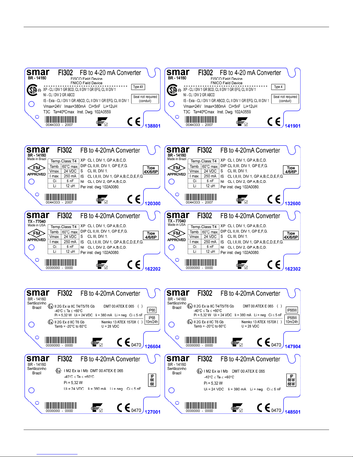
Egtvkhkecvkqpu"Kphqtocvkqp"
Kfgpvkhkecvkqp"Rncvg"cpf"Eqpvtqn"Ftcykpi"
CSA (Canadian Standards Association)
FM Approvals (Factory Mutual)
NEMKO (Norges Elektriske MaterielKontroll) / EXAM (BBG Prüf - und Zertifizier GmbH)
C07"
Page 57
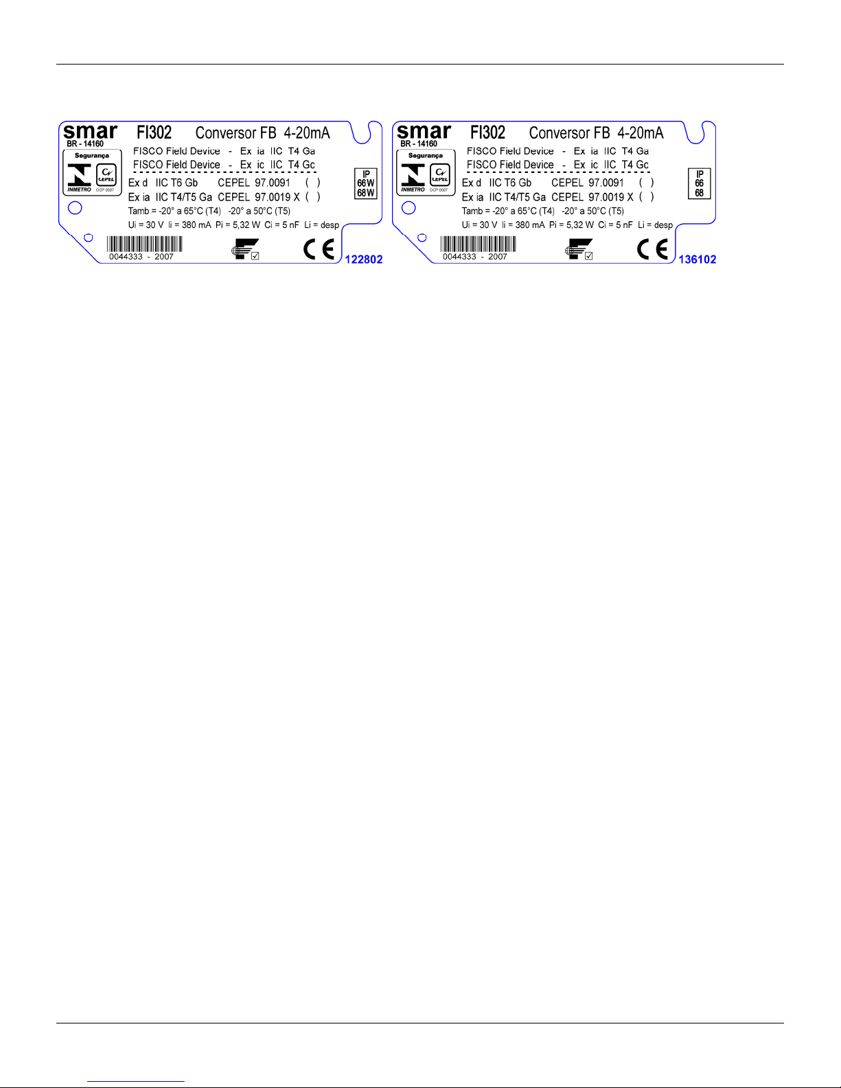
HK524"⁄"Qrgtcvkqp"cpf"Ockpvgpcpeg"Kpuvtwevkqp"Ocpwcn"
CEPEL (Centro de Pesquisa de Energia Elétrica)
C08"
Page 58
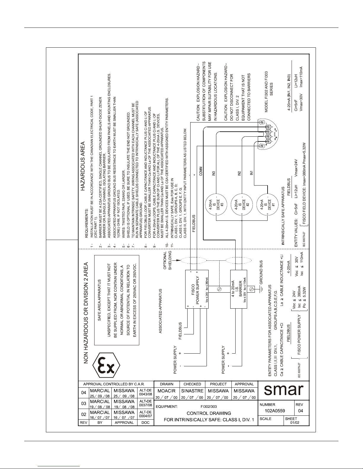
Egtvkhkecvkqpu"Kphqtocvkqp"
Canadian Standards Association (CSA)
C09"
Page 59
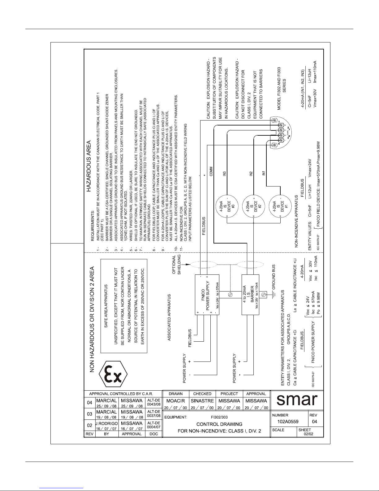
HK524"⁄"Qrgtcvkqp"cpf"Ockpvgpcpeg"Kpuvtwevkqp"Ocpwcn"
C0:"
Page 60
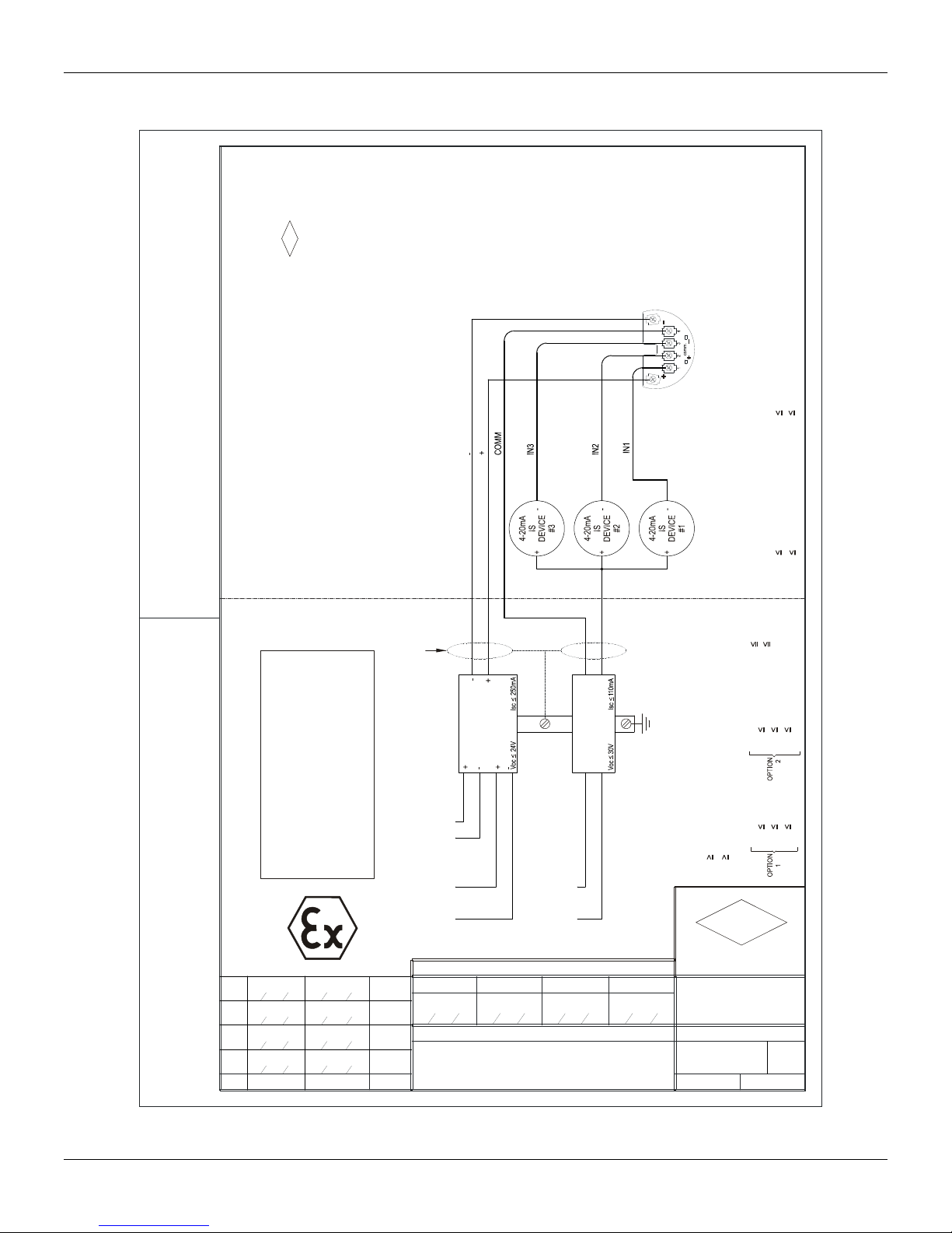
Egtvkhkecvkqpu"Kphqtocvkqp"
Factory Mutual (FM)
HAZARDOUS AREA
COMPONENTS CAN NOT
BE SUBSTITUTED WITHOUT
PREVIOUS MANUFACTURER
APPROVAL.
110 mA
30V
Imax
4-20mA
Vmax
Ci=5nF Li=12uH
REQUIREMENTS:
1 - INSTALLATION MUST BE IN ACCORDANCE WITH THE NATIONAL ELECTRICAL CODE
APPROVAL LISTING.
2 -
3 - ASSOCIATED APPARATUS GROUND BUS TO BE INSULATED FROM PANELS
SAFE AREA APPARATUS
UNSPECIFIED, EXCEPT THAT IT MUST NOT
BE SUPPLIED FROM, NOR CONTAIN UNDER
TRANSMITTER SPECIFICATION MUST BE IN ACCORDANCE TO FM
(ANSI/NFPA 70) AND ANSI/ISA-RP12.6
NON HAZARDOUS OR DIVISION 2 AREA
MARCIAL
7
20
MARCIAL
6
16
MOACIR
5
07
MOACIR
4
REV.
DESIGN AREA
10 08
07 07
05 03
MISSAWA
20 10 08
MISSAWA
16 07 07
CASSIOLATO
07 05 03
CASSIOLATO
08
250mA
24V
SHIELD IS OPTIONAL IF USED, BE SURE TO INSULATE THE END NOT
AND MOUNTING ENCLOSURES.
NORMAL OR ABNORMAL CONDITIONS, A
WIRES: TWISTED PAIR, 22AWG OR LARGER.
SMALLER THAN 1(ONE) OHM, IF NOT ISOLATED.
4 - ASSOCIATED APPARATUS GROUND BUS RESISTANCE TO EARTH MUST BE
SOURCE OF POTENTIAL IN RELATION TO
EARTH IN EXCESS OF 250VAC OR 250VDC.
0002000208
GROUNDED.
CABLE CAPACITANCE AND INDUTANCE PLUS Ci AND Li MUST BE
SMALLER THAN Ca AND La OF THE ASSOCIATED APPARATUS.
5 -
6 -
7 -
FIELDBUS
OPTIONAL
SHIELDING
I.S.
BARRIER
FIELDBUS
FIELDBUS
+-
POWER SUPPLY
APPROVAL CONTROLLED BY C.A.R.
DRAWING DESIGN VERIFIED APPROVED
MELONI
28 03 95 28 03 95 28 03 95 28 03 95
CUSTOMER:
EQUIPMENT: FI302/303
M.MISSAWA
+-
POWER SUPPLY
CONTROL DRAWING
ALT DE
0049/08
ALT DE
0004/07
ALT DE
0043/03
ALT DE
0015/00
ASSOCIATED APPARATUS
I.S.
4 to 20mA
BARRIER
FIELDBUS
Imax
Ci=5nF Li=12uH
Vmax
30V
110mA
Isc
Voc
250mA
Po
Isc
Voc 16V
24V
1,2W
250mAIsc
Po 2W
Voc
CLASS I,II,III DIV.1, GROUPS A,B,C,D,E,F & G
MODELS FI302 AND FI303 - SERIES
ENTITY VALUES:
4-20mA
GROUND BUS
FIELDBUS
La CABLE INDUCTANCE +12uh
Ca CABLE CAPACITANCE +5nF
GROUPS A,B,C,D,E,F & G
ENTITY PARAMETERS FOR ASSOCIATED APPARATUS
CLASS I,II,III DIV.1
FM
APPROVED
PELUSOSINASTRE
smar
O.S.
DRAWING N.
102A0080
: SH.
REV
07
01/01APPROVED
C0;"
Page 61

HK524"⁄"Qrgtcvkqp"cpf"Ockpvgpcpeg"Kpuvtwevkqp"Ocpwcn"
C032"
Page 62

Appendix B
Model: FI302 ( ) FI303 ( )
Serial Number:
TAG:
How many
channels are
used in IF?
Configuration: Magnetic Tool ( ) PC ( ) Software: _____________ Version: ________________ Other: _____________________
Type/Model/Manufacturer of device
connected to the channel 1:
Type/Model/Manufacturer of device
connected to the channel
Type/Model/Manufacturer of device
connected to the channel
Hazardous Area
Classification:
( ) No
More details: _______________________________________________________________________________________
Types of Interference
presents in the area:
Ambient
Temperature:
_____________________________________________________________________________________________________________________
______________________________________________________________________________________________________
______________________________________________________________________________________________________
1 ( ) 2 ( ) 3 ( )
_____________________________________________________________________________________
2: _____________________________________________________________________________________
3: _____________________________________________________________________________________
( ) Yes, please specify: ______________________________________________________________________________
Without interference ( ) Temperature ( ) Vibration ( ) Others: ____________________________________
From __________ºC up to __________ºC
SRF – Service Request Form
Converter from Fieldbus to 4-20mA
GENERAL DATA
INSTALLATION DATA
PROCESS DATA
OCCURRENCE DESCRIPTION
_____________________________________________________________________________________________________________________
_____________________________________________________________________________________________________________________
SERVICE SUGGESTION
Adjustment ( ) Cleaning ( ) Preventive Maintenance ( ) Update / Up-grade ( )
Other: ___________________________________________________________ ____________________________________________________
USER INFORMATION
Company: ___________________________________________________________________________________________________________
Contact: _____________________________________________________________________________________________________________
Title: ________________________________________________________________________________________________________________
Section: _____________________________________________________________________________________________________________
Phone: _________ _________________________ _________ _________________________ Extension: __________________________
E-mail: ________________________________________________________________________ Date: ______/ ______/ _________________
Further information about address and contacts can be found on www.smar.com/contactus.asp.
For warranty or non-warranty repair, please contact your representative.
B.1
Page 63

FI302 – Operation, Maintenance and Instructions Manual
Returning Materials
Should it be necessary to return the converter to Smar, simply contact your local Smar office
informing the defective equipment serial number and dispatch it to our factory.
For easier analysis and faster solution of the problem, the returned material should include the
documentation with a description of the failure observed in the field and the circumstances that
caused it. Other information, such as the installation site, type of measure taken and the proces s
conditions are also important for a prompt evaluation.
B.2
 Loading...