

Page 1
USER MANUAL
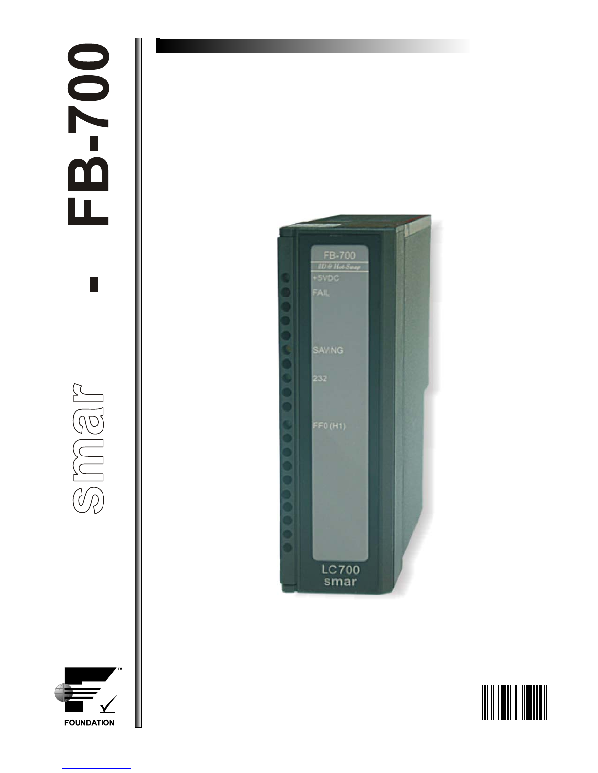
FB-700 - Fieldbus Module
APR / 08
FB700ME
Page 2

r
sma
Specifications and information are subject to change without notice.
Up-to-date address information is available on our website.
web: www.smar.c om/contactus.asp
www.smar.com
Page 3
Introduction
ATTENTION
From the serial number SN1249 of the FB700 module, SerialDownload (software to download the
firmware) version V3.4.0.0 or higher and firmware version V3.46J or higher is necessary.
The software and firmware compatible with the new version of the module are availabl e from System302
V7.0.6. For previous versions of System302, the upgrade for SerialDownload and firmware can be
downloaded from the FB700 page at the Smar website (www.smar.com.br).
WARNING
The previous versions from firmware 3.46J may be do wnloaded to the module (with the SerialDownload
software version above), but the characteristics of saving non-volatile data durin g the shutdown will be
lost. (Non-volatile data are dynamic data saved duri ng the power down, such as th e OUT parameter from
the Integrator block, or SP, OUT and BKCAL_IN parameters from the PID block). For more information
refer to the Function Blocks User’s Manual.
3
Page 4

FB-700 – User’s Manual
4
Page 5
Description
FB-700 – Fieldbus Module
FB-700 – Fieldbus Module
(Supports Hot swap and Device ID)
Part Number:
FB-700 - Fieldbus Module
The FB-700 is a Fieldbus interface card for the LC700 programmable controller. It integrates the
discrete control capability of LC700 with Fieldbus.
The Foundation™ Fieldbus interoperability feature assures that the FB-700 will work perfectly with
any other FF device, even from manufacturers other than Smar.
The FB-700 is directly attached to the LC700 backplane. The LC700 accesses it as a regular I/O
card, which supports many digital and analog I/O points mapped to the FB-700 function blocks. For
proper operation, both CONF700 and SYSCON should configure the card.
Function Blocks
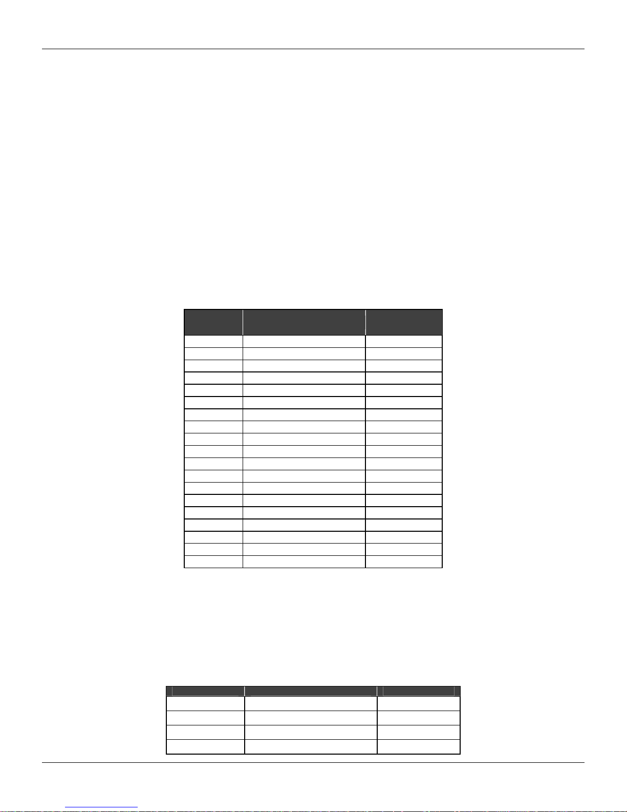
FB-700 can execute the following function blocks, some of which are pre-instantiated:
Block Type Description
RS Resource 1
DIAG Diagnostics Transducer 1
MAI Multiple Analogic Inputs 2
MDI Multiple Discrete Inputs 3
PID PID Control 1
EPID Enhanced PID Control 0
ARTH Arithmetic 0
SPLT Split Range 0
CHAR Signal Characterizer 0
INTG Integrator 0
AALM Analogic Alarm 1
ISEL Input Selector 0
SPG Set point Ramp Generator 0
TIME Time and Logic 0
LLAG Lead-Lag 0
OSDL Output Selector/Dynamic Limiter 0
CT Constant 0
MAO Multiple Analogic Output 2
MDO Multiple Discrete Output 4
In the table above:
- Block Type: it means the available block types for the device
- Description: it shows the description of each block.
- Number of instantiations:
0 – this block type is not pre-instantiated in the FB-700.
1 to 4 – it indicates the quantity of pre-instantiated blocks in the FB-700.
There are blocks that have correlation with the LC700. These blocks are described below:
Block Type Description LC700 Block
MDI Multiple Discrete Inputs CODD
MDO Multiple Discrete Outputs CIDD
MAI Multiple Analogic Inputs COAD
MAO Multiple Analogic Outputs CIAD
Number of
Instantiations
5
Page 6
FB-700 – User’s Manual
Connecting FB-700 to LC700
Before connecting or disconnecting the FB-700 from the LC700 backplane, please b e sure that the
LC700 power is OFF.
LEDs behavior
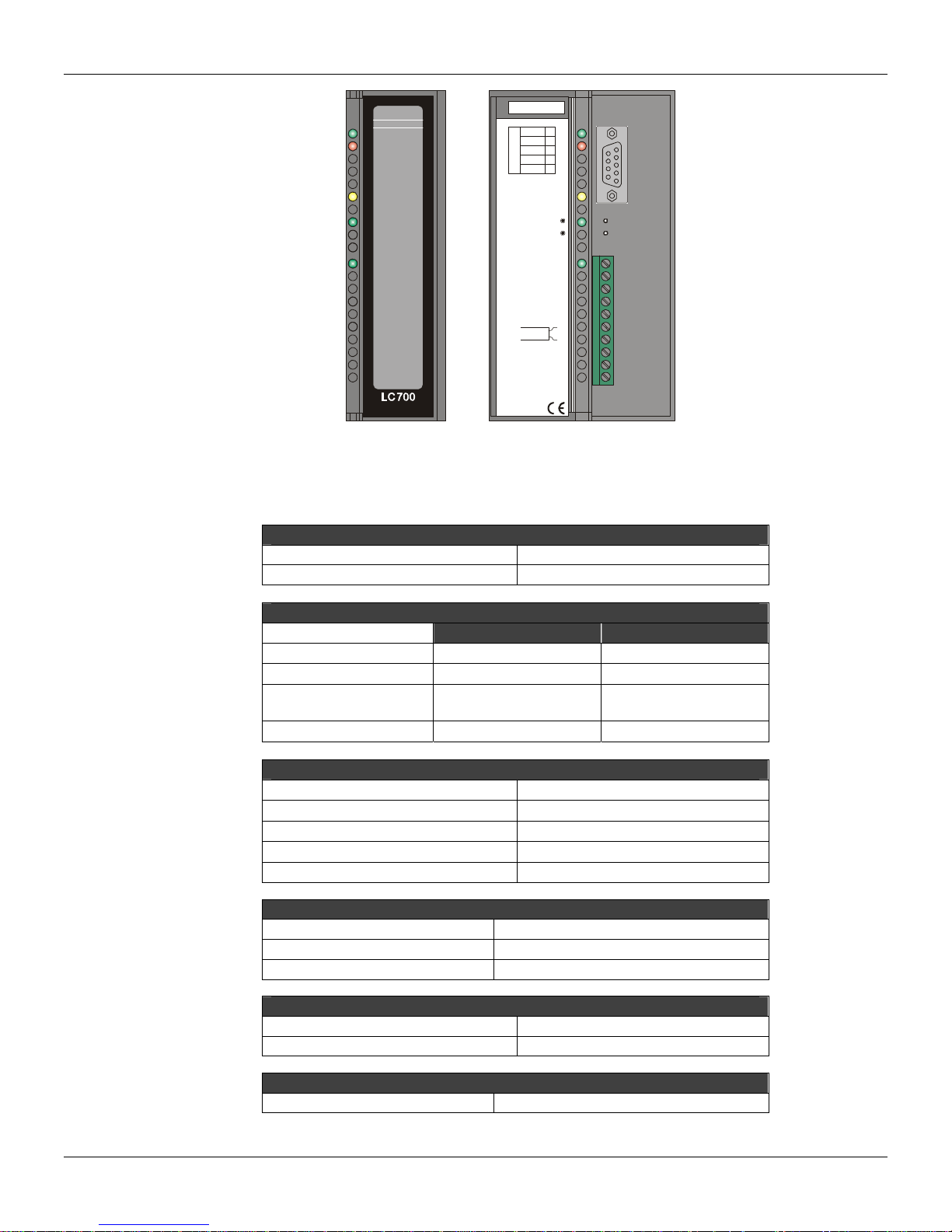
The FB-700 red and yellow LEDs indicate errors and warnings as describ ed in the following tables:
Yellow Led
Always on
Blinking at 1s
rate
Blinking at 3s
rate
Blinking at 5s
rate
Red Led
Always on
Blinking at 1s
rate
FB-700 is saving nonvolatile data. After finishing this operation
the yellow led will be turned off.
LC700 and FB-700 do not have the same configuration
parameters. Please, check both SYSCON and LC700
configurations to ensure that the number of function blocks and
FB700 TAG are the same.
There is a new configuration in the dual port memory, but the
LC700 does not check it.
There is a new configuration in the dual port memory without
any MIO function block.
A critical error happened and FB-700 is in a permanent
failure state. FB-700 must be reset.
LC700 is not accessing FB-700. Possible causes are LC700
is not running properly, FB-700 is not present in LC700
configuration or rack addressing is wrong.
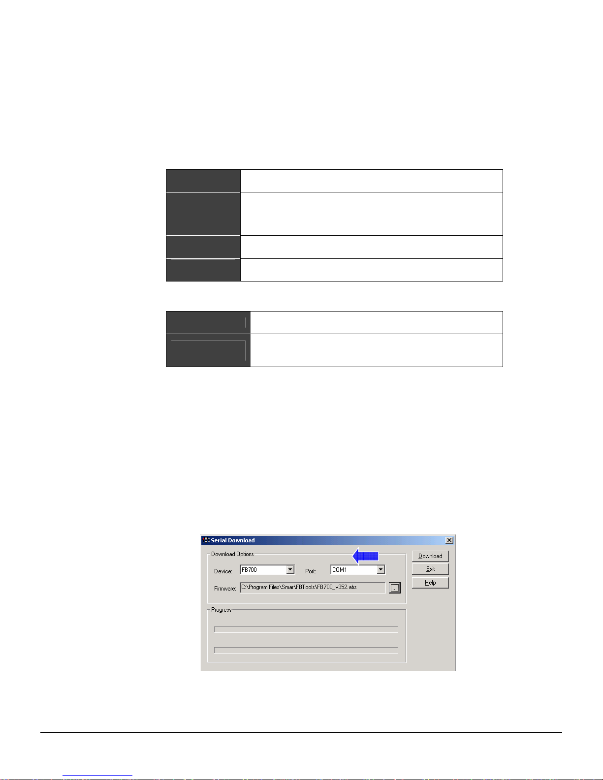
Firmware Version Changes and Updates
Using the “FBTOOLS” software, the user can change versions of the firmware in the Flash memor y.
The FB-700 Module has a DB-9 connector for this purpose.
Follow the steps below to update and/or change the firmware for the FB-700 module:
1. Choose a serial port.
2. Connect the C232-700 cable to the FB700 and the PC serial port chosen in item 1.
3. Press FB700 RESET button to force download mode. The RED led will turn on.
4. Select and open the file FB700.ABS.
5. Click on Download button to start the firmware download.
6. Disconnect the C232-700 cable.
7. Press RESET button again to reset the FB700. The RED led will turn off.
6
Page 7
FB-700 – Fieldbus Module
Notes:
1. Certify that no other application or resident program in the PC is using the I/O port or IRQ of the
selected serial port.
2. After resetting, the FB700 will automatically execute a factory initialization proced ure (yellow le d
will turn on), if necessary.
3. An LC700 system can have more than one FB module. The limit number of FB modules per
system is determined by the amount of the available configuration memory.
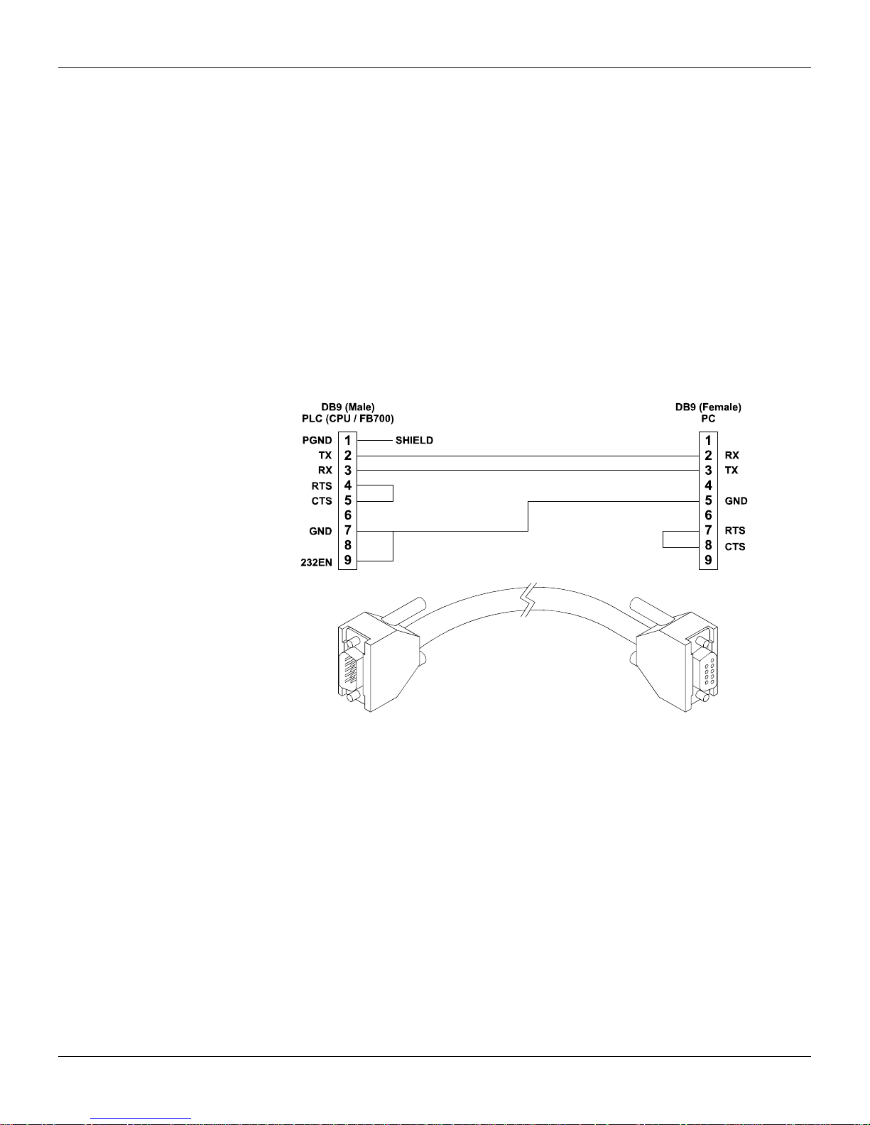
CABLE EIA-232 TO CONNECT FB-700
Part Number:
C232-700 – cable to connect FB-700 module to the PC
Description
This cable must be used in updating/changin g the firmware version in the internal flash memory of
the FB-700 module.
CABLE EIA-232 TO CONNECT FB-700
7
Page 8
FB-700 – User’s Manual
FB-700FB-700
ID & Hot-Swap
+5VDC+5VDC+5VDC+5VDC
FAILFAIL
SAVINGSAVING
232232
PGNDTX1
RX
RS-232
GND
5V
0,5A
FACTORY INIT
RESET
2
3
7
8
Technical Specifications
Type
Architecture
Code
Data
Retention
Dual-Port
Number of Channels 1 H1 channel (31,25 Kbps)
Controller FB3050 SMAR (DMA Integrated)
Physical Layer Standard
Fieldbus Interface
Intrinsic Safety
Supplied by the IMB bus 5 Vdc @ 110 mA
Total Maximum Dissipation 0.55 W
Source Indicator Green LED + 5 Vdc
Operation 0 to 60 ºC
Storage -20 to 80 ºC
IMB Communication Channel 500 Vac
FF0 (H1)FF0 (H1)
smar
Fieldbus Module FB-700
MEMORY
512 kB, 8-bit Flash Downloadable firmware
128 kB, 8-bit RAM Dynamic data
8 kB, 8-bit serial
EEPROM
32 kB, 8-bit DPRAM LC700 interface
FIELDBUS INTERFACE
INTERNAL SOURCE
TEMPERATURE
ISOLATION
1B
2B
3B
FF0 (H1)
4B
5B
6B
7B
8B
9B
10B
LC700/FB-700 Fieldbus Module
CPU
Low Power Microcontroller
8-bit CISC
Capacity Functionality
Configuration retention
ISA-S50.02-1992
Passive (not bus powered)
NOT compliant
8
Page 9
Dimensions (W x H x D)
Weight 0.261 kg
One wire 14 AWG (2 mm2)
Two wires 20 AWG (0.5 mm2)
Installing the Module in the Rack
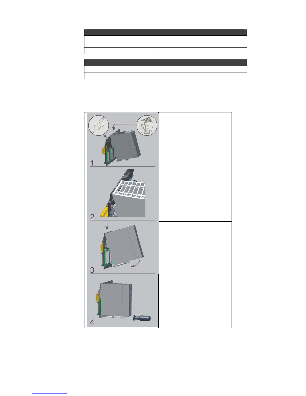
Follow the steps below to install the module in the rack.
FB-700 – Fieldbus Module
DIMENSIONS AND WEIGHT
39.9 x 137.0 x 141.5 mm
(1.57 x 5.39 x 5.57 in)
CABLES
Mounting a module in the rack:
o Find the border located
at the top of the free
slot.
o Fit the hole, at the top
back of the module.
Mounting detail.
Lock the module in the connector
(slot) of the IMB by pushing it
against the rack.
Next, fix the module at the rack
using a screw driver, and fix the
locking screw at the bottom of the
module.
9
Page 10

FB-700 – User’s Manual
10
Page 11
Appendix A
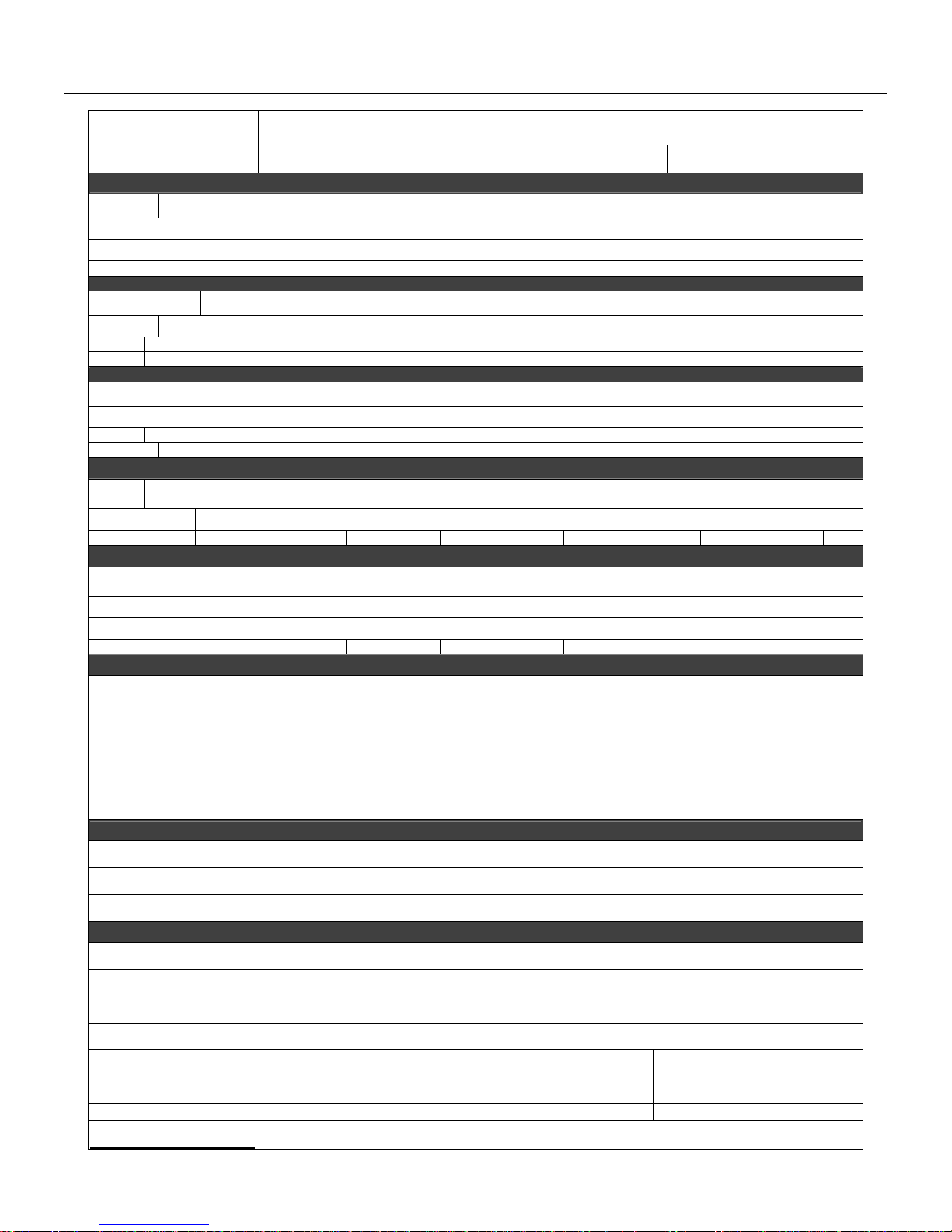
SRF – Service Request Form
smar
FB700 – Fieldbus Module
COMPANY INFORMATION
Company: __________________________________________________________________________ ___________________________
Unit/Department:___________ _______________________________________ ______________________________________________
Invoice:______________ ________________________________________________________________________________________
COMMERCIAL CONTACT
Full Name:______ __________________________________________________________________________ _____________________
Phone:___ _________ _________________________ _________ _________________________ Fax: _______________________
Email: __________________________________________________________________________ _____________________________
TECHNICAL CONTACT
Full Name: _____________________________________________________________________________________________________
Phone: _________ _________________________ _________ _________________________ Extension: _______________________
Email: __________________________________________________________________________ _____________________________
EQUIPMENT DATA
Model: __________________________________________________________________________ ____________________________
Serial Number: _______________________________________________________________________________________________
PROCESS DATA
Process Type: _________________________________________________________________________________________________
Operation Time: ________________________________________________________________________________________________
Failure Date: ___________________________________________________________________________________________________
FAILURE DESCRIPTION
(Please, describe the observed behavior, if it is repetitive, how it reproduces, etc.)
__________________________________________________________________________ ____________________________________
__________________________________________________________________________ ____________________________________
__________________________________________________________________________ ____________________________________
__________________________________________________________________________ ____________________________________
OBSERVATIONS
__________________________________________________________________________ ____________________________________
Proposal Nº:
__________________________________________________________________________ ____________________________________
__________________________________________________________________________ ____________________________________
Company: _____________________________________________________________________________________________________
Contact: ______________________________________________________________________________________________________
Title: _________________________________________________________________________________________________________
Section:_________________________________________________________________________________________________________
Phone: _________ _________________________ _________ _________________________ Extension: ___________________
E-mail: ________________________________________________________________________ Date: ______/ ______/ _________
For warranty or non-warranty repair, please contact your representative. Further information about address and contacts can be found on
www.smar.com/contactus.asp
.
USER INFORMATION
A.1
Page 12

FB-700 – User’s Manual
A.2
Page 13

Appendix B
SMAR WARRANTY CERTIF ICATE
1. SMAR guarantees its products for a period of 24 (twenty four) months, starting on the day of
issuance of the invoice. The guarantee is valid regardless of the day that the product was
installed.
2. SMAR products are guaranteed against any defect originating from manufacturing, mounting,
whether of a material or manpower nature, provided that the technical analysis reveals the
existence of a quality failure liable to be classified under the meaning of the word, duly verified
by the technical team within the warranty terms.
3. Exceptions are proven cases of inappropriate use, wrong handling or lack of basic maintenance
compliant to the equipment manual provisions. SMAR does not guarantee any defect or
damage caused by an uncontrolled situation, including but not limited to negligence, user
imprudence or negligence, natural forces, wars or civil unrest, accidents, inadequate
transportation or packaging due to the user’s responsibility, defects caused by fire, theft or stray
shipment, improper electric voltage or power source connection, electric surges, violations,
modifications not described on the instructions manual, and/or if the serial number was altered
or removed, substitution of parts, adjustments or repairs carried out by non-authorized
personnel; inappropriate product use and/or application that cause corrosion, risks or
deformation on the product, damages on parts or components, inadequate cleaning with
incompatible chemical products, solvent and abrasive products incompatible with construction
materials, chemical or electrolytic influences, parts and components susceptible to decay from
regular use, use of equipment beyond operational limits (temperature, humidity, etc.) according
to the instructions manual. In addition, this Warranty Certificate excludes expenses with
transportation, freight, insurance, all of which are the customer’s responsibility.
4. For warranty or non-warranty repair, please contact your representative.
Further information about address and contacts can be found on www.smar.com/contactus.asp
5. In cases needing technical assistance at the customer’s facilities during the warranty period,
the hours effectively worked will not be billed, although SMAR shall be reimbursed from the
service technician’s transportation, meals and lodging expenses, as well dismounting/mounting
costs, if any.
6. The repair and/or substitution of defective parts do not extend, under any circumstance, the
original warranty term, unless this extension is granted and communicated in writing by SMAR.
7. No Collaborator, Representative or any third party has the right, on SMAR’s behalf, to grant
warranty or assume some responsibility for SMAR products. If any warranty would be granted
or assumed without SMAR’s written consent, it will be declared void beforehand.
8. Cases of Extended Warranty acquisition must be negotiated with and documented by SMAR.
9. If necessary to return the equipment or product for repair or analysis, contact us.
See item 4.
10. In cases of repair or analysis, the customer must fill out the Revision Requisition Form (FSR)
included in the instructions manual, which contains details on the failure observed on the field,
the circumstances it occurred, in addition to information on the installation site and process
conditions. Equipments and products excluded from the warranty clauses must be approved by
the client prior to the service execution.
11. In cases of repairs, the client shall be responsible for the proper product packaging and SMAR
will not cover any damage occurred in shipment.
B.1
Page 14

FB-700 – User’s Manual
12. In cases of repairs under warranty, recall or outside warranty, the client is responsible for the
correct packaging and packing and SMAR shall not cover any damage caused during
transportation. Service expenses or any costs related to installing and uninstalling the product
are the client´s sole responsibility and SMAR does not assume any accountability before the
buyer.
13. It is the customer’s responsibility to clean and decontaminate products and accessories prior to
shipping them for repair, and SMAR and its dealer reserve themselves the right to refuse the
service in cases not compliant to those conditions. It is the customer’s responsibility to tell
SMAR and its dealer when the product was utilized in applications that contaminate the
equipment with harmful products during its handling and repair. Any other damages,
consequences, indemnity claims, expenses and other costs caused by the lack of
decontamination will be attributed to the client. Kindly, fill out the Declaration of
Decontamination prior to shipping products to SMAR or its dealers, which can be accessed at
www.smar.com/doc/declarationofcontamination.pdf
and include in the packaging.
14. This warranty certificate is valid only when accompanying the purchase invoice.
B.2
 Loading...