

Page 1
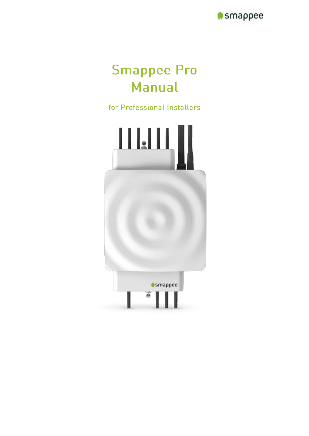
Smappee Pro Installation and Product Manual Page 1 of 74
Version 2.0.0, 24-09-2018, rev 102
English
Version 2.0.0
Date: 24-Sep-2018
© 2013-2018 Smappee NV. All rights reserved.
Specifications are subject to change without notice.
All product names are trademarks of their respective companies.
Page 2

Smappee Pro Installation and Product Manual Page 2 of 74
Version 2.0.0, 24-09-2018, rev 102
Page 3
Smappee Pro Installation and Product Manual Page 3 of 74
Version 2.0.0, 24-09-2018, rev 102
Table of Contents
Safety Instructions ......................................................................................................... 7
Safety Warning ............................................................................................................ 7
Safety precautions ...................................................................................................... 7
Product Identification ................................................................................................. 7
Specifications .............................................................................................................. 7
Explanation of symbols related to safety ................................................................... 8
Residual safety risk .................................................................................................... 8
Maintenance ............................................................................................................... 8
Support ....................................................................................................................... 8
Installation overview .......................................................................................................... 9
Smappee Pro components ........................................................................................... 10
Planning and site preparations for Smappee Pro installation ................................ ........ 11
Overview installation - Step-by-Step ............................................................................... 12
Step 1: Turn off Power .................................................................................................. 13
Step 2: Remove panel and Smappee covers ................................................................ 14
Accessing the Connectors ........................................................................................ 14
Connectors at the Front............................................................................................ 14
Connectors at the Back ............................................................................................ 14
Step 3: Mount Smappee Pro monitor ........................................................................... 15
Step 4: Connect the voltage measurement and power supply wiring ......................... 16
Installation Variants .................................................................................................. 17
Single-Phase ....................................................................................................................... 17
.............................................................. 19
Step 6: Plug in the internet connection ........................................................................ 23
Step 7: Verify and replace covers ................................................................................. 24
Step 8: Turn on Power .................................................................................................. 25
Colors of the Smappee Light .................................................................................... 26
Colors of 4G dongle .................................................................................................. 26
Wi-Fi connection details .................................................................................................. 27
Step 9: Smappee account creation and activation ....................................................... 28
Step 10: Smappee channel input configuration ........................................................... 30
Step 10.a: Configuration Expert Portal (Recommended) .......................................... 31
Step 10.b: Configuration Smappee app ..................................................................... 40
Step 11a: Final installation check-up Expert Portal (Recommended) ...................... 42
Step 11.b: Final installation check-up Smappee app ................................................ 45
Page 4
Smappee Pro Installation and Product Manual Page 4 of 74
Version 2.0.0, 24-09-2018, rev 102
Step 12 (Optional): Share Smappee with other Smappee user .................................... 46
How to install multiple Smappee monitors under 1 user account .............................. 47
Process ..................................................................................................................... 47
Smappee Product Manual ................................................................................................ 48
The connectors and Inputs of the Smappee .................................................................... 49
Overview.................................................................................................................... 49
Accessing the Connectors ........................................................................................ 49
Connectors at the Front............................................................................................ 49
Connectors at the Back ............................................................................................ 49
The Green 8-Pin Connector Block ............................................................................ 50
Connecting the Power Supply ...................................................................................... 51
Overview.................................................................................................................... 51
Connecting the wires ................................................................................................ 51
Important Requirements .......................................................................................... 51
Connecting the Voltage Measurement Wires .............................................................. 52
Overview! .................................................................................................................. 52
Separated Power Supply .......................................................................................... 52
Inputs for Phase and Neutral ................................................................................... 52
Installation Variants .................................................................................................. 52
Installation Variants .................................................................................................. 53
Verify the Correctness of Installation ....................................................................... 54
.............................................................. 55
Overview.................................................................................................................... 55
Configuration ............................................................................................................ 55
Technical details ....................................................................................................... 55
Instructions ............................................................................................................... 55
Rogowski Coils.......................................................................................................... 55
Current Transformer Variants ..................................................................................... 56
Preparing the Internet Connection .............................................................................. 58
Overview.................................................................................................................... 58
NO Hot-Plugging....................................................................................................... 58
Ethernet cable (recommended) ................................................................................ 58
External Wi-Fi module (USB) ................................................................................... 58
External 3G/4G Dongle (USB) ................................................................................... 58
Connect the cable or USB module ........................................................................... 58
Initial Power-On of the Smappee Monitor .................................................................... 59
Introduction .............................................................................................................. 59
Page 5
Smappee Pro Installation and Product Manual Page 5 of 74
Version 2.0.0, 24-09-2018, rev 102
Check Before First Power-On .................................................................................. 59
Power On .................................................................................................................. 59
Lights for Network Status ........................................................................................ 59
Working with Multiple Sites ......................................................................................... 60
Overview.................................................................................................................... 60
Important .................................................................................................................. 60
Understanding Service Locations ............................................................................. 60
Basic Principles ........................................................................................................ 60
Starting the Installation of a Replacement Device ................................................... 61
Troubleshooting Internet and Cloud Access ................................................................ 62
Introduction .............................................................................................................. 62
Understanding the milestones ................................................................................. 62
Issues with Local Network (Ethernet or Wi-Fi) ........................................................ 62
Wi-Fi Checklist ......................................................................................................... 62
Colors of the Smappee Light .................................................................................... 63
Colors of 4G dongle .................................................................................................. 63
Configure the Current Transformers ........................................................................... 64
Overview.................................................................................................................... 64
................................................................................ 64
Where to Modify the Configuration ........................................................................... 64
Configure the Smappee in the Expert Portal ............................................................... 65
Overview.................................................................................................................... 65
Expert Portal for Advanced Users ............................................................................ 65
Before you can Start ................................................................................................. 65
Connecting to the Expert Portal ............................................................................... 65
Login to the Expert Portal ........................................................................................ 65
Understanding the Menu Items ................................................................................ 66
Configuration menu .................................................................................................. 66
Channel Configuration menu ................................................................................... 66
Diagnose the Smappee in the Expert Portal ................................................................ 67
Overview.................................................................................................................... 67
Voltage Display per Phase ........................................................................................ 67
Real-Time Measurements ........................................................................................ 67
Details for Parameters ............................................................................................. 67
Connected Current Transformers ............................................................................ 68
Special Cases - Rogowski Coils ................................................................ ................... 69
Overview.................................................................................................................... 69
Page 6

Smappee Pro Installation and Product Manual Page 6 of 74
Version 2.0.0, 24-09-2018, rev 102
Checklist for Correct Configuration ............................................................................. 70
Overview.................................................................................................................... 70
Quick Check .............................................................................................................. 70
Checklist for Electrical Parameters ......................................................................... 70
Checklist for Total Measurements ........................................................................... 71
Troubleshooting ........................................................................................................ 71
Mounting and Enclosing ............................................................................................... 72
Overview.................................................................................................................... 72
Mounting ................................................................................................................... 72
Cover ......................................................................................................................... 72
Final Remarks .................................................................................................................. 73
Gain insights ............................................................................................................. 73
Support During Installation ...................................................................................... 73
Training ..................................................................................................................... 73
Feedback .................................................................................................................. 73
Appendix ........................................................................................................................... 74
Sample Configuration Table (3-Phase Star Config) ............................................................... 74
Configuration Table Template ............................................................................................ 74
Page 7

Smappee Pro Installation and Product Manual Page 7 of 74
Version 2.0.0, 24-09-2018, rev 102
Safety Instructions
Safety Warning
Working on your electrical installation can be dangerous.
The installation of the device must be done inside the distribution board under a
protective cover.
The installation must be performed according to the national safety regulations and
executed by a certified electrician.
Safety precautions
Please observe the following safety precautions in order to avoid potential electrical
shock, fire or personal injury:
• Do not use this Product for any purpose other than for which it was intended.
• Do not open the equipment or touch any of its electronic circuitry.
• Do not attempt to repair or service any part of the Smappee Pro.
• Only use the cables which were delivered with the Product.
• Do not use the Product if damaged.
• Do not use damaged current transformer or cables.
• Do not immerse the Product in water, or any other liquids.
• Do not expose the Product to heat, flame or extreme cold.
• The wires used for the voltage connection must have an insulation suitable for the
connected voltages, with sections from 0.75 and 2.5mm².
• The tightening torque must be between 0.5 and 0.6 Nm.
Product Identification
• Product Article Number: monitor-e2
Specifications
• Dimensions: 180x130x35mm (7x5.1x1.38 in)
• Weight: 300g (10.6 oz)
• Operating temperature: -10 - +50°C (14 - 122 °F)
• Storage temperature: -20 - +70°C (-4 - 158 °F)
• Relative humidity: 80% at 0 - +50°C (32 - 104 °F)
• Operating altitude: 0 2.000 m (0 - 6561 ft)
• EMC: EN 55022 (Class B)
• Safety: conforms to UL/IEC/EN 61010-1 Ed3 2010, CAT II
• Power supply: 100 240 Vrms / 50..60 Hz
• Inputs: Ph1,Ph2,Ph3,N
Page 8
Smappee Pro Installation and Product Manual Page 8 of 74
Version 2.0.0, 24-09-2018, rev 102
• Voltage measurement inputs : Ph1,Ph2,Ph3,N
o Topology and max. ranges:
▪ Single phase; 240 Vrms
▪ Split phase: 240/480 Vrms
▪ 3 phase 3 wire : 277 Vrms
▪ 3 phase 4 wire : 277/480 Vrms
o Frequency: 45..65 Hz
• Power consumption: Max. 5W
• IP rating (IEC 60529) : IP X0
• Impact rating (IEC 62262) : IK 06 (Impact energy level : 1J)
Explanation of symbols related to safety
The table below explains the symbols related to safety.
Class II equipment, does not require a safety connection to
electrical grounding.
IK 06
Device has been tested according to IEC 62262 and complies to
impact class 6. (Impact energy : 1 Joule).
Residual safety risk
• act immunity level. Therefore, attention needs to
be paid during installation not to damage the housing.
•
device replaced in order to prevent any hazardous situation to occur.
Maintenance
• Clean only the outside with a dry, clean cloth.
• Do not use abrasive agents or solvents.
Support
You can find FAQs, installation videos and full installation manuals on our support
webpage: www.smappee.com/be_en/support.
For other support questions, please send an e-mail at [email protected].
Page 9
Smappee Pro Installation and Product Manual Page 9 of 74
Version 2.0.0, 24-09-2018, rev 102
Installation overview
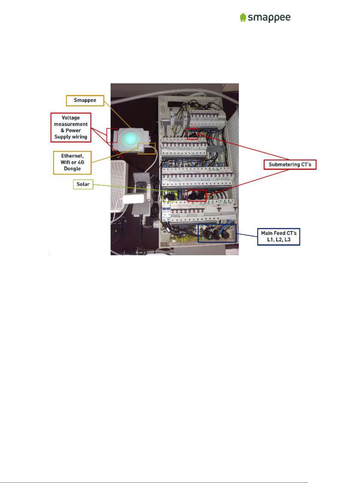
Example of a complete Smappee Pro Installation on 3-Phase 230V installation with a SinglePhase solar wiring harness used for voltage measurement and power supply. Ethernet used for
internet connection.
Page 10
Smappee Pro Installation and Product Manual Page 10 of 74
Version 2.0.0, 24-09-2018, rev 102
Smappee Pro components
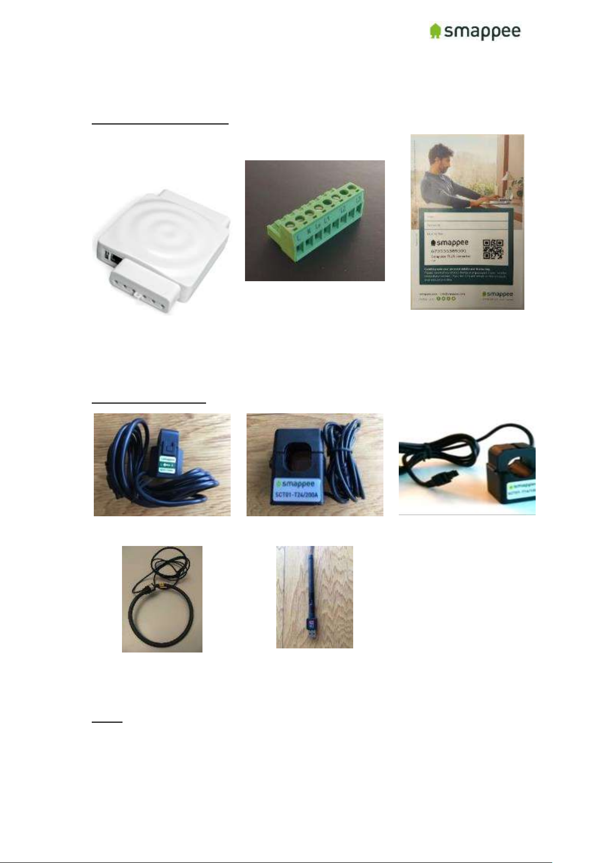
What comes in the box
Smappee Pro monitor
(The brain!)
Voltage Terminal
(power supply, measures
voltage of power phases)
Smappee License Key
(unique id for app)
Optional Hardware
Current Transformer 50A
Current transformer 100A
Current transformer 200A
Rogowski Coil 1000A
External Wi-Fi module
(connects Smappee to
internet and app)
Notes:
• 400A and 800A Current transformers also available (only for Smappee Pro)
• Different current transformer (standard and Rogowski) types can be mixed on a Smappee
Pro. There are exceptions depending on the setup.
See section "Special Cases - Rogowski Coils" for more details.
Page 11
Smappee Pro Installation and Product Manual Page 11 of 74
Version 2.0.0, 24-09-2018, rev 102
Planning and site preparations for Smappee
Pro installation
Prior to installing, complete the following items and gather the appropriate tools and supplies
necessary to complete the installation:
• Choose which loads to measure (Main Service, Solar, HVAC, Pool Pump, EV charger,
etc.) and determine where their circuit breakers are located (main service panel,
sub-panel).
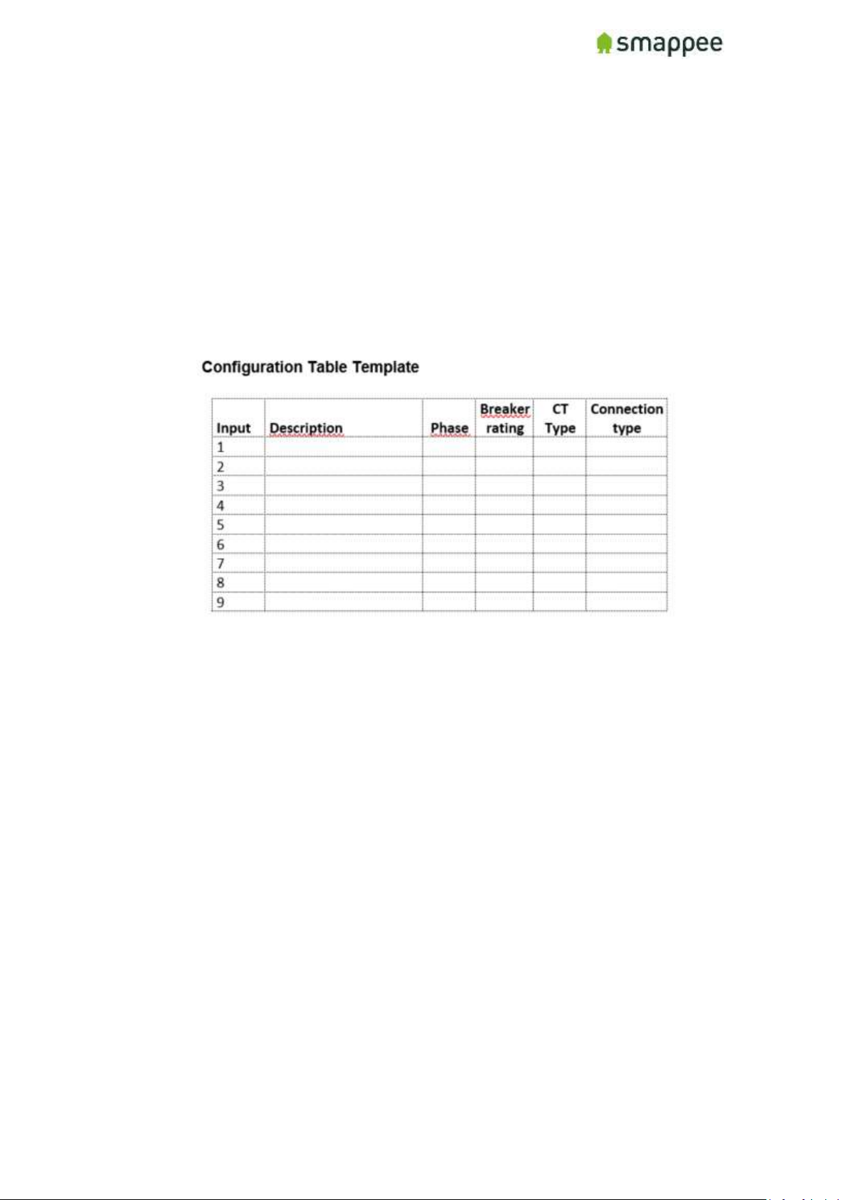
Fill in the Configuration template (see Appendix)
• Verify there is space to install CT’s on these circuits. (See Appendix for examples
and template)
• Verify the service voltage – Single-, 3-Phase (230-400V or 277-480V systems, delta
or star configuration)
• Complete the configuration table in the appendix section for each load to be
measured including description, phase, breaker rating and whether it is a 230V or
400V load.
Note: the power supply of the Smappee may only be 230V.
• Determine if there is adequate space to mount Smappee Pro adjacent to the panel.
• Assess existing breakers in the electric panel to determine if there is an available
differential switch to mount the main feeder CT’s.
• Select the best method of connecting to internet and verify signal (ethernet, Wi-
Fi…).
• Download the latest Smappee app on smartphone or tablet.
Tools: Multimeter, screwdrivers (mini flathead and phillips), wire strippers, flashlight, needle
nose pliers, sharpie and utility knife. (Optional: drill and drill bits, hammer).
Supplies (not included): Zip ties, (Optional: 2-pole 10A/15A breaker, wire nuts, junction box -
8” x 8” x 4” or larger, conduit, fittings). Labels to identify the CT’s.
Page 12

Smappee Pro Installation and Product Manual Page 12 of 74
Version 2.0.0, 24-09-2018, rev 102
Overview installation - Step-by-Step
1.
Turn off Power
2.
Remove panel cover
3.
Mount Smappee Pro monitor
4.
Connect the voltage measurement and power supply wiring
5.
Connect current transformers (CT’s)
6.
Plug in the internet connection
7.
Verify and replace covers
8.
Turn on Power
9.
Smappee account creation and activation
10.
Smappee channel input configuration
10.a
Configuration – Expert Portal (Recommended)
10.b
Configuration – Smappee app
11.
Final installation checkup
11.a
Final installation checkup – Expert Portal (Recommended)
11.b
Final installation checkup – Smappee app
12.
Share Smappee with other Smappee user
Page 13
Smappee Pro Installation and Product Manual Page 13 of 74
Version 2.0.0, 24-09-2018, rev 102
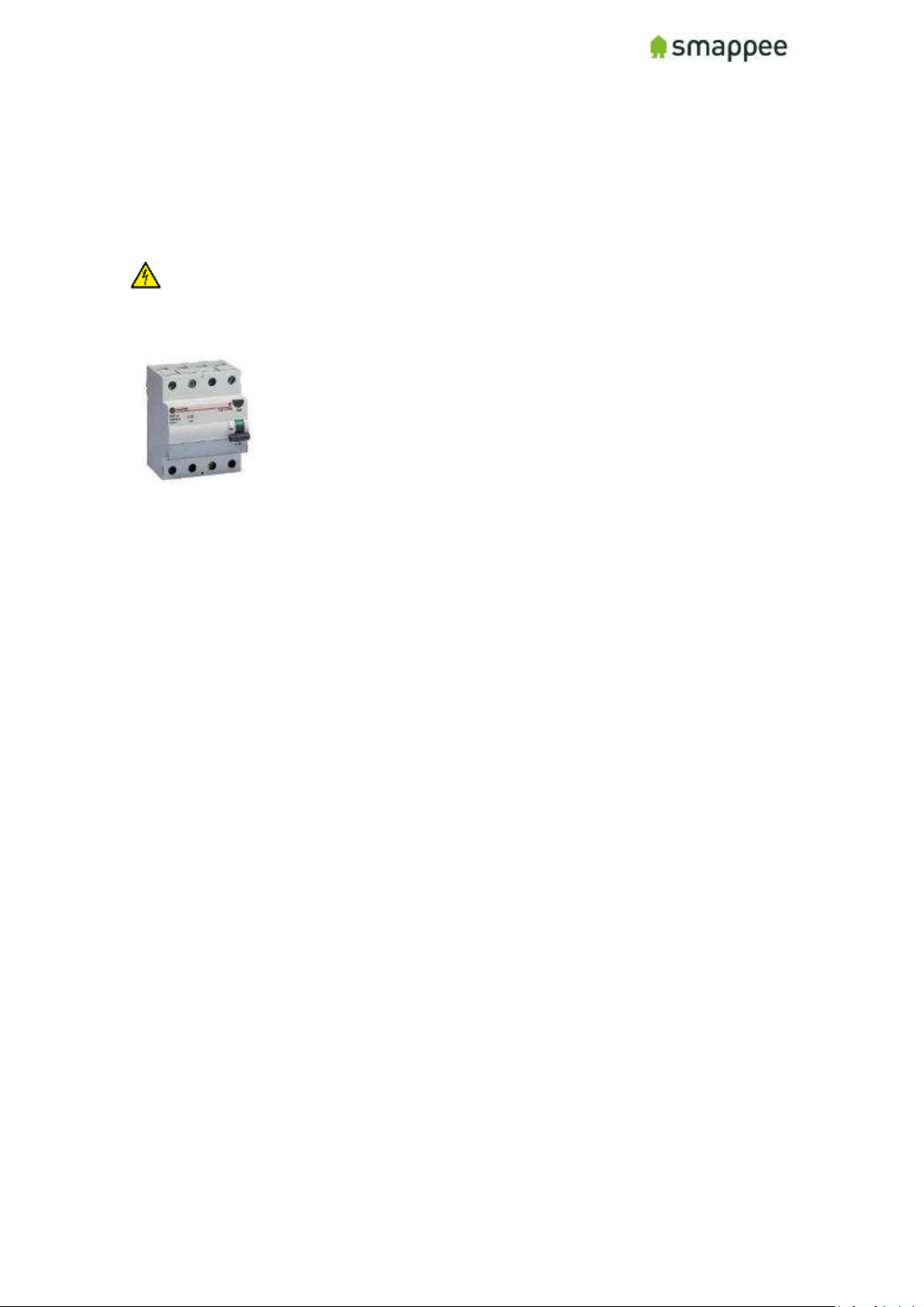
Step 1: Turn off Power
Open main electrical panel and shut off the main breaker. If you have a solar electric system,
shut off the inverter(s) and wait at least 5 minutes. Be sure to have a flashlight, PPE and all
tools and supplies readily accessible before starting.
WARNING: Use lock-out tag-out procedures to ensure power remains off until Smappee
installation is complete.
OFF position main breaker (differential switch)
Page 14
Smappee Pro Installation and Product Manual Page 14 of 74
Version 2.0.0, 24-09-2018, rev 102
Step 2: Remove panel and Smappee covers
Remove the screws that secure the panel cover to reveal the wires going to each breaker and
the main feeders from the utility going to the main breaker. If the loads to be measured are in
a sub-panel, open that panel instead.
WARNING: Wires and other parts inside the main panel may still be energized upstream
from the main breaker even after it is shut off so use caution.
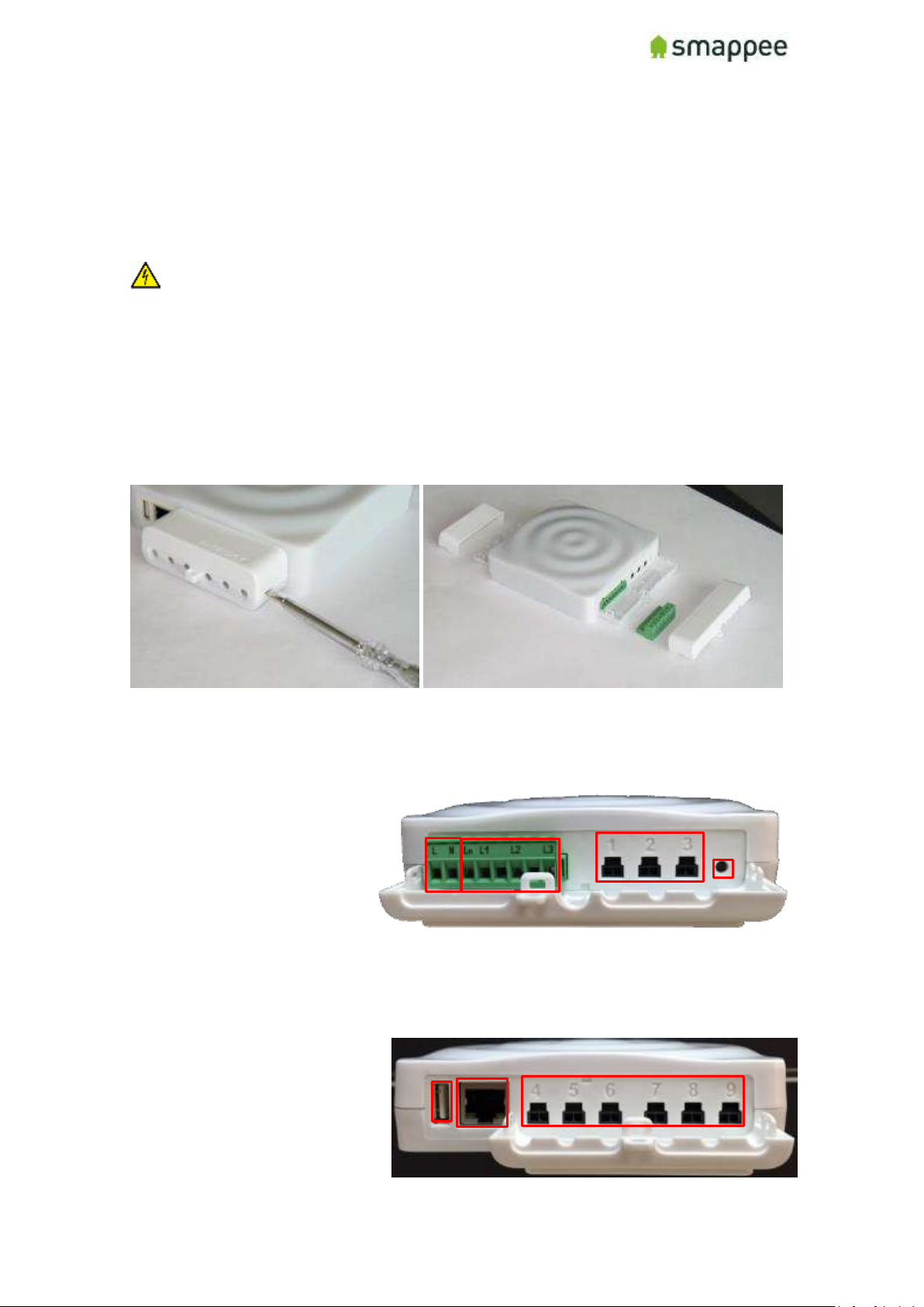
Accessing the Connectors
To get full access to all connectors of the Smappee monitor, you should remove the two
covers.
For removing the covers, insert a screwdriver at the sides of the covers and carefully
pull up the cover.
Connectors at the Front
The picture shows the connectors at the front.
• Power supply
• Voltage terminal
• CT connectors 1 to 3
• Reset button
Connectors at the Back
The picture shows the connectors at the back.
• USB port
• Ethernet port (LAN)
• CT connectors 4 to 9
Page 15

Smappee Pro Installation and Product Manual Page 15 of 74
Version 2.0.0, 24-09-2018, rev 102
Step 3: Mount Smappee Pro monitor
Find a suitable location just outside of the electrical panel and mount the Smappee Pro monitor
to the wall using screws. Note: The Smappee can only be mounted indoors.
Hint:
• If the Smappee is mounted inside a metal box, use only Ethernet Connection.
Wi-Fi or 4G can be disturbed.
• Take a photo of the serial number on the side of the monitor prior or write it
down to mounting for easy scanning later when configuring the system.
Monitor mounted on wall electric panel
Monitor positioned on top of electric panel
Page 16
Smappee Pro Installation and Product Manual Page 16 of 74
Version 2.0.0, 24-09-2018, rev 102
Step 4: Connect the voltage measurement and power
supply wiring
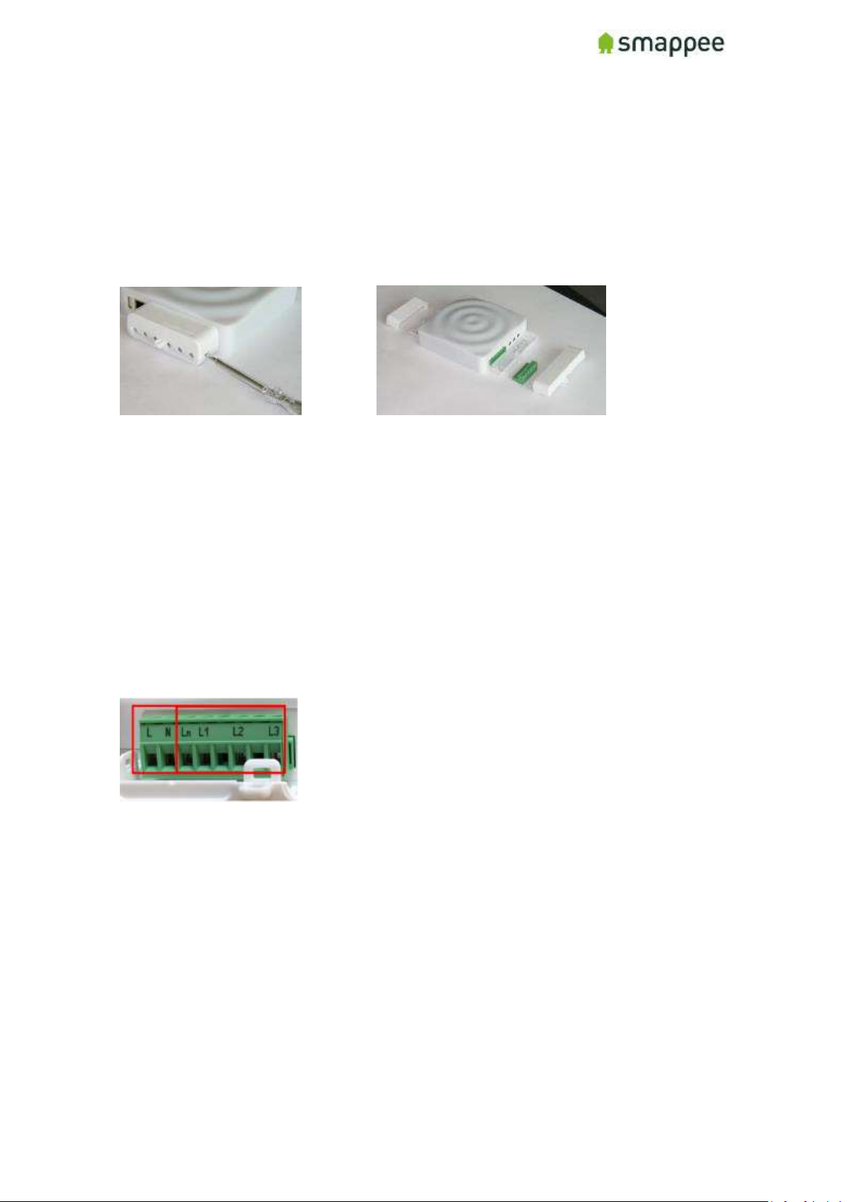
Remove the Smappee Pro monitor covers with a flathead screwdriver and locate the wiring
harness unit (green 8-pin connector block)
For 230-400V or 277-480V systems, single- or 3-Phase electric service, locate an appropriate
breaker to mount the voltage wiring. If possible, mount an additional breaker for the Smappee
Monitor.
All wires used should have a diameter between 0.75 and 2.5mm².
Smappee measures the various voltages and individual phases and the Neutral wire of the
electrical installation if present. These wires need to be connected to the inputs of the green 8pin connector block.
Input overview:
• L - N: Power supply (between 100 and 240V)
• L1 - L3: Measurement inputs for the voltage and phase of each phase wire.
• Ln: Measurement input for the Neutral reference.
Notes:
• To measure the Neutral reference correctly, always connect the Input Ln
explicitly to the Neutral wire. There is NO internal link with the Neutral line of
the main power supply.
• A circuit breaker should always be used for the power supply. The circuit
breaker should be located close to the monitor and be easily reachable.
Page 17
Smappee Pro Installation and Product Manual Page 17 of 74
Version 2.0.0, 24-09-2018, rev 102
• The circuit breaker should always be the disconnecting device for the Smappee
monitor.
• All wires used should have a diameter between 0.75 and 2.5mm².
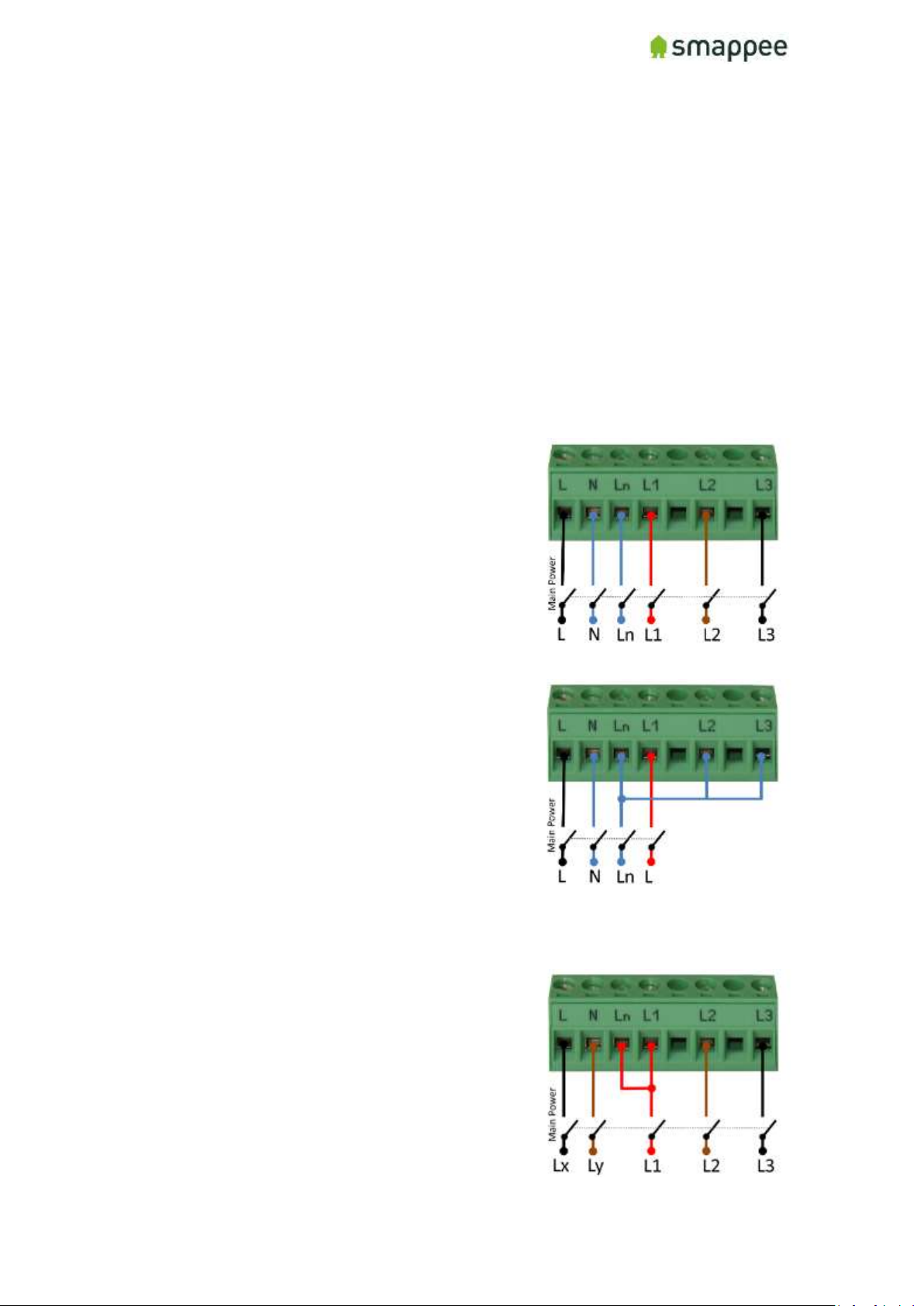
Installation Variants
There are three different Installation Variants (cfr. Europe):
• 3-Phase with Neutral ("Star")
• Single-Phase
• 3-phase without Neutral ("Delta")
Note: Split-Phase is also supported. For details contact Smappee.
3-Phase with Neutral ("Star")
1. Identify the three phase cables L1, L2 and
L3 as well as the Neutral cable.
2. Connect the Neutral to the Ln.
3. Connect the phase cables to the correct
input of the voltage measure terminal:
• Phase cable L1 to input L1
• Phase cable L2 to input L2
• Phase cable L3 to input L3
Single-Phase
1. Identify the phase cable L1 and the
Neutral cable.
2. Connect the Neutral cable to the Ln, L2
and L3 input.
Connect the phase cable L1 to the L1 input.
3-Phase Without Neutral ("Delta")
1. Identify the three phase cables L1, L2 and
L3.
2. Connect the first phase cable L1 to the
Neutral input Ln.
3. Then connect the phase cables to the
corresponding connectors of the voltage
measure terminal:
• Phase cable L1 to the input L1
• Phase cable L2 to the input L2
Page 18
Smappee Pro Installation and Product Manual Page 18 of 74
Version 2.0.0, 24-09-2018, rev 102
Phase cable L3 to the input L3
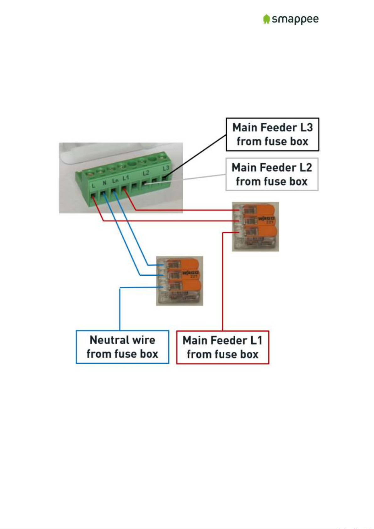
Hints: When no auxiliary power supply is used, you can create branches using wagos for voltage
wiring.
Page 19
Smappee Pro Installation and Product Manual Page 19 of 74
Version 2.0.0, 24-09-2018, rev 102
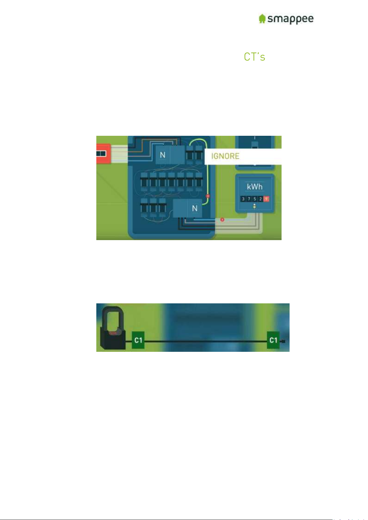
Step 5: Connect current transformers ( )
Attach the Smappee current transformers (CT’s) around the circuits that were selected to be
measured during the planning stage. Refer to the configuration table (appendix) that was
completed at the planning stage to ensure you are connecting the correct CT’s on the correct
phases.
1. Identify the phase wires
Hint: Label both ends of the CT’s with the included labels, so it is easy to
identify which load and phase they correspond to when plugging into the
Smappee Pro monitor and later when configuring on the Smappee app.
Page 20
Smappee Pro Installation and Product Manual Page 20 of 74
Version 2.0.0, 24-09-2018, rev 102
2. Respect the polarity of the clamp
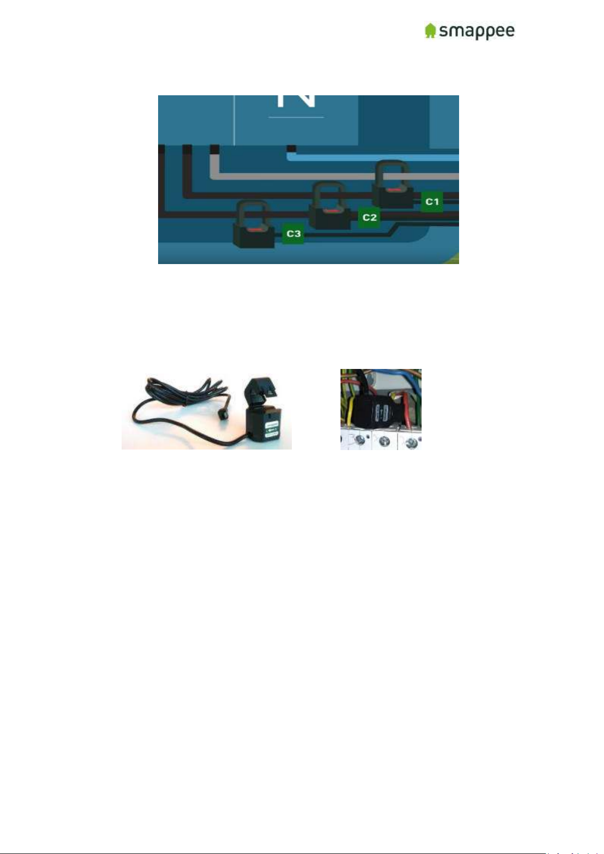
Open the CT, wrap it around the circuit and then close it tight.
Note: Pay close attention to the direction of the arrow on the CT. The arrow always
points towards the electrical load (i.e. in the direction of the energy flow).
Use one CT on each phase of the load and ensure it has a rating equal to or greater
than the breaker rating protecting the circuit (i.e. 200A CT for a main circuit with a
200A breaker rating). Then plug the other end of the CT into the corresponding inputs
(1-9) on the Smappee Pro monitor.
Page 21

Smappee Pro Installation and Product Manual Page 21 of 74
Version 2.0.0, 24-09-2018, rev 102
3. If Solar or Battery storage is present:
• Identify the phases of the Solar/Battery inverter: Phase one of the
Main Feeder needs to be corresponding with the phase one of the
solar inverter (Phase Mapping). Validate using a Multimeter:
• The CT has to follow the direction of current so:
i. Production of solar is a positive value
ii. Battery discharging is a positive value, charging is negative.
In most cases is the correct direction of the CT’s away from to inverter
and towards the consumers.
Hint: also Label the CT’s of the solar Inverter.
4. To apply Submetering, a CT needs to be mounted on the phase wire (one with Single-
Phase, 3 when measuring 3-Phase). The configuration of the CT as total load or as
submetering is done in the configuration (see later).
Hints:
• Label each CT with a name and the corresponding phase on which it is
measuring
• Number each Main Feed Phase on the differential switch with a label.
• To check on which phase number of the Submeter are in comparison with Main
Feeder, using the Multimeter to check (see Solar)
Page 22
Smappee Pro Installation and Product Manual Page 22 of 74
Version 2.0.0, 24-09-2018, rev 102
IMPORTANT
• When submetering in a 3-Phase delta configuration, always mount a CT around
each phase.
• Smappee only supports CT’s that are or can be supplied. No other CT’s should
be used.
• Different current transformer (standard and Rogowski) types can be mixed on
a Smappee Pro. There are exceptions depending on the setup.
See section "Special Cases - Rogowski Coils" for more details.
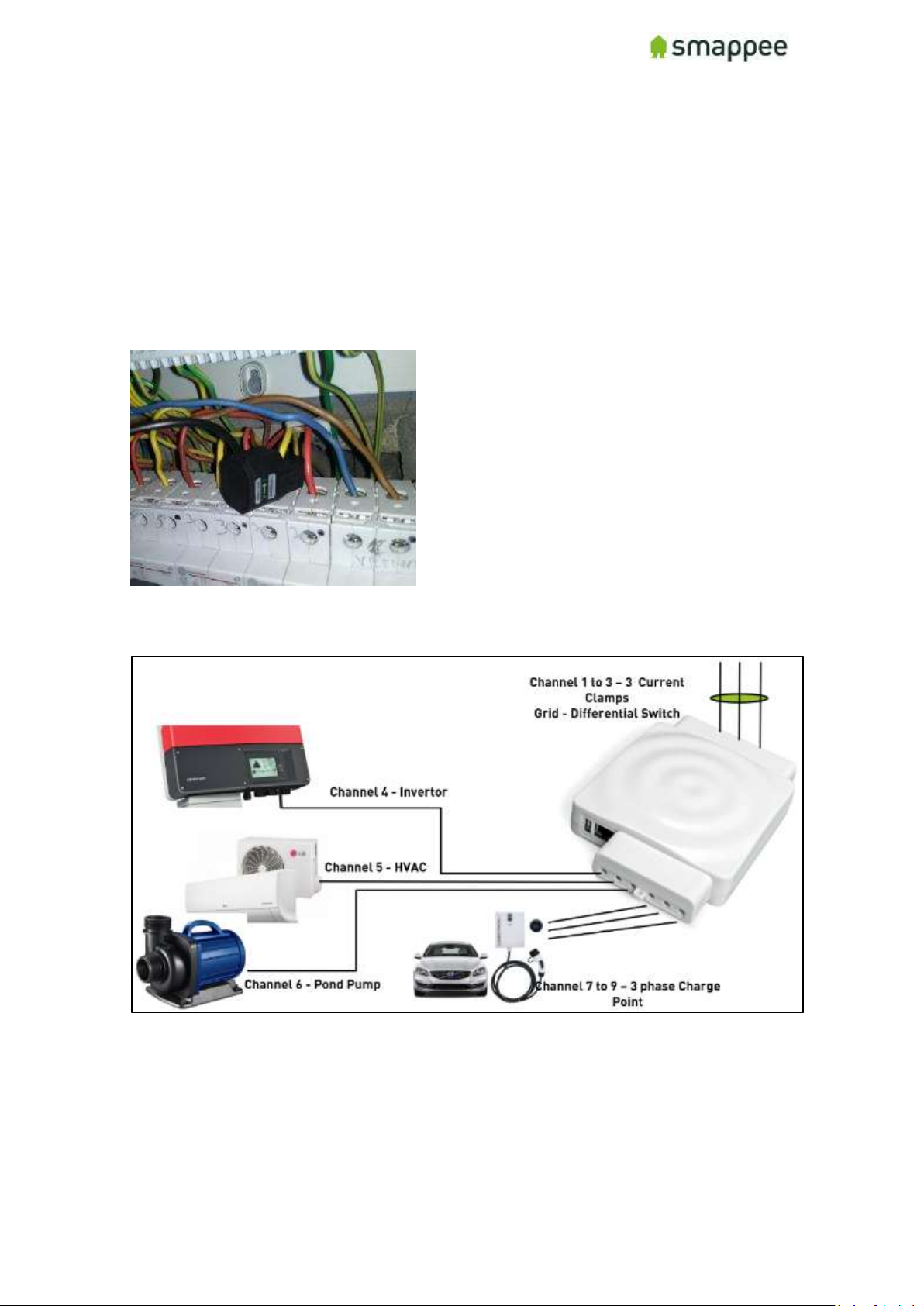
Example of submetering on a Single-Phase circuit in a 3-Phase Star configuration
Example of CT connection with a 3-Phase solar circuit and a 3-Phase main feed configuration.
Page 23
Smappee Pro Installation and Product Manual Page 23 of 74
Version 2.0.0, 24-09-2018, rev 102
Step 6: Plug in the internet connection
Choose the best method of connecting the Smappee Pro monitor to the internet from the
following options:
a) Ethernet cable
b) External Wi-Fi module (USB): This option requires a strong Wi-Fi signal from a
local network at the monitor. Plug the antenna into the USB port of the
monitor and follow the prompts on the Smappee app to establish connection.
c) 4G Dongle
Notes:
• The Wi-Fi dongle is only included with the Smappee Pro package, not with the
Smappee Pro (has to purchased separately)
• Ethernet is the preferred connection method, followed by Wi-Fi. 4G Dongle
only advised when no internet connection is available on the location.
• All network cables and USB devices must be inserted or removed while power
is OFF.
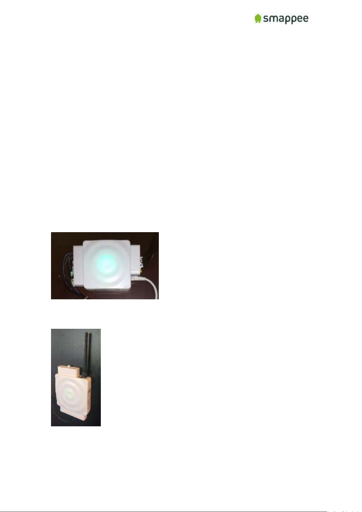
Smappee using Ethernet Connection
Smappee using Wi-Fi Connection
Page 24
Smappee Pro Installation and Product Manual Page 24 of 74
Version 2.0.0, 24-09-2018, rev 102
Step 7: Verify and replace covers
Verify all connections are properly made and are secure
• Electrical connections must be properly tightened and secured at the breakers,
8-pin connector block and at the Smappee Pro monitor CT inputs
• CT’s must be fully closed around circuits and snapped tight
• Wi-Fi antenna USB or ethernet cable must be plugged into the monitor (before
power ON)
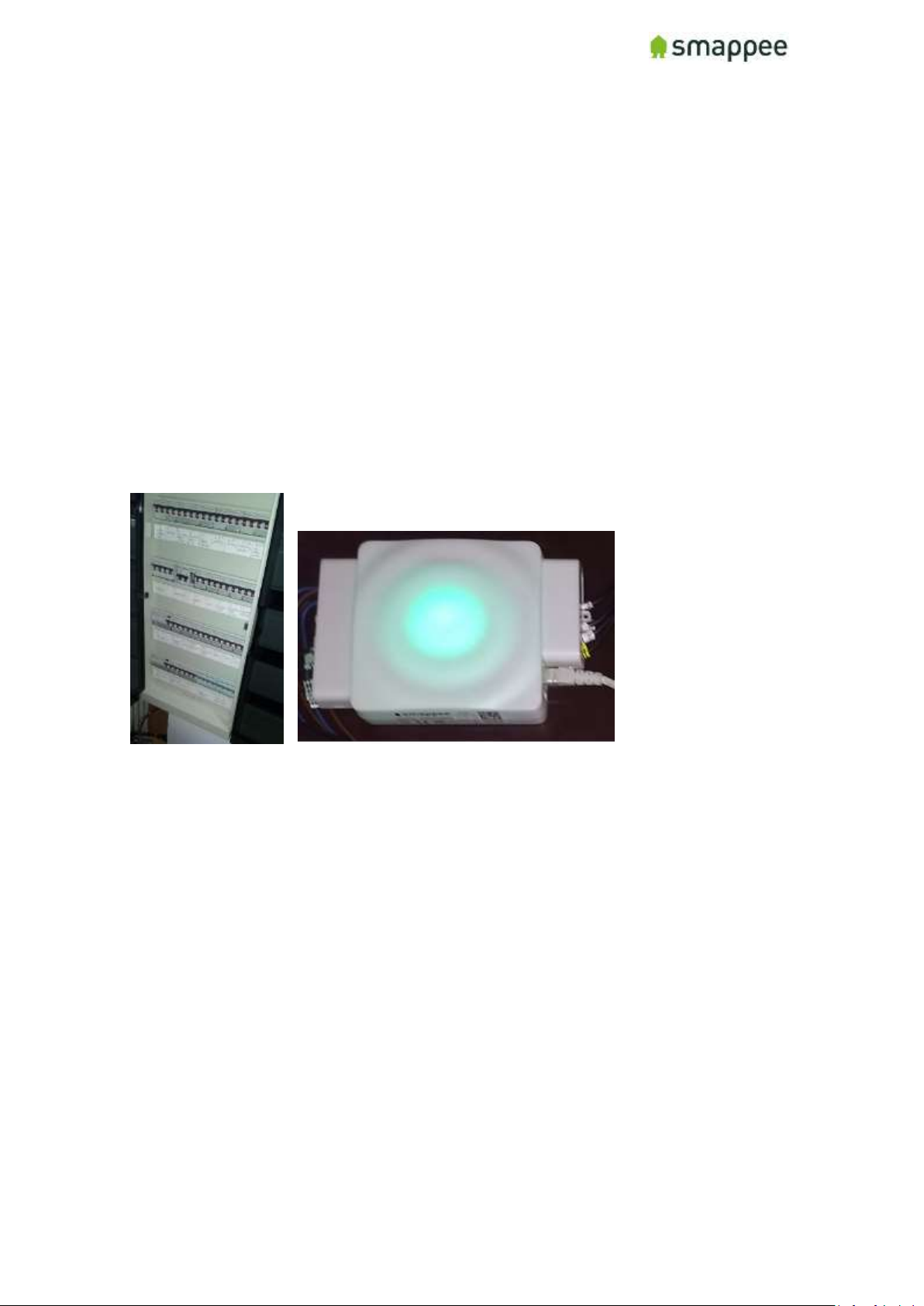
Replace the cover on the electrical panel and label the Smappee breaker(s). Then mount the
cover caps on the monitor to cover all electrical connections and use zip ties to secure
conductors together. If the monitor was installed inside a fuse box, keep the cover open during
the next two steps to observe the status lights.
Page 25
Smappee Pro Installation and Product Manual Page 25 of 74
Version 2.0.0, 24-09-2018, rev 102
Step 8: Turn on Power
Switch on the main breaker. Then switch on the power to the Smappee Pro monitor at the
breaker.
Smappee Pro will take at least 3 minutes to fully initiate once powered on for the first time. It is
advised to wait 5 minutes to review.
After this initiation, you should see either:
• Ethernet: Green steady light
• Wifi: Blue flashing light
• 4G dongle: Steady (Blue, Green, Cyan): Successfully connected. The dongle is
successfully connected to the cellular network.
If you see one of these colors, proceed to the next page of this manual.
If, however, Smappee shows a different color, please refer to section "Troubleshooting Internet
and Cloud Access"
Either of these light patterns indicate that Smappee is ready to be installed by the Smappee
app. If you don’t see either of these light patterns, visit
https://www.smappee.com/be_en/support/ to troubleshoot.
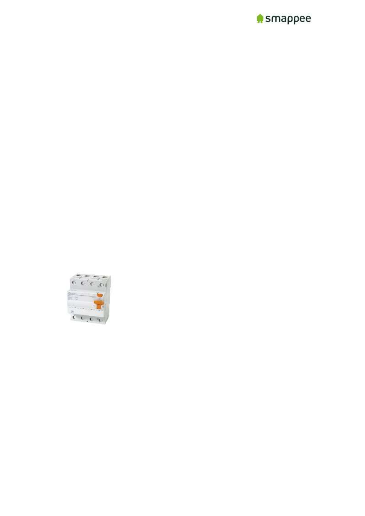
ON position main breaker (differential switch)
Page 26
Smappee Pro Installation and Product Manual Page 26 of 74
Version 2.0.0, 24-09-2018, rev 102
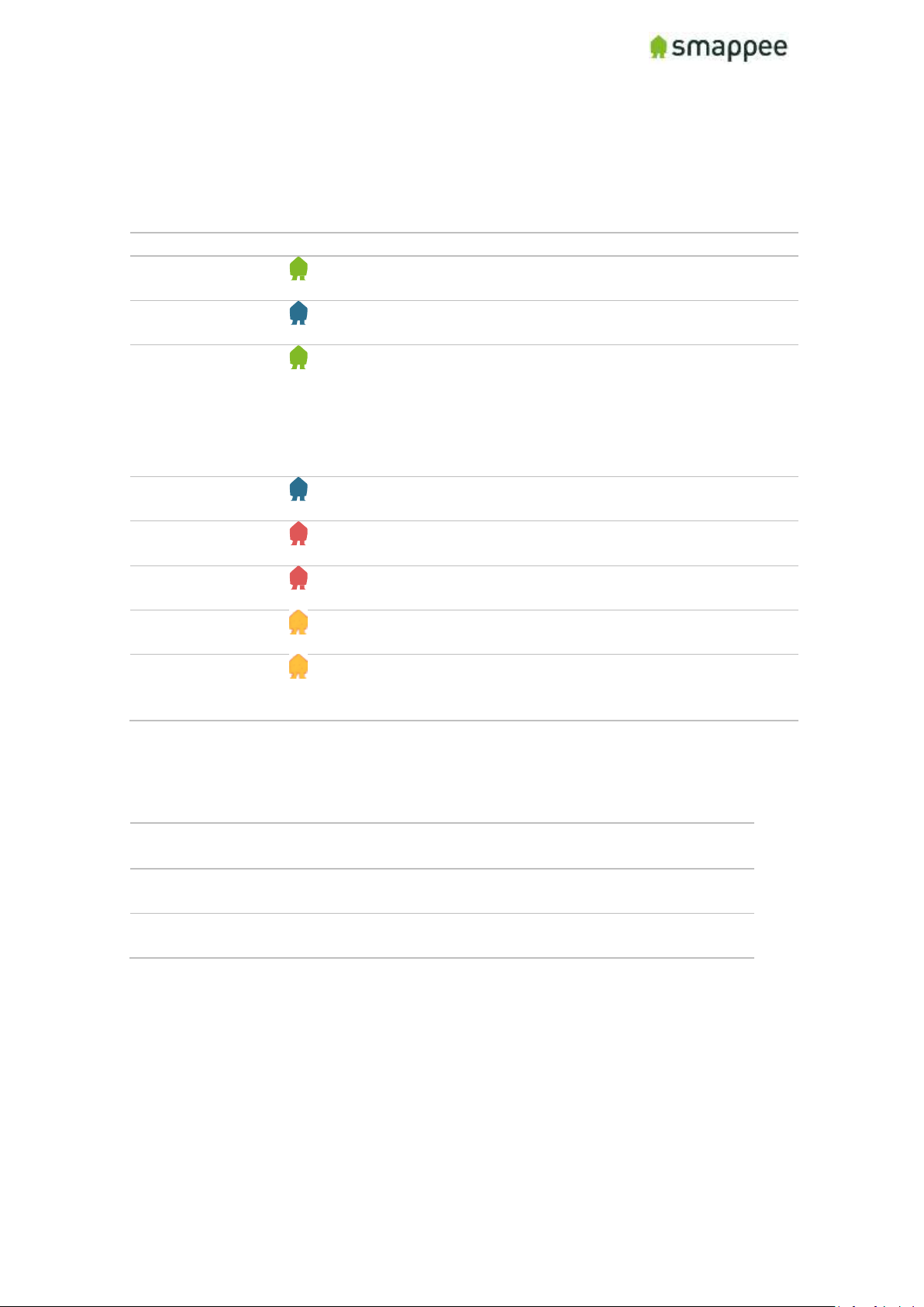
Colors of the Smappee Light
The table below provides an overview over all colors that may be shown during the
installation.
Color
Description
Green Breathing
All good. The monitor is working correctly. You can continue
the next steps for installation and configuration.
Blue Steady
The monitor is starting up. This may take up to 3 minutes.
The light may briefly go dark during that time.
Green Steady
Network connectivity successful, but Smappee not yet
connected to a user account.
• Ethernet: Connected to the local network.
• Wi-Fi: Connected to the Wi-Fi and the local network
(i.e. the Wi-Fi password is correct)
• 4G dongle: Connected to the 4G network.
Blue Flashing
The monitor is ready to be connected to the local Wi-Fi
network and to be installed on the App.
Red Steady
The monitor is missing connectivity with internet during
startup. Connection issue.
Red Flashing
The monitor had a previous working internet connection but
has now lost connectivity to the internet.
Orange Steady
The Wi-Fi hotspot access point has been activated, in order
to allow the Smappee to receive a new Wi-Fi password.
Orange Flashing
Smappee is trying to open an Wi-Fi hotspot access point.
Please wait a few seconds. The light will turn Orange Steady
in a few moments.
Colors of 4G dongle
Any steady
(Blue, Green, Cyan)
Successfully connected. The dongle is
successfully connected to the cellular network.
Any slow blinking
(Blue, Green, Cyan)
The dongle is registering with a cellular network.
Green fast blinking
(1 per second)
Stick is powered on. No connection.
Page 27

Smappee Pro Installation and Product Manual Page 27 of 74
Version 2.0.0, 24-09-2018, rev 102
Wi-Fi connection details
In case of Wi-Fi connection problems, check the following points:
a. 2.4 GHz Wi-Fi required, preferably with automatic channel selection
b. WPA or WPA2 encryption mandatory
c. Networks without security are not supported
d. SSID needs to be visible and may not be hidden during install
e. Make sure that your SSID does NOT contain one of the following characters:
é,ç,è,ä,/\, ", à î ô ï
f. Allow special characters for the Wi-Fi password: #$%@?/ \
g. Double-check your password
h. Double-check that your smart phone is connected to the correct Wi-Fi network, not
to a hotspot or other networks where you have your password configured
i. If you use WPS, check that it is active on the router
j. Make sure that MAC filtering is not active
k. Your firewall should allow Smappee to create https outbound connections (port
443)
l. Parental control also might prevent internet access based on time of day
m. The maximum number of characters for the WPA2/PSK when using an iOS device
during installation is 20.
Note: The IP address of Smappee is assigned by the DHCP of your router.
Page 28
Smappee Pro Installation and Product Manual Page 28 of 74
Version 2.0.0, 24-09-2018, rev 102
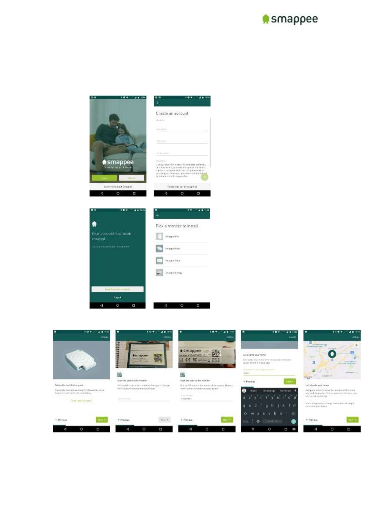
Step 9: Smappee account creation and activation
The Smappee account creation and activation is done in the Smappee app.
1. Create an account.
2. Select “Install a new Smappee monitor” then select “Smappee Pro”.
3. Start the installation and follow the instructions in the app for activation of your
Smappee.
Page 29
Smappee Pro Installation and Product Manual Page 29 of 74
Version 2.0.0, 24-09-2018, rev 102
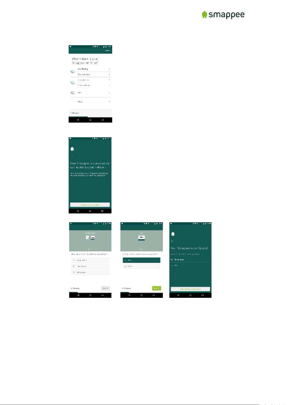
4. Select which color the Smappee is showing and follow the instructions in the app.
5. Proceed to “Configuration” once the Smappee Pro monitor has successfully
connected to the network.
6. Select home electrical configuration: Single- or 3-Phase (Star or Delta)
Page 30
Smappee Pro Installation and Product Manual Page 30 of 74
Version 2.0.0, 24-09-2018, rev 102
Step 10: Smappee channel input configuration
For the channel input configuration, 2 methods can be used:
• Expert Portal (10.a)
• Smappee mobile app (10.b)
Using the Expert Portal is recommended as it displays more values in real-time which enables
better and faster validation of the installation and configuration. The usage of the expert portal
is not suited for small mobile devices. Best option is a tablet or using a laptop.
The following parameters can be configured for each input are equal for both Expert Portal or
Smappee app. This is a critical step and you should refer to the configuration table created
during the planning stage (see Appendix):
This table shows the settings for the configuration of each CT.
Setting
Description
Input
Number of the Input connector on the Smappee.
Name
Provide a name for this specific input.
Note: You should carefully select an unmistakable name, since it is used in
many user-facing locations on the websites and the App.
Phase
Configure the phase that the CT of this specific input is measuring.
Type
In the type menu, you can choose between 3 options:
• Consumption (load)
• Production (solar, wind,…)
• Storage (Batteries,…)
• Unused
Connection
Here you can choose what connection type the CT is:
• Grid - CT measures the total consumption of the installation
• Off-Grid - CT measurements are added on top of the total
• Submeter - CT measurements are sub-sets within the total
Reversed
Select this checkbox to invert the 'direction' of the current transformer. This
option is equivalent to physically re-install the CT with the arrow pointing in
the other direction.
Note: This option should only be used if it is physically impossible to install
the CT correctly.
NILM (Appliance
Detection)
Select this checkbox to activate the automatic appliance detection on that
particular input.
Balanced 3x
When selected, the CT measures (only) one phase of a three-phase line, and
extrapolates the total power over the three phases.
This setting is useful for submetering of three-phase load with a single
Current Transformer. It yields good results as long as the load over the
three phases is "balanced".
CT Type
Here you can configure the Current Rating of the current transformer that is
connected in that input. (50A-100A-200A-400A-800A).
Please refer to section "Configuration Settings for CT’s” for more details & for the use of
Rogowski Coils, see section "Special Cases - Rogowski Coils".
Page 31
Smappee Pro Installation and Product Manual Page 31 of 74
Version 2.0.0, 24-09-2018, rev 102
Step 10.a: Configuration Expert Portal
(Recommended)
Using the Expert Portal is recommended as it displays more values in real time which enables
better and faster validation of the installation and configuration. The usage of the expert portal
is not suited for small mobile devices. Best option is a tablet or using a laptop.
Note: The tablet or laptop needs to be connected to the same network as the Smappee
monitor to be able to use the Expert Portal.
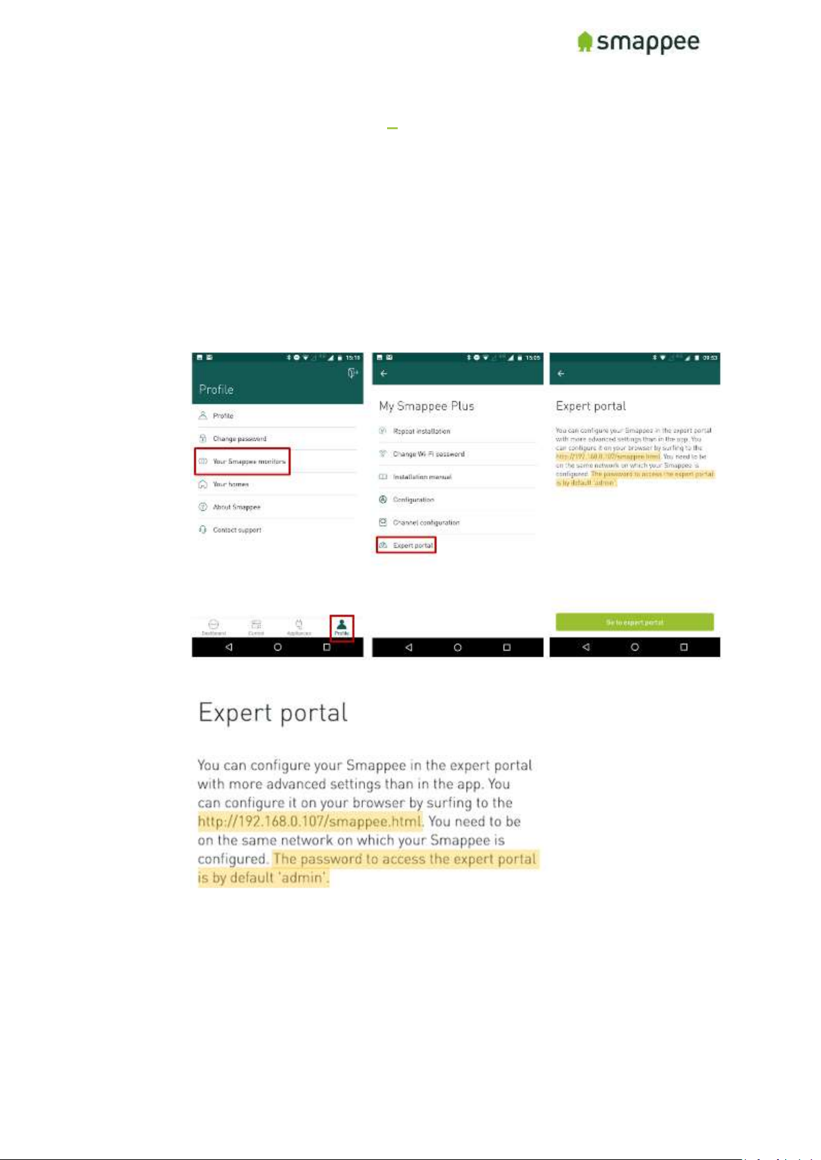
1. Go to the Smappee Pro using ‘Settings’ – select Smappee Pro
2. Fill in the URL mentioned in Smappee Expert Mode:
Page 32
Smappee Pro Installation and Product Manual Page 32 of 74
Version 2.0.0, 24-09-2018, rev 102
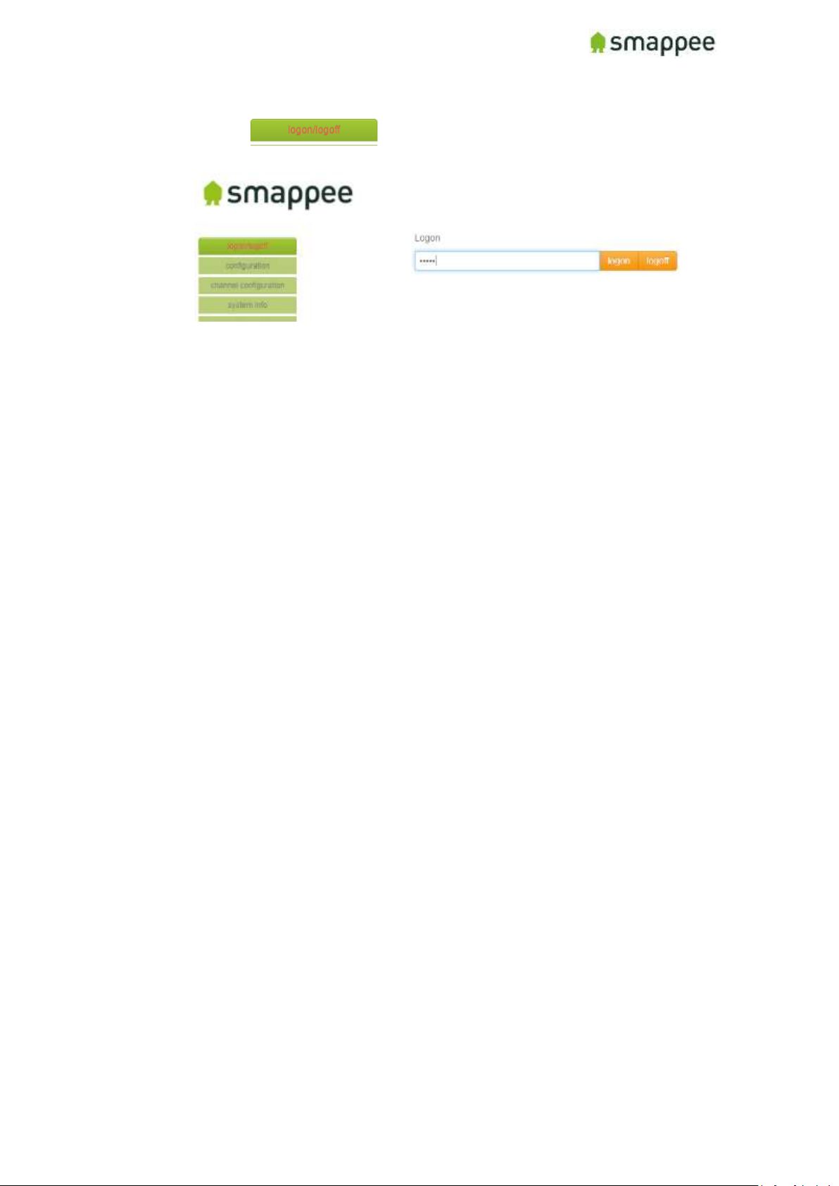
3. Click on and fill in password (see password in previous
screenshot)
Page 33
Smappee Pro Installation and Product Manual Page 33 of 74
Version 2.0.0, 24-09-2018, rev 102
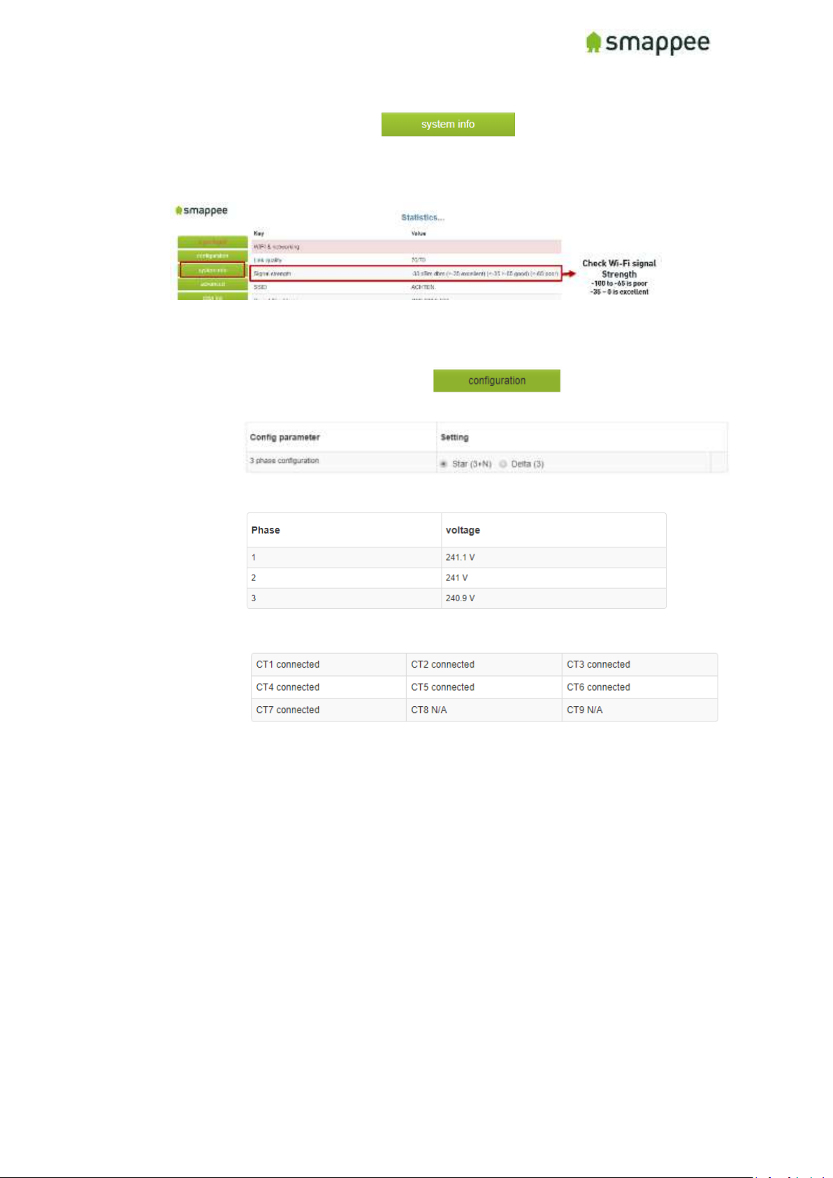
4. Wifi-connection only: click on and review the Signal strength:
• -100 to -65 is poor
• -65 to -35 is good (normal)
• -35 to 0 is excellent
If the signal strength is poor, please take action in order to increase the Wi-Fi signal
quality. The value updates in real time.
5. Actual installation validation: click on
• Review the Config Parameter (Star or Delta)
• Review if voltages are displayed and correct (displayed in real-time)
• Review if all channels to that are used are displayed as ‘connected’
Page 34
Smappee Pro Installation and Product Manual Page 34 of 74
Version 2.0.0, 24-09-2018, rev 102
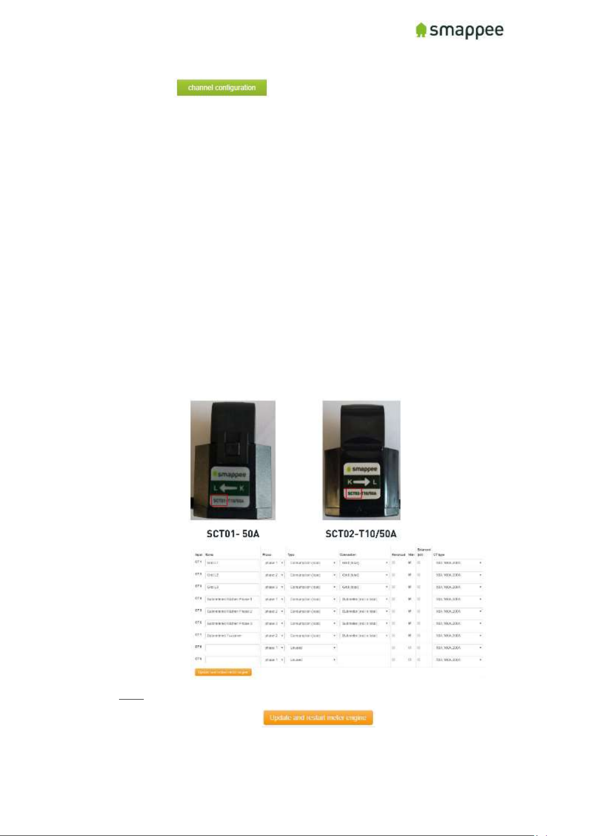
6. Click on and setup each channel (1-9):
• Enter the Name from the configuration table (i.e. Main Feed, Solar, EV,
Submeter).
• Select the phase of the channel (load) (i.e. 1, 2, 3) => Later on, the phase-
mapping will be validated using the process description later on.
• Choose Consumption type, whether it is a Consumption load, Production,
(solar/wind), Storage (battery) or Unused load.
• Select the Connection load type:
i. Grid - CT measures the total consumption of the installation
ii. Off-Grid - CT measurements are added on top of the total
iii. Submeter - CT measurements are sub-sets within the total
• Select Reversed if the direction of the CT (channel) is inverted and you are
unable to install the CT correctly.
• Select NILM to activate automatic appliance detection on an aggregated
load (i.e. Main Service).
• Select Balanced if the CT measures only one phase of a 3-Phase line
(Software will multiply the measurement by 3).
• Select CT type to indicate current rating of the CT used. Review the
transformer type and sizing. Pay close attention to the type indication
“SCT01, SCT02 or SCT03” and amp size (e.g. 50A).
Note:
• After each change, click to store and activate
changes
Page 35
Smappee Pro Installation and Product Manual Page 35 of 74
Version 2.0.0, 24-09-2018, rev 102
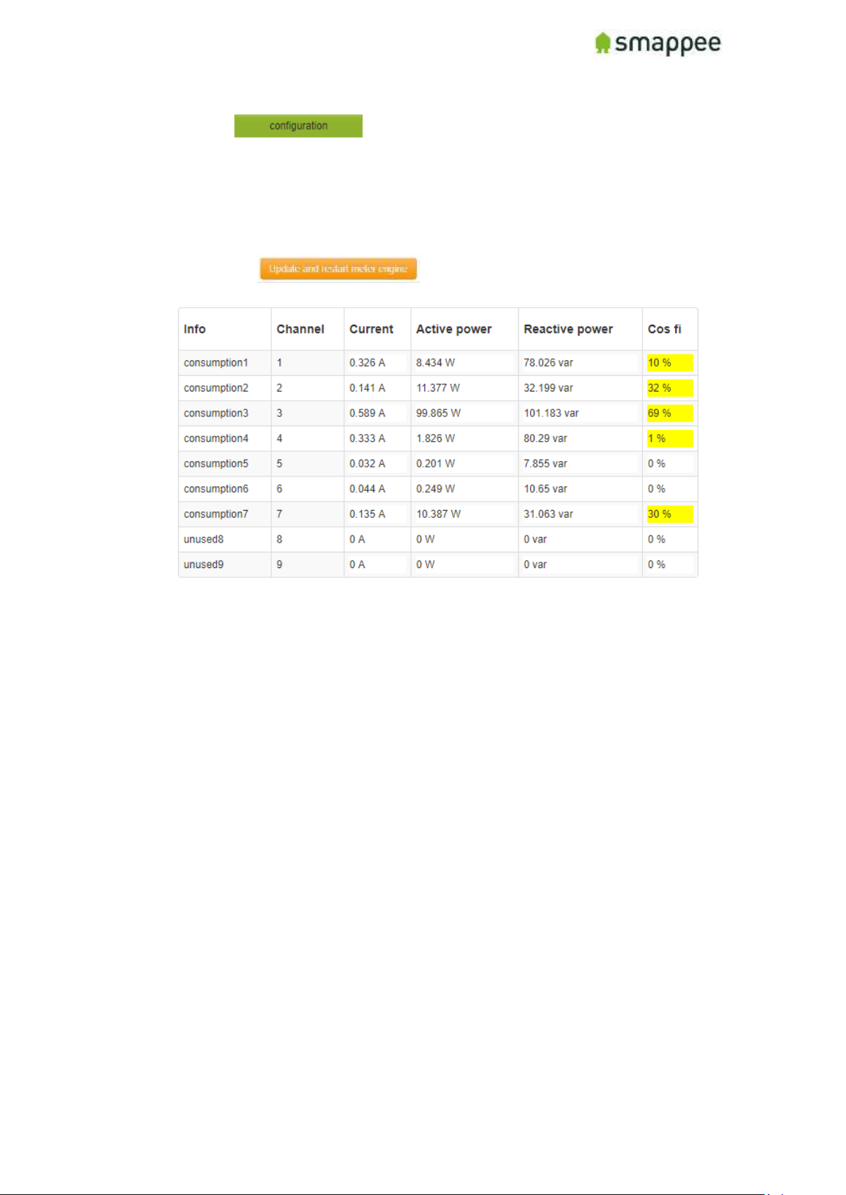
7. Click to review the channel inputs and validate that the
measurements are visible and updated in real time.
• For single-phase installations where you are sure that the location and
direction of the current clamps is correct, all values should be correct.
• For three-phase installations, the values could be incorrect. Please see the next
point (8).
Note: Repeat after each change.
Page 36
Smappee Pro Installation and Product Manual Page 36 of 74
Version 2.0.0, 24-09-2018, rev 102
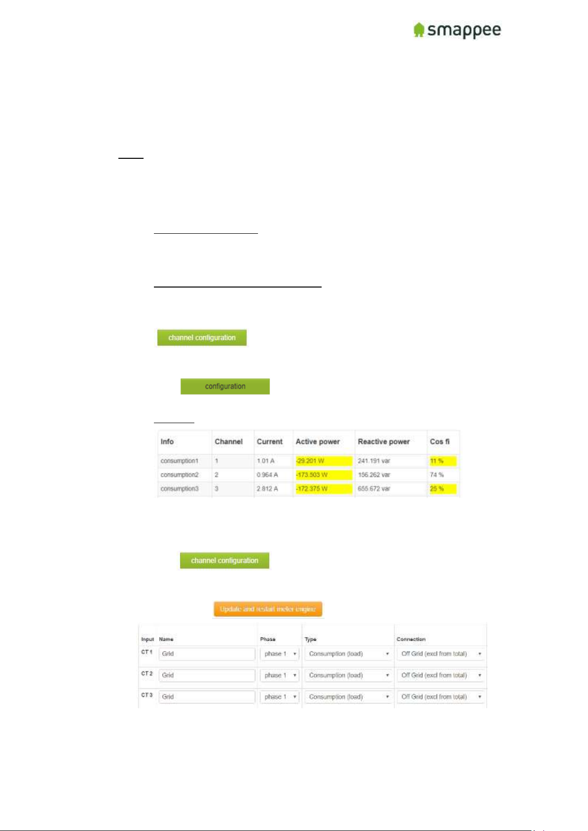
7. IMPORTANT: Phase-mapping setup – applicable 3 phase configuration only:
The phase-mapping needs to be correct to have accurate measurements. The phasemapping as setup in Smappee needs to correspond with real phase mapping from the
grid. This procedure explains how to validate and correct the phase-mapping.
Note: The screenshots below show the Active Power and Cos Fi are from an actual
residential environment. Other installation could and will in most cases show other
results.
PROCESS
1. Engage active power loads in the installation:
• Residential installations: Engage multiple appliances in the house have a power
consumption greater than 200W on each of the phases. This is done by
illuminating multiple lights, activate electric heater, electric oven, coffee
maker, hair dryer (resistive loads).
• Commercial & Industrial installations: if possible to engage loads which have
large active power consumption (and low reactive power).
2. If you were not able to mount the CT in the correction direction, Click
and reverse the appropriate channel(s).
See Point 6 above – Channel Configuration Overview.
3. Click and review the real time Active Power values and
Cos Fi
Example:
In this case, although the CT direction are correct, the absolute values for active
power are incorrect (too low) comparing to the actual power consumption in the
house. Also the Cos Fi is too low.
4. Click :
o Setup all 3 grid channels to phase 1
o Set Connection temporarily to “Off Grid (excl from total)”
o Click
Page 37
Smappee Pro Installation and Product Manual Page 37 of 74
Version 2.0.0, 24-09-2018, rev 102
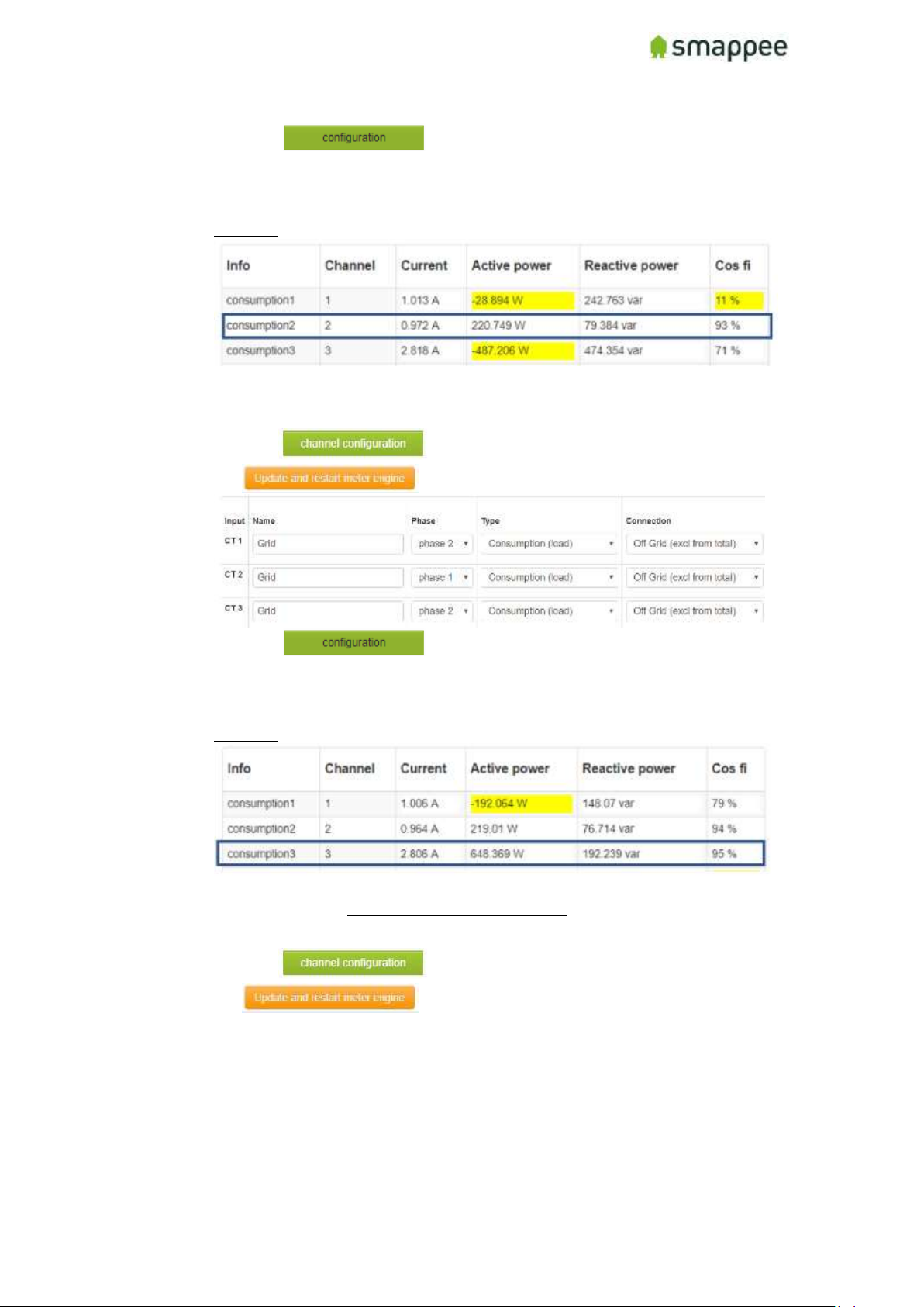
5. Click :
o Review which channel has the correct active power value with cos fi >
80%
o Remember channel number which is correct.
Example:
Channel 2 shows the correct Active Power value (positive and absolute) and Cos Fi
is > 80% => Remember Channel 2 = phase 1
6. Click - change the incorrect channels to phase 2 - click
7. Click :
o Review which channel has the correct active power value with cos fi >
80%.
o Remember channel number which is correct.
Example:
Now Channel 3 shows the correct Active Power value (positive and absolute) and
Cos Fi is > 80%. => Remember Channel 3 = phase 2
8. Click - change the incorrect channel to phase 3 - click
Page 38
Smappee Pro Installation and Product Manual Page 38 of 74
Version 2.0.0, 24-09-2018, rev 102
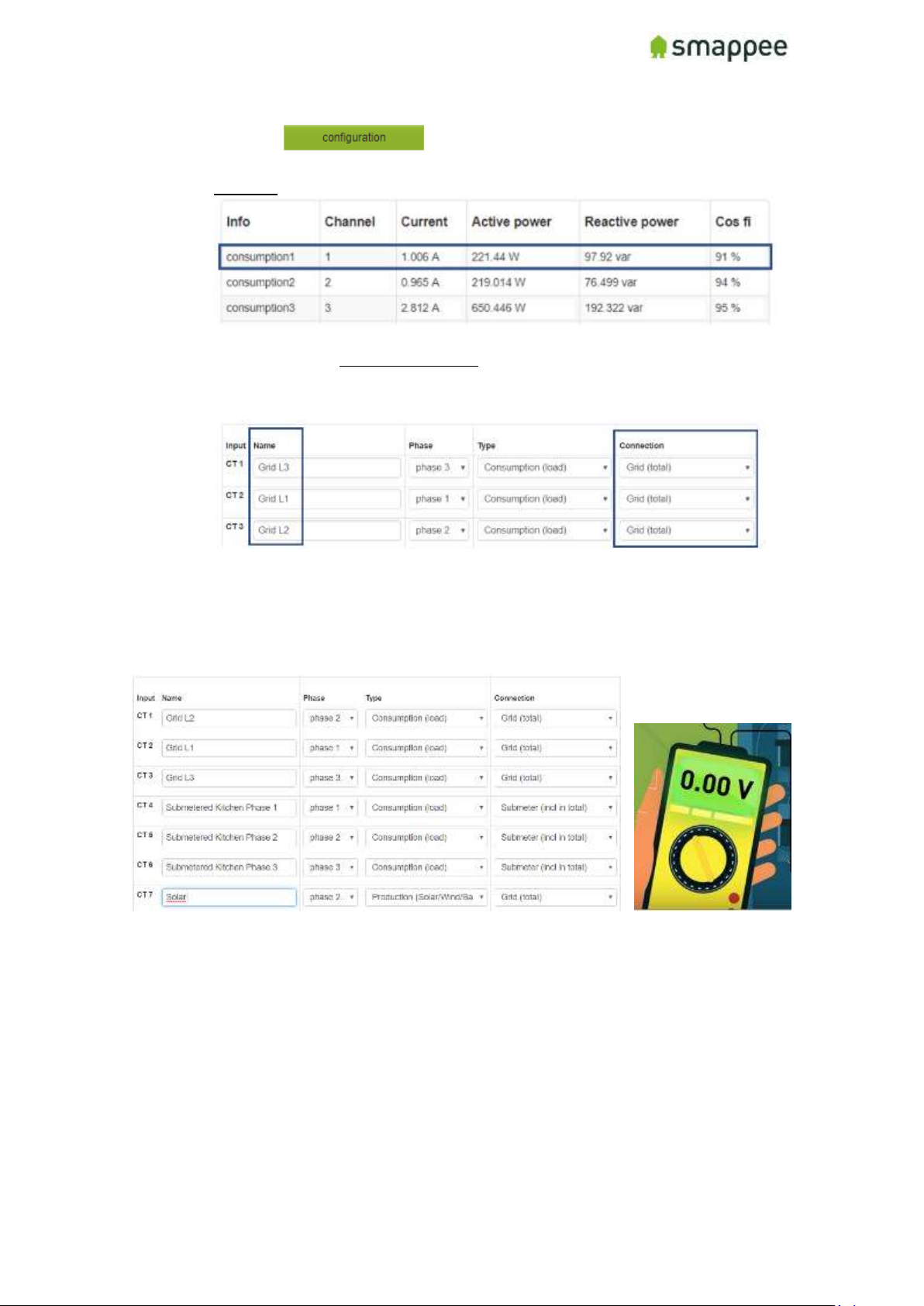
9. Click : review if all grid channels have correct (absolute
and positive values) with Cos Fi > 80%.
Example:
Now Channel 1 shows the correct Active Power value (positive and absolute) and
Cos Fi is > 80% => Channel 1 = phase 3
10. Set Grid channel back to “Grid (total)” and rename the channel accordingly.
8. If Submetering or solar is applicable, make sure that the phase-mapping
Submeter/solar – Grid connection corresponds with each other. Utilize a multimeter to
do so.
Page 39
Smappee Pro Installation and Product Manual Page 39 of 74
Version 2.0.0, 24-09-2018, rev 102
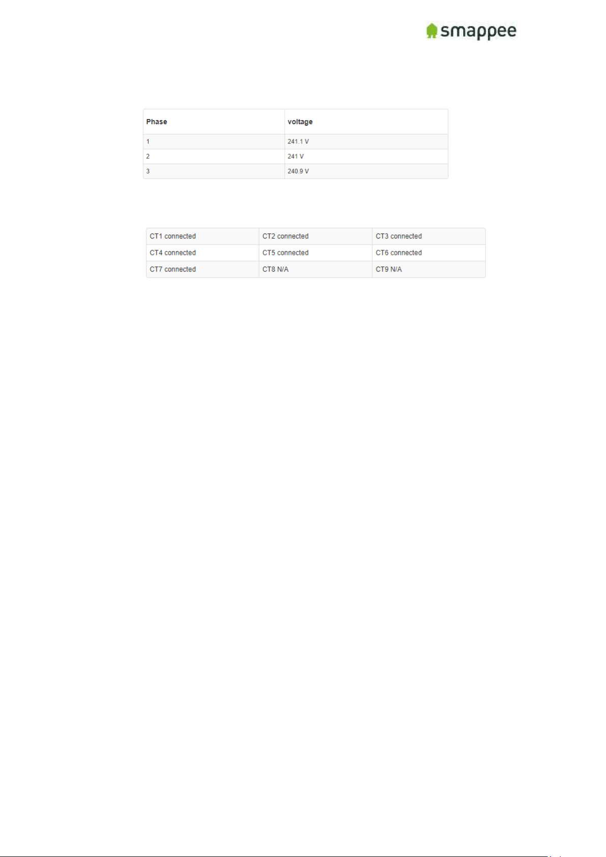
9. Before leaving the premises, make sure the voltage measurements are accurate and
all channel inputs that have a CT connected to display ‘Connected’ state:
measured between phase and neutral – Star & Delta = 230Volts
Page 40
Smappee Pro Installation and Product Manual Page 40 of 74
Version 2.0.0, 24-09-2018, rev 102
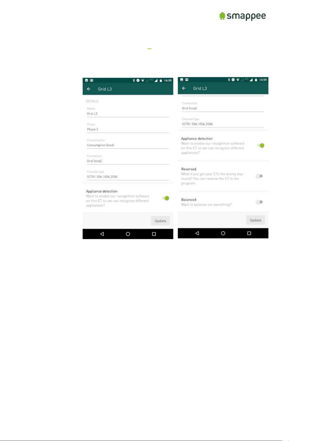
Step 10.b: Configuration Smappee app
a) Configure the CT channels and then save. This is a critical step and you should refer to
the configuration table created during the planning stage:
• For each input channel being used (1-9), enter the Name from the
configuration table (i.e. Main Feed, Solar, EV, Submeter).
• Select the phase of the channel (load) (i.e. 1, 2, 3). The phase-mapping needs
to be correct to have accurate measurements. The phase-mapping as setup in
Smappee needs to correspond with real phase mapping from the grid.
• Choose Consumption type, whether it is a Consumption load, Production,
(solar/wind), Storage (battery) or Unused load.
• Select the Connection load type: Grid (total), Off grid (excl. from total),
Submeter (incl. in total).
Select Reversed if the direction of the CT is inverted (if Active Power is
negative) and you are physically unable to install the CT correctly.
• Select NILM to activate automatic appliance detection on an aggregated load
(i.e. Main Service).
• Select Balanced if the CT measures only one phase of a 3-Phase line (Software
will multiply the measurement by 3).
• Select Channel type to indicate current rating of the CT used (50A, 100A, 200A
or others (Smappee Pro only).
Page 41
Smappee Pro Installation and Product Manual Page 41 of 74
Version 2.0.0, 24-09-2018, rev 102
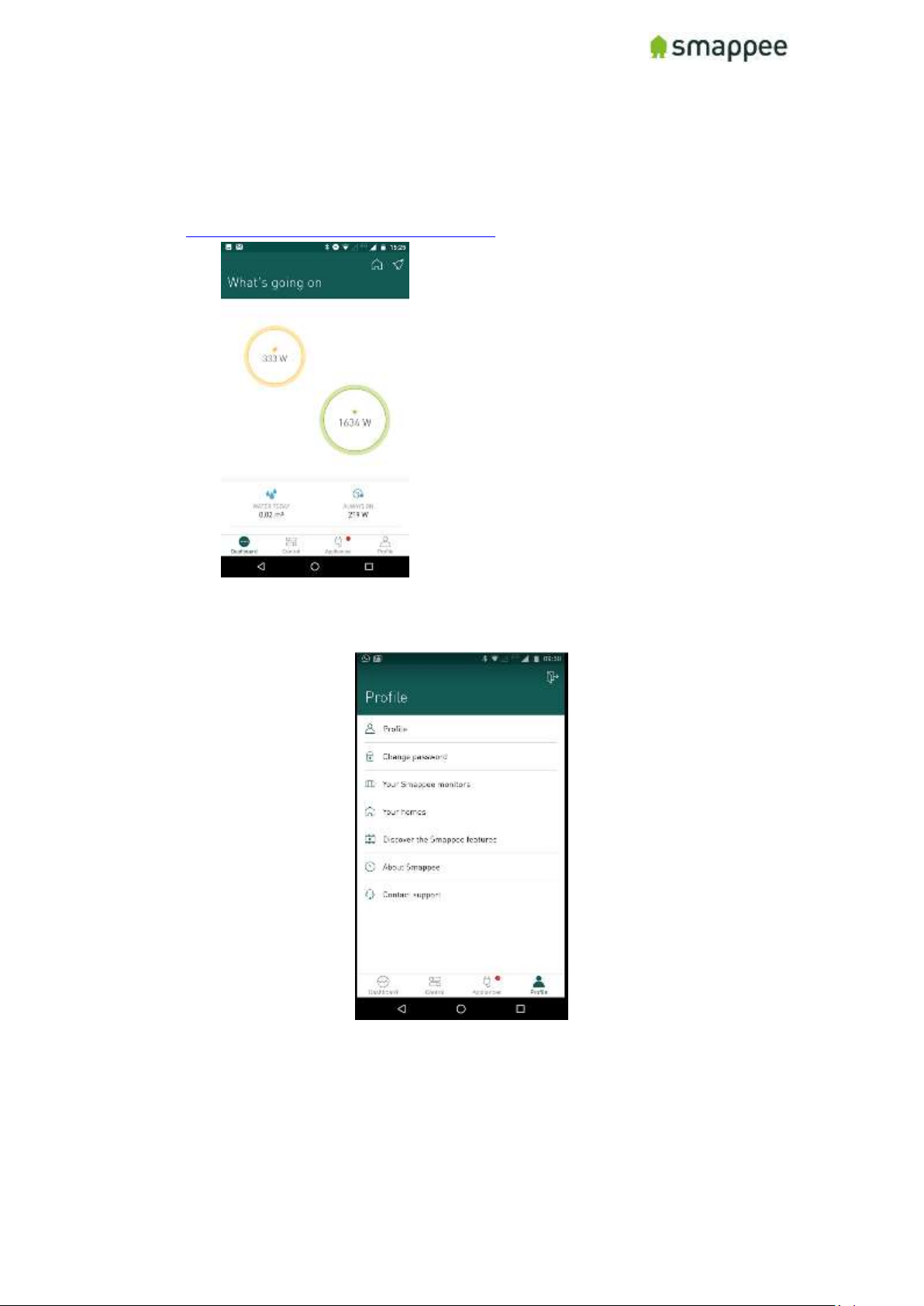
b) Save and go to Home Page
c) Verify that the bubble values on the home page of the app are accurate. Test by
plugging in a known appliance (i.e. toaster, vacuum) and watch the values on the
associated bubble increase. If the values to not appear to be accurate, visit
https://www.smappee.com/be_en/support/ for troubleshooting assistance.
d) It is always possible to check and adjust the channel configuration.
(Profile – Your Smappee Monitors - Smappee Pro – Channel Configuration)
Hint: After a channel is saved, the Active Power and Reactive Power values are viewed
in real time.
Page 42
Smappee Pro Installation and Product Manual Page 42 of 74
Version 2.0.0, 24-09-2018, rev 102
Step 11a: Final installation check-up Expert Portal
(Recommended)
Before leaving the premises, please check the following items. The preferred method is with
the Expert Portal:
1. Check Light on the Smappee → Breathing green (https://support.smappee.com/hc/en-
us/articles/203075777-What-Smappee-s-Colors-tell-you-)
2. Log in or Refresh Export Portal:
a. Click on and fill in password
b. Click on
3. In case of Wi-Fi connection problems, check the following points:
a. 2.4 GHz Wi-Fi required, preferably with automatic channel selection
b. WPA or WPA2 encryption mandatory
c. Networks without security are not supported (!)
d. SSID needs to be visible and may not be hidden during install
e. Make sure that your SSID does NOT contain one of the following characters:
é,ç,è,ä,/\, ", à î ô ï
f. Allow special characters for the Wi-Fi password: #$%@?/ \
g. Double-check your password
h. Double-check that your smart phone is connected to the correct Wi-Fi network, not
to a hotspot or other networks where you have your password configured
i. If you use WPS, check that it is active on the router
j. Make sure that MAC filtering is not active
k. Your firewall should allow Smappee to create https outbound connections (port
443)
l. Parental control also might prevent internet access based on time of day
m. The maximum number of characters for the WPA2/PSK when using an iOS device
during installation is 20.
Note: The IP address of Smappee is assigned by the DHCP of your router.
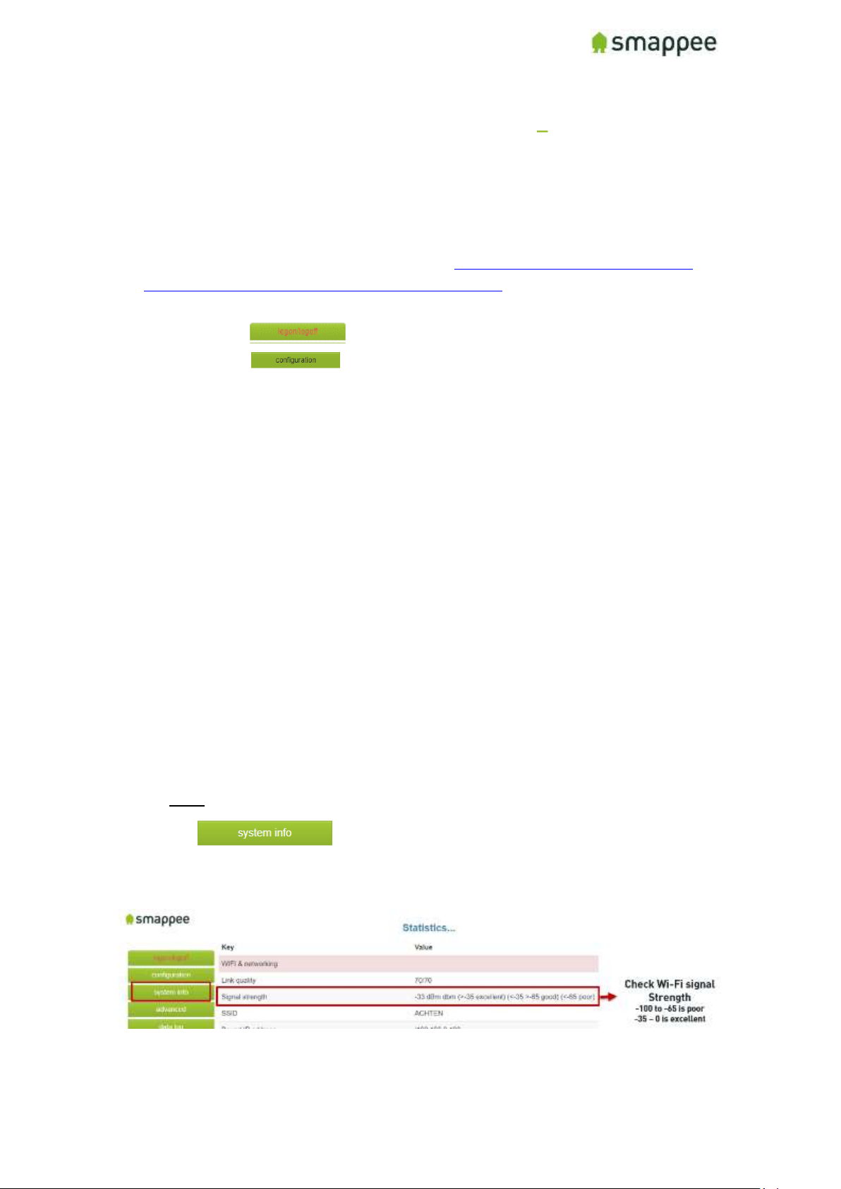
4. Click on and review the Signal strength:
a. -100 to -65 is poor
b. -65 to -35 is good (normal)
c. -35 to 0 is excellent
If the signal strength is poor, please take action in order to increase the Wi-Fi signal quality.The
value updates in real time.
Page 43
Smappee Pro Installation and Product Manual Page 43 of 74
Version 2.0.0, 24-09-2018, rev 102
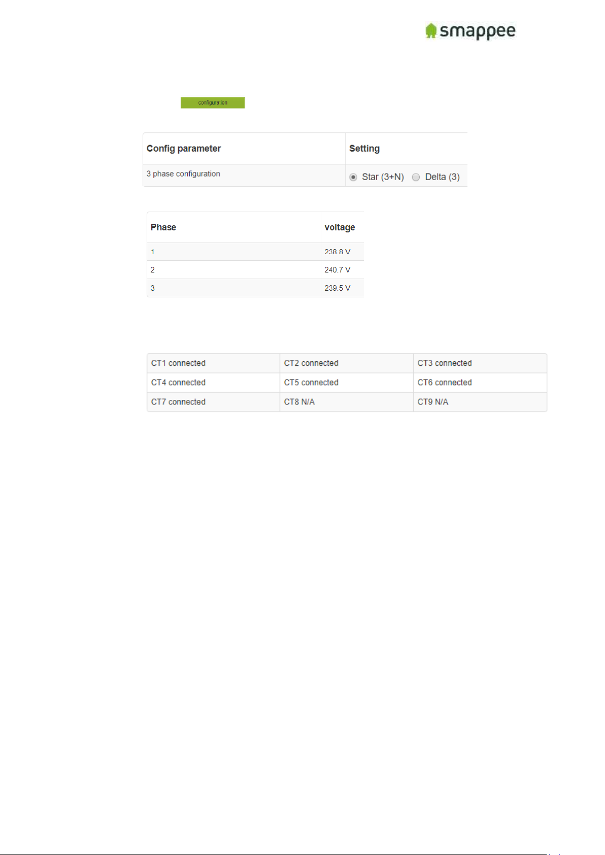
5. Review Smappee Operation
a. Click on
b. Review the Config Parameter (Star or Delta)
c. Review if voltages are displayed and correct (displayed in real-time)
measured between phase and neutral – Star & Delta = 230Volts
d. Review if all channels to that are used are displayed as ‘connected’
6. To check the phase mapping of the submetering and solar channels, engage a known
appliance in that circuit, review the channels of the submetering and solar. Validate that
the power usage increase corresponds with the power increase on Main Feeder Phase. The
phase of the submeter and solar have to correspond with main feeder phase.
Page 44
Smappee Pro Installation and Product Manual Page 44 of 74
Version 2.0.0, 24-09-2018, rev 102
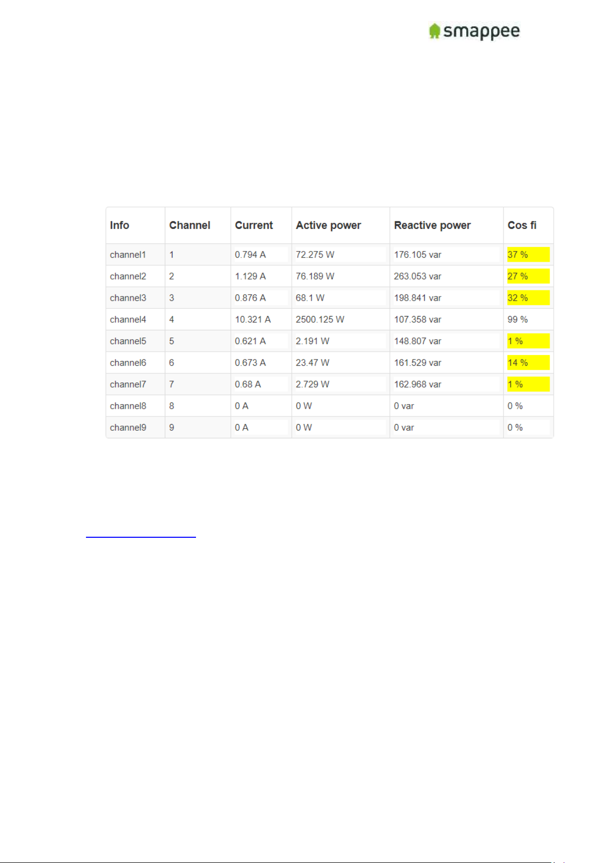
7. Check if the values consumption and production (solar) are correct. If the values look like
they are incorrect or Cos Fi is low, see point Configuration using Expert Portal - Phasemapping setup:
a. Consumption: turn high consumer appliance on and check if power increase is
correct on corresponding Main Phase and Submeter Channel.
b. Production: validate production value of solar installation with the Smappee
measurement (value could be negative when there is no sun (and production is 0)
and the inverter consumes small amount of energy.
Hint: Solar Production needs to be positive.
If needed contact support by phone (for Smappee Certified Installers) or by mail
Page 45
Smappee Pro Installation and Product Manual Page 45 of 74
Version 2.0.0, 24-09-2018, rev 102
Step 11.b: Final installation check-up Smappee app
1. Check Light on the Smappee → Breathing Green (https://support.smappee.com/hc/en-
us/articles/203075777-What-Smappee-s-Colors-tell-you-)
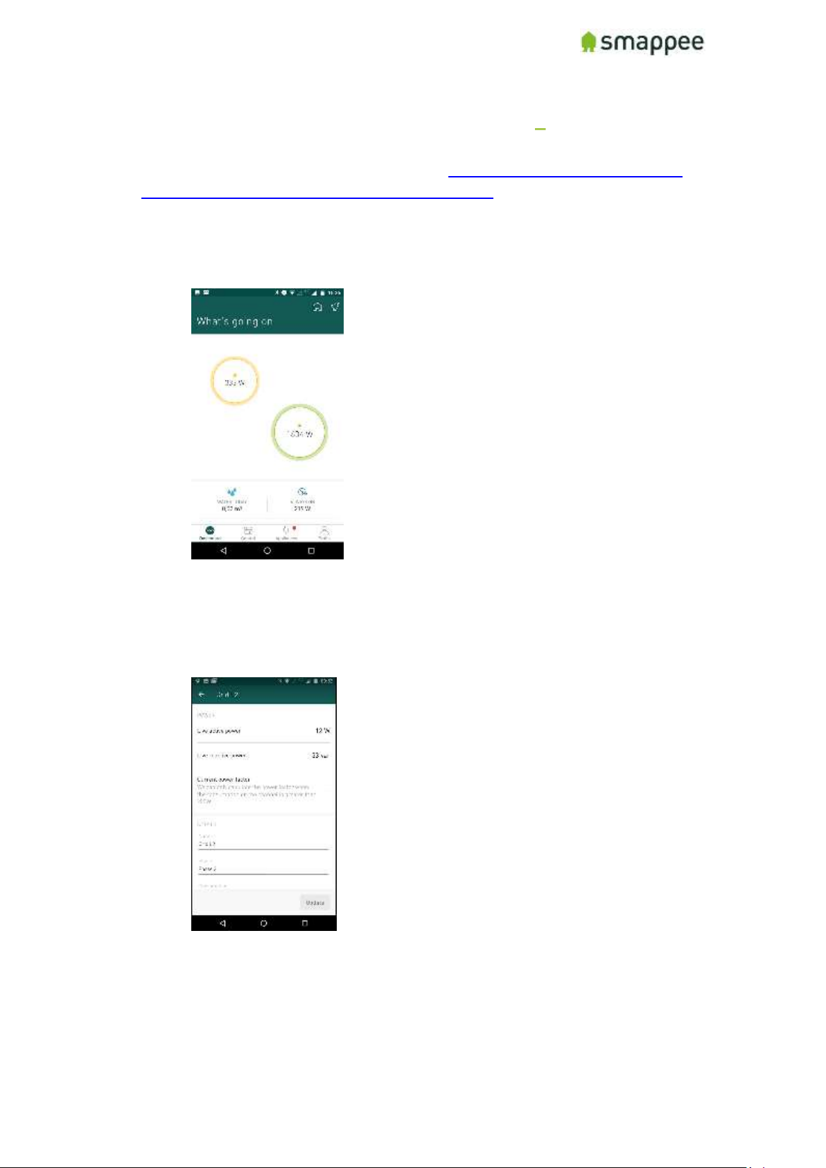
2. Go to Home Screen of the app are updated (Grey is Consumption, Green is Production).
a. Verify that the bubble values on the home page of the app are accurate. Test by
plugging in a known appliance (ie toaster, vacuum) and watch the values on the
associated bubble increase.
3. Check Phase Mapping of the submetering channels:
a. Go the Channel Configuration window and check if the power values of the
submetering channel phase indication corresponds with the main feeder phase
number. The channel of the Submeter needs to correspond with the Main Feeder
Phase on which the power increase takes place.
If needed contact support by phone (for Smappee Certified Installers) or by mail
[email protected]
Page 46
Smappee Pro Installation and Product Manual Page 46 of 74
Version 2.0.0, 24-09-2018, rev 102
Step 12 (Optional): Share Smappee with other
Smappee user
A Smappee monitor can be shared with multiple Smappee user accounts.
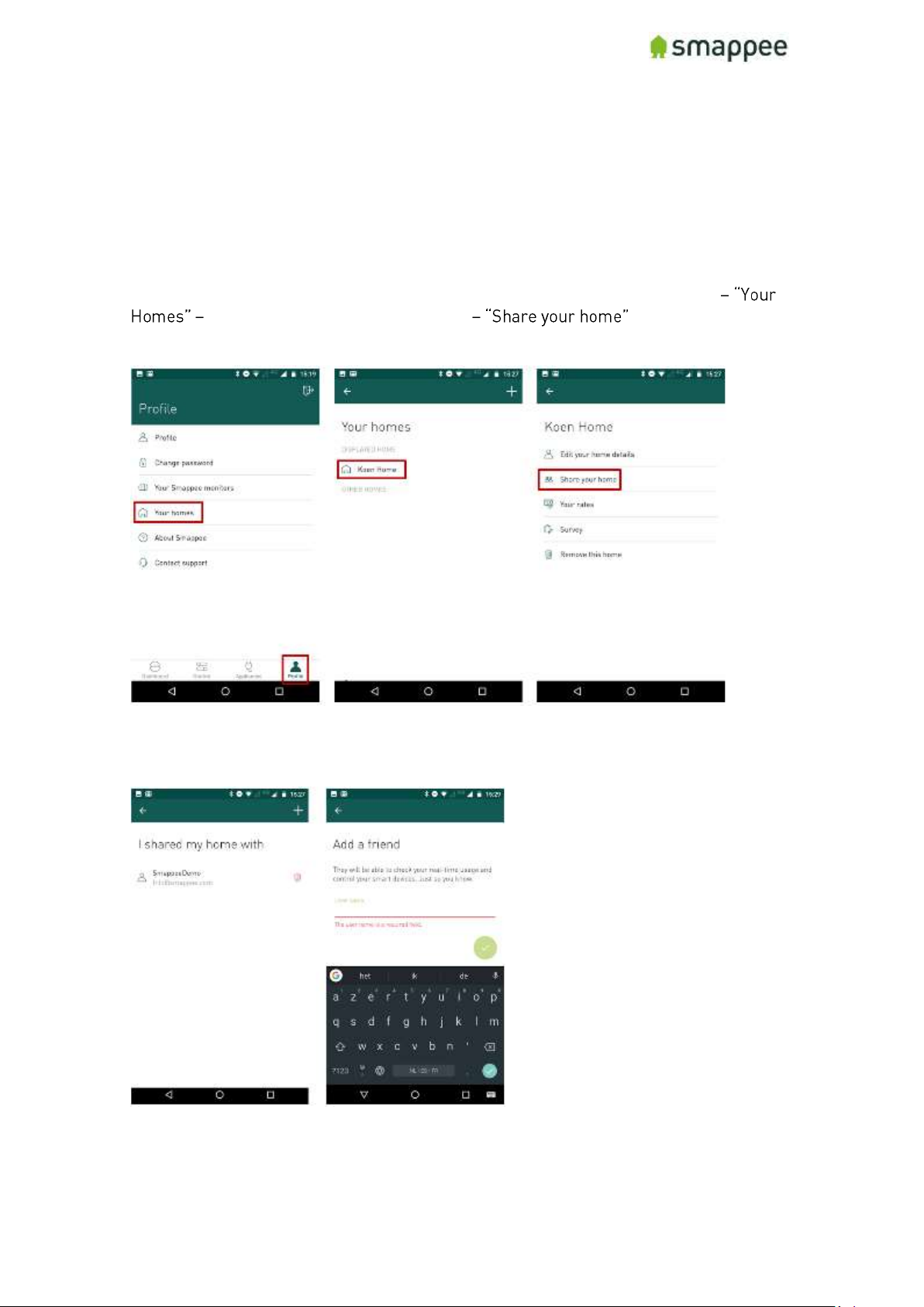
Starting at the home page, expand dropdown menu (top left) - Select "Profile"
select the home you want to share :
Add a new user (friend) using his email address attached to his Smappee Account and select
"Done" to complete. Make sure the person you are trying to share the data with already has a
Smappee account.
Page 47
Smappee Pro Installation and Product Manual Page 47 of 74
Version 2.0.0, 24-09-2018, rev 102
How to install multiple Smappee monitors under 1
user account
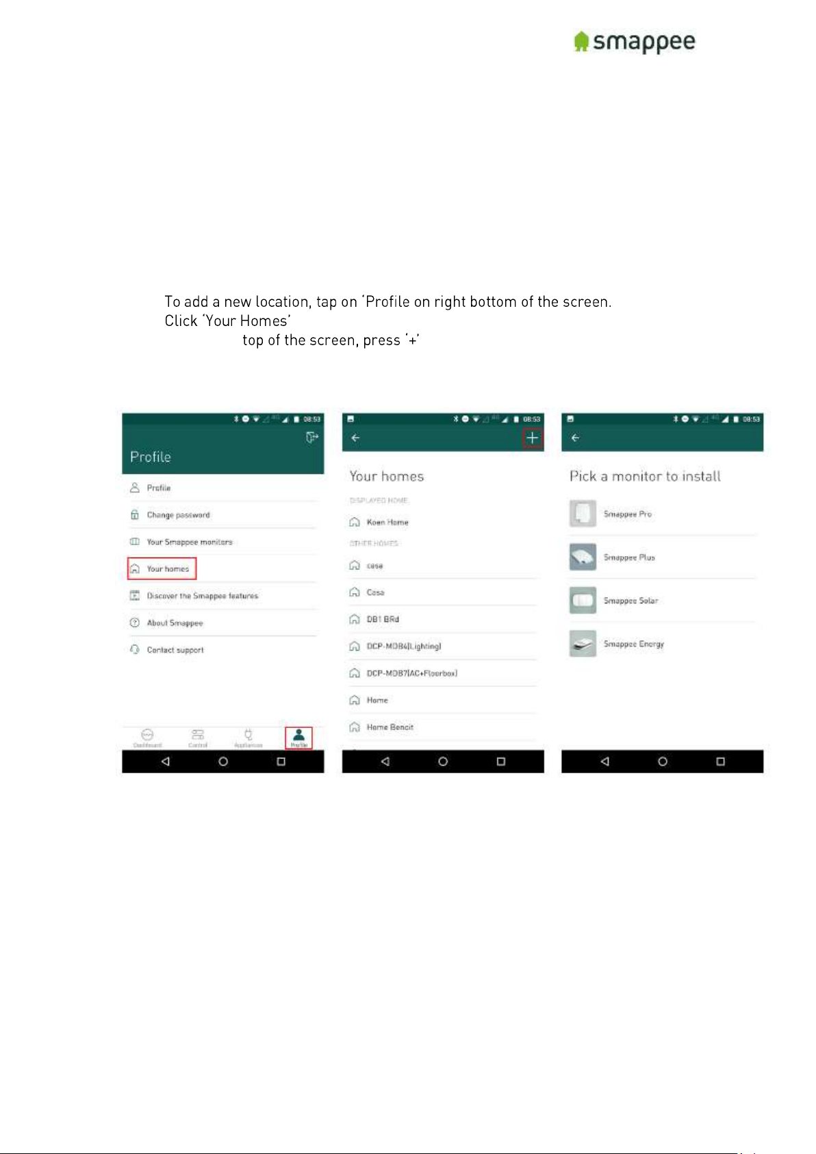
To install multiple Smappees on one account, you will need to create an additional
(new- home for each Smappee. This means that you will have access to all these homes
(locations) by logging into that one account.
Process
•
•
• At the right
• Follow the installation process
Page 48

Smappee Pro Installation and Product Manual Page 48 of 74
Version 2.0.0, 24-09-2018, rev 102
Smappee Product Manual
This part of the document explains the detailed features of the product that are needed
to install the device.
Page 49
Smappee Pro Installation and Product Manual Page 49 of 74
Version 2.0.0, 24-09-2018, rev 102
The connectors and Inputs of the Smappee
Overview
This section explains the connectors of the Smappee Pro.
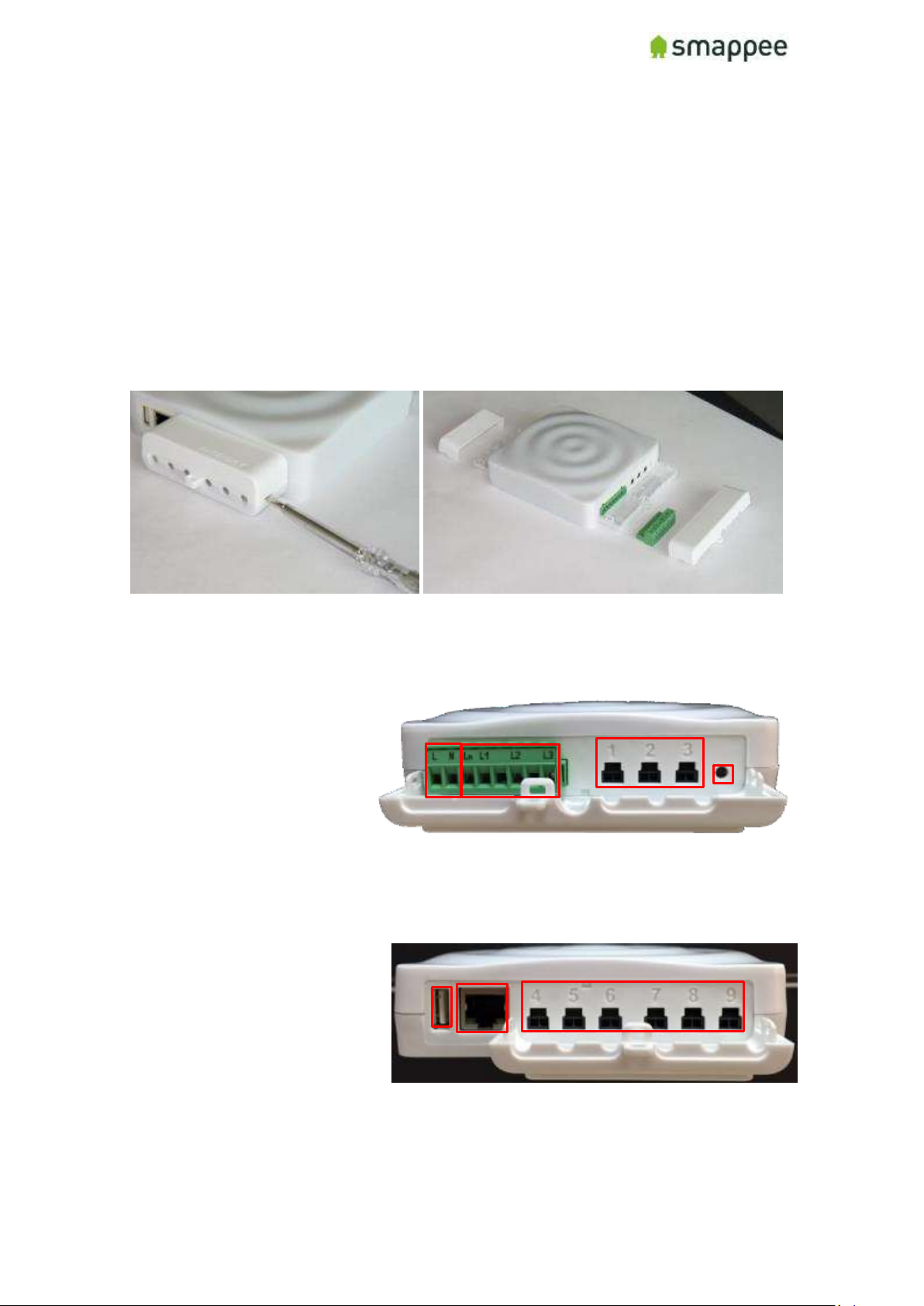
Accessing the Connectors
To get full access to all connectors of the Smappee monitor, you should remove the two
covers.
For removing the covers, insert a screwdriver at the sides of the covers and carefully
pull up the cover.
Connectors at the Front
The picture shows the connectors at the front.
• Power supply
• Voltage terminal
• CT connectors 1 to 3
• Reset button
Connectors at the Back
The picture shows the connectors at the back.
• USB port
• Ethernet port (LAN)
• CT connectors 4 to 9
Page 50
Smappee Pro Installation and Product Manual Page 50 of 74
Version 2.0.0, 24-09-2018, rev 102
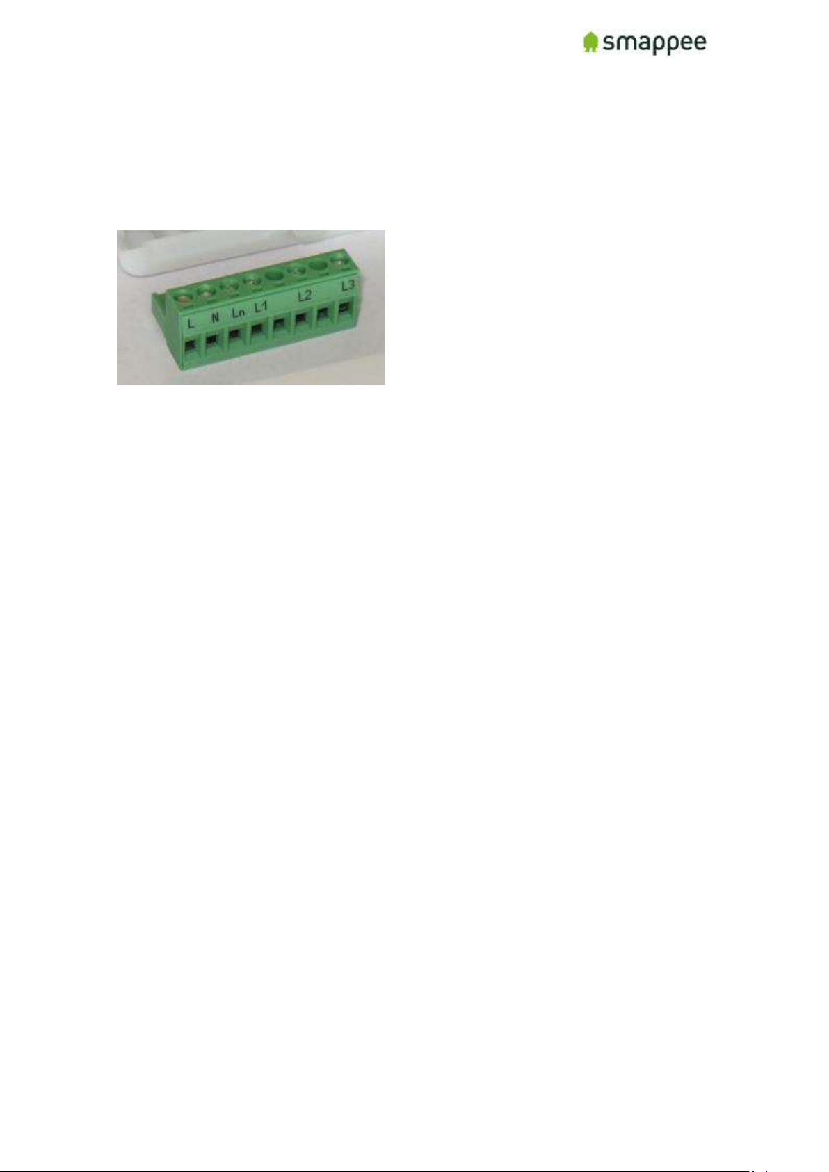
The Green 8-Pin Connector Block
The Smappee is delivered with a green 8-Pin connector block.
It is used to:
• connect the Smappee power supply
• measure the voltage of the power phases
You can find more details in the following sections.
Page 51
Smappee Pro Installation and Product Manual Page 51 of 74
Version 2.0.0, 24-09-2018, rev 102
Connecting the Power Supply
Overview
The Smappee is powered by the green 8-pin connector block.
Important: Always turn the main power off before performing the next steps!
Do NOT power-on the Smappee unless this manual specifically asks you to do so.
Connecting the wires
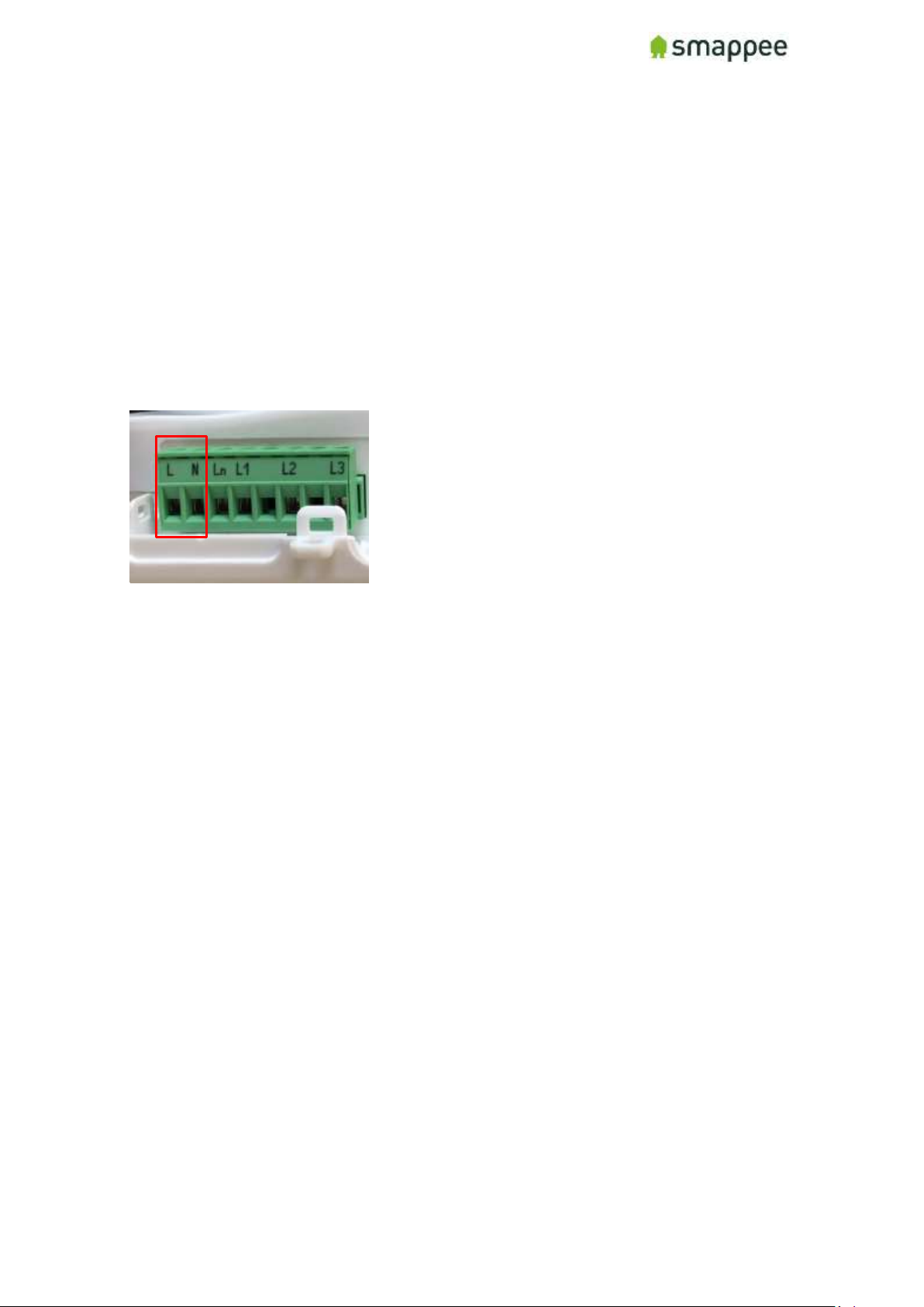
Instructions:
1. Connect the Phase wire of the power supply to the connector marked L.
2. Connect the Neutral of the power supply to the connector marked N.
Important Requirements
Important requirements for the installation:
• The voltage of the power circuit should be in the range of 100-240 Vrms.
• A circuit breaker should always be used for the power supply. The circuit
breaker should be located close to the monitor and be easily reachable.
• The circuit breaker should always be the disconnecting device for the Smappee
monitor.
• All wires used should have a diameter between 0.75 and 2.5mm².
• Note: None of the power connectors are used for any type of measurement.
Remember
Do NOT power-on the Smappee yet. This manual will specifically ask you to
power-on the Smappee in one of the installation steps later on.
Page 52
Smappee Pro Installation and Product Manual Page 52 of 74
Version 2.0.0, 24-09-2018, rev 102
Connecting the Voltage Measurement Wires
Overview!
Smappee measures the various voltages and phases of the individual Phase wires and
the Neutral wire of the electrical installation. These wires need to be connected to the
inputs of the green 8-pin connector block.
This section explains how to connect the measured wires to the respective inputs of the
connector block.
Separated Power Supply
Please be aware that the measurement lines are fully separated from the lines of the
power supply. Consequently, the power lines may be connected to circuits on an UPS
or any other source without impacting the measurements.
However, this also results in the need to connect all lines to the measurement inputs.
This is particularly true for the input Ln, which always needs to be connected to the
Neutral line.
Inputs for Phase and Neutral
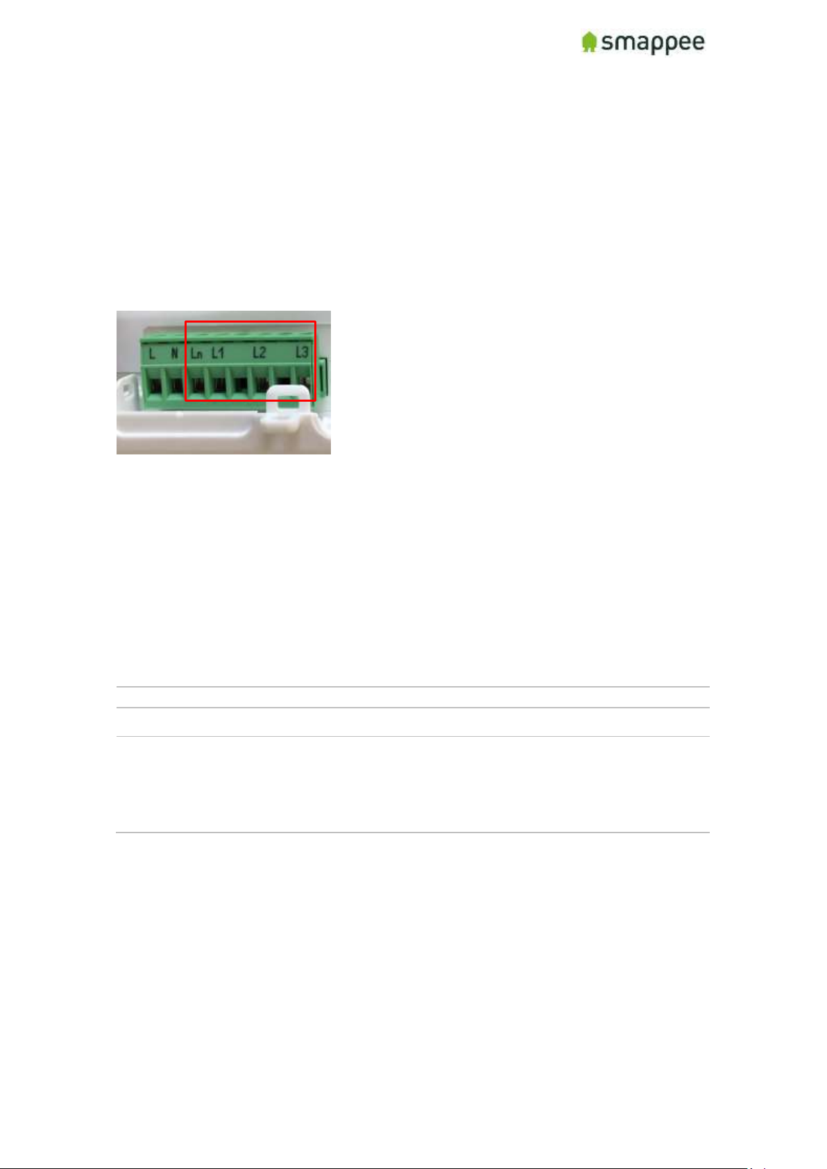
There are four inputs:
Input
Description
L1 - L3
Measurement inputs for the voltage and phase of each phase wire.
Ln
Measurement input for the Neutral reference.
Note: To measure the Neutral reference correctly, always connect
the Input Ln explicitly to the Neutral wire. There is NO internal link
with the Neutral line of the main power supply.
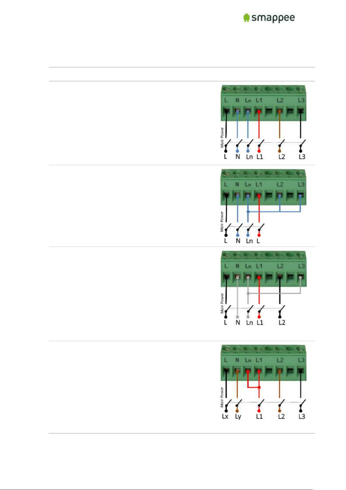
Installation Variants
The wiring of the voltage measurement inputs on the green 8-pin connector block
depends on the type of electrical installation.
There are four different Installation Variants:
• Three-phase with Neutral ("Star")
• Single phase
• US Split phase (180°)
• Three-phase without Neutral ("Delta")
On the next page, you find detailed instructions for the wiring.
Page 53
Smappee Pro Installation and Product Manual Page 53 of 74
Version 2.0.0, 24-09-2018, rev 102
Installation Variants
The table below shows the wiring for the various installation variants.
Installation Variant
Wiring Schema
Three-Phase with Neutral ("Star")
4. Identify the three phase cables L1, L2 and L3
as well as the Neutral cable.
5. Connect the Neutral to the Ln.
6. Connect the phase cables to the correct input
of the voltage measure terminal:
• Phase cable L1 to input L1
• Phase cable L2 to input L2
• Phase cable L3 to input L3
Single Phase
3. Identify the phase cable L1 and the Neutral
cable.
4. Connect the Neutral cable to the Ln, L2 and
L3 input.
5. Connect the phase cable L1 to the L1 input.
US Split phase (180°)
1. Identify the two phase wires L1 and L2 and the
Neutral wire.
2. Connect the Neutral wire to the Ln and L3
connector of the voltage measure terminal.
3. Connect the phase cables to the corresponding
inputs:
• Phase cable L1 to the connector L1
• Phase cable L2 to the connector L2
Three-Phase Without Neutral ("Delta")
4. Identify the three phase cables L1, L2 and L3.
5. Connect the first phase cable L1 to the
Neutral input Ln.
6. Then connect the phase cables to the
corresponding connectors of the voltage
measure terminal:
• Phase cable L1 to the input L1
• Phase cable L2 to the input L2
• Phase cable L3 to the input L3
Page 54

Smappee Pro Installation and Product Manual Page 54 of 74
Version 2.0.0, 24-09-2018, rev 102
Verify the Correctness of Installation
After finalizing the full Smappee installation, and while testing the Smappee
measurements, you should specifically verify the correct wiring of the 8-pin connector
block.
These checks will be explained at a later step during the installation, at section
"Checklist for Correct Configuration", on page 70.
Page 55
Smappee Pro Installation and Product Manual Page 55 of 74
Version 2.0.0, 24-09-2018, rev 102
Connecting the Current Transformers ( )
Overview
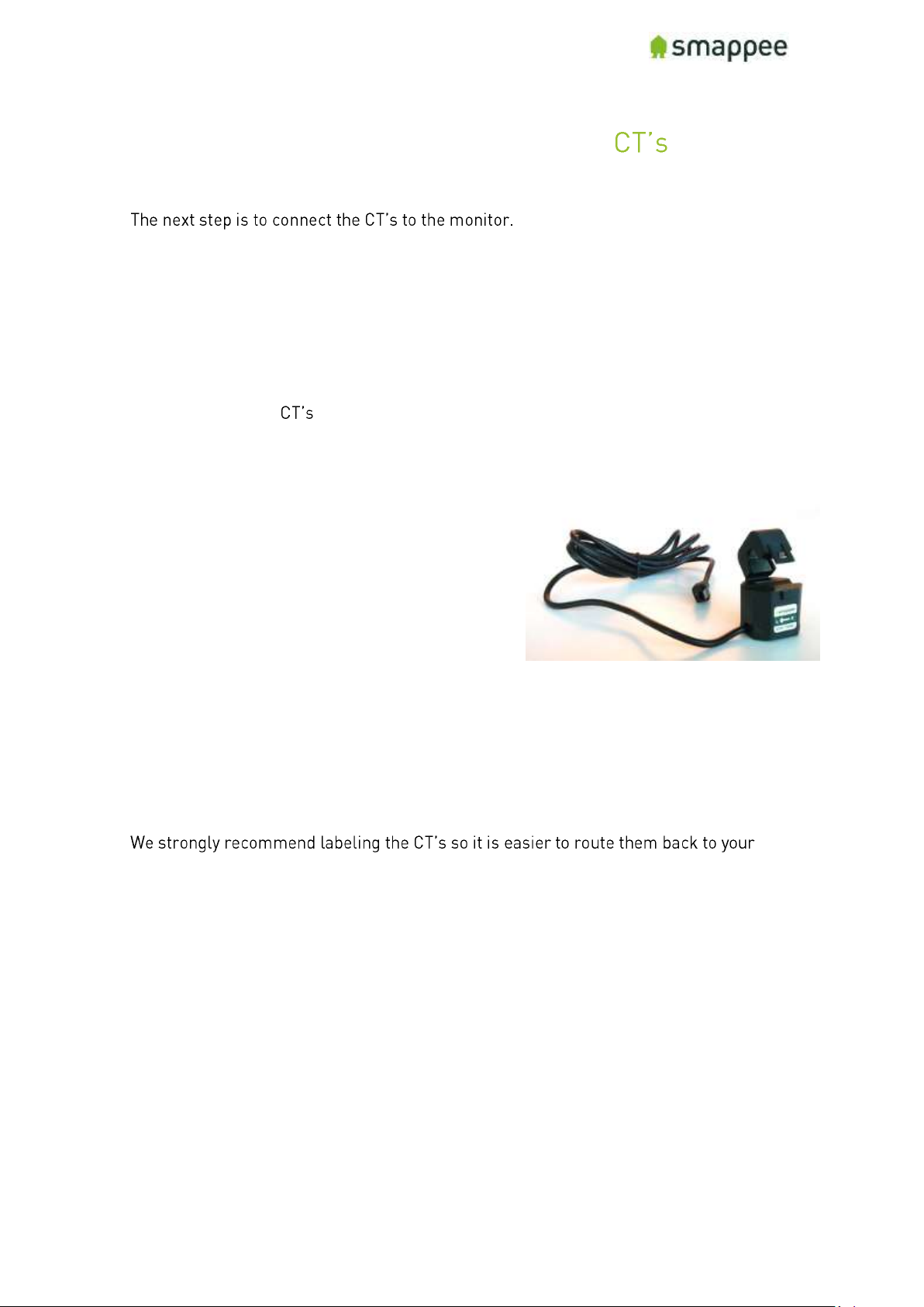
Each current transformer (CT) consists of a sensor and a plug. The sensor needs to be
attached on the cable and the plug needs to be inserted in one of the Inputs 1-9 of the
Smappee monitor.
Please note that each CT has an arrow inside. The correct direction of the arrow is very
important when installing the CT.
Configuration
The newly installed always require an update of the configuration pages of the
Smappee.
For details, please see section "Configure the Current Transformers" on page 64.
Technical details
The Smappee Pro has inputs for 9 current
transformers.
The transformers are available in different sizes.
For all the different sizes, please see section
"Current Transformer Variants" on page 56.
Instructions
First, start by attaching the Current Transformers (CT) around the cables you wish to
measure. (These can be main incoming cables, sub-feeds, feeds from solar, etc.), just
put the CT around the cable and then close it.
Important: Pay attention to the direction of the arrow on the CT. The arrow always
points towards the electrical load, i.e. in the direction of the energy flow.
monitor afterwards (for example oven phase 1). Once the current transformers have
been installed around the cables, now route them back to the Smappee Pro.
Rogowski Coils
The Rogowski coils can only be used with the Smappee Pro.
A Rogowski coil is a special accessory that is reserved for very specific use cases. For
more details on Rogowski coils, please refer to section "Special Cases - Rogowski
Coils", on page 69.
Page 56
Smappee Pro Installation and Product Manual Page 56 of 74
Version 2.0.0, 24-09-2018, rev 102
Current Transformer Variants
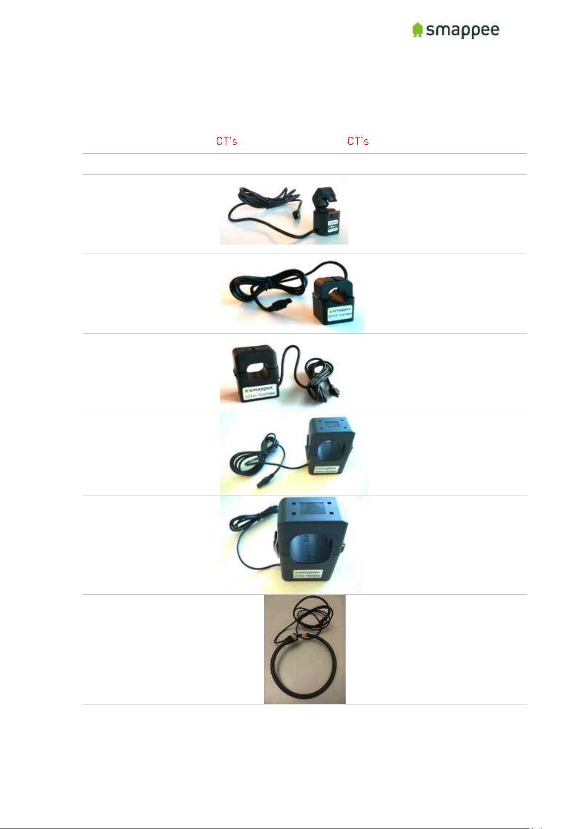
The table shows the current transformers that can be used with the Smappee Pro.
Smappee supports only the listed below. No other should be used!
Name/type
Picture
Specs
Current Transformer
50A
MC: 50A
MAX OV : 333 mV
MAX cable Ø: 10 mm
(0.39 in)
Current Transformer
100A
MC: 100A
MAX OV : 666 mV
MAX cable Ø: 16mm,
(0.63 in)
Current Transformer
200A
MC: 200A
MAX OV : 1332 mV
MAX cable Ø: 24mm,
(0.94 in)
Current Transformer
400A
(*Pro Only)
MC: 400A
MAX OV : 666 mV
MAX cable Ø: 36mm,
(1.41 in)
Current Transformer
800A
(*Pro Only)
MC: 800A
MAX OV : 1332 mV
MAX cable DIA: 50mm,
(1.96 in)
Rogowski Coil
1000A
(*Pro Only)
MC: 1000A
MAX OV : 166,666666 mV
MAX cable DIA: 120mm,
(4,72 in)
Page 57
Smappee Pro Installation and Product Manual Page 57 of 74
Version 2.0.0, 24-09-2018, rev 102
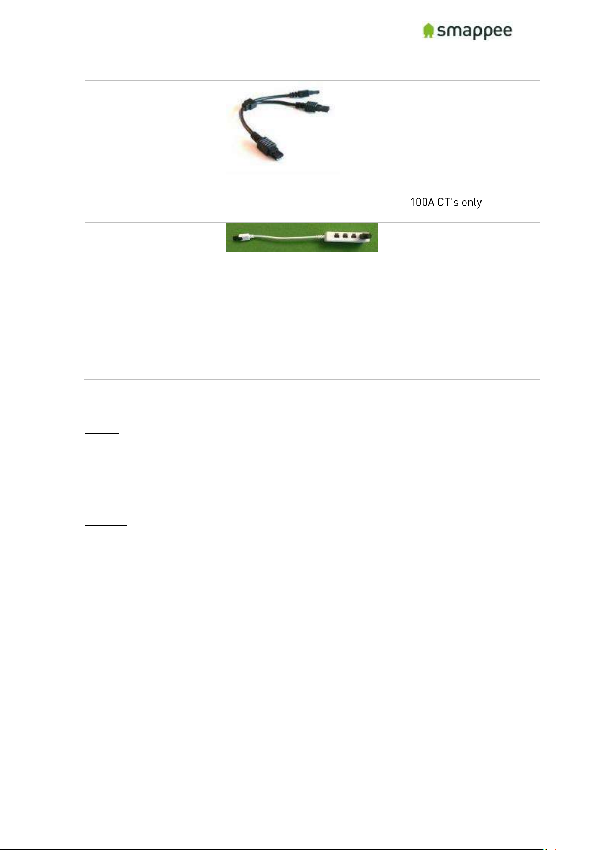
Y-cable
AC-YC
Y-cable for combining
two current
transformers (CT)
measuring on the same
phase. Measurements
will be summed up and
reported as one value.
Compatible with 50A and
CT-Extender
AC-EXT-4
(comes with 3x 50A CT)
Extension unit for
combining up to 4x 50A
transformers (CT)
measuring on the same
phase.
Measurements will be
summed up and reported
as one value.
Compatible with 50A CT
only
The length of a CT cable is 1.5 m (4.9 ft).
Notes:
• Current transformer types can mixed on a Smappee Pro (except for Rogowksi coil)
• Different current transformer (standard and Rogowski) types can be mixed on a Smappee
Pro. There are exceptions depending on the setup. See section "Special Cases - Rogowski
Coils" for more details.
Legend:
(* Pro Only) Can only be used with the Smappee PRO. Contact Smappee Sales if you consider using this item.
MC: maximum current
MAX OV: Maximum output voltage
MAX cable Ø: Maximum phase cable diameter
Page 58
Smappee Pro Installation and Product Manual Page 58 of 74
Version 2.0.0, 24-09-2018, rev 102
Preparing the Internet Connection
Overview
Now you should choose the method to connect the Smappee to the internet. There are
three alternative connection methods available:
• Ethernet cable (recommended)
• external Wi-Fi USB module
• external 3G/4G internet USB dongle
This section will prepare the Smappee for connecting to the Internet at a later point
during the installation steps.
Important: You can only use the modules that are supplied by Smappee. Other
devices are not supported.
NO Hot-Plugging
All network cables and dongles need to be inserted or removed while the power is
OFF.
Ethernet cable (recommended)
The Smappee Pro monitor should be connected to the network by an RJ-45 Ethernet
cable.
The Ethernet cable should be connected to the Ethernet port of your monitor. When
using Ethernet, you should not connect a USB Wi-Fi or 4G dongle.
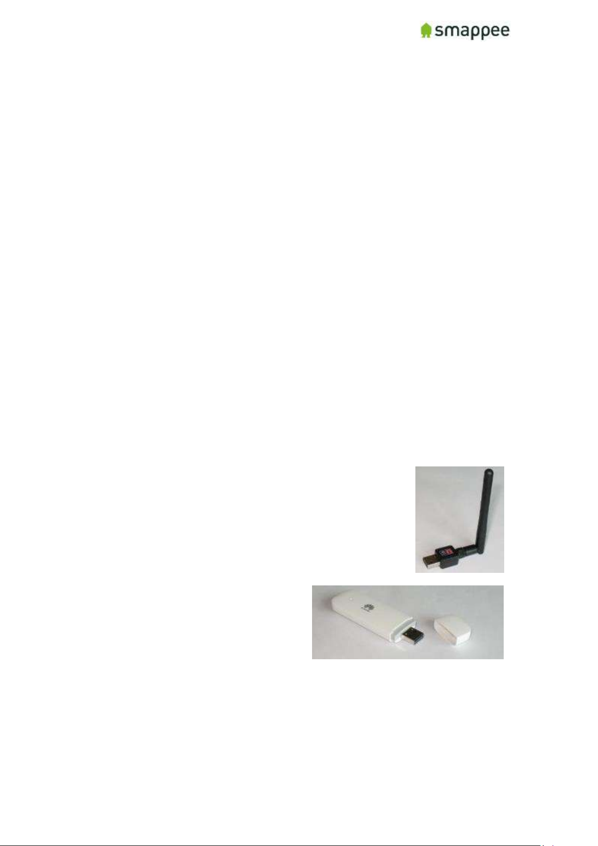
External Wi-Fi module (USB)
The external Wi-Fi module connects the Smappee Pro to a local
Wi-Fi network. It should be plugged in the USB port of the
Smappee.
If you experience problems with the Wi-Fi connectivity, please
consult the Wi-Fi checklist. You can find the checklist at
http://support.smappee.com. Search for "checklist".
External 3G/4G Dongle (USB)
The external 3G/4G dongle directly connects
your Smappee monitor to the internet
through an 3G/4G connection.
Smappee ships the dongle preconfigured
with a SIM card, as part of your data
subscription option.
Please note this device requires a stable 3G/4G network signal. Please check this
before buying this device.
Connect the cable or USB module
Once you have selected the connection method, please insert the selected cable or
module in the respective Smappee port, while the Smappee is still turned off.
Page 59
Smappee Pro Installation and Product Manual Page 59 of 74
Version 2.0.0, 24-09-2018, rev 102
Initial Power-On of the Smappee Monitor
Introduction
Your Smappee Pro monitor is now nearly ready for the first power-on. Please complete
a number of checks, before you power-on the Smappee.
Important: The Smappee Pro is not yet completely installed and insulated.
Perform the actions of section "Mounting and Enclosing", on page 72, before
leaving the installation place.
Check Before First Power-On
Please do a final check:
ID
Check
More info
1.
Smappee is connected by a circuit breaker.
page 51
2.
The 8-pin connector block is correctly wired for both the main
power supply as well as the measuring wires.
page 52
3.
The current transformers are connected at your electrical
installation and to the inputs at the Smappee.
page 55
4.
The hardware for the network (Ethernet cable or USB dongle)
is connected to the Smappee.
page 58
5.
You understand that the Smappee Pro is not yet completely
installed and properly insulated. Do not leave the place of
installation before completing the installation.
page 72
Power On
Now use the circuit breaker to turn on the power.
Lights for Network Status
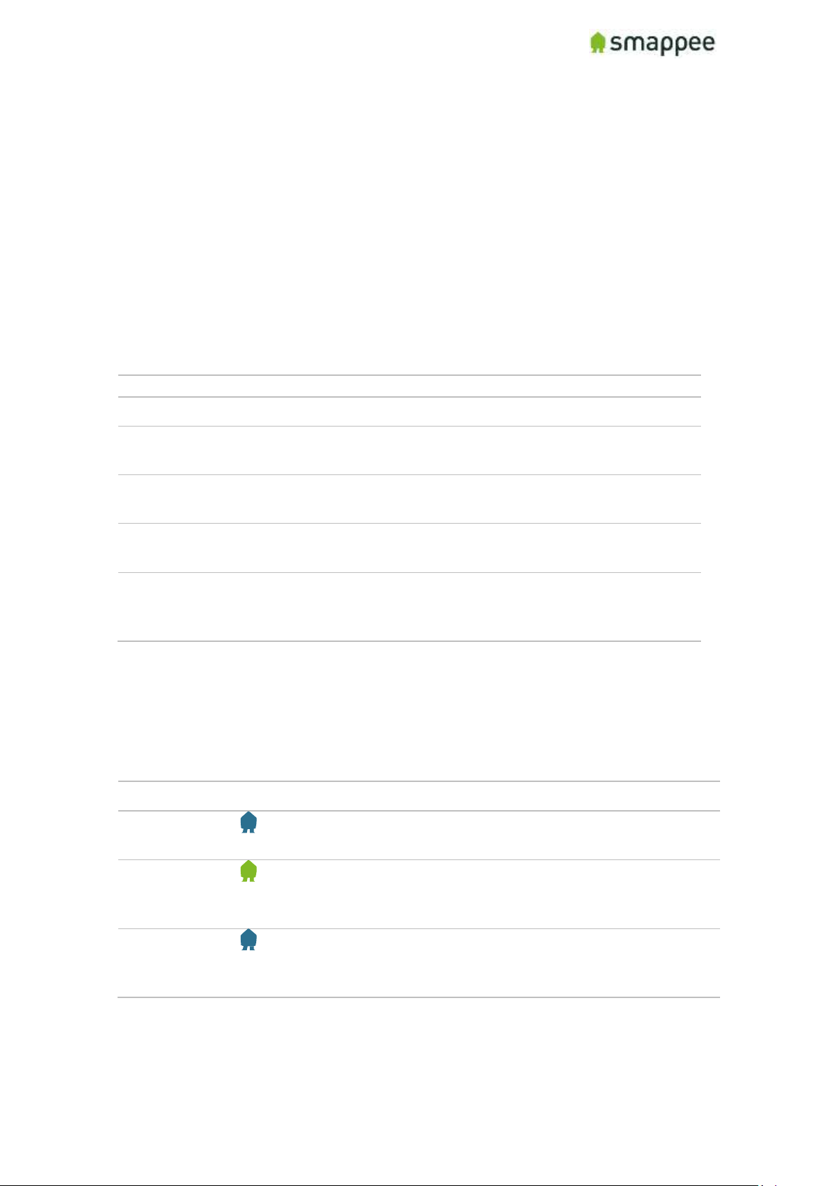
Smappee indicates the progress of the power-on and the network status by the light.
Light
Description
Blue Steady
The Smappee is powering on. Please wait for about 3 minutes.
Hint: The light may briefly go dark during that time.
Green Steady
The Smappee is connected to the local network and ready to be
installed by the App. The Smappee should show this color when
it is connected by Ethernet or a 3G/4G dongle.
Blue Flashing
The Smappee monitor is ready to be connected to the local
network and to be installed by the App. The Smappee should
show this color when it is connected by a Wi-Fi dongle.
If you see one of these colors, proceed to the next page of this manual.
If, however, Smappee shows a different color, please refer to section "Troubleshooting
Internet and Cloud Access" on page 62.
Smappee Pro Installation and Product Manual Page 60 of 74
Page 60

Version 2.0.0, 24-09-2018, rev 102
Working with Multiple Sites
Overview
Large multi-site businesses may wish to work with multiple Smappee devices that are
installed on multiple locations.
Similarly, an installer may wish to install multiple Smappee devices at different sites of
different customers.
In addition, there may be multiple user accounts that need to get shared access to the
data.
This section explains how to use the app in these scenarios.
Important
If you install a new Smappee device in an environment with multiple sites or multiple
users, make sure that you are logged in with the correct user name. Also make sure,
that you have activated the correct service location.
Watch out! If you use the wrong user name or service location, you may corrupt
the new and the existing installations.
Understanding Service Locations
For understanding the multi-site installations, you need to understand the concept of
Service Location.
The Service Location represents the place that is measured by a Smappee. In most
cases, the Service Location is identical with the house or site that is connected to a
particular utility electricity meter.
Basic Principles
The multi-site, multi-user configurations follow these principles:
Measurements
• When measuring, a Smappee device is always connected to a single service
location.
• All measurements (consumption etc.) are linked to a particular service location.
User Access
• For viewing and modifying the data of a service location, you need to have a user
login (user name + password) with access rights to that service location.
• When you create a new service location (during installation) your user login
automatically has access to that service location.
• You may share the access rights of your service locations with other users.
They then have the same access rights as you have.
• A user may have access to multiple service locations.
Replace Hardware
• Consequently, when replacing a defect Smappee with a new device, the service
location remains the same. Thus, the new device gets connected to the same
service location. All previous and new measurements remain available at the
service location.
Page 61
Smappee Pro Installation and Product Manual Page 61 of 74
Version 2.0.0, 24-09-2018, rev 102
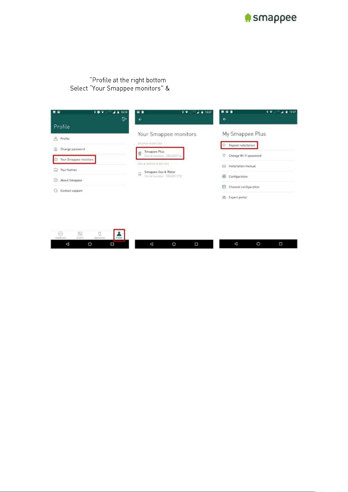
Starting the Installation of a Replacement Device
In the special case that you want to install a new device to replace an (defective)
Smappee follow these steps.
1. Select
2. Smappee Pro
3. Select "Repeat installation"
Page 62
Smappee Pro Installation and Product Manual Page 62 of 74
Version 2.0.0, 24-09-2018, rev 102
Troubleshooting Internet and Cloud Access
Introduction
This section provides help in case of problems during the connection step.
Note: The connection to the Internet and the Cloud needs to be fully functional before
you can continue the installation (i.e. configuring the Smappee for accurate
measurement).
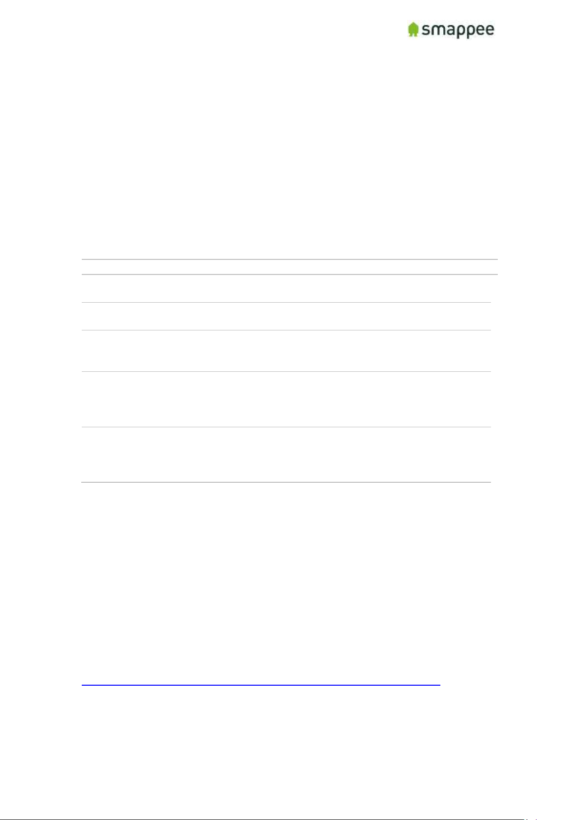
Understanding the milestones
The connection to the Internet and Cloud has the following main milestones. Please
refer to them in case of problems.
Step
Milestone
Success Indicator
1.
Connect to Wi-Fi network (if applicable) and/or local
network.
Green steady light
2.
Smappee contacts the Smappee cloud.
-
3.
The App and the Smappee monitor "meet" in the cloud
and connect to each other.
App shows screen
with "jumping"
Smappee logo
4.
The Smappee monitor starts measuring the power
signals (even if the configuration is not yet correct). It
is important that at least one current transformer is
connected.
-
5.
The App receives real-time measurements from the
monitor and displays them in the main screen.
Note: The actual values are not yet necessarily
correct.
Some values in the
App main screen,
like "1 W"
Issues with Local Network (Ethernet or Wi-Fi)
If your Smappee Pro is connected by Ethernet or Wi-Fi make sure that the site system
administrator is aware of the installation. They may need to change settings in the
network and firewalls.
Hint: Experience shows that you should contact the IT responsible of the installation
site long before the installation date.
Wi-Fi Checklist
If you experience problems with the Wi-Fi connectivity, please consult the Wi-Fi
checklist. You can find the checklist at http://support.smappee.com. Search for
"checklist".
https://support.smappee.com/hc/en-us/articles/201618739-Wi-Fi-checklist
Remember: The dongle needs to be inserted BEFORE you power-on the Smappee Pro.
Page 63
Smappee Pro Installation and Product Manual Page 63 of 74
Version 2.0.0, 24-09-2018, rev 102
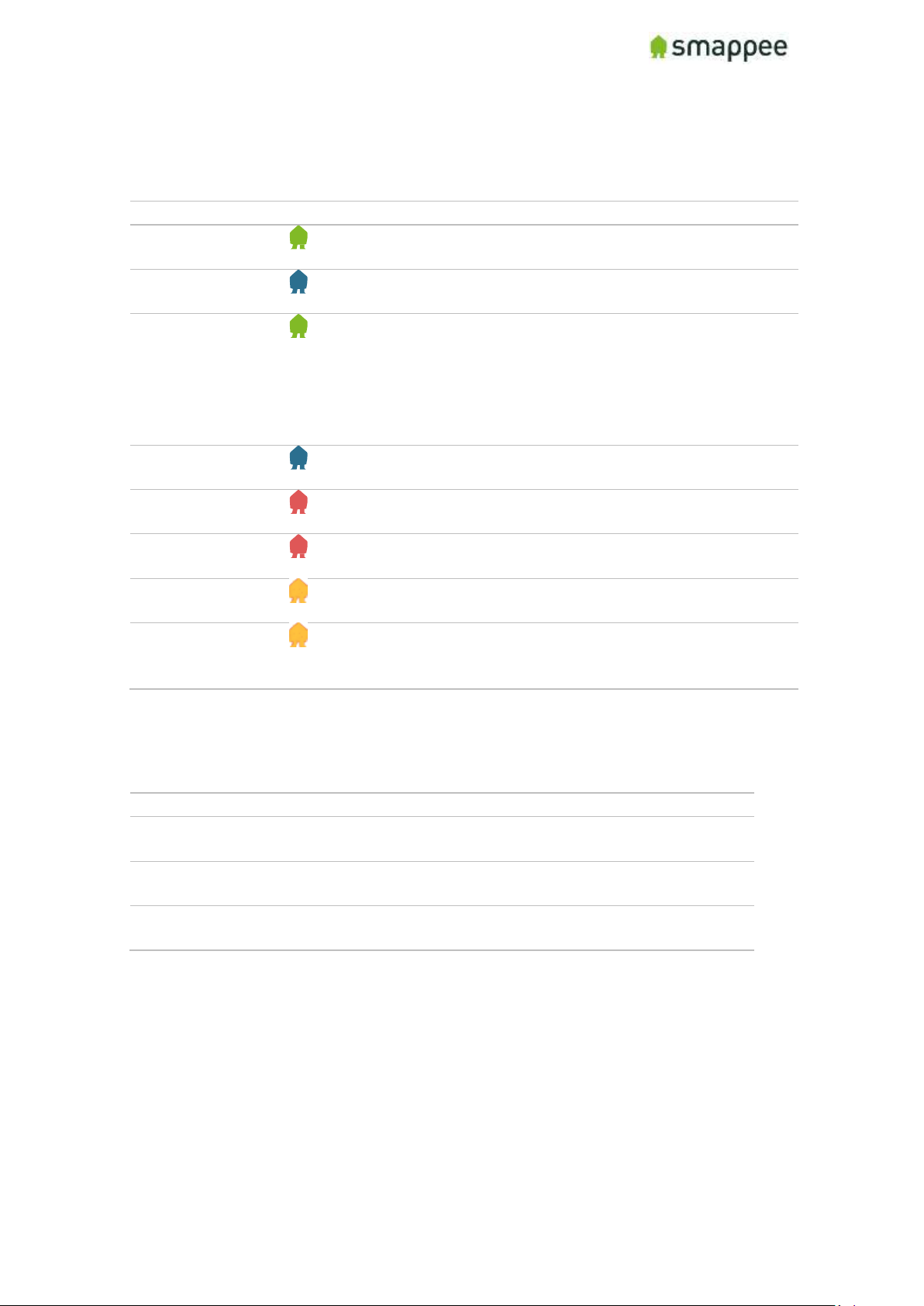
Colors of the Smappee Light
The table below provides an overview over all colors that may be shown during the
installation.
Color
Description
Green Breathing
All good. The monitor is working correctly. You can continue
the next steps for installation and configuration.
Blue Steady
The monitor is starting up. This may take up to 3 minutes.
The light may briefly go dark during that time.
Green Steady
Network connectivity successful, but Smappee not yet
connected to a user account.
• Ethernet: Connected to the local network.
• Wi-Fi: Connected to the Wi-Fi and the local network
(i.e. the Wi-Fi password is correct)
• 4G dongle: Connected to the 4G network.
Blue Flashing
The monitor is ready to be connected to the local Wi-Fi
network and to be installed on the App.
Red Steady
The monitor is missing connectivity with internet during
startup. Connection issue.
Red Flashing
The monitor had a previous working internet connection but
has now lost connectivity to the internet.
Orange Steady
The Wi-Fi hotspot access point has been activated, in order
to allow the Smappee to receive a new Wi-Fi password.
Orange Flashing
Smappee is trying to open an Wi-Fi hotspot access point.
Please wait a few seconds. The light will turn Orange Steady
in a few moments.
Colors of 4G dongle
If your Smappee Pro is connected by 4G dongle, please check the colors of the dongle.
Color
Description
Any steady
(Blue, Green, Cyan)
Successfully connected. The dongle is successfully
connected to the cellular network.
Any slow blinking
(Blue, Green, Cyan)
The dongle is registering with a cellular network.
Green fast blinking
(1 per second)
Stick is powered on. No connection.
Remember: The dongle needs to be inserted BEFORE you power-on the Smappee Pro.
Page 64
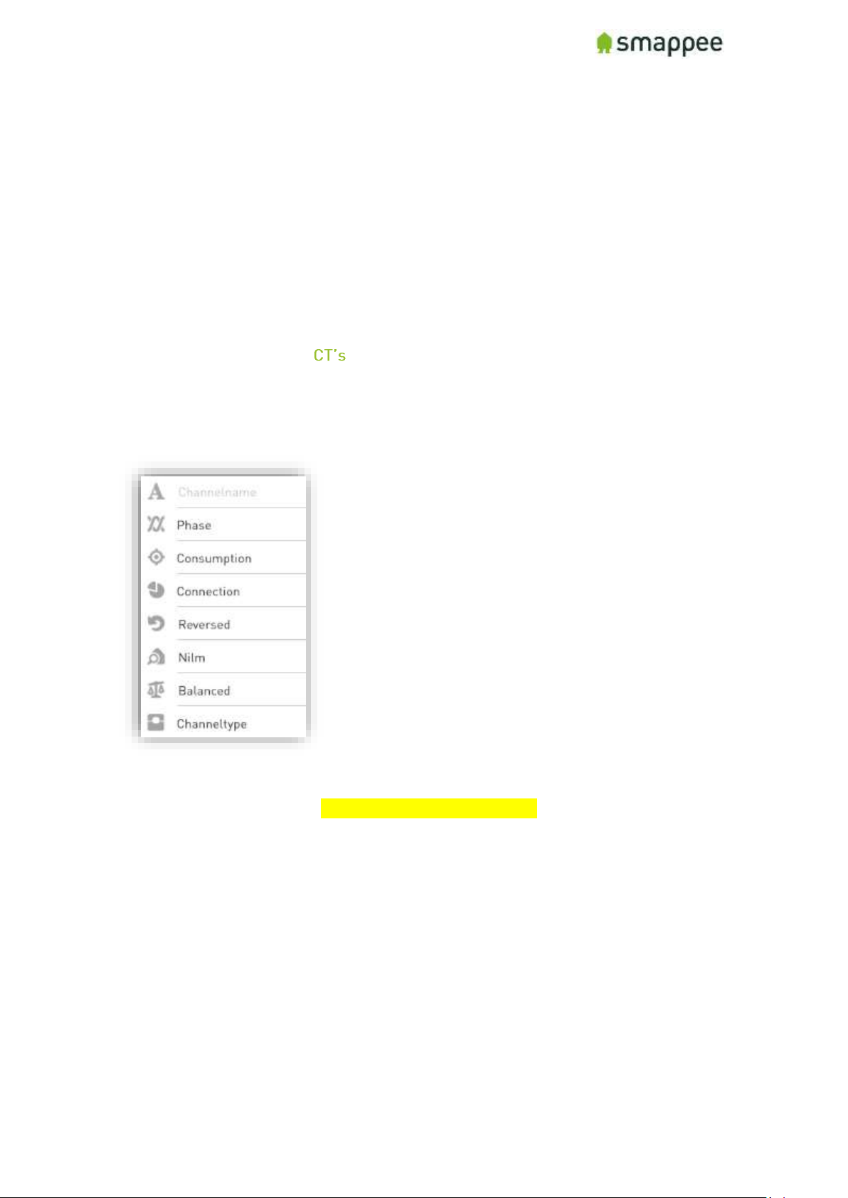
Smappee Pro Installation and Product Manual Page 64 of 74
Version 2.0.0, 24-09-2018, rev 102
Configure the Current Transformers
Overview
The current transformers of your Smappee need to be carefully configured in order to
get correct measurements.
The following sections explain:
• what configuration settings you need to configure
• where you can modify the configuration
Configuration Settings for
Each current transformer has a number of settings that need to be configured. These
include the name of channel, the electrical phase, and other electrical parameters.
A correct configuration is essential for correct measurements.
For a detailed explanation of these settings, please see section "Error! Reference
source not found.", on page Error! Bookmark not defined..
Where to Modify the Configuration
There are three locations where the configuration can be changed
1. in the App, during the first installation
2. in the App, any time after the installation
3. in the Expert Portal website
For simple and straightforward installations, you may use the method 1.
For more complex installation, you may need the method 2 or 3. Please see section
"Error! Reference source not found.", on page Error! Bookmark not defined., for
more information about how to use these methods.
Page 65
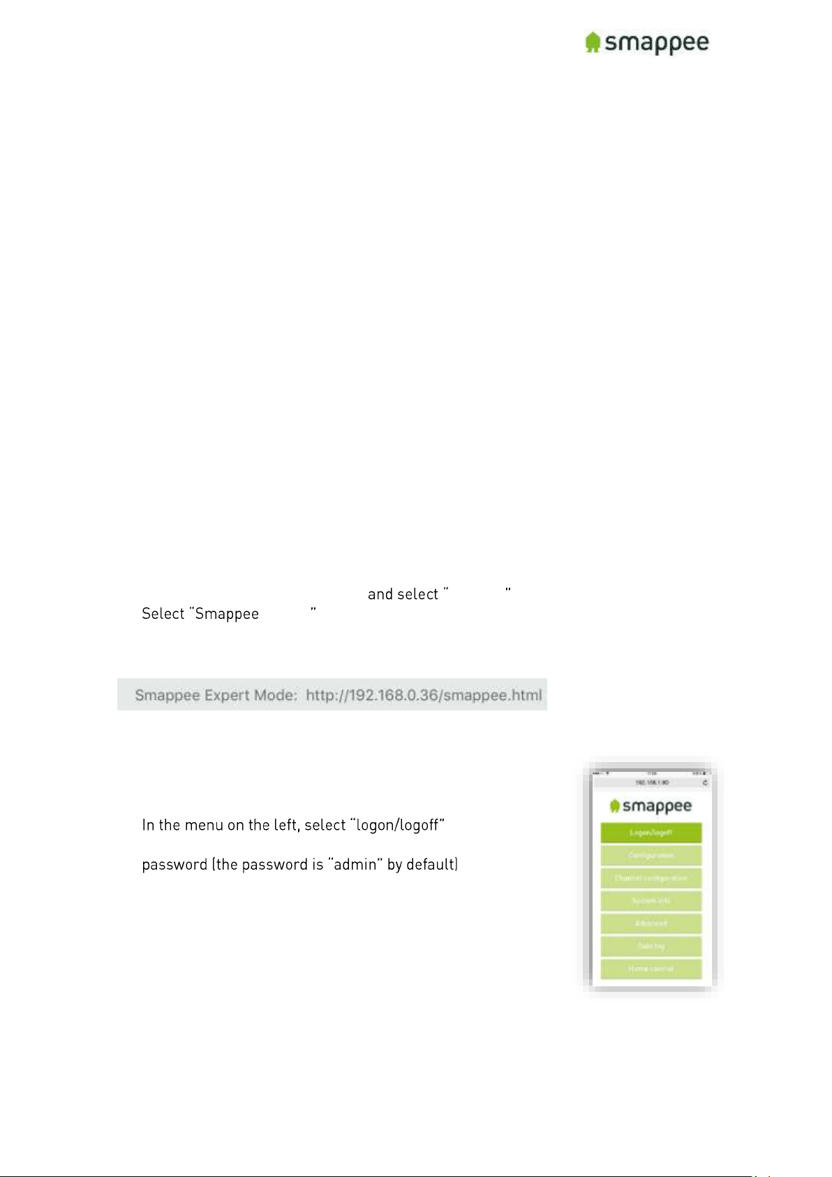
Smappee Pro Installation and Product Manual Page 65 of 74
Version 2.0.0, 24-09-2018, rev 102
Configure the Smappee in the Expert Portal
Overview
In the Expert Portal, you can diagnose and configure the electrical parameters of the
individual Current Transformers.
Expert Portal for Advanced Users
The expert portal is intended to be used by advanced users. We recommend not to
change any setting in the expert mode unless you know what you are doing.
Before you can Start
Your smartphone or tablet must be connected to the same local network ("subnet") as
the Smappee Pro.
Before you can connect, at least one Current Transformer needs to be connected to the
Smappee Pro.
Connecting to the Expert Portal
The Expert Portal is a web page that is accessible in the local network at the local IP
address of the Smappee.
Example:
http://192.168.0.1/smappee.html
You can open the Export Portal through your App. Please follow the instructions below:
• Go to the main menu of your App Settings
• Energy
• Select the serial number of your monitor
• Note the link (incl. the local IP address)
• Open the link in a web browser. You will see the login page of the Expert Portal.
Login to the Expert Portal
You can now log-in to the expert portal with the admin password.
•
• In the logon field on the right, please log-in with the
Page 66
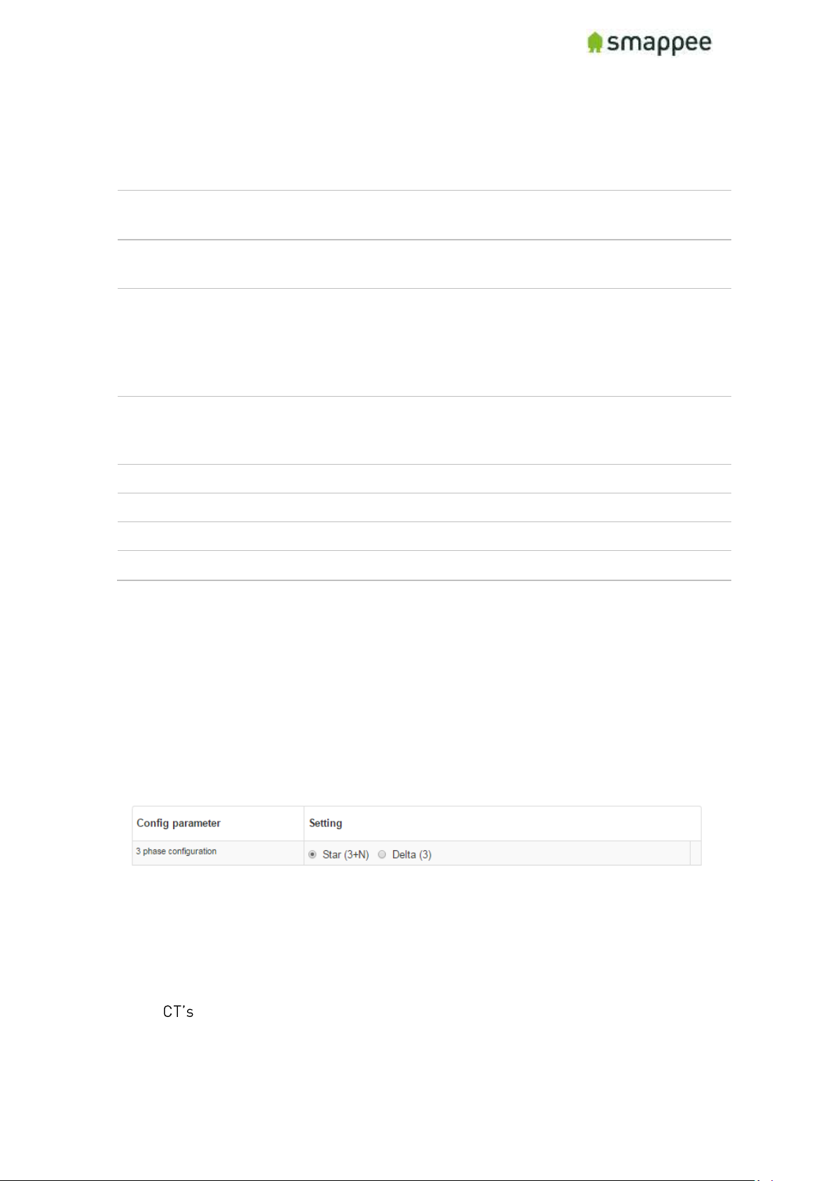
Smappee Pro Installation and Product Manual Page 66 of 74
Version 2.0.0, 24-09-2018, rev 102
Understanding the Menu Items
Please find below a brief explanation of the menus on the left side of the Expert portal.
For more information please refer to the page mentioned on the right.
Menu Item
Description
More
Details
Configuration
View and change the main electrical
parameters and settings.
page 67
Channel Configuration
Detailed configuration of the nine inputs of the
Current Transformers.
page
Error!
Bookmark
not
defined.
System Info
View various settings of the monitor such as
Wi-fi connection, the signal strength, serial
number, etc.
-
Advanced
Advanced settings and operations.
-
Networking
Network connection settings.
-
Data Log
Log of instantaneous values.
-
Home Control
Not used in the Smappee Pro.
-
Configuration menu
In the Configuration menu, select the type of electrical network.
In most cases, "Star" is the correct selection:
• three phase networks with neutral ("Star")
• US Split Phase (180°, 110 V)
Only in the rare case of three-phase networks WITHOUT neutral, you need to select
"Delta".
Channel Configuration menu
The menu item "Channel configuration" allows you to configure the Current
Transformers.
For details, please refer to the previous section "Error! Reference source not
found. " on page Error! Bookmark not defined..
Page 67
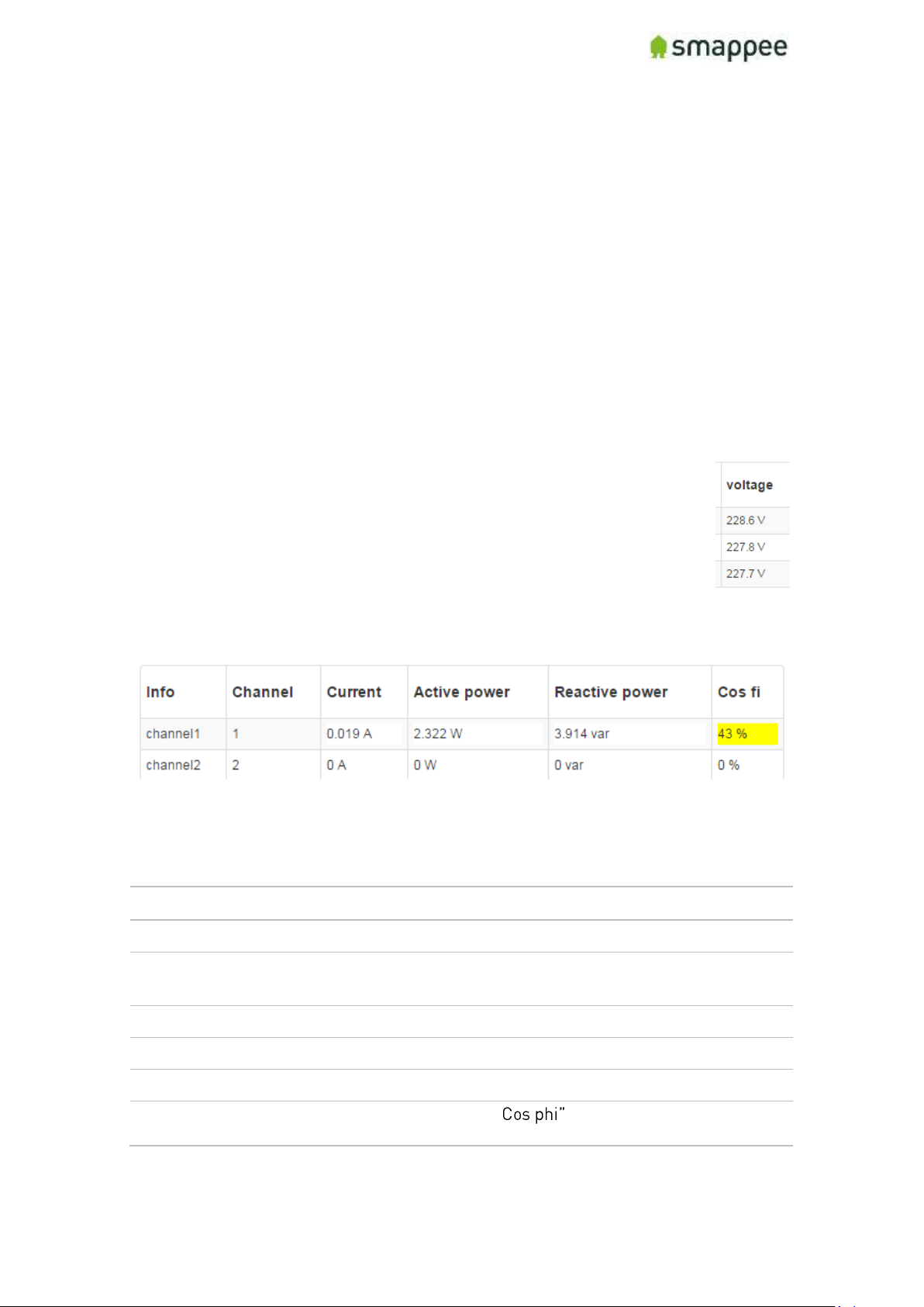
Smappee Pro Installation and Product Manual Page 67 of 74
Version 2.0.0, 24-09-2018, rev 102
Diagnose the Smappee in the Expert Portal
Overview
In case of complex installation or incorrect measurements, the Expert Portal provides
real-time information about specific electrical parameters of the measurements. This
information can be used to verify the installation and diagnose problems.
All information can be found in the Configuration menu. It shows three blocks of
information:
• Voltage display per phase
• Real-Time Measurements
• Connected Current Transformers
Voltage Display per Phase
This block displays the voltage that is measured at each phase input. For
details, see section "Connecting the Voltage Measurement Wires" on page
52.
Important: The voltage values should be approximately the same for each
phase.
Real-Time Measurements
This block displays the real-time measurements and electrical parameters for each
input.
The next paragraph explains these parameters in more detail.
Details for Parameters
The following table explains the parameters of the Real-Time Data.
Parameter
Explanation
Info
Input on the Smappee.
Channel
Measured channel. In Smappee Pro, this is identical to the
Info column.
Current
Current measured on that CT (Ampere).
Active power
Active Power (Watt).
Reactive power
Reactive Power (var).
Cos phi
Power Factor. Note: A " of less than 60% is visually
emphasized by yellow highlighting.
Page 68
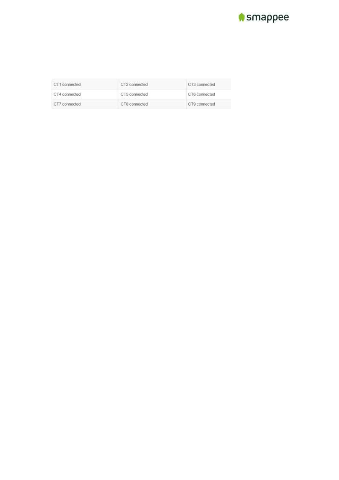
Smappee Pro Installation and Product Manual Page 68 of 74
Version 2.0.0, 24-09-2018, rev 102
Connected Current Transformers
This block shows on which inputs there is a Current Transformers connected. It helps
to detect bad connections.
Page 69
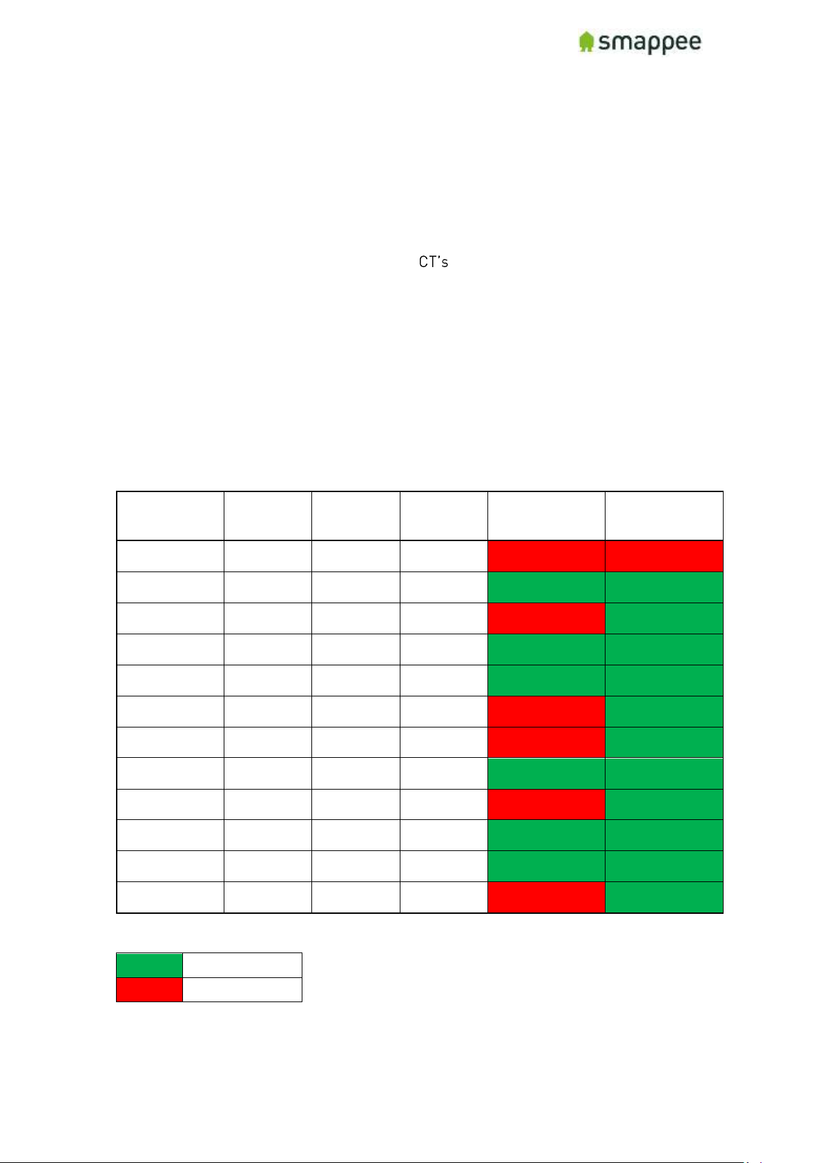
Smappee Pro Installation and Product Manual Page 69 of 74
Version 2.0.0, 24-09-2018, rev 102
Special Cases - Rogowski Coils
Overview
The Rogowski coils can only be used with the Smappee Pro. In addition, their use
depends on technical details of your installation. Contact Smappee Sales if you
consider using Rogowski Coils.
They are connected the same way as normal . Attach the Rogowski coil around the
cable and plug it into the Smappee Pro monitor.
If possible, Rogowski coils and other types of current transformers should not be
combined on the same unit of a Smappee Pro.
If you still wish to combine various types, please be aware of limitations regarding the
configuration options.
Allowed combinations
The use of Rogowski coils limits the number of allowed configuration options in the
Smappee. If an invalid setup is used, the measurements will be inaccurate.
Overview
Rogowski
Standard
CT
Standard
CT
Standard
CT
NILM ON
NILM OFF
Consumption
(Grid)
Production
(Grid)
No
No
Consumption
(Grid)
Production
(Off Grid)
Yes
Yes
Consumption
(Grid)
Production
(Off Grid)
Submeter
No
Yes
Consumption
(Grid)
Production
(Off Grid)
Production
(Off Grid)
Yes
Yes
Consumption
(Grid)
Production
(Off Grid)
Consumption
(Off Grid)
Yes
Yes
Consumption
(Grid)
Production
(Off Grid)
Consumption
(Off Grid)
Submeter
No
Yes
Consumption
(Grid)
Submeter
No
Yes
Consumption
(Grid)
Consumption
(Off Grid)
Yes
Yes
Consumption
(Grid)
Consumption
(Off Grid)
Submeter
No
Yes
Consumption
(Grid)
Consumption
(Off Grid)
Production
(Off Grid)
Yes
Yes
Consumption
(Grid)
Consumption
(Off Grid)
Consumption
(Off Grid)
Yes
Yes
Consumption
(Grid)
Consumption
(Off Grid)
Consumption
(Off Grid)
Submeter
No
Yes
Legend:
Yes
Valid setup
No
Invalid setup
For questions about other combinations, please consult the technical support of
Smappee at [email protected].
Page 70
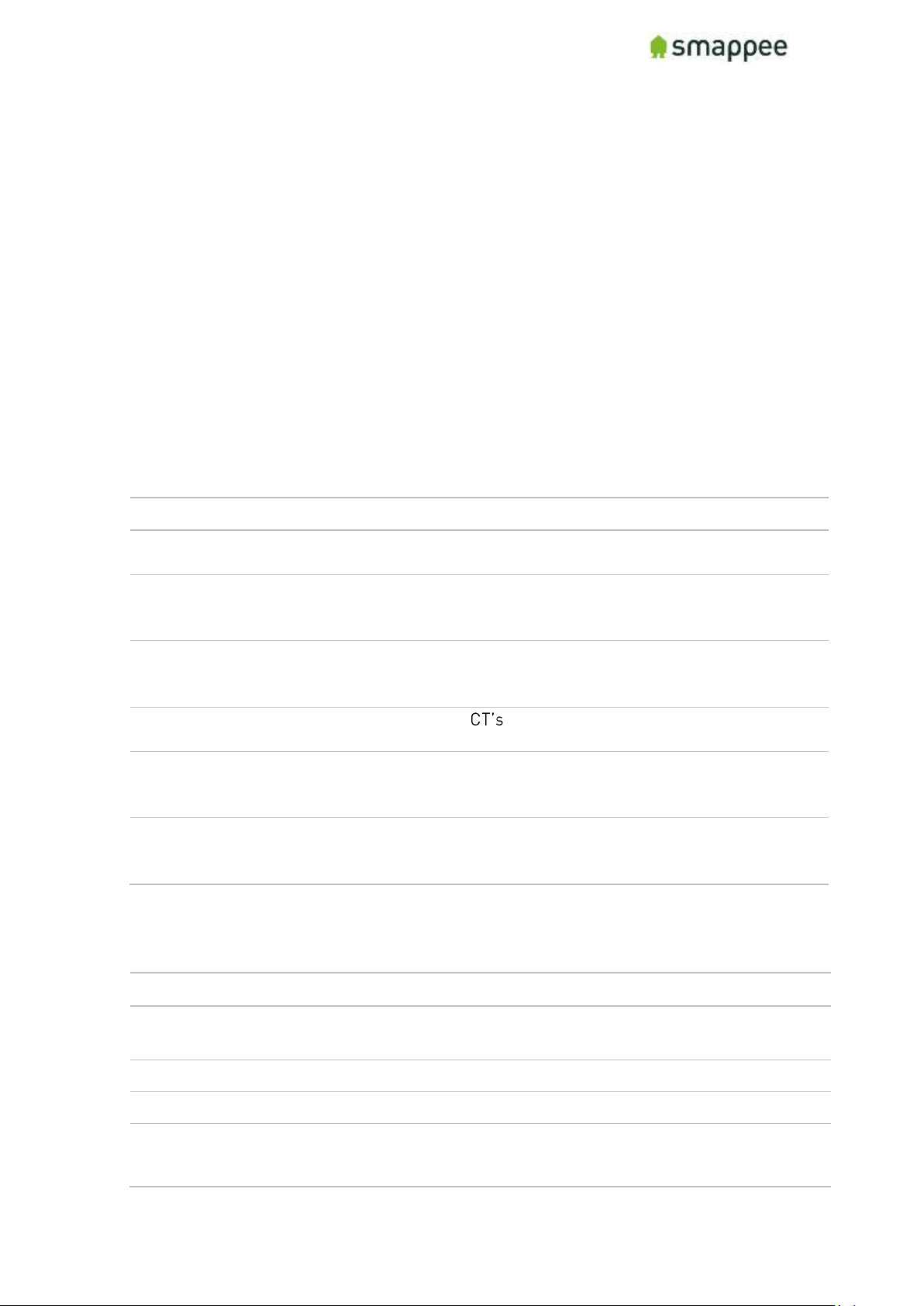
Smappee Pro Installation and Product Manual Page 70 of 74
Version 2.0.0, 24-09-2018, rev 102
Checklist for Correct Configuration
Overview
Once you reached this step, the installation is nearly complete. Before you finish work
you should carefully check the correctness of the configuration steps and of the actual
measurement values.
You need to verify that the measurements are correct. Do that before you finish
the installation.
Please perform three checks:
1. Quick Check
2. Checklist for Electrical Parameters
3. Checklist for Total Measurements
Quick Check
At this stage, the installation should meet the following criteria:
Check
Description
Details on
1.
The Smappee has been correctly powered on, according to the
instructions and checks.
page 59
2.
The Smappee is connected to the Internet and the Smappee
cloud. This is indicated by a BREATHING GREEN light.
page Error!
Bookmark
not defined.
3.
You see (some) real-time power values in the Bubbles of the App
or the Dashboard.
page Error!
Bookmark
not defined.
4.
You have configured the individual , either in the App or in
the Expert Portal.
page 64
5.
Your customer or central administration may require a particular
naming convention of the service location, you have assigned the
correct name to the service location.
page 60
6.
Your customer or central administration may require the sharing
of the created service location with a central user account. Make
sure you have done so.
page 60
Checklist for Electrical Parameters
In the menu item Configuration, please check the following parameters.
Check
Description
1.
The Star-Delta parameter in the "Configuration menu" panel should match the
electrical installation.
2.
The three voltage values should be approximately the same for each phase.
3.
The current measurement value of each CT should show plausible values.
4.
The Cos fi should be above 80%.
This check should be done during periods of high consumption.
Page 71
Smappee Pro Installation and Product Manual Page 71 of 74
Version 2.0.0, 24-09-2018, rev 102
Checklist for Total Measurements
Please view the real-time measurements in the Bubble-screen of the App or the
Dashboard. Run the following checks:
Check
Description
1.
The total consumption-bubble (grey) should display plausible values.
Compare the results with the main utility meter.
2.
The total production bubble (green) should display plausible values.
Compare the results with the solar inverter or batteries.
3.
When appliances are turned on or off, the consumption-bubble should
change accordingly.
4.
When appliances in the sub-meter circuits are turned on or off, the
consumption-bubble should change accordingly. (Make sure it does not
display the double power value).
5.
When appliances in the sub-meter circuits turn on or off, the correct name
should be displayed in the App.
6.
Perform the checks above for appliances on all three phases.
Troubleshooting
If the checks above show unexpected results, please verify the following installation
steps:
Chec
k
Description
See
1.
The wiring of the green 8-pin connector.
page 52
2.
The installation of the Current Transformers.
page 55
3.
The correct configuration in the "Configuration" menu.
page 67
4.
The correct configuration in the "Channel Configuration"
menu.
page Error!
Bookmark
not defined.
Once all checks are successfully completed, you may finish up the installation work.
Please see the next page for the final steps.
Page 72
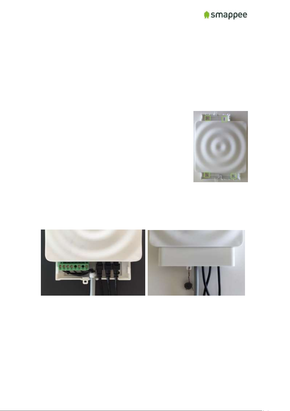
Smappee Pro Installation and Product Manual Page 72 of 74
Version 2.0.0, 24-09-2018, rev 102
Mounting and Enclosing
Overview
Now that the voltage measure terminal and the CT cables have been installed and
connected according to local electrical regulations, you can now finish up the physical
installation.
Important: The installer is responsible to ensure proper insulation of all wires.
Wires can be routed via the breakout area in the cover cap!
Mounting
If you have found a suitable location to mount the Smappee Pro
monitor to the wall, please remove the cover caps on each side
of the Smappee Pro monitor.
You will see the mounting holes provided on each side to
facilitate mounting your monitor to the wall.
Cover
Mount the cover cap on the Smappee Pro to cover all electrical connections.
If you used a voltage-rated multicore cable, you can also you an internal wire strap to
fix the cable under the covering cap.
Optionally you can use a strap or a lead seal to seal the cover cap in order to avoid any
contact with the wires.
Page 73

Smappee Pro Installation and Product Manual Page 73 of 74
Version 2.0.0, 24-09-2018, rev 102
Final Remarks
Gain insights
You have now successfully completed the installation. You can now gain more and
more insight in the energy consumption and production of the premises.
Support During Installation
In case of problems during performing an installation, please read this user manual
carefully. If this does not resolve the problem, you should contact the Smappee
Support team.
Non-Urgent support
Please send an email to [email protected].
Urgent Support
For Smappee Partners we offer a hotline specifically for installation support while the
partner is on the premises:
+32 56 38 02 56 (Europe) or +1 408 479 3748 (US).
This service is available during business hours (Central European Time), 6AM -11PM
(Eastern Time) and 6AM - 8AM (Pacific Time).
Training
Smappee offers various training courses for installers. These can be done by video
conference or in the Smappee offices.
Feedback
We always strive to improve our products and simplify the installation. We are happy to
hear your feedback.
[email protected]
Page 74
Smappee Pro Installation and Product Manual Page 74 of 74
Version 2.0.0, 24-09-2018, rev 102
Appendix
Sample Configuration Table (3-Phase Star Config)
Input
Description
Phase
Breaker
rating
CT Type
Connection type
1
Main Service
1
20A
50
Grid
2
Main Service
2
20A
50
Grid
3
Main Service
3
20A
50
Grid
4
Solar
2
15A
50
Solar/Production
5
HVAC
1
15A
50
Submeter
6
Home Battery
3
15A
50
Solar/Production
7
Lights Main Floor
2
15A
50
Submeter
8
Plugs Workshop
3
15A
50
Submeter
9
Pool Pump
3
20A
50
Submeter
Configuration Table Template
Input
Description
Phase
Breaker
rating
CT Type
Connection type
1 2 3 4 5 6 7 8 9
 Loading...