

Page 1
Smappee Plus Installation Manual Page 1 of 32
Version 1.6.2 B, 20-06-2017, rev 4
English
Version 1.6.2 B
Date: 20-Jun-2017
© 2013-2017 Smappee NV. All rights reserved.
Specifications are subject to change without notice.
All product names are trademarks of their respective companies.
Page 2

Smappee Plus Installation Manual Page 2 of 32
Version 1.6.2 B, 20-06-2017, rev 4
Welcome to Smappee
Page 3
Smappee Plus Installation Manual Page 3 of 32
Version 1.6.2 B, 20-06-2017, rev 4
Overview over the Installation Steps
Step-by-Step
The table below provides a global overview over all steps for installing the Smappee.
Please follow these steps carefully and in the provided sequence.
Step
Title
Page
Hardware and Physical Installation
1
Error! Not a valid bookmark self-reference.
3
2
Overview over the Installation Steps
3
3
The connectors and Inputs of the Smappee
5
4
Connecting the Power Supply
7
5
Connecting the Voltage Measurement Wires
8
6
Connecting the Current Transformers (CTs)
11
7
Current Transformer Variants
12
8
Preparing the Internet Connection
13
First Power-On
9
Initial Power-On of the Smappee Monitor
14
Connecting and Configuring
10
Login to the Smappee App
15
11
Connect to Internet and Cloud
16
12
Troubleshooting Internet and Cloud Access
18
13
Configure the Current Transformers
20
14
Where to Modify the CT configuration
21
15
Configuration Settings for
23
16
Configure the Smappee in the Expert Portal
25
17
Diagnose the Smappee in the Expert Portal
27
19
Checklist for Correct Configuration
29
Wrapping-Up
20
Mounting and Enclosing
31
21
Final Remarks
32
Page 4

Smappee Plus Installation Manual Page 4 of 32
Version 1.6.2 B, 20-06-2017, rev 4
Safety Instructions
Safety Warning
Working on your electrical installation can be dangerous. The Installation must be done
by a certified electrician.
Safety precautions
Please observe the following safety precautions in order to avoid potential electrical
shock, fire or personal injury:
Do not use this Product for any purpose other than for which it was intended.
Do not open the equipment or touch any of its electronic circuitry.
Do not attempt to repair or service any part of the Smappee Plus.
Only use the cables which were delivered with the Product.
Do not use the Product if damaged.
Do not use damaged current transformer or cables.
Do not immerse the Product in water, or any other liquids.
Do not expose the Product to heat, flame, steamy conditions or extreme cold.
Maintenance
Clean only the outside with a dry, clean cloth.
Do not use abrasive agents or solvents.
Specifications
Dimensions: 180x130x35mm (7x5.1x1.38 in)
Weight: 300g (10.6 oz)
Operating temperature: -10 - +50°C (14 - 122 °F)
Storage temperature: -20 - +70°C (-4 - 158 °F)
Relative humidity: 80% at 0 - +40°C (32 - 104 °F)
Operating altitude: 0 2.000 m (0 - 6561 ft)
EMC: EN 55022 (Class B)
Safety: conforms to UL/IEC/EN 61010-1 Ed3 2010, CAT II
Power supply: 90 264 VAC / 50..60 Hz
Inputs: Ph1,Ph2,Ph3,N
Voltage measurement inputs : Ph1,Ph2,Ph3,N
o Topology: 3 phase 3 or 4 wire, single phase, split phase
o Range: 50..270 Vrms Ph-N / 87..550 Vrms Ph-Ph
o Frequency: 45..65 Hz
Power consumption: Max. 5W
Product Identification
Product Article Number: monitor-e2
Page 5
Smappee Plus Installation Manual Page 5 of 32
Version 1.6.2 B, 20-06-2017, rev 4
The connectors and Inputs of the Smappee
Overview
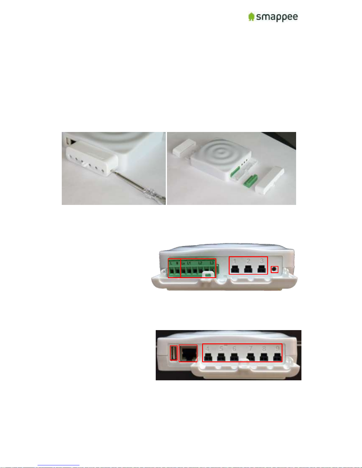
This section explains the connectors of the Smappee Plus.
Accessing the Connectors
To get full access to all connectors, you should remove the two covers.
For removing the covers, insert a screwdriver at the sides of the covers and carefully
pull up the cover.
Connectors at the Front
The picture shows the connectors at the front.
Power supply
Voltage terminal
CT connectors 1 to 3
Reset button
Connectors at the Back
The picture shows the connectors at the back.
USB port
Ethernet port (LAN)
CT connectors 4 to 9
Page 6
Smappee Plus Installation Manual Page 6 of 32
Version 1.6.2 B, 20-06-2017, rev 4
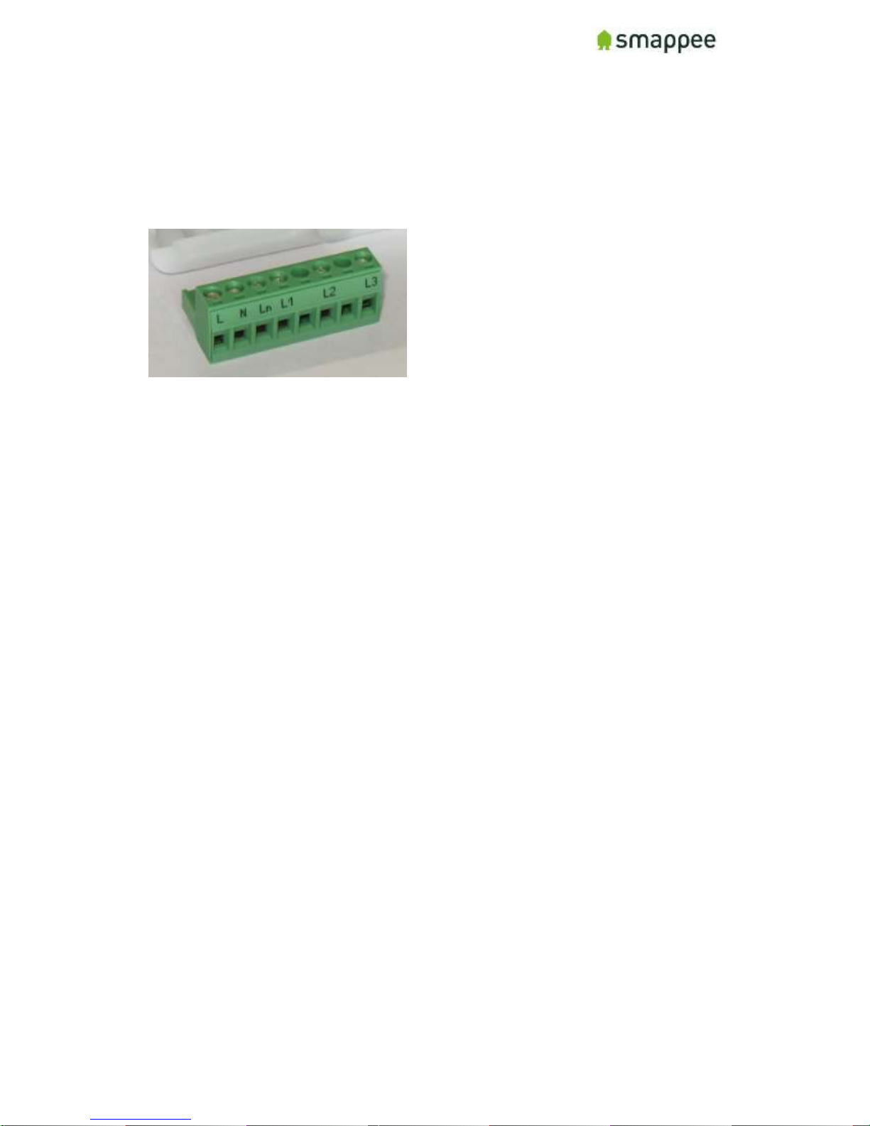
The Green 8-Pin Connector Block
The Smappee is delivered with a green 8-Pin connector block.
It is used to:
connect the Smappee power supply
measure the voltage of the power phases
You can find more details in the following sections.
Page 7
Smappee Plus Installation Manual Page 7 of 32
Version 1.6.2 B, 20-06-2017, rev 4
Connecting the Power Supply
Overview
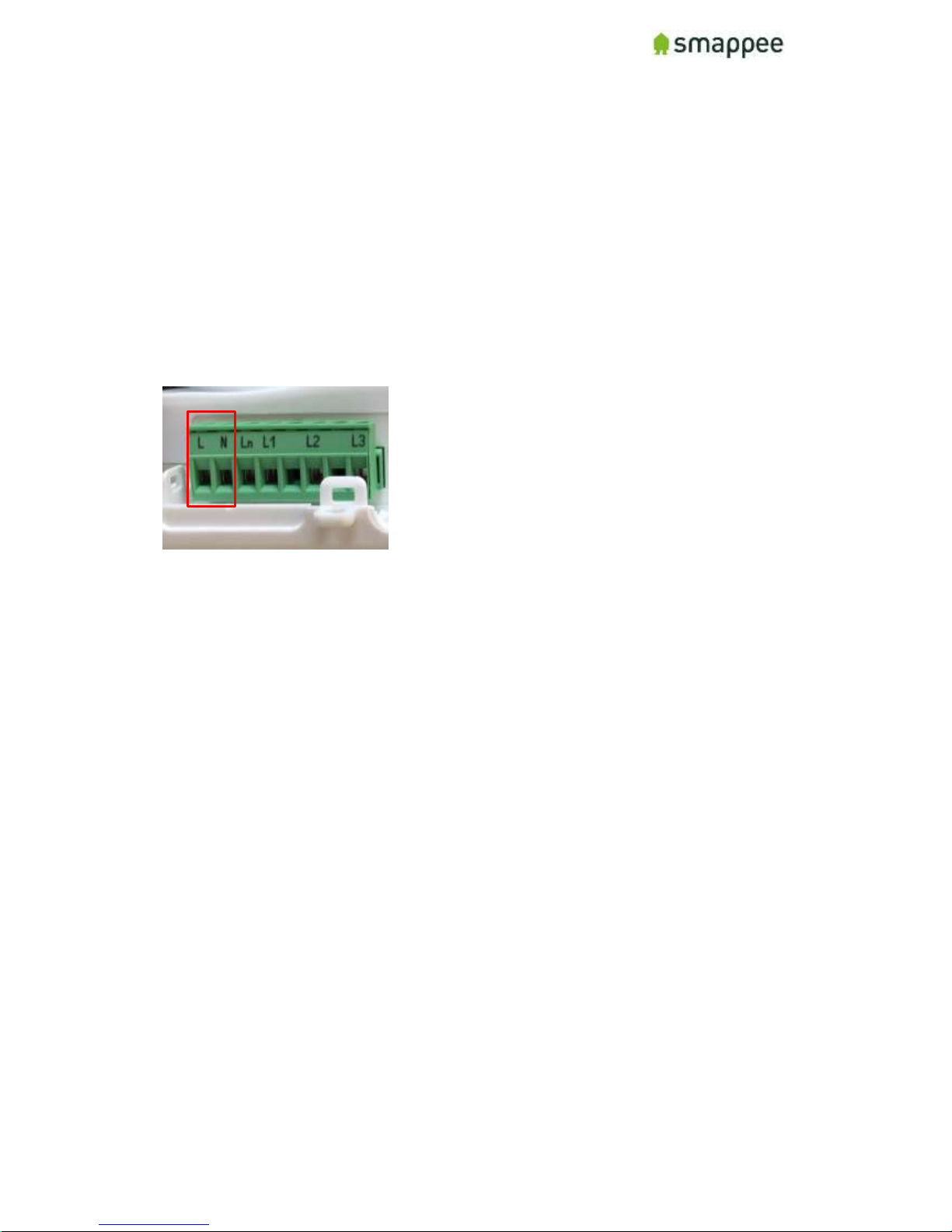
The Smappee is powered by the green 8-pin connector block.
Important: Always turn the main power off before performing the next steps!
Do NOT power-on the Smappee unless this manual specifically asks you to do so.
Connecting the wires
Instructions:
1. Connect the Phase wire of the power supply to the connector marked L.
2. Connect the Neutral of the power supply to the connector marked N.
Important Requirements
Important requirements for the installation:
The voltage of the power circuit should be in the range of 100-240 Vac.
A circuit breaker should always be used for the power supply. The circuit
breaker should be located close to the monitor and be easily reachable.
The circuit breaker should always be the disconnecting device for the Smappee
monitor.
All wires used should have a diameter between 0.75 and 2.5mm².
Note: None of the power connectors are used for any type of measurement.
Remember
Do NOT power-on the Smappee yet. This manual will specifically ask you to
power-on the Smappee in one of the installation steps later on.
Page 8
Smappee Plus Installation Manual Page 8 of 32
Version 1.6.2 B, 20-06-2017, rev 4
Connecting the Voltage Measurement Wires
Overview!
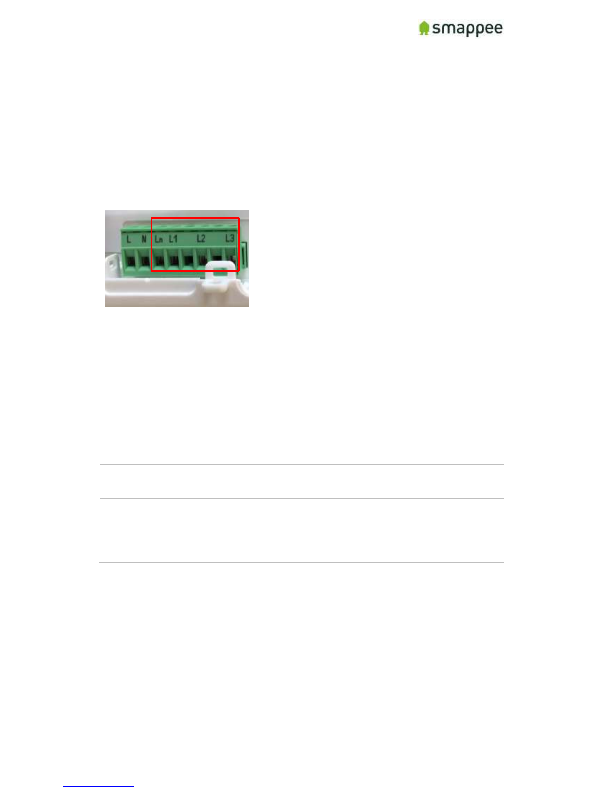
Smappee measures the various voltages and phases of the individual Phase wires and
the Neutral wire of the electrical installation. These wires need to be connected to the
inputs of the green 8-pin connector block.
This section explains how to connect the measured wires to the respective inputs of the
connector block.
Separated Power Supply
Please be aware that the measurement lines are fully separated from the lines of the
power supply. Consequently, the power lines may be connected to circuits on an UPS
or any other source without impacting the measurements.
However, this also results in the need to connect all lines to the measurement inputs.
This is particularly true for the input Ln, which always needs to be connected to the
Neutral line.
Inputs for Phase and Neutral
There are four inputs:
Input
Description
L1 - L3
Measurement inputs for the voltage and phase of each phase wire.
Ln
Measurement input for the Neutral reference.
Note: To measure the Neutral reference correctly, always connect
the Input Ln explicitly to the Neutral wire. There is NO internal link
with the Neutral line of the main power supply.
Installation Variants
The wiring of the voltage measurement inputs on the green 8-pin connector block
depends on the type of electrical installation.
There are four different Installation Variants:
Three-phase with Neutral ("Star")
Single phase
US Split phase (180°)
Three-phase without Neutral ("Delta")
On the next page, you find detailed instructions for the wiring.
Page 9

Smappee Plus Installation Manual Page 9 of 32
Version 1.6.2 B, 20-06-2017, rev 4
Installation Variants
The table below shows the wiring for the various installation variants.
Installation Variant
Wiring Schema
Three-Phase with Neutral ("Star")
1. Identify the three phase cables L1, L2 and L3
as well as the Neutral cable.
2. Connect the Neutral to the Ln.
3. Connect the phase cables to the correct input
of the voltage measure terminal:
Phase cable L1 to input L1
Phase cable L2 to input L2
Phase cable L3 to input L3
Single Phase
1. Identify the phase cable L1 and the Neutral
cable.
2. Connect the Neutral cable to the Ln, L2 and
L3 input.
3. Connect the phase cable L1 to the L1 input.
US Split phase (180°)
1. Identify the two phase wires L1 and L2 and the
Neutral wire.
2. Connect the Neutral wire to the Ln and L3
connector of the voltage measure terminal.
3. Connect the phase cables to the corresponding
inputs:
Phase cable L1 to the connector L1
Phase cable L2 to the connector L2
Three-Phase Without Neutral ("Delta")
1. Identify the three phase cables L1, L2 and L3.
2. Connect the first phase cable L1 to the
Neutral input Ln.
3. Then connect the phase cables to the
corresponding connectors of the voltage
measure terminal:
Phase cable L1 to the input L1
Phase cable L2 to the input L2
Phase cable L3 to the input L3
Page 10

Smappee Plus Installation Manual Page 10 of 32
Version 1.6.2 B, 20-06-2017, rev 4
Verify the Correctness of Installation
After finalizing the full Smappee installation, and while testing the Smappee
measurements, you should specifically verify the correct wiring of the 8-pin connector
block.
These checks will be explained at a later step during the installation, at section
"Checklist for Correct Configuration", on page 29.
Page 11
Smappee Plus Installation Manual Page 11 of 32
Version 1.6.2 B, 20-06-2017, rev 4
Connecting the Current Transformers (CTs)
Overview
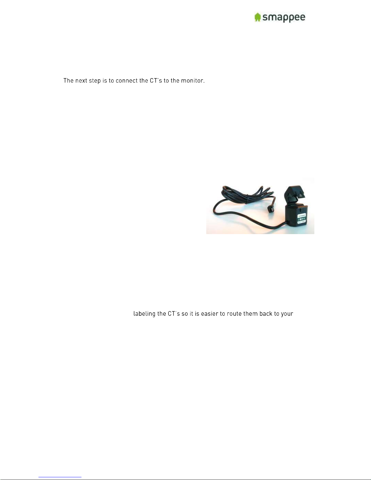
Each current transformer (CT) consists of a sensor and a plug. The sensor needs to be
attached on the cable and the plug needs to be inserted in one of the Inputs 1-9 of the
Smappee monitor.
Please note that each CT has an arrow inside. The correct direction of the arrow is very
important when installing the CT.
Configuration
The newly installed CTs always require an update of the configuration pages of the
Smappee.
For details, please see section "Configure the Current Transformers" on page 20.
Technical details
The Smappee Plus has inputs for 9 current
transformers.
The transformers are available in different sizes.
For all the different sizes, please see section
"Current Transformer Variants" on page 12.
Instructions
First, start by attaching the Current Transformers (CT) around the cables you wish to
measure. (These can be main incoming cables, sub-feeds, feeds from solar, etc.), just
put the CT around the cable and then close it.
Important: Pay attention to the direction of the arrow on the CT. The arrow always
points towards the electrical load, i.e. in the direction of the energy flow.
We strongly recommend
monitor afterwards (for example oven phase 1). Once the current transformers have
been installed around the cables, now route them back to the Smappee Plus.
Page 12
Smappee Plus Installation Manual Page 12 of 32
Version 1.6.2 B, 20-06-2017, rev 4
Current Transformer Variants
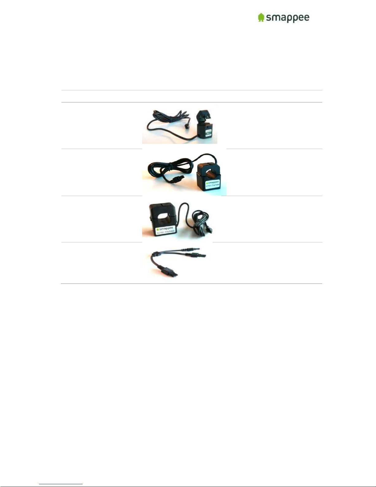
The table shows the current transformers that can be used with the Smappee Plus.
Smappee supports only the CTs listed below. No other CTs should be used!
Name/type
Picture
Specs
Current Transformer
SCT01-T10/50A
MC: 50A
MAX OV : 333 mV
MAX cable Ø: 10 mm
(0.39 in)
Current Transformer
SCT01-T16/100A
MC: 100A
MAX OV : 666 mV
MAX cable Ø: 16mm,
(0.63 in)
Current Transformer
SCT01-T24/200A
MC: 200A
MAX OV : 1332 mV
MAX cable Ø: 24mm,
(0.94 in)
Y-cable
AC-YC
Y-cable for combining
two current
transformers.
The length of a CT cable is 1.5 m (4.9 ft).
Legend:
MC: maximum current
MAX OV: Maximum output voltage
MAX cable Ø: Maximum phase cable diameter
Page 13
Smappee Plus Installation Manual Page 13 of 32
Version 1.6.2 B, 20-06-2017, rev 4
Preparing the Internet Connection
Overview
Now you should choose the method to connect the Smappee to the internet. There are
three alternative connection methods available:
Ethernet cable (recommended)
external Wi-Fi USB module
external 3G/4G internet USB dongle
This section will prepare the Smappee for connecting to the Internet at a later point
during the installation steps.
NO Hot-Plugging
All network cables and dongles need to be inserted or removed while the power is
OFF.
Ethernet cable (recommended)
The Smappee Plus monitor should be connected to the network by an RJ-45 Ethernet
cable.
The Ethernet cable should be connected to the Ethernet port of your monitor. When
using Ethernet, you should not connect a USB Wi-Fi or 4G dongle.
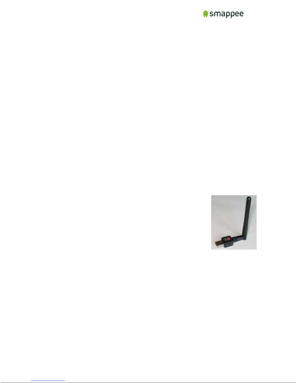
External Wi-Fi module (USB)
The external Wi-Fi module connects the Smappee Plus to a local Wi-Fi
network. It should be plugged in the USB port of the Smappee.
If you experience problems with the Wi-Fi connectivity, please consult
the Wi-Fi checklist. You can find the checklist at
http://support.smappee.com. Search for "checklist".
Important: You can only use the module that is supplied by
Smappee. Other devices are not supported.
External 3G/4G Dongle (USB)
The external 3G/4G dongle directly connects your
Smappee monitor to the internet through an 3G/4G
connection.
Smappee ships the dongle preconfigured with a
SIM card, as part of your data subscription option.
Please note this device requires a stable 3G/4G network signal. Please check this
before buying this device.
Connect the cable or USB module
Once you have selected the connection method, please insert the selected cable or
module in the respective Smappee port, while the Smappee is still turned off.
Page 14
Smappee Plus Installation Manual Page 14 of 32
Version 1.6.2 B, 20-06-2017, rev 4
Initial Power-On of the Smappee Monitor
Introduction
Your Smappee Plus monitor is now nearly ready for the first power-on. Please
complete a number of checks, before you power-on the Smappee.
Important: The Smappee Plus is not yet completely installed and insulated.
Perform the actions of section "Mounting and Enclosing", on page 31, before
leaving the installation place.
Check Before First Power-On
Please do a final check:
ID
Check
More info
1.
Smappee is connected by a circuit breaker.
page 7
2.
The 8-pin connector block is correctly wired for both the main
power supply as well as the measuring wires.
page 8
3.
The current transformers are connected at your electrical
installation and to the inputs at the Smappee.
page 11
4.
The hardware for the network (Ethernet cable or USB dongle)
is connected to the Smappee.
page 13
5.
You understand that the Smappee Plus is not yet completely
installed and properly insulated. Do not leave the place of
installation before completing the installation.
page 31
Power On
Now use the circuit breaker to turn on the power.
Lights for Network Status
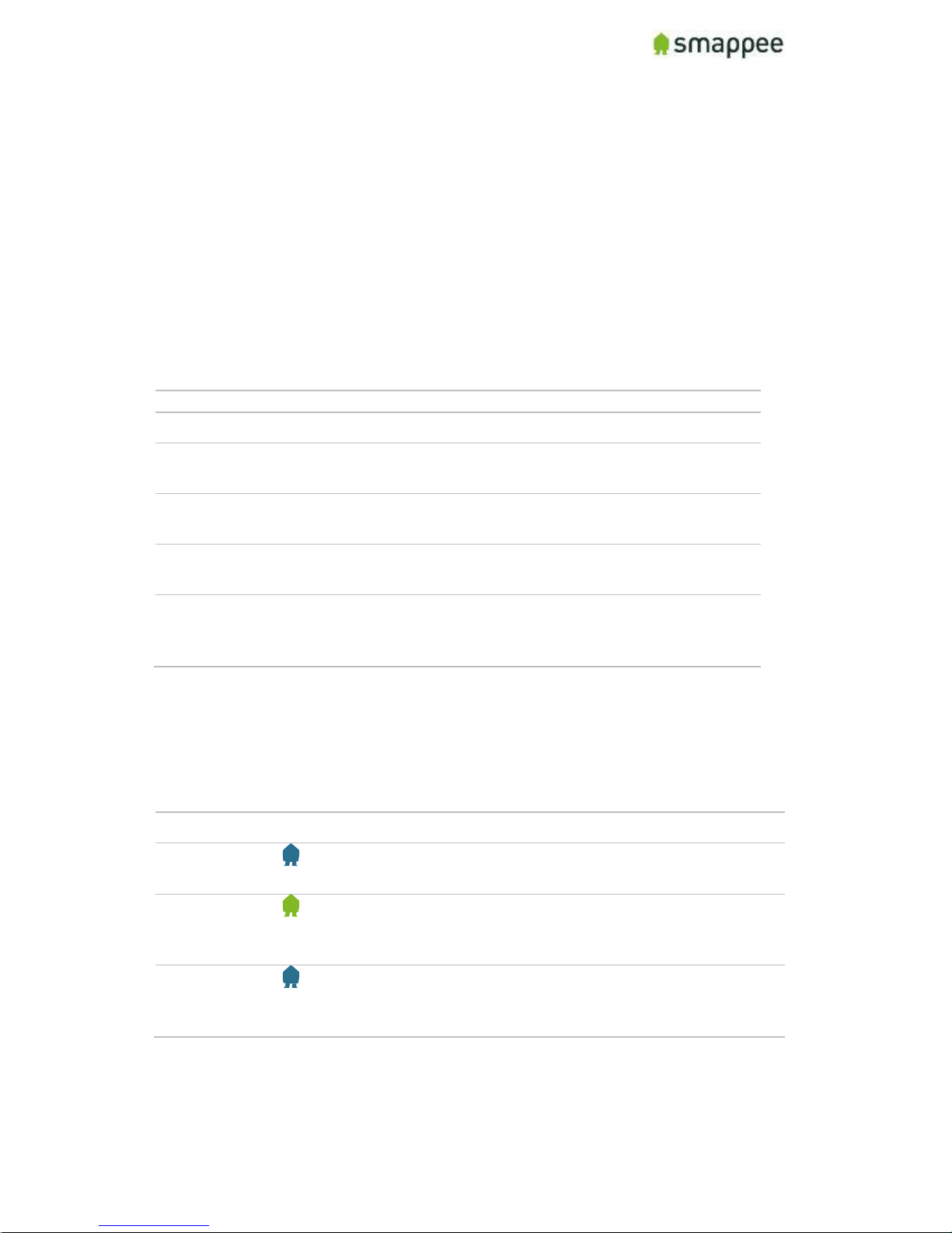
Smappee indicates the progress of the power-on and the network status by the light.
Light
Description
Blue Steady
The Smappee is powering on. Please wait for about 3 minutes.
Hint: The light may briefly go dark during that time.
Green Steady
The Smappee is connected to the local network and ready to be
installed by the App. The Smappee should show this color when
it is connected by Ethernet or a 3G/4G dongle.
Blue Flashing
The Smappee monitor is ready to be connected to the local
network and to be installed by the App. The Smappee should
show this color when it is connected by a Wi-Fi dongle.
If you see one of these colors, proceed to the next page of this manual.
If, however, Smappee shows a different color, please refer to section "Troubleshooting
Internet and Cloud Access" on page 18.
Page 15

Smappee Plus Installation Manual Page 15 of 32
Version 1.6.2 B, 20-06-2017, rev 4
Login to the Smappee App
Overview
The Smappee App is required to activate your monitor and link it to your user account in
the Smappee cloud.
Before you continue the installation, make sure you are logged in correctly:
with a correct user name
at a correct service location.
Installing the Smappee App
The App is available on Android and iOS. It can be downloaded from the Apple store or
the Android marketplace.
Note: The App is not available for Windows smartphones or Windows operating
systems.
Create User Account, then Login
Once installed, open the App and login to your user account, or create a new user
account.
Multiple User/Multiple Service Locations
If you install multiple Smappee Plus monitors at multiple locations, make sure that you
are logged in with the correct user name. Also make sure, that you have activated the
correct service location.
Watch out! If you use the wrong user name or service location, you may invalidate
both installations.
Page 16
Smappee Plus Installation Manual Page 16 of 32
Version 1.6.2 B, 20-06-2017, rev 4
Connect to Internet and Cloud
Overview
Now, you connect your Smappee Plus to your account on the App/Smappee cloud. If
you use Wi-Fi as the network connection method, you also provide the Wi-Fi network
name (SSID) and Wi-Fi password.
The installation process is largely guided by the Smappee App. You should follow the
instructions on the screen.
Check Before You Start
Please do a final check:
ID
Check
More info
1.
Your Smappee Plus is powered on. (It will take about 3
minutes.)
page 14
2.
Your Smappee Plus is showing a Green Steady (Ethernet,
3G/4G dongle) or Blue Flashing (Wi-Fi) light.
page 14
3.
Your App is installed on your smartphone.
page 15
4.
In the App, you are logged in with the correct user name and,
if applicable, at the correct service location.
page 15
Starting the Installation in the App
To start the installation of the Smappee Plus,
follow these steps:
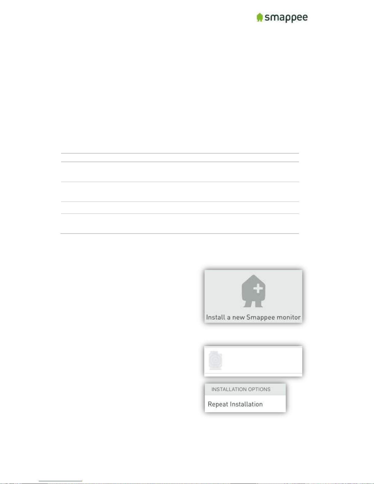
If you see a screen with an Install-Bubble:
1. Click on the icon "Install a new
Smappee monitor".
If the app does not show this icon, please
perform the following steps, depending on
the available screen options:
1. Select the menu item "Settings"
2. and/or select " Smappee Plus"
3. and/or "Repeat installation"
Smappee Plus
Page 17

Smappee Plus Installation Manual Page 17 of 32
Version 1.6.2 B, 20-06-2017, rev 4
Follow the Instructions on the Screen
After starting the installation (see previous paragraph),
continue with these steps:
1. Follow the instructions, until you reach the
screen "We will now configure your Smappee by
asking you a few questions about your
installation".
2. Once you reach this step, please hold for a
moment and perform a check. Make sure that
the Smappee shows a Green Breathing light.
Check: Green Breathing Light
If this check is OK, please continue at section "Configure the Current Transformers" on
page 20.
If this check is NOT OK, consult the section "Troubleshooting Internet and Cloud
Access" on the next page.
Page 18
Smappee Plus Installation Manual Page 18 of 32
Version 1.6.2 B, 20-06-2017, rev 4
Troubleshooting Internet and Cloud Access
Introduction
This section provides help in case of problems during the connection step.
Note: The connection to the Internet and the Cloud needs to be fully functional before
you can continue the installation (i.e. configuring the Smappee for accurate
measurement).
Understanding the milestones
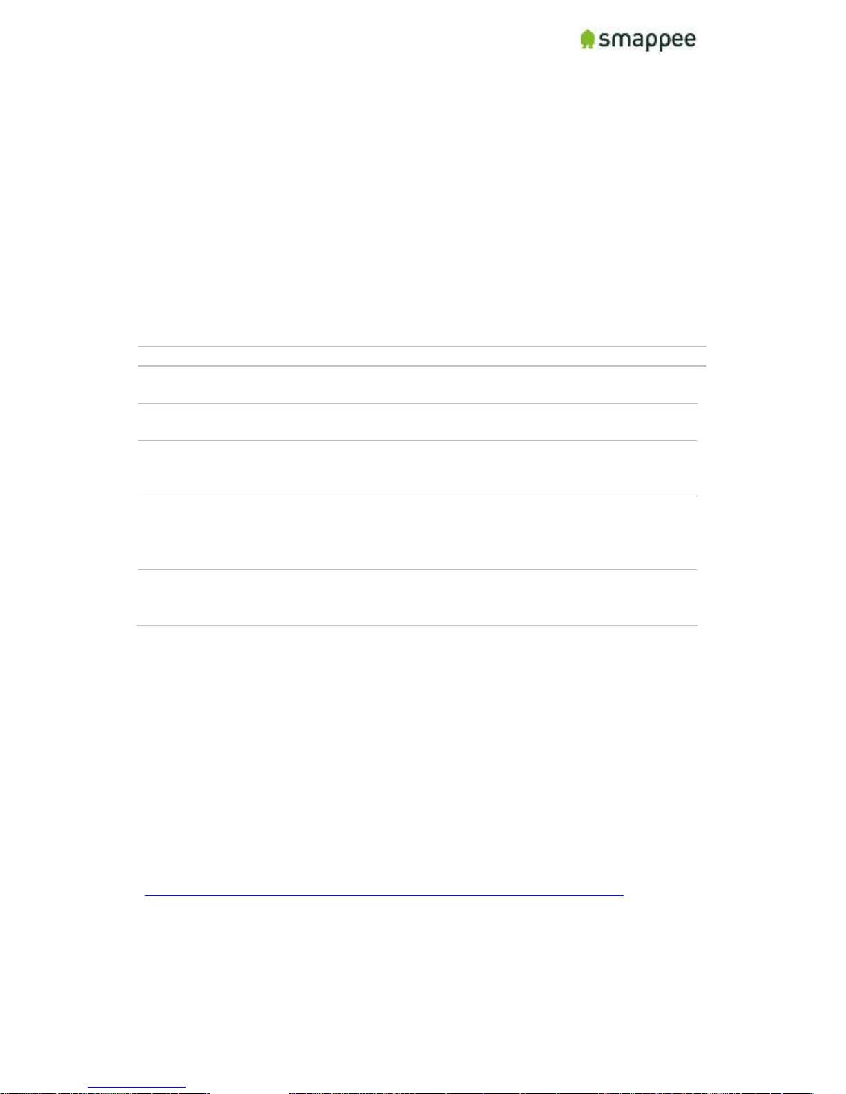
The connection to the Internet and Cloud has the following main milestones. Please
refer to them in case of problems.
Step
Milestone
Success Indicator
1.
Connect to Wi-Fi network (if applicable) and/or local
network.
Green steady light
2.
Smappee contacts the Smappee cloud.
-
3.
The App and the Smappee monitor "meet" in the cloud
and connect to each other.
App shows screen
with "jumping"
Smappee logo
4.
The Smappee monitor starts measuring the power
signals (even if the configuration is not yet correct). It is
important that at least one current transformer is
connected.
-
5.
The App receives real-time measurements from the
monitor and displays them in the main screen.
Note: The actual values are not yet necessarily correct.
Some values in the
App main screen,
like "1 W"
Issues with Local Network (Ethernet or Wi-Fi)
If your Smappee Plus is connected by Ethernet or Wi-Fi make sure that the site system
administrator is aware of the installation. They may need to change settings in the
network and firewalls.
Hint: Experience shows that you should contact the IT responsible of the installation
site long before the installation date.
Wi-Fi Checklist
If you experience problems with the Wi-Fi connectivity, please consult the Wi-Fi
checklist. You can find the checklist at http://support.smappee.com. Search for
"checklist".
https://support.smappee.com/hc/en-us/articles/201618739-Wi-Fi-checklist
Remember: The dongle needs to be inserted BEFORE you power-on the Smappee Plus.
Page 19
Smappee Plus Installation Manual Page 19 of 32
Version 1.6.2 B, 20-06-2017, rev 4
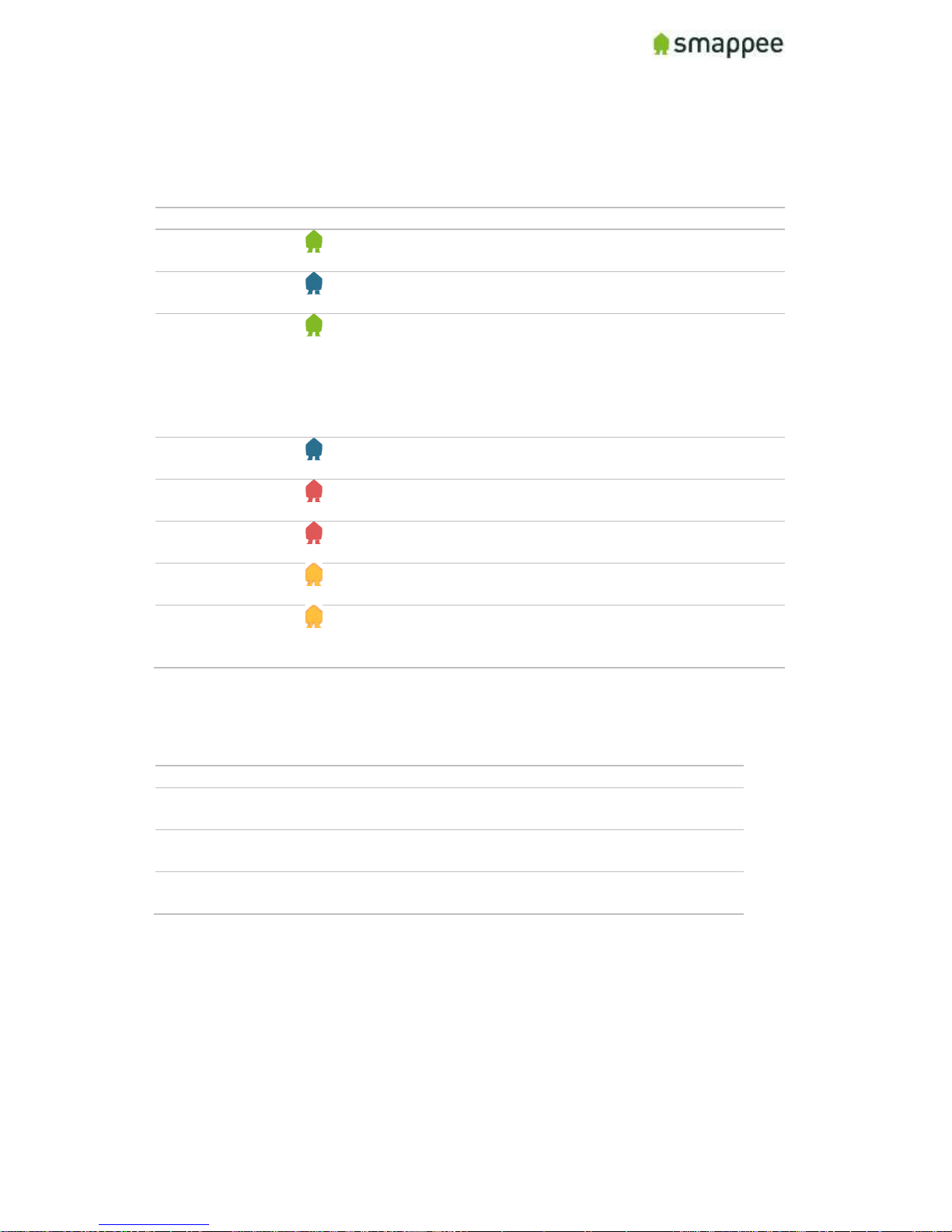
Colors of the Smappee Light
The table below provides an overview over all colors that may be shown during the
installation.
Color
Description
Green Breathing
All good. The monitor is working correctly. You can continue
the next steps for installation and configuration.
Blue Steady
The monitor is starting up. This may take up to 3 minutes.
The light may briefly go dark during that time.
Green Steady
Network connectivity successful, but Smappee not yet
connected to a user account.
Ethernet: Connected to the local network.
Wi-Fi: Connected to the Wi-Fi and the local network
(i.e. the Wi-Fi password is correct)
4G dongle: Connected to the 4G network.
Blue Flashing
The monitor is ready to be connected to the local Wi-Fi
network and to be installed on the App.
Red Steady
The monitor is missing connectivity with internet during
startup. Connection issue.
Red Flashing
The monitor had a previous working internet connection but
has now lost connectivity to the internet.
Orange Steady
The Wi-Fi hotspot access point has been activated, in order
to allow the Smappee to receive a new Wi-Fi password.
Orange Flashing
Smappee is trying to open an Wi-Fi hotspot access point.
Please wait a few seconds. The light will turn Orange Steady
in a few moments.
Colors of 4G dongle
If your Smappee Plus is connected by 4G dongle, please check the colors of the dongle.
Color
Description
Any steady
(Blue, Green, Cyan)
Successfully connected. The dongle is successfully
connected to the cellular network.
Any slow blinking
(Blue, Green, Cyan)
The dongle is registering with a cellular network.
Green fast blinking
(1 per second)
Stick is powered on. No connection.
Remember: The dongle needs to be inserted BEFORE you power-on the Smappee Plus.
Page 20
Smappee Plus Installation Manual Page 20 of 32
Version 1.6.2 B, 20-06-2017, rev 4
Configure the Current Transformers
Overview
The current transformers of your Smappee need to be carefully configured in order to
get correct measurements.
The following sections explain:
where you can modify the configuration
what configuration settings you should use.
Where to Modify the Configuration
There are three locations where the configuration can be changed
1. in the App, during the first installation
2. in the App, any time after the installation
3. in the Expert Portal website
For simple and straightforward installations, you may use the method 1.
For more complex installation, you may need the method 2 or 3. Please see section
"Where to Modify the CT configuration", on page 21, for more information about how to
use these methods.
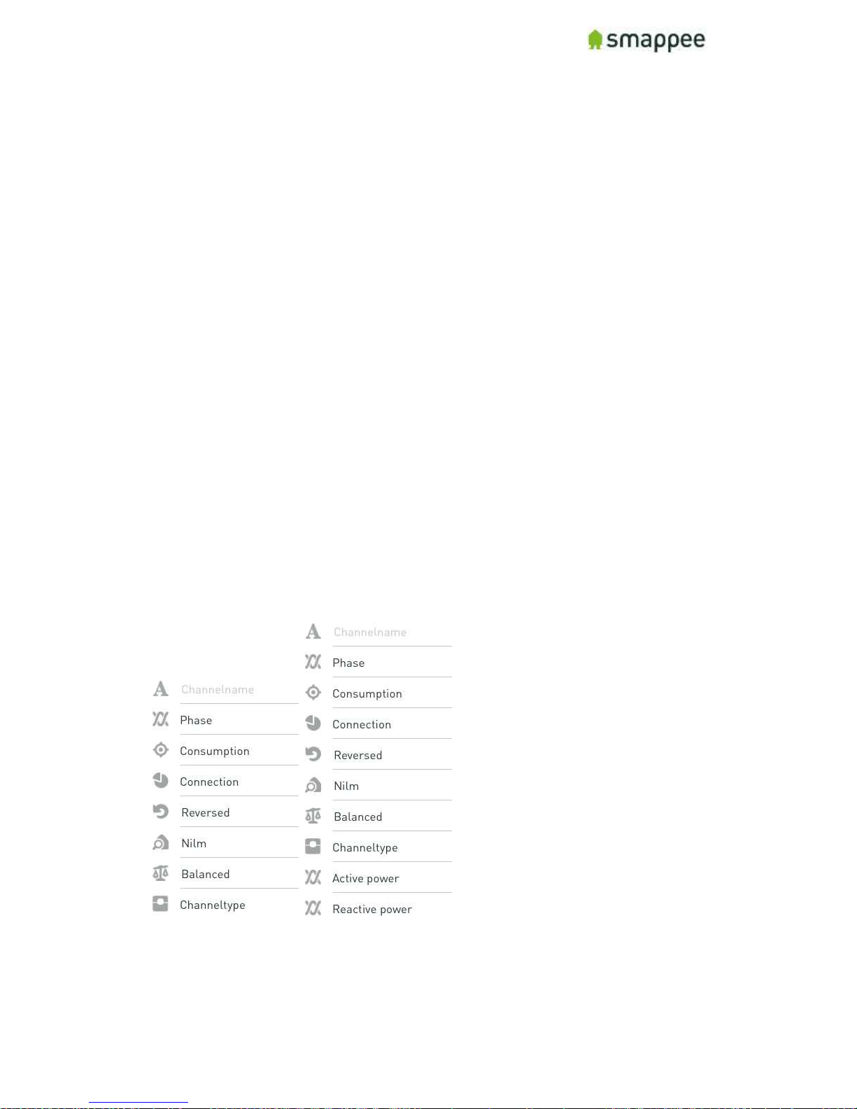
Configuration Settings for CTs
Each current transformer has a number of settings that need to be configured. These
include the name of channel, the electrical phase, and other electrical parameters.
For a detailed explanation of these settings, please see section "Configuration Settings
for ", on page 23.
Page 21
Smappee Plus Installation Manual Page 21 of 32
Version 1.6.2 B, 20-06-2017, rev 4
Where to Modify the CT configuration
Overview
As mentioned before, there are various methods for modifying the CT configuration:
1. in the App, during the installation steps
2. in the App, after the installation steps
3. in the Expert Portal website
This section explains the benefits of each method, as well as how to use it
Using the Configuration Methods
The table explains in which situations each of the configuration methods can be usefully
applied.
Method
When to use
Expertise
level
1
App, during
installation
As a first quick configuration during an
installation, for simple settings.
Medium
2
App, after
installation
To repeat or modify the configuration after
the initial installation.
Medium
3
In the Expert
Portal website
For advanced installations and error
diagnostics.
Expert
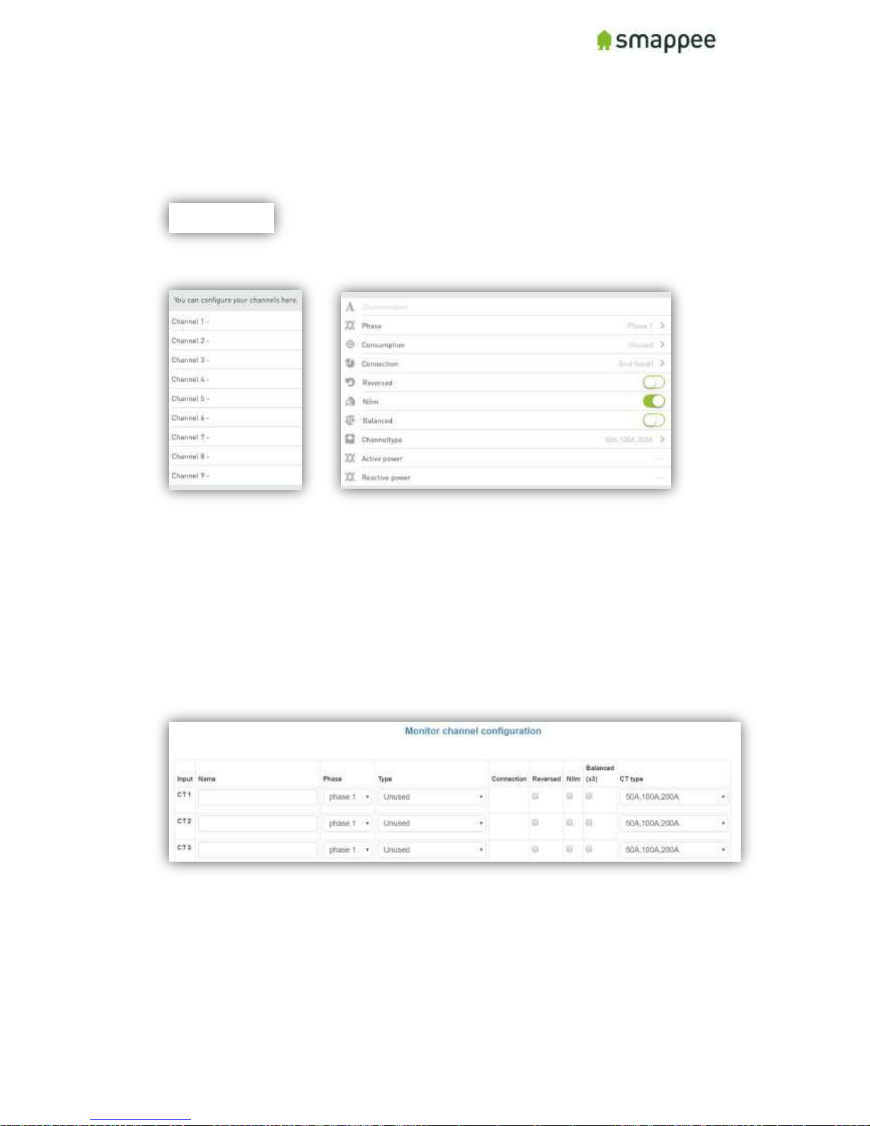
App, during installation
This method will be automatically started as part of each installation in the App. Once
you have successfully connected Smappee to your account, the App will automatically
start the configuration steps.
Page 22
Smappee Plus Installation Manual Page 22 of 32
Version 1.6.2 B, 20-06-2017, rev 4
App, after installation
Once you have completed the initial installation, you can still change the configuration
of the current transformers at any time.
Please use menu item "Settings", select Smappee Plus, then "Channel Configuration".
The app allows you to change the configuration.
Expert Portal
The Expert Portal is a website on the Smappee device that is intended for advanced
installers.
Within the expert portal, you find a menu item "Channel Configuration", where you can
configure the current transformers.
For more details, please see section "Configure the Smappee in the Expert Portal", on
page 25.
Page 23
Smappee Plus Installation Manual Page 23 of 32
Version 1.6.2 B, 20-06-2017, rev 4
Configuration Settings for CTs
Overview
Each current transformer has a number of configuration settings. Please configure the
current transformers carefully.
A correct configuration is essential for correct measurements.
Settings
The table shows the settings for the configuration of each CT.
Setting
Description
Input
Number of the Input connector on the Smappee.
Name
Provide a name for this specific input.
Note: You should carefully select an unmistakable name, since it is
used in many user-facing locations on the websites and the App.
Phase
Configure the phase that the CT of this specific input is measuring.
Type
In the type menu, you can choose between 3 options:
Consumption
Production
Unused
For more information regarding this choice please see page 24.
Connection
Here you can choose what connection type the CT is:
Grid - CT measures the total consumption of the installation
Off-Grid - CT measurements are added on top of the total
Submeter - CT measurements are sub-sets within the total
For more information regarding this choice please see page 24.
Reversed
Select this checkbox to invert the 'direction' of the current
transformer. This option is equivalent to physically re-install the CT
with the arrow pointing in the other direction.
Note: This option should only be used if it is physically impossible to
install the CT correctly.
NILM (Appliance
Detection)
Select this checkbox to activate the automatic appliance detection on
that particular input.
Balanced 3x
When selected, the CT measures (only) one phase of a three-phase
line, and extrapolates the total power over the three phases.
This setting is useful for submetering of three-phase load with a
single Current Transformer. It yields good results as long as the load
over the three phases is "balanced".
CT Type
Here you can configure the Current Rating of the current transformer
that is connected in that input. (50A-100A-200A-400A-800A).
Page 24
Smappee Plus Installation Manual Page 24 of 32
Version 1.6.2 B, 20-06-2017, rev 4
Type: Consumption, Production or Unused?
The type menu, you can choose between 3 options:
Option
Description
Consumption (Load)
This input measures an appliance (that is an consumer van
energy).
Production
(Solar/Wind)
This input measures an energy producer, such as a
photovoltaic installation.
Unused
You choose this option if the CT entry is not used.
Connection: Grid, Off-Grid or Sub-Meter?
The table shows the three connection types for the inputs.
Connection
type
Description
Grid
Measures Total Consumption on the Main Circuit Board
Indicates that this CT is connected directly to the main circuit board,
and thus measures the Grid Total.
Note: For each phase (L1, L2, L3) there can be only ONE input
configured as GRID.
-
Bubble in the App or the Dashboard.
Off-grid
Measures Extra Power on a separate Circuit Board
Indicates that the CT is connected to a separate circuit board that is
not connected to the main circuit board.
The value is ADDED to the total of GRID. Consequently, the
measurements will be added to the grey Consumption-Bubble.
Submeter
Measures a sub-circuit of the Grid
Indicates that the CT is connected to a sub-circuit, that is connected
to the Main Circuit Board.
The values of these CT's will NOT be added to the total GRID.
Display of Active and Reactive Power
During the configuration it is helpful to view the real-time values of the active and
reactive power. The app displays these values the configuration settings screen.
Page 25
Smappee Plus Installation Manual Page 25 of 32
Version 1.6.2 B, 20-06-2017, rev 4
Configure the Smappee in the Expert Portal
Overview
In the Expert Portal, you can diagnose and configure the electrical parameters of the
individual Current Transformers.
Expert Portal for Advanced Users
The expert portal is intended to be used by advanced users. We recommend not to
change any setting in the expert mode unless you know what you are doing.
Before you can Start
Your smartphone or tablet must be connected to the same local network ("subnet") as
the Smappee Plus.
Before you can connect, at least one Current Transformer needs to be connected to the
Smappee Plus.
Connecting to the Expert Portal
The Expert Portal is a web page that is accessible in the local network at the local IP
address of the Smappee.
Example:
http://192.168.0.1/smappee.html
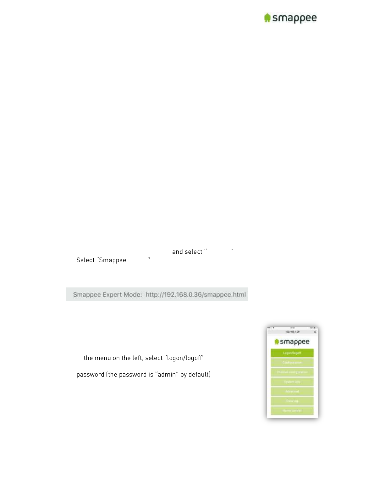
You can open the Export Portal through your App. Please follow the instructions below:
Go to the main menu of your App Settings
Energy
Select the serial number of your monitor
Note the link (incl. the local IP address)
Open the link in a web browser. You will see the login page of
the Expert Portal.
Login to the Expert Portal
You can now log-in to the expert portal with the admin password.
In
In the logon field on the right, please log-in with the
Page 26
Smappee Plus Installation Manual Page 26 of 32
Version 1.6.2 B, 20-06-2017, rev 4
Understanding the Menu Items
rt portal.
For more information please refer to the page mentioned on the right.
Menu Item
Description
More
Details
Configuration
View and change the main electrical
parameters and settings.
page 27
Channel Configuration
Detailed configuration of the nine inputs of the
Current Transformers.
page 23
System Info
View various settings of the monitor such as Wifi connection, the signal strength, serial
number, etc.
-
Advanced
Advanced settings and operations.
-
Networking
Network connection settings.
-
Data Log
Log of instantaneous values.
-
Home Control
Not used in the Smappee Plus.
-
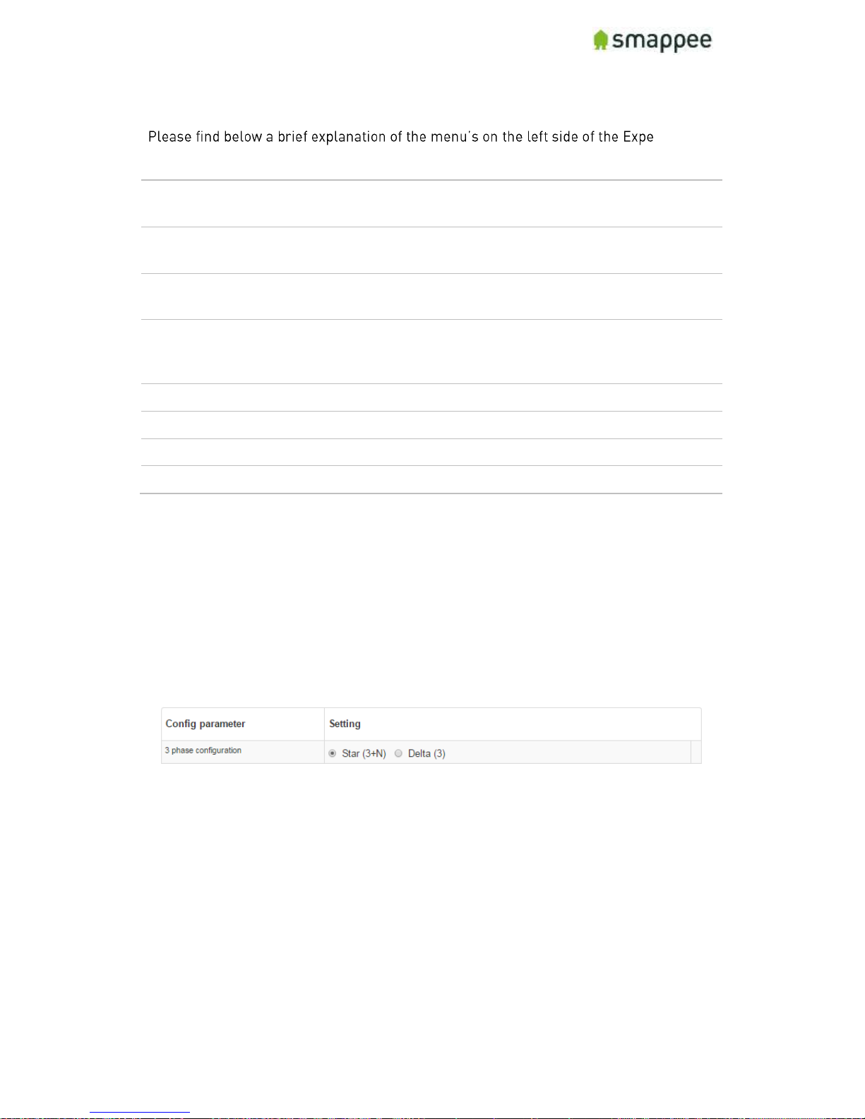
Configuration menu
In the Configuration menu, select the type of electrical network.
In most cases, "Star" is the correct selection:
three phase networks with neutral ("Star")
US Split Phase (180°, 110 V)
Only in the rare case of three-phase networks WITHOUT neutral, you need to select
"Delta".
Channel Configuration menu
The menu item "Channel configuration" allow you to configure the Current
Transformers.
For details, please refer to the previous section "Configuration Settings for " on page
23.
Page 27
Smappee Plus Installation Manual Page 27 of 32
Version 1.6.2 B, 20-06-2017, rev 4
Diagnose the Smappee in the Expert Portal
Overview
In case of complex installation or incorrect measurements, the Expert Portal provides
real-time information about specific electrical parameters of the measurements. This
information can be used to verify the installation and diagnose problems.
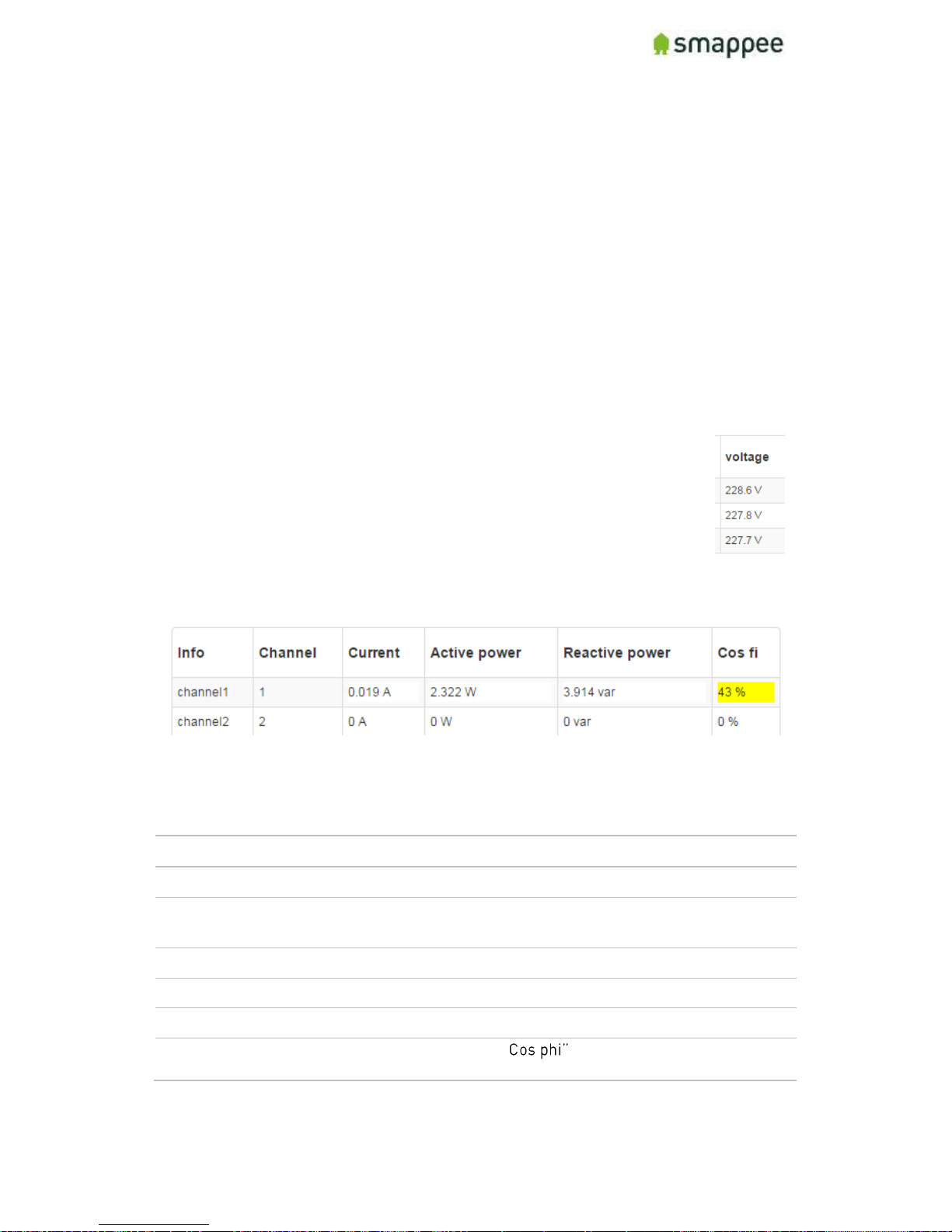
All information can be found in the Configuration menu. It shows three blocks of
information:
Voltage display per phase
Real-Time Measurements
Connected Current Transformers
Voltage Display per Phase
This block displays the voltage that is measured at each phase input. For
details, see section "Connecting the Voltage Measurement Wires" on page
8.
Important: The voltage values should be approximately the same for each
phase.
Real-Time Measurements
This block displays the real-time measurements and electrical parameters for each
input.
The next paragraph explains these parameters in more detail.
Details for Parameters
The following table explains the parameters of the Real-Time Data.
Parameter
Explanation
Info
Input on the Smappee.
Channel
Measured channel. In Smappee Plus, this is identical to the
Info column.
Current
Current measured on that CT (Ampere).
Active power
Active Power (Watt).
Reactive power
Reactive Power (var).
Cos phi
Power Factor. Note: A " of less than 60% is visually
emphasized by yellow highlighting.
Page 28
Smappee Plus Installation Manual Page 28 of 32
Version 1.6.2 B, 20-06-2017, rev 4
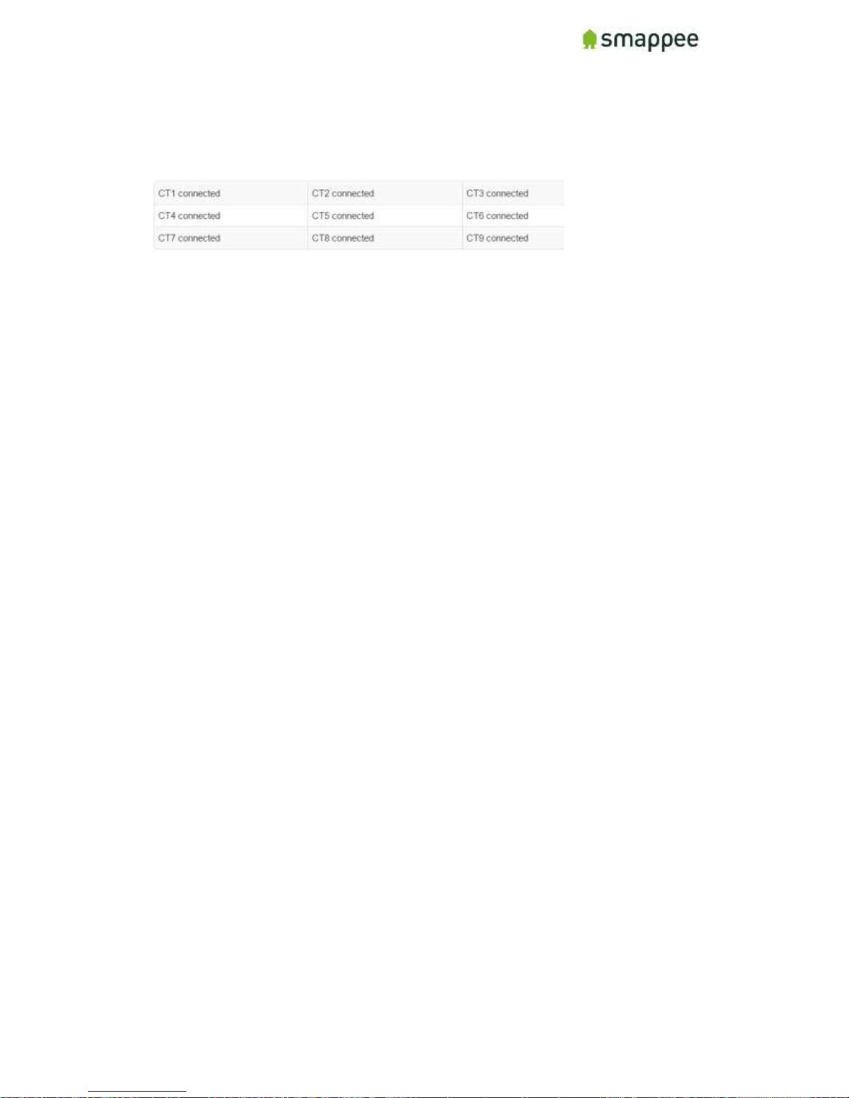
Connected Current Transformers
This block shows on which inputs there is a Current Transformers connected. It helps
to detect bad connections.
Page 29
Smappee Plus Installation Manual Page 29 of 32
Version 1.6.2 B, 20-06-2017, rev 4
Checklist for Correct Configuration
Overview
Once you reached this step, the installation is nearly complete. Before you finish work
you should carefully check the correctness of the configuration steps and of the actual
measurement values.
You need to verify that the measurements are correct. Do that before you finish
the installation.
Please perform three checks:
1. Quick Check
2. Checklist for Electrical Parameters
3. Checklist for Total Measurements
Quick Check
At this moment, the installation should meet the following criteria:
Check
Description
Details on
1.
The Smappee has been correctly powered on, according to the
instructions and checks.
page 14
2.
The Smappee is connected to the Internet and the Smappee
cloud. This is indicated by a GREEN BREATHING light.
page 16
3.
You see (some) real-time power values in the Bubbles of the App
or the Dashboard.
page 16
4.
You have configured the individual CTs, either in the App or in the
Expert Portal.
page 20
Checklist for Electrical Parameters
In the menu item Configuration, please check the following parameters.
Check
Description
1.
The Star-Delta parameter in the "Configuration menu" panel should
match the electrical installation.
2.
The three voltage values should be approximately the same for each
phase.
3.
The current measurement value of each CT should show plausible
values.
4.
The Cos fi should be above 80%.
This check should be done during periods of high consumption.
Page 30
Smappee Plus Installation Manual Page 30 of 32
Version 1.6.2 B, 20-06-2017, rev 4
Checklist for Total Measurements
Please view the real-time measurements in the Bubble-screen of the App or the
Dashboard. Run the following checks:
Check
Description
1.
The total consumption-bubble (grey) should display plausible values.
Compare the results with the main utility meter.
2.
The total production bubble (green) should display plausible values.
Compare the results with the solar inverter or batteries.
3.
When appliances turn on or off, the consumption-bubble should
change accordingly.
4.
When appliances in the sub-meter circuits turn on or off, the
consumption-bubble should change accordingly. (Make sure it does
not display the double power value).
5.
When appliances in the sub-meter circuits turn on or off, the correct
name should be displayed in the App.
6.
Perform the checks above for appliances on all three phases.
Troubleshooting
If the checks above show unexpected results, please verify the following installation
steps:
Check
Description
See
1.
The wiring of the green 8-pin connector.
page 8
2.
The installation of the Current Transformers.
page 11
3.
The correct configuration in the "Configuration" menu.
page 27
4.
The correct configuration in the "Channel Configuration"
menu.
page 23
Once all checks are successfully completed, you may finish up the installation work.
Please see the next page for the final steps.
Page 31
Smappee Plus Installation Manual Page 31 of 32
Version 1.6.2 B, 20-06-2017, rev 4
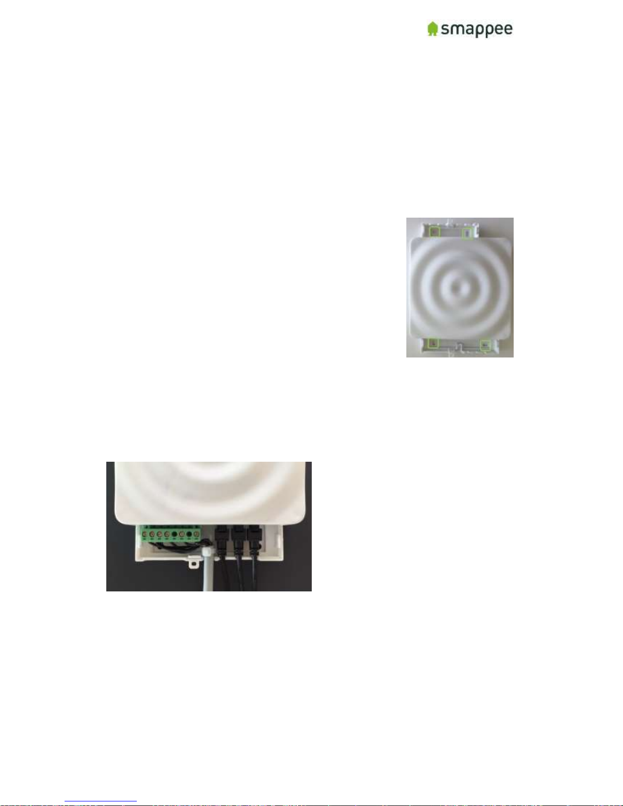
Mounting and Enclosing
Overview
Now that the voltage measure terminal and the CT cables has been installed and
connected according to local electrical regulations, you can now finish up the physical
installation.
Important: The installer is responsible to ensure proper insulation of all wires.
Wires can be routed via the breakout area in the cover cap!
Mounting
If you have found a suitable location to mount the Smappee
Plus monitor to the wall, please remove the cover caps on
each side of the Smappee Plus monitor.
You will see the mounting holes on each side made available to
you to facilitate mounting your monitor to the wall.
Cover
Mount the cover cap on the Smappee Plus to cover all electrical connections.
If you used a voltage-rated multicore cable, you can also you an internal wire strap to
fixate the cable under the covering cap.
Optionally you can use a strap or a lead seal to seal the cover cap in order to avoid any
contact with the wires.
Page 32

Smappee Plus Installation Manual Page 32 of 32
Version 1.6.2 B, 20-06-2017, rev 4
Final Remarks
Gain insights
You have now successfully completed the installation. You can now increasingly gain
insight in the energy consumption and production of the premise.
Support During Installation
In case of problems during performing an installation, please carefully read this user
manual. If this does not resolve the problem, you should contact Smappee Support.
Non-Urgent support
Please send an email to [email protected].
Urgent Support
For Smappee Partners we offer a hotline specifically for installation support while the
partner is on premise:
+32 56 38 02 56 (Europe) or +1 408 479 3748 (US).
It is available during business hours (Central European Time), 6am -11am (Eastern
Time) and 6AM - 8AM (Pacific Time).
Training
Smappee offers various training courses for installers. They can be done by video
conference or in the Smappee offices.
Feedback
We always strive to improve our products and the simplicity of installation. We are
happy to hear about your feedback.
[email protected]
 Loading...