

Smappee Infinity
Installation manual
English – Version 1.3 – June 2019

Table of contents
1. Safety instructions
1. Safety instructions
2. Smappee Infinity modularity
2. Smappee Infinity modularity
3. How to install
3. How to install
4. Planning and site preparation
4. Planning and site preparation
5. Initial setup and configuration
5. Initial setup and configuration
6. Physical installation
6. Physical installation
7. Smappee cloud connectivity
7. Smappee cloud connectivity
8. Configuration of CTs
8. Configuration of CTs
9. Validation of the installation
9. Validation of the installation
10. Troubleshooting
10. Troubleshooting
11. Smappee Bus Cable specification
11. Smappee Bus cable specification
Addendum 1 – Colour code explanation
Addendum 2 – Wi-Fi connection properties and firewall rules
Addendum 3 – Components overview
1 – Colour code explanation
dum
A
Addendum 2 – Wi-Fi connection
3
6
8
9
11
12
19
20
21
23
26
27
28
29
properties and firewall rules
Addendum 3 – Components overview
Smappee Infinity – Installation manual – English Page 2 of 29
1. Safety instructions
Safety warning
Carrying out electrical work in a home or workplace can be dangerous.
The Power Box, CT Hub, and Current Transformers are usually installed inside the
distribution board under a protective cover. The Genius can be installed both inside and
outside the distribution board.
Only certified electricians may carry out the installation, which must be in accordance with
the national safety regulations.
Safety precautions
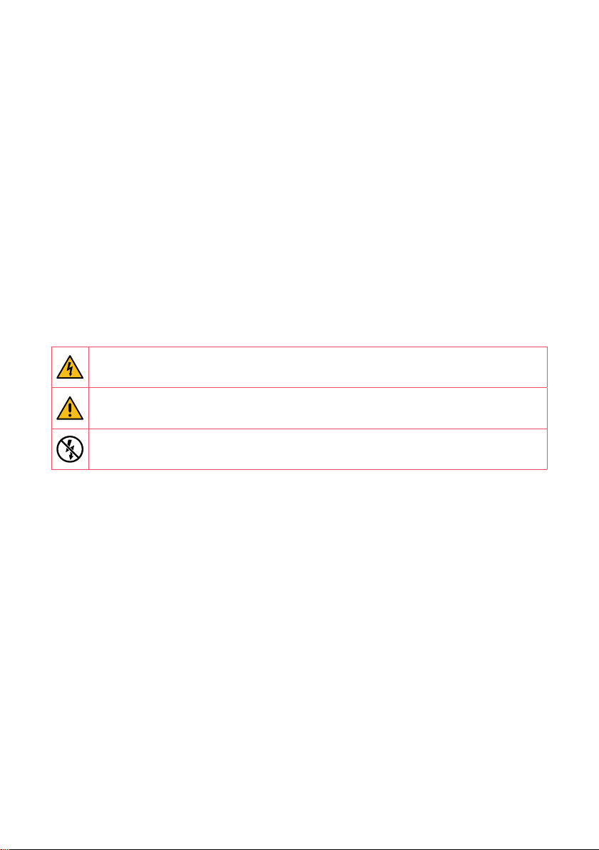
CAUTION: Risk of electric shock.
CAUTION: Refer to the accompanying documentation whenever you see this
symbol.
DO NOT clamp or pull out NON-INSULATED conductors carrying DANGEROUS
VOLTAGE which could cause an electric shock, burns, or arc flash.
Please observe the following safety precautions to avoid potential electric shock, fire, or
personal injury:
• Use this product only for its intended purpose.
• Use the product indoors only.
• Only mount the power cable in a sealed enclosure.
• Locate a free fuse or install an additional fuse of at least 6A for the protection of the Power
Box. Connect the power cable according to the connection diagram, see next pages.
• The circuit breaker acts as the disconnect device and must meet IEC 60947-2
• Do not open the equipment or touch any of its electronic circuitry.
• Do not attempt to open, repair, or service any parts.
• Only use the cables delivered with the product.
• Do not use the product if damaged.
• Do not use damaged current transformers or cables.
• Do not immerse the product in water or any other liquids.
• Do not expose the product to heat, flame, or extreme cold.
Smappee Infinity – Installation manual – English Page 3 of 29

Product identification
• Smappee Genius: MOD-GW-1
• Smappee Power Box: MOD-VAC-1
• Smappee CT Hub: MOD-IAC-1
• Smappee Wi-Fi Connect: MOD-GW-2
• Smappee Solid Core 3-Phase CT: MOD-IAC-2
Maintenance
• Clean the outside only with a dry, clean cloth.
• Do not use abrasive agents or solvents.
Responsibility
• Assembly, connection, and use must be carried out in accordance with the installation
standards currently in force.
• The device must be installed in accordance with the instructions given in this manual.
• Failure to observe the instructions for installing this unit may compromise the device’s
intrinsic protection.
• The device must be placed in a system that complies with the applicable standards and
safety regulations of the country of installation.
• No more than two CT Hubs may be installed in one system
• Cables may only be replaced with cables of the correct rating.
Explanation of the safety symbols
The table below explains the safety symbols.
Class II equipment does not require an earth connection.
IK 06
Smappee Infinity – Installation manual – English Page 4 of 29
This device has been tested according to IEC 62262 and complies to
impact class 6. (Impact energy: 1 Joule).

Residual safety risk
• The device’s housing has IK06 impact immunity level. Therefore, it is essential that the
housing is not damaged during installation.
• When there is visible damage to the device’s housing, it is recommended to replace the
device to prevent any hazardous situation to occur.
Support
Only certified electricians or equivalent may install the Smappee Infinity.
If you have any questions, please contact your local distributor.
Vista
Level
P. vpt.com.auhttps:// W.| info@vpt.com.au E.| 287 878 1300
Smappee Infinity – Installation manual – English Page 5 of 29
Ltd Pty Technologies Power
Australia 3000, VIC Melbourne, Street, Collins 480 3,

2. Smappee Infinity
modularity
Smappee Infinity is a modular energy monitoring solution, which is designed to be easily
installed in existing and new installations. Smappee Infinity’s modular design allows you to
add additional CTs through the use of CT Hubs.
Smappee Infinity has three essential components:
• CT Hubs: These are the main components of the monitoring system. You can connect up to
4 CTs or Rogowski coils to the CT Hub to measure different currents, ranging from 50A to
1000A. This allows for accurate submetering of (a group of) appliances. Daisy chain CT Hubs
to measure different installations up to a distance of 100 meters (109 yards).
• Power Box: This is the heart of the monitoring system as it provides power to all
components. It measures the line voltage of the different connected phases and transfers
the data via RS 485.
• Genius: The gateway between the monitoring system and the Smappee Cloud, ensuring
secure data storage from different components. The possibilities of communication to
cloud are Ethernet, Wi-Fi, or 3G/4G Cellular (USB dongle). It also interacts with third-party
components, Smappee Gas & Water and Smappee Switch.
Smappee Infinity – Installation manual – English Page 6 of 92

A typical Smappee Infinity setup consists of one Power Box, one Genius or Wi-Fi Connect,
CTHubs, and CTs. The different components communicate through the Smappee Bus.
The Smappee Infinity is configured through the Smappee Energy Monitor mobile app (which
you can download from the Apple App store or Google Play store). The real-time and historical
monitoring data are accessible for visualisation and analysis purposes.
Smappee Infinity can easily be integrated into any energy, home, and building management
system through several protocols such as MQTT, REST. These protocols publish real-time
measurements, events, and historical data and allow you to control your Smappee Switch
devices.
Smappee is not only a monitoring solution but also an energy traffic controller. This
functionality allows automatic interaction with the energy traffic within the installation, which
is based on predefined logic embedded in the Smappee. A basic example of this functionality is
the use of the Smappee smart plug (Smappee Switch), which allows the intelligent switching of
appliances based on the real-time load monitoring following standard processes (scenes) that
can easily be set up via the mobile app.
Smappee Infinity – Installation manual – English Page 7 of 29

3. How to install
The installation procedure consists of the following steps:
Planning and site preparation: To determine the complete monitoring solution.
1
Initial setup and configuration: The creation of a location, its properties, and the
2
loads to be measured.
Physical installation: The physical installation of all the Infinity components.
3
Smappee cloud connection: The selection of internet connectivity and configuration.
4
Configuration of CTs
5
Validation of the installation: Checking the accuracy of live power values.
6
This procedure is done with the Smappee Energy Monitor mobile app.
Smappee Infinity – Installation manual – English Page 8 of 29

4. Planning and site preparation
The first step is to determine the complete monitoring solution. This consists of listing all
the loads that need to be measured, their properties, and the required hardware (Smappee
and others).
The checklist provided helps you to determine all necessary technical information for the
next steps and also to collect all the necessary hardware.
General architecture - what is to be monitored
Single or multiple metering locations: Where are the fuse boxes or appliances to be
monitored? (Location inside the building, distances between them, etc.)
Total load (main service): Yes/no?
Specific appliances? (e.g. HVAC, Heat pump, EV, Solar, etc.). Are they fused separately or
are they powered by a wall socket & plug?
Circuits (main sockets, lighting area, etc.)
Details
Topology: Verify the mains voltage – single phase (1P), three-phase 3P+N (3*400) or 3P
(3*230)
How are the total load, solar, circuits, and/or appliances fused?
Phases of each measured load (circuits and appliances): Single-phase, three-phase,
3P+N (3*400V) or 3P (3*230V), voltage, frequency, power, amps
Cross-sectional area or diameter of the wiring
How will a stable internet connection be provided to the energy monitor: Wi-Fi, Ethernet,
or 3G/4G cellular network?
Tools (not included)
Multimeter
Screwdrivers
Wire stripper
Flashlight
Needle-nose pliers
Wire cutter
Optional: drill, drill bits and screws
Smappee Infinity – Installation manual – English Page 9 of 29

Supplies (not included)
Cable ties
Single or three-phase circuit breaker (fuse for Smappee Power Box only)
Ethernet cable in the case of wired communication
External Smappee Wi-Fi antenna in the case of low Wi-Fi signal
3G/4G Dongle in case of cellular communication
Smappee Infinity – Installation manual – English Page 10 of 29

5. Initial setup and configuration
The first step of the Smappee Infinity installation is creating a location and defining the
measured loads and their properties. The location defines where the Smappee will be
installed (e.g. house, store, or site address).
This procedure is done with the Smappee Energy Monitor mobile app.
Remarks
• The Smappee App will guide you through the various steps to fill in all the required
information.
Steps
• Log in to the Smappee App with the corresponding Smappee username or create a new
account.
• Create a new location.
• Follow the steps shown in the mobile app.
To add a new location under the same user account in the mobile app,
go to Profile > Your Locations > Add a new location.
Smappee Infinity – Installation manual – English Page 11 of 29

6. Physical installation
This procedure describes the required steps for the physical installation of the Smappee Infinity.
WARNING: For safety purposes, it is necessary to power off the installation
before proceeding with the physical installation.
Steps
Locate a free fuse or install an additional fuse of at least 6A for the protection of the
1
Power Box.
Connect the power cable according to the connection diagram, see next pages.
2
Mount the Power Box and connect the power cable.
3
Mount the Genius.
4
Connec t the cur rent t ran sfor mer s (CTs) and CT Hub(s). Keep in m ind that the ar ro w
5
indicated on the CT (K > L) has to point in the direction of the current flow.
Connect the installed CTs to their corresponding CT Hub.
6
Make the following interconnections:
7
a. The first CT Hub to Port A of the Power Box using the supplied Smappee Bus cable.
b. Connect all the CT Hubs with the supplied Smappee Bus cable or a custom twisted-
pair RJ10 cable.
c. Plug the supplied bus termination plug in the free port of the last CT Hub.
d. Connect Port B of the Power Box to Port B of the Genius using the (longest)
supplied Smappee Bus cable or a custom twisted-pair RJ10 cable.
In a multi-phase environment, all phases must be connected to the Smappee
Power Box according to the topology. This means that the appropriate wires of
the power cable must be connected to their respective phases (L1, L2, L3).
Label the current transformers
on the clamp and connector
side to enhance visualisation.
Smappee Infinity – Installation manual – English Page 12 of 29

The arrow indicated on the
CT (K > L) must point in the
direction of the current flow.
Mount the supplied bus
termination plug in the free
port of the last CT Hub.
You can use a custom RJ10 cable instead of the standard Smappee Bus cable. The
RJ10 must be a twisted pair cable. Pins 1 & 4 and Pins 2 & 3 must be twisted pairs.
See the Smappee Bus cable specification in section 11.
Smappee Infinity – Installation manual – English Page 13 of 29

Connection diagram – 1P (1*230V)
Brown – L1
Blue – Neutral
REMARK: The above wiring and colour scheme is indicative. National regulations
must be respected. Wiring for Europe must be at least 1mm
2
/ 600 V and
protected by a 6A circuit breaker.
Smappee Infinity – Installation manual – English Page 14 of 92

Connection diagram – 3P+N (3*400V)
Brown – L1
Black – L2
Grey – L3
Blue – Neutral
REMARK: The above wiring and colour scheme is indicative. National regulations
must be respected. Wiring for Europe must be at least 1mm
2
/ 600 V and
protected by a 6A circuit breaker.
Smappee Infinity – Installation manual – English Page 15 of 92

Connection diagram – 3P (3*230V)
Brown – L1
Black – L2
Grey – L3
REMARK: The above wiring and colour scheme is indicative. National regulations
must be respected. Wiring for Europe must be at least 1mm
2
/ 600 V and
protected by a 6A circuit breaker.
Smappee Infinity – Installation manual – English Page 16 of 92

Connection diagram – 2P+N (2*120V)
Black – L1
Red – L2
White – Neutral
Typical for the America’s region
REMARK: The above wiring and colour scheme is indicative. National
regulations must be respected. Wiring for the Americas region must be at least
18AWG / 600 V UL-style 1015 and protected by a 6A circuit breaker.
Smappee Infinity – Installation manual – English Page 17 of 92

Connection diagram – 3P+N (3*208V)
Black – L1
Red – L2
Blue – L3
White – Neutral
Typical for the America’s region
REMARK: The above wiring and colour scheme is indicative. National
regulations must be respected. Wiring for the Americas region should be at
least 18AWG / 600 V UL-style 1015 and protected by a 6A circuit breaker.
Smappee Infinity – Installation manual – English Page 18 of 29

7. Smappee cloud connectivity
During start-up, the Smappee Genius will check which internet connectivity is used.
Option A – Connection through Ethernet: The internet connection will be established
automatically. The light on the Smappee Genius will display a steady green colour when ready.
Option B – Connection using Wi-Fi:
• The Smappee Genius will open its hotspot, which allows configuring the Wi-Fi network
and password.
• The Smappee Genius will emit a flashing blue colour when the hotspot can be selected
in the list of available Wi-Fi networks on your smartphone. Please note that it can take a
few minutes before the hotspot is open.
• Make sure your mobile data (3G/4G) is switched OFF on your smartphone before proceeding.
• For more details about the Wi-Fi properties, please see Addendum 2.
Option C – Connection through a 3G/4G cellular network: The internet connection will be
established automatically. Insert the 3G/4G USB Dongle before power-up. The light on the
Smappee Genius will turn solid green when the 3G/4G connection is ready.
Resetting the Wi-Fi: If the Smappee has to be connected to another Wi-Fi
network or the authentication password has to be changed, select in the
Smappee App Profile > Your Smappee Monitors > Smappee Infinity > Infinity
components > Smappee Genius > Change your Wi-Fi settings and follow the
steps in the app.
Smappee Genius reset button:
Press using a small pin.
Factory reset: Carry out a factory reset when you re-install a Smappee Infinity
monitor at another location or when you want to start with the factory settings.
Press the reset button of the Genius with a small pin until the light turns blue,
after approximately 20 seconds. During this process, the Genius will first emit a
purple colour, then a yellow colour, then no colour, and finally a blue colour.
Smappee Infinity – Installation manual – English Page 19 of 29

8. Configuration of CTs
In this procedure, the initial setup and configuration are linked to each physical CT.
Proceed in the Smappee Energy Monitor mobile app and follow the steps as shown.
Smappee Infinity – Installation manual – English Page 20 of 29

9. Validation of the installation
Once the installation is complete, it is good practice to validate the correct operation of the
monitoring solution.
You should check that all CTs are operational and measuring the correct power values.
If loads are being measured, this does not automatically mean that the power values are
correct. Incorrect line voltage and current mapping could lead to incorrect power values
and wrong monitoring data.
To check the correct operation of the Smappee Infinity, Smappee provides real-time values
of all measured loads. You can access these real-time values with the mobile app or via
the Smappee Dashboard.
There are two options for visualising real-time values:
1. The Smappee App reports real-time active power values for each input individually.
2. The Smappee Dashboard reports real-time the active and reactive power, line & phase
voltage, power factor, and current of each input: https://dashboard.smappee.net – see
Live electricity values card.
Real-time values in the Smappee App: go to Profile > Your Smappee monitors >
Smappee Infinity > Load Configuration.
The details of each measured load, such as the used CT Hub input and the
phase mapping properties, are accessible under Load Configuration in the
Smappee App.
Real-time values in Smappee Dashboard:
https://dashboard.smappee.net/board/Electricity
Smappee Infinity – Installation manual – English Page 21 of 29

Use a digital multimeter to
determine which phase powers
the different loads. Please note
that the colour code inside the
fuse box and/or phase numbering
may be incorrect.
0 volt is measured when both loads are
on the same phase.
Smappee Infinity – Installation manual – English Page 22 of 29

10. Troubleshooting
Problem Possible cause Possible resolution
The Smappee Infinity does
not switch on.
One or more CT Hubs are not
available in the mobile app.
No real-time measurements
of the connected CTs.
During installation: the
Smappee App states that the
serial number of the Genius
is invalid.
The power cable is connected
incorrectly to the fuse.
Fuse is not switched on Switch on the fuse.
RJ10 cable is not inserted in
the correct port of the Power
Box and Genius.
The power cable connector
is not inserted in the Power
Box.
RJ10 cables between CT
Hubs are not connected
properly.
CT is not connected properly
to the CT Hub.
CT is not closed correctly. Close the CT correctly.
The Genius has already been
installed at another location.
Verify that the power cable is
connected according to the
connection diagram.
The Genius and Power Box
are to be interconnected via
Port B.
Connect the power cable to
the Power Box.
Check that the CT bus is
inserted in Port A of the
Power Box and all CT Hubs
are connected using RJ10
cables. Insert the bus
termination plug in the open
port of the last CT Hub.
Check that all CT Hubs have
a green flashing light.
Check the connector of the
CT into the CT Hub.
Carry out a factory reset.
Keep the reset button of
the Genius pressed in for
approximately 20 seconds
until the Genius is blue.
Restart the installation
procedure.
Smappee Infinity – Installation manual – English Page 23 of 29

The light of the Genius
flashes red.
The light of the Genius is
blue.
The light on the Genius
flashes blue after startup
with an Ethernet connection.
The monitor had a previously
working internet connection
but has now lost its
Restart the Genius by
unplugging the RJ10 cable
and plugging it back in.
connection to the internet.
If restarting does not solve the
issue, carry out the following
procedure when using a Wi-Fi
connection: keep the reset
button of the Genius pressed
for approximately 10 seconds
until the light of the Genius is
yellow. Select in the Smappee
App Profile – Your Smappee
Monitors – Smappee Infinity
– Infinity components –
Smappee Genius - Change
your Wi-Fi settings and follow
the steps in the app.
If restarting does not solve the
issue, carry out the following
procedure when using an
Ethernet or 3G/4G connection:
Check if the Ethernet cable
or 3G/4G Dongle provide a
working internet connection.
Plug in the Ethernet cable or
3G/4G Dongle firmly in the
Genius.
Smappee has not yet started. Wait for 5 minutes.
The Genius is unable to start. Restart the Smappee Genius
by unplugging the RJ10 cable
and plugging it back in, and
wait 5 minutes. If the problem
persists, contact support.
The Ethernet cable is not
connected correctly.
Check Ethernet cable
connection and restart the
Genius by unplugging the RJ10
cable and plugging it back in.
Smappee Infinity – Installation manual – English Page 24 of 29

The light of the Genius is red
after startup with an Ethernet
connection.
The light of the Genius
flashes red after startup with
an Ethernet connection.
CT Hub is not recognised
during installation.
The main feed measurement
values are incorrect.
The Ethernet cable is not
connected correctly.
Check Ethernet cable
connection and restart the
Genius by unplugging the RJ10
cable and plugging it back in.
Internet connection is down. Check and solve the internet
connection and restart the
Genius by unplugging the RJ10
cable and plugging it back in.
A firewall blocks outgoing
communication.
Smappee had a working
internet connection, but the
connection was lost.
Check the firewall rules. For
details, see Addendum 2
Check and solve the internet
connection and restart the
Genius by unplugging the RJ10
cable and plugging it back in.
Internet connection is down Check and solve the internet
connection and restart the
Genius by unplugging the RJ10
cable and plugging it back in.
Smappee Bus A (RJ10 cables
between CT Hubs) is not
connected correctly.
Check that all required RJ10
cables are connected and
the bus termination plug is
plugged in the free port of the
last CT Hub. A green blinking
LED light at a rate of 1 blink
per 3 seconds is visible on
input A of each CT Hub when
the connection is operational.
Check the LED blinking
rate on the Power Box.
When the LED is blinking
once every second, there
is a communication error
between the CT Hubs and the
Power Box.
Check that the CT Hubs are
connected to port A of the
Power Box and the Genius to
port B. Carry out a restart.
Check if the CT Hub LED on
input A is blinking. If not,
remove and exchange the CT
Hub and carry out a restart.
In the case of a custom RJ10
cable, check the operation
of the RJ10 cable and review
the Smappee Bus cable
specification in section 11.
Power Connectors L1, L2,
L3 do not correspond with
the current phases (phasemapping).
Use a multimeter to check
that the voltage L1, L2, L3
corresponds with the Load
Configuration of the Grid
(phase setting). See the tips
in the chapter “Validation of
the installation”.
Smappee Infinity – Installation manual – English Page 25 of 29

11. Smappee Bus cable specification
Custom RJ10 cables can be used for installations. Please note the following specifications
and limitations:
• A cable containing 2 unshielded twisted pairs
• Straight connection: pin 1 to 1, etc.
• Unshielded
• Pins 1 & 4 Pins 2 & 3 must be twisted pairs
• Characteristic impedance of 100 ohm
• AWM style 2835: 60° / 30V – 24 AWG
• The maximum length of each bus is 100 m (109 yards):
• The total length of the CT Hub bus must be no more than 100 metres (109 yards).
• The length of the Genius-Power Box bus is also no more than 100 metres (109 yards).
(109 yards)
(109 yards)
WARNING: The bus termination plug must be plugged into the output of the last
CT Hub. And is supplied in Port A of the Power Box.
Smappee Infinity – Installation manual – English Page 26 of 29

Addendum 1 – Colour code explanation
Genius
Green breathing
Blue Steady
Green Steady
Blue Flashing
Red Steady
Red Flashing
Yellow Steady
Yellow Flashing
All good. The Genius is working correctly.
The Genius is starting up. This may take up to 5 minutes. The light may
briefly go off during that time.
Network connection is successful, but the Genius is not yet activated on
a location.
Ethernet: Connected to the local network.
Wi-Fi: Connected to the Wi-Fi and the local network (i.e. the Wi-Fi
password is correct)
3G/4G Dongle: Connected to the 3G/4G network.
The Genius is ready to be connected to the local Wi-Fi network.
The Genius has no connection to the internet during startup. Connection
issue.
The Genius had a working internet connection but has lost its
connection to the Smappee cloud.
The Wi-Fi hotspot access point has been activated to allow the Genius
to reconfigure the Wi-Fi settings.
Smappee is trying to open a Wi-Fi hotspot access point. Please wait a
few seconds. The light will turn to a steady yellow in a few moments.
CT Hub
LED at input A, B, C or D
3 pulses per second, on any of the inputs A, B, C, D.
LED at input A
Short pulse every 3 seconds
LED at input A
One pulse every second
LED at input A
2 pulses per second
Indication of the selected CT input during CT
configuration.
CT Hub is switched on.
Communication error.
Configuration problem.
Power Box
LED between port A and B is pulsing once every 5 s
LED between port A and B is pulsing once
every 1 second
Smappee Infinity – Installation manual – English Page 27 of 29
Power Box is powered on and operating correctly.
Smappee Bus A error

Addendum 2 – Wi-Fi connection
properties and firewall rules
Wi-Fi Connection properties
• 2.4 GHz Wi-Fi required, preferably with automatic channel selection
• Networks without DHCP ser ver are not supported
• WPA or WPA2 encryption mandatory
• Networks without security are not supported (!)
• SSID must be visible and should not be hidden during installation. SSID must NOT
contain the following characters: é,ç,è,ä,/ \, “, à î ô ï
• Allowed special characters for the Wi-Fi password: #$%@?/ \
• MAC filtering must not be active on the router
• Your firewall should allow Smappee to create outbound secure HT TP connections
• The maximum number of characters for the WPA2/PSK is 20.
The DHCP of your router assigns the IP address of your Smappee.
Firewall rules
If you use a firewall, you should apply the following firewall rules to allow traffic from and
to the Smappee:
• Inbound rules: any IP - disabled, any port - disabled
• Outbound rules: any IP - allowed, any port - allowed
Smappee Infinity – Installation manual – English Page 28 of 29

Addendum 3 – Components overview
Hardware
Component Article number
Smappee Genius I1- G W -1
Smappee Wi-Fi Connect I1-GW-2
Smappee Power Box I1-VAC-1 (I1-VAC-1-U S for US)
Smappee CT Hub I1- I A C -1
Smappee Solid Core 3-Phase CT I1-IAC-2
Wall mounting plate kit (8 pieces) AC-IMPW-8
DIN mounting plate kit (4 pieces) AC-IMPD-4
Smappee Bus cable – 40 cm (15.75 inches) AC-IBC40
Smappee Bus cable – 150 cm (59 inches) AC-IBC150
Smappee Bus cable set – 100m (109 yards) - 50 RJ10 connectors AC- IBCS-10 0m
You can also use a custom RJ10 cable. See Smappee Bus cable specification in
section 11.
Current Transformers
Standard Article number Rogowski Article number
50A AC-CT-50A
100A AC-CT-100A 1000A AC-RSCT-1000A
200A AC-CT-200A
400A AC-CT-400A
800A AC-CT-800A
50A AC-CT-S-50A
100A AC-CT-S-100A
200A
400A AC-CT-S-400A
1000A AC-RSCT-1000A
Smappee Infinity – Installation manual – English Page 29 of 29
AC-CT-S-200A
400A AC-RSCT-400A
Contact Smappee if you need to measure
higher current values.
 Loading...