

USB-1000 Series Multi-Function
Data Acquisition Devices
USB-1252/USB-1252A
User Manual
Rev: C
Smacq Technologies Co., Ltd.
www.smacq.com
www.smacq.cn

2
Contents
1. Product Overview .......................................................................................................................... 4
1.1. Overview ................................................................................................................................. 4
1.2. Block Diagram ......................................................................................................................... 4
1.3. Product Features ...................................................................................................................... 4
1.4. Product Specifications ............................................................................................................. 5
Analog Input ................................................................................................................... 5
Digital IO ........................................................................................................................ 6
Counter ............................................................................................................................ 6
Bus Interface ................................................................................................................... 6
Power Requirements ....................................................................................................... 6
Other Specifications ........................................................................................................ 6
2. Description on Appearance and Signal Connection .................................................................... 8
2.1. Appearance .............................................................................................................................. 8
2.2. Signal Connection ................................................................................................................. 10
Connecting Analog Input Signal ................................................................................... 10
Connecting Digital IO Signals and Counter .................................................................. 12
2.3. USB Cable Reinforcement .................................................................................................... 14
3. Installation and Testing ............................................................................................................... 14
3.1. Driver Installation .................................................................................................................. 14
3.2. Hardware Installation ............................................................................................................ 15
4. Analog Input ................................................................................................................................. 16
4.1. Overview ............................................................................................................................... 16
4.2. Input Range Description ........................................................................................................ 17
Single-Ended Mode ....................................................................................................... 17
Differential Mode .......................................................................................................... 17
4.3. Description on Multi-Channel Scanning ............................................................................... 17
Sampling rate ................................................................................................................ 17
Input Ranges ................................................................................................................. 17
4.4. Trigger Sources ...................................................................................................................... 18
4.5. Analog Input Mode ................................................................................................................ 18
4.6. Floating Signal Source........................................................................................................... 19
Using Differential Connections for Floating Signal Source .......................................... 19
Using Non-Referenced Single-Ended (NRSE) Connections for Floating Signal Sources
...................................................................................................................................... 22
Using Referenced Single-Ended (RSE) Connections for Floating Signal Sources ....... 23
4.7. Ground-Referenced Signal Source ........................................................................................ 24
Using Differential Connections for Ground-Referenced Signal Source ....................... 24
Using Non-Referenced Single-Ended (NRSE) for Ground-Referenced Signal Sources
...................................................................................................................................... 25
Using Referenced Single-Ended (RSE) for Ground-Referenced Signal Sources .......... 26
5. Digital IO ...................................................................................................................................... 26
5.1. Overview ............................................................................................................................... 26

3
5.2. Connecting Digital I/O Signal ............................................................................................... 26
6. Counter ......................................................................................................................................... 27
6.1. Overview ............................................................................................................................... 27
6.2. Event counter ......................................................................................................................... 28
6.3. Period/Positive/Negative Pulse Width Measurement ............................................................ 28
6.4. Connecting Counter Signals .................................................................................................. 28
7. Programming Instructions .......................................................................................................... 29
7.1. Overview ............................................................................................................................... 29
7.2. Basic functions ...................................................................................................................... 29
FindUSBDAQ() ............................................................................................................ 29
OpenDevice() ................................................................................................................ 30
CloseDevice() ................................................................................................................ 30
ResetDevice() ................................................................................................................ 30
7.3. Analog Input Related Functions ............................................................................................ 30
SetUSB1AiRange() ....................................................................................................... 30
SetSampleRate() ............................................................................................................ 31
SetChanMode() ............................................................................................................. 31
SetChanSel() ................................................................................................................. 31
SetSoftTrig() ................................................................................................................. 32
7.4. Digital IO Related Functions ................................................................................................. 32
SetDioOut() ................................................................................................................... 32
7.5. Counter Related Functions .................................................................................................... 33
SetCounter() .................................................................................................................. 33
StartCounter() ................................................................................................................ 33
ClearCounter() .............................................................................................................. 33
7.6. Read Data Control Functions................................................................................................. 34
StartRead() .................................................................................................................... 34
StopRead() .................................................................................................................... 34
GetAiChans() ................................................................................................................ 34
GetDioIn() ..................................................................................................................... 35
GetCounter() ................................................................................................................. 35
GetCtrTime() ................................................................................................................. 35
ClearBufs() .................................................................................................................... 36
TransDioIn() .................................................................................................................. 36
7.7. Error Code ............................................................................................................................. 36
7.8. Instructions for LabVIEW Developecr .................................................................................. 37
7.9. Instructions for MATLAB Developer .................................................................................... 37
8. Ordering Information .................................................................................................................. 38
9. Service and Warranty .................................................................................................................. 39
10. Revision History ........................................................................................................................... 40
4
1. Product Overview
1.1. Overview
The new USB-1000 series multi-function data acquisition (DAQ) device provides a new option
for convenience and quick start of data acquisition application. Its exquisite shape provides super
portable and very flexible installation.
USB-1000 series DAQ devices provide 12-bit, up to 500kS/s sampling rate, and up to 16 analog
signal acquisition channels. You can set the range as 0~10V or ± 5V via software.
With 16 digital input/output channels and 4 counter channels, USB-1000 series DAQ device offers
you the flexibility to build automatic control system of any size.
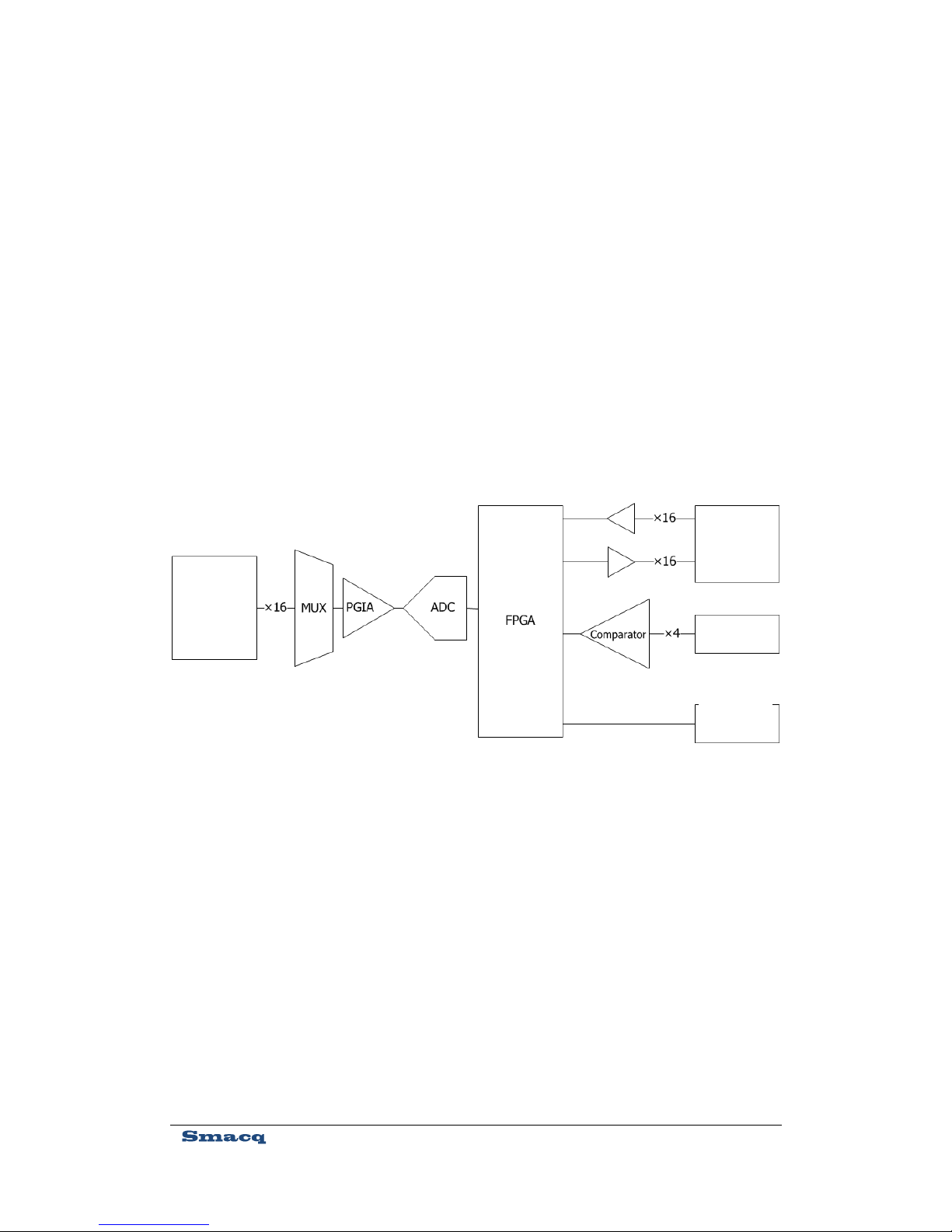
1.2. Block Diagram
1.3. Product Features
12-bit analog input (AI) resolution.
Up to 500kS/s analog input (AI) sampling rate. (Up to 200kS/s with multiple channels
enabled.)
Sampling period configurable by steps of 20ns.
Up to 16 single-ended AI channels or 8 differential AI channels configurable via
software.
Figure 1. Block Diagram of USB-1000 series DAQ device
Digital IO
Counter
USB bus
AI
5
0~10V or ± 5V configurable via software.
Onboard 16K sampling point FIFO buffer.
Up to 16 digital input (DI) channels and 16 digital output (DO) channels.
Up to four 32-bit counter channels.
LabVIEW, Visual Studio and MATLAB development support.
1.4. Product Specifications
The following product specifications, unless otherwise stated, are measured at the temperature of
25°C and the humidity of 40%.
Analog Input
Number of AI Channels
16 single-ended channels or 8 differential channels
configurable via software.
Synchronous Sampling
No
AI Resolution
12-bit
Converter Type
SAR
Sampling Rate
Single-channel acquisition: 500kS/s maximum
Multiple-channel acquisition: 200kS/s maximum
Timing Resolution
20ns
AI FIFO Buffer
16k sampling point
Range
0~10V or -5~5V configurable via software.
Safe Voltage
±15V, the DAQ device may be damaged if the input voltage
exceeds this safe voltage.
Input Impedance
>1GΩ (Power On)
Input Coupling Mode
DC
Trigger Mode
Software trigger
System Noise
NRSE 0~10V range: 0.15mVrms
NRSE ± 5V range: 0.3mVrms
DIFF 0~10V range: 0.2mVrms
DIFF ± 5V range: 0.4mVrms
Absolute Accuracy
NRSE 0~10V range: 2.8mV
NRSE ± 5V range: 3mV
DIFF 0~10V range: 3mV
DIFF ± 5V range: 4mV

6
Digital IO
Number of DO Channels
16
High Level Output Voltage
3.0~3.4V
Low Level Output Voltage
0~0.1V
Number of DI Channels
16
Low Level Input Voltage
3.3~5V
High Level Input Voltage
0~0.5V
Counter
Number Of Counters
4
Resolution
32-bit
Counter Measurement
Edge Count,
Counting Direction
Count Up
Maximum Input Frequency
1MHz
Bus Interface
USB Interface Specification
USB 2.0 High-Speed Interface
USB Interface Connector
USB Series Type-B Connector
Power Requirements
USB Bus Power Supply
4.75~5.25VDC
Current Consumption
About 300mA
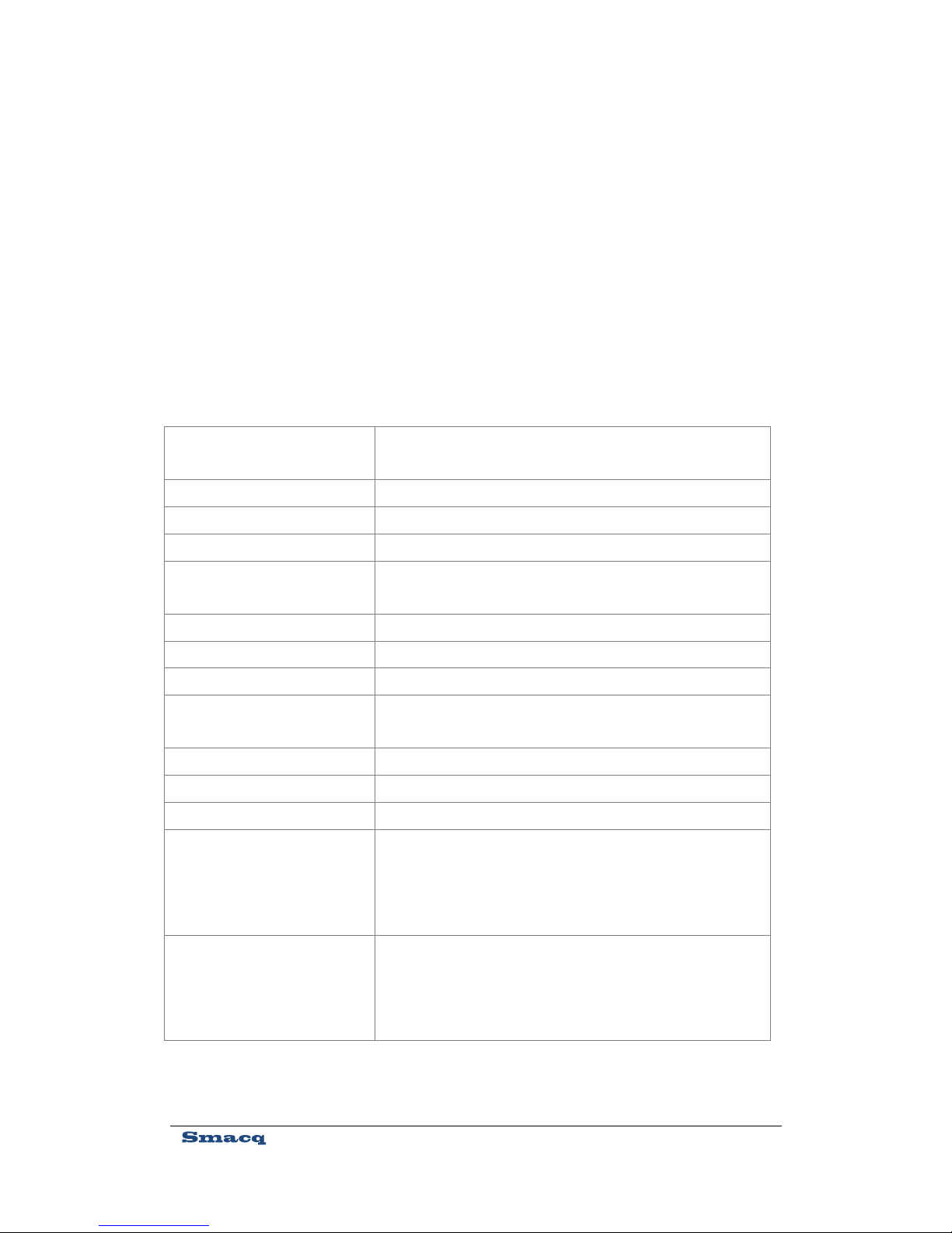
Other Specifications
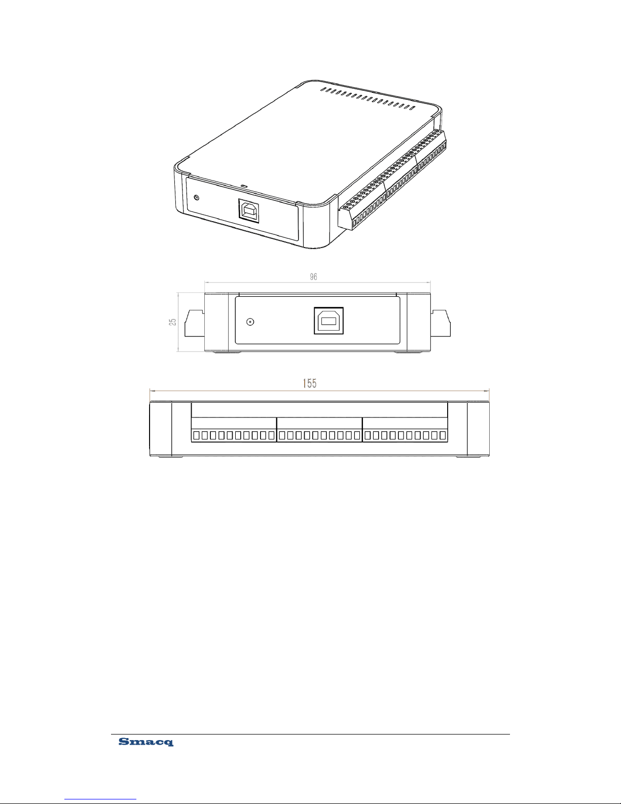
Dimensions (mm)
Without Connector: 156*102*26
With Connector:161*102*26
Weight
About 420g
Analog Channel Signal Connector
10-PIN Screw Terminal Connector
Digital IO and Counter Connector
40-PIN IDC Connector
Operating Environment
0°C ~55°C
5%RH~90%RH, Non-Condensing
Storage Environment
-40°C ~85°C

7
5%RH~90%RH, Non-Condensing

8
2. Description on Appearance and Signal
Connection
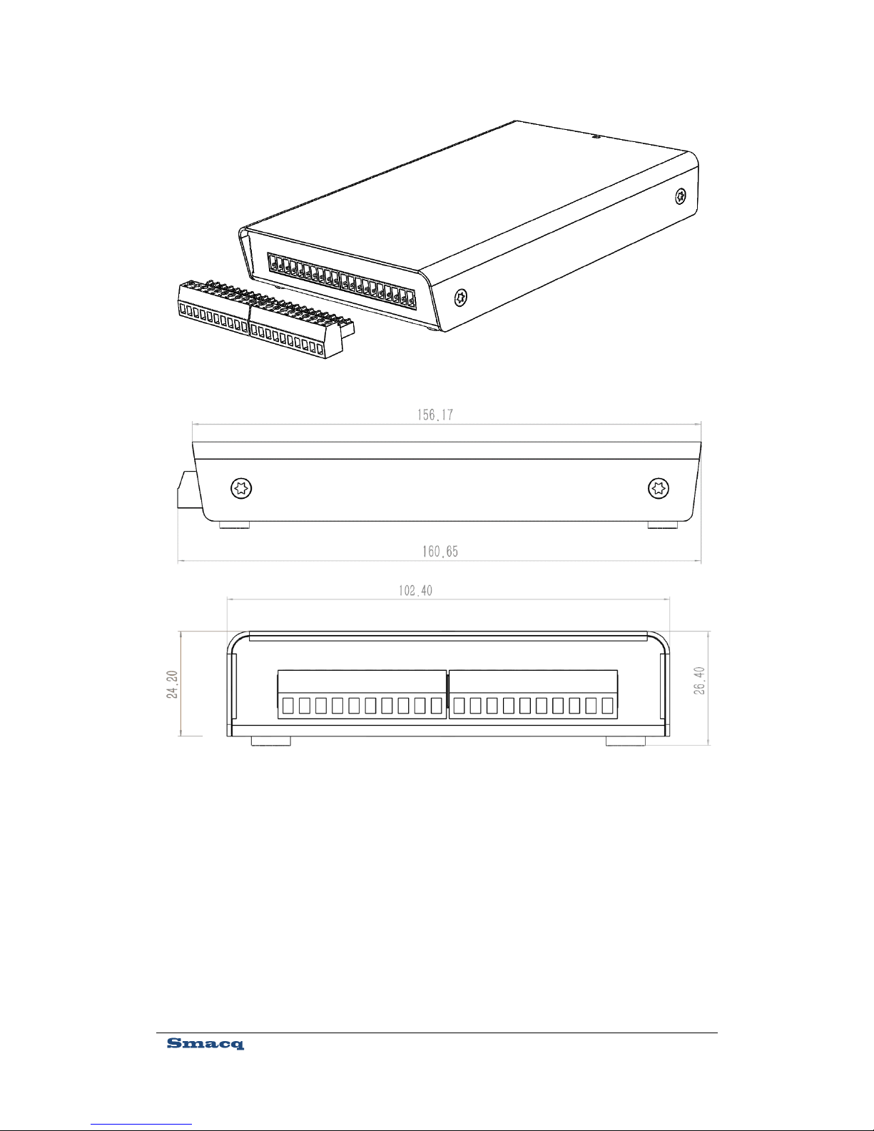
2.1. Appearance
USB-1000 series DAQ device uses metal shielding enclosure, with AI signals connected with
plug-in screw terminal connectors, digital IO signals and counter signals connected with 40-PIN
IDC connectors, and USB communication interface connected with USB series type-B connector.
Figure 2 shows the overall appearance and dimensions (in mm) of the product.
Sensors generate electrical signals to measure physical phenomena, such as temperature, force,
sound, or light. Strain gauges, thermocouples, thermistors, angular encoders, linear encoders, and
resistance temperature detectors (RTDs) are commonly used sensors.
9
Figure 2. External View of USB-1252 DAQ Device
10
2.2. Signal Connection
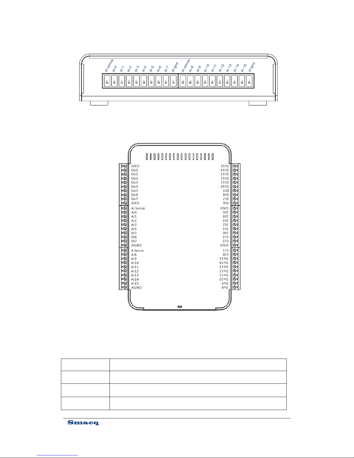
Connecting Analog Input Signal
The screw terminal connector, located in front of the DAQ device, is used for connecting AI
signals. Figure 3 and Table 1 show its pin distribution and corresponding signals. Unused AI
channels should be grounded so as to reduce system noise and achieve higher stability.
Figure 3. External View of USB-1252A DAQ Device
11
Table 1 Mapping of Pins and Signals of Screw Terminal
Name
Description
ai-sense
Reference end input for Non-Referenced Single-Ended (NRSE) signal
ai-gnd
Analog ground
ai-0
AI channel, ai0 for single ended, and ai0+ for differential
Figure 4. Pin Distribution and Corresponding Signals of Screw
Terminal Connector
Figure 5. Pin Distribution and Corresponding Signals of Screw
Terminal Connector

12
ai-1
AI channel, ai1 for single ended, and ai0- for differential
ai-2
AI channel, ai2 for single ended, and ai1+ for differential
ai-3
AI channel, ai3 for single ended, and ai1- for differential
ai-4
AI channel, ai4 for single ended, and ai2+ for differential
ai-5
AI channel, ai5 for single ended, and ai2- for differential
ai-6
AI channel, ai6 for single ended, and ai3+ for differential
ai-7
AI channel, ai7 for single ended, and ai3- for differential
ai-8
AI channel, ai8 for single ended, and ai4+ for differential
ai-9
AI channel, ai9 for single ended, and ai4- for differential
ai-10
AI channel, ai10 for single ended, and ai5+ for differential
ai-11
AI channel, ai11 for single ended, and ai5- for differential
ai-12
AI channel, ai12 for single ended, and ai6+ for differential
ai-13
AI channel, ai13 for single ended, and ai6- for differential
ai-14
AI channel, ai14 for single ended, and ai7+ for differential
ai-15
AI channel, ai15 for single ended, and ai7- for differential
Connecting Digital IO Signals and Counter
The IDC connector, located at the back of the DAQ device, is used for connecting digital IO
signals and counter signals. Figure 4 and Table 2 show its pin distribution and corresponding
signals.

13
Table 2 Mapping of Pins and Signals of Screw Terminal
Name
Reference
Direction
Description
Di0~Di15
GND
Input
DI channels
Do0~Do15
GND
Output
DO channels
Ct0~Ct3
GND
Input
Counter channels
GND
Digital ground
Figure 6. Pin Distribution and Corresponding Signals of IDC
Connector
Figure 7. Pin Distribution and Corresponding Signals of Screw
Terminal Connector

14
2.3. USB Cable Reinforcement
To prevent USB connectors from falling off accidentally, a binding band is provided to be used to
fix the USB cable to the body of the USB-1000 series DAQ devices. Refer to Figure 5 for
installation.
3. Installation and Testing
3.1. Driver Installation
If you intend to use USB-1000 series DAQ device on a PC running Windows, you need to install
the driver to make the OS recognize the DAQ device.
Here we take Windows7 operating system as an example. The driver installation steps are as
follows: (for Windows8, Windows8.1 and Windows10 operating systems, it is required to disable
the driver signature authentication during booting. For Windows XP operating system, it can be
used directly without any other settings.)
1) Open the Device Manager of the Windows operating system.
2) Right click on the device with an exclamation point
, and select Update Driver Software....
3) In the pop-up dialog box, select Browse my computer for driver software.
Figure 8. USB Cable Reinforcement

15
4) Then, choose Select from a list of device drivers on my computer.
5) Keep the default and click Next, and then click Have Disk.
6) In the pop-up dialog box, click Browse, go to the \USB-1000 Series DAQ\dirver folder
in the ResourceCD, find the Win7 folder, and then go to the x86 folder for 32-bit
operating system and x64 folder for 64-bit operating system, and finally select the
gusb.inf file, and click Open. (Windows8, Windows8.1, and Windows10 use the same
driver file as Windows7.)
7) Click OK in the Install from Disk dialog box.
8) Click Next. If a Windows security warning dialog box appears, you need to choose the
second option Always install this driver software.
9) The system starts the installation, which will take about 30 seconds. Upon the driver
installation is completed, you can see that the exclamation point in the Device Manager
disappears, as shown in Figure 6.
3.2. Hardware Installation
For connection of testing signals, refer to detailed description on connections of AI, digital IO and
counter in the subsequent sections.
After installing the driver and correctly connecting signals, you can run any one of the routines of
the USB-1000 series DAQ device in the ResourceCD. The acquired signals will be shown.
Figure 9. Device Manager Display with Driver Correctly Installed

16
4. Analog Input
4.1. Overview
With 16 AI channels, USB-1000 series DAQ device can be configured as 16 single-ended input
channels or 8 differential input channels. Figure7 shows the block diagram of analog input
function of the USB-1000 series DAQ device.
The AI block diagram of the USB-1000 series DAQ device includes the following main
components:
MUX: A multiplexer, routing and inputting the signal from the desired channel to the
instrumentation amplifier.
AI mode setting: Set AI to differential input (DIFF), Referenced Single-Ended (RSE), or
Non-Referenced Single-Ended (NRSE). Refer to Section 4.2 for detailed description on these
modes.
PGIA: Programmable gain instrumentation amplifier, used for setting input ranges.
ADC: An analog to digital converter.
AIFIFO:Data buffer FIFO.
Figure 10. Block Diagram Of Analog Input
Input Range
setting
AI mode
setting

17
4.2. Input Range Description
Single-Ended Mode
For single-ended input mode, positive input is connected to ai-n, and negative input to ai-gnd or
ai-sense. Its input range can be set to 0~10V or ±5V via the software.
Differential Mode
For DIFF Mode, positive input is connected to AI+, and negative input to AI-. Its input range can
be set to 0~10V or ±5V via the software.
The voltage from AI+ and AI- can vary in the range of -10V~10V. The actually measured voltage
value is the difference of voltage between AI+ pin and AI- pin.
When the input range is set to 0~10V, voltage range that can be measured in differential mode
shall meet the following conditions:
The voltages from both AI+ and AI- are in the range of -10V~10V, and the voltage in the range of
0V ≥ (AI+) – (AI-) ≤ 10V can be measured correctly.
When the range is set to -5V~5V, voltage range that can be measured in differential mode shall
meet the following conditions:
The voltages from both AI+ and AI- are in the range of -10V~10V, and the voltage in the range of
-5V ≥ (AI+) – (AI-) ≤ 5V can be measured correctly.
4.3. Description on Multi-Channel Scanning
Sampling rate
In multi-channel scanning applications, the PGIA will need enough settling time in switching
channels. In such case, the sampling rate can be set to 200kS/s at maximum.
Setting sampling rate higher than actually required sampling rate should be avoided, as lower
sampling rate makes the PGIA having more sufficient settling time, so that the accuracy of data
acquisition can be improved.
Input Ranges
The input range of the DAQ device should be set uniformly. In multi-channel scanning
applications, all the channels shall have a same range.

18
4.4. Trigger Sources
When USB-1000 series DAQ acquires signals via analog input, its trigger source can be set to
trigger by software or trigger by the rising edge or falling edge of digital IO input channel DIN0
port.
4.5. Analog Input Mode
The AI channel of USB-1000 series DAQ device can be configured as Referenced Single-Ended
(RSE), Non-Referenced Single-Ended (NRSE) or Differential Input (DIFF) mode. Table 3 shows
the recommended analog input modes for floating signal source and ground-referenced signal
source.
Table 3 Analog Input Mode
Analog Input
Mode
Floating Signal Sources (Not
connected to the building ground)
Ground-Referenced Signal source
Example
Ungrounded thermocouple
Isolated output signal
Battery-powered devices
Non-isolated output signal
Differential
Input
(DIFF)
Non-Referenced
Single-Ended
(NRSE)
Signal source
Signal source
Signal source
Signal source

19
Referenced
Single-Ended
(RSE)
4.6. Floating Signal Source
A floating signal source is not connected in any way to the building ground system, and instead it
has an isolated ground-reference point. Some examples of floating signal sources are outputs of
transformers, thermocouples, battery-powered devices, optical isolators, and isolation amplifiers.
An instrument or device that has an isolated output is a floating signal source.
Using Differential Connections for Floating Signal Source
Use DIFF mode for connections of floating signal sources when any of the following conditions
are met:
Two analog input channels, AI+ and AI-, are available for the signal.
The input signal is low level and a high accuracy is required.
The leads connecting the signal to the DAQ device are greater than 3m.
The input signal requires a separate ground-reference point or return signal.
The signal leads travel through noisy environments.
DIFF signal connections reduce noise pickup and increase common-mode noise rejection.
For floating signal source with impedance less than 100Ω, it is allowable to connect the negative
side of the signal to AI- and AI-GND, and connect the positive side of the signal to AI+, as shown
in Figure 8 below.
Signal source
Ground-loop
potential (VA –
VB) are added
to measured signal.
Signal source
When measuring a floating signal, make sure the negative input is
directly connected to the AGND, or indirectly through a resistor
connected to the AGND.

20
However, for floating signal source with larger impedance, this connection leaves the DIFF signal
off balance. Common-mode noise will couple onto AI+ signal instead of AI- signal. Such,
common-mode noise will appear in your measured data. In this case, connect AI- port and
AI-GND port through a bias resistor that is about 100 times the equivalent source impedance, as
shown in Figure 9. In such way, the resistor puts the differential signal nearly in balance, so that
about the same amount of noise couples onto both ends of the signal, yielding better rejection of
common mode noise.
However, for floating signal source with larger impedance, you can also use DIFF Mode using
two bias resistors, as shown in Figure 10. This fully balanced bias resistor connection offers
Figure 11 Differential Connection for Floating Signal Sources without Bias Resistor
Figure 12. Differential Connections for Floating Signal Source with Single Bias Resistor

21
slightly better noise rejection, but it has the disadvantage of loading the signal source down and
introducing gain error. If, for example, the source impedance is 2 kΩ and each of the two resistors
is 100 kΩ, the signal source load is 200 kΩ and it produces a -1% gain error.
If the floating source is AC coupled, the PGIA needs a resistor to provide DC circuit for the
positive input AI+, as shown in Figure 11.
If this AC coupled floating signal source has low impedance, choose a resistor between 100 kΩ to
1 MΩ that will neither significantly load the source nor produce offset voltage as a result of bias
current of PGIA. In this case, connect the AI- directly to AI-GND.
If this AC coupled floating source has high impedance, use the previously described Differential
Connection with Balanced Bias Resistors. Be aware that there is some gain error resulting from
balanced bias resistors.
Figure 13. Differential Connections for Floating Signal Sources with Balanced Bias Resistors

22
Using Non-Referenced Single-Ended (NRSE) Connections
for Floating Signal Sources
Use NRSE mode for connections of floating signals when all of the following conditions are met:
The input signal is high level (greater than 1V).
The leads connecting the signal to the DAQ device are lower than 3m.
DIFF input connections are recommended for greater signal integrity for any input signal that does
not meet the preceding conditions. In the single-ended modes, more electrostatic and magnetic
noise couples into the signal connections than in DIFF configurations.
Figure 12 shows the connection diagram of floating signal sources in NRSE mode. The impedance
value setting of its ground resistor is determined based on the same criterion as that in DIFF mode.
Figure 14. Differential Connections for AC Coupled Floating Sources

23
Using Referenced Single-Ended (RSE) Connections for
Floating Signal Sources
Use RSE mode for connections of signals when all of the following conditions are met:
The input signal can share a common reference point AGND with other signal using
RSE connection.
The input signal is high level (greater than 1V).
The leads connecting the signal to the DAQ device are less than 3m.
DIFF input connections are recommended for greater signal integrity for any input signal that does
not meet the preceding conditions. In the single-ended modes, more electrostatic and magnetic
noise couples into the signal connections than in DIFF configurations.
Figure 13 shows the connection diagram in of floating signal sources in RSE mode.
Figure 15. NRSE Connections for Floating Signal Sources

24
4.7. Ground-Referenced Signal Source
A ground signal source is a signal source connected to the building system ground. It is already
connected to a common ground point with respect to the device, assuming that the computer is
plugged into the same power system as the signal source. Non-isolated outputs of instruments and
devices that plug into the building power system fall into this category.
The difference in ground potential between two instruments connected to the same building power
system is typically between 1 and 100 mV, but the difference can be much higher if power
distribution circuits are improperly connected. If a grounded signal source is incorrectly measured,
this difference can appear as measurement error. Follow the connection instructions for grounded
signal sources to eliminate this ground potential difference from the measured signal.
Using Differential Connections for Ground-Referenced
Signal Source
Use DIFF mode for connections of grounded signal sources when any of the following conditions
are met:
Two analog input channels, AI+ and AI-, are available for the signal.
The input signal is low level and a high accuracy is required.
The leads connecting the signal to the DAQ device are greater than 3m.
The input signal requires a separate ground-reference point or return signal.
The signal leads travel through noisy environments.
Figure 16. RSE Connections for Floating Signal Sources

25
DIFF signal connections reduce noise pickup and increase common-mode noise rejection. DIFF
connections also allow input signals to float within the common-mode limits of the PGIA.
Figure 14 shows the connection diagram of grounded signal sources in DIFF mode.
Using Non-Referenced Single-Ended (NRSE) for
Ground-Referenced Signal Sources
Use NRSE mode for the connection of floating signals when all of the following conditions are
met:
The input signal is high level (greater than 1V).
The leads connecting the signal to the DAQ device are lower than 3m.
The input signal can share a reference point with voltage which is not AI GND.
DIFF input connections are recommended for greater signal integrity for any input signal that does
not meet the preceding conditions. In the single-ended modes, more electrostatic and magnetic
noise couples into the signal connections than in DIFF configurations.
Figure 15 shows the connection diagram of grounded signal source in NRSE mode.
Figure 17. Differential Connections for Ground-Referenced Signal Sources

26
Using Referenced Single-Ended (RSE) for
Ground-Referenced Signal Sources
For grounded signal sources, differential mode (DIFF) or Non-Referenced Single-Ended (NRSE)
connections may be used under permitting conditions. If RSE mode is used for connecting the
signal, potential difference may exist between the ground of the signal source and the ground of
the DAQ device. This difference may produce measurement errors, as described in Table 3.
5. Digital IO
5.1. Overview
The USB-1000 series DAQ device contains 16 digital input DIN channels and 16 digital output
D
OUT
channels. GND is the ground-reference signal of digital IO port.
The digital input DIN channel is compatible with 0~5V level signal. 2~5V is determined as high
level, and 0~0.5V as low level.
Digital output D
OUT
channels output high level of 3.3V, and output low level of 0V.
5.2. Connecting Digital I/O Signal
Figure 16 shows the connection diagram of digital I/O signals. When using digital output D
OUT
Figure 18. NRSE Connections for Ground-Referenced Signal Sources

27
signals, it is desirable to use low-level driving mode as much as possible for the purpose of
reducing the power burden of the digital output channels of your DAQ device.
6. Counter
6.1. Overview
USB-1000 series DAQ device has 4 counter channels, with input signal voltage up to 5V. GND is
the ground-reference signal of counter channels. The counter can be configured as any of the
following three functions:
Event counter
Period measurement
Positive pulse width measurement
Negative pulse width measurement
Figure17 shows the block diagram of the counter function of USB-1000 series DAQ devices.
Since the counter channel is added with a comparator,USB-1000 series DAQ devices can be used
to count or measure the periods of sine waves.
Figure 19. Digital I/O Signal Connection

28
6.2. Event counter
In event counter applications, the counter channel of the DAQ device is used as an event counter.
You can configure the counter to count rising or falling edges of the Ct port.
You can configure the event counter counting up, but not counting down, that is, the value of the
event counter is accumulated in the order 0, 1, 2, 3, 4, and 5 depending on the number of pulses
received.
6.3. Period/Positive/Negative Pulse Width Measurement
You can configure the counter channel of the DAQ device to measure period/positive pulse
width/negative pulse width via the software.
In period measurement applications, the DAQ device measures the period between two rising
edges from the comparator and save it in the results of the corresponding counter channel, with a
time accuracy of 40ns.
In positive pulse width measurements, the DAQ device measures the period between one rising
edge and the following falling edge from the comparator and save it in the results of the
corresponding counter channel, with a time accuracy of 40ns.
In negative pulse width measurements, the DAQ device measures the period between one falling
edge and the following rising edge from the comparator and save it in the results of the
corresponding counter channel, with a time accuracy of 40ns.
6.4. Connecting Counter Signals
Figure 18 shows the connection diagram for counter channel signal.
Figure 20. Counter Block Diagram

29
7. Programming Instructions
7.1. Overview
Via a standard dynamic link library usb-1000.dll, developers can interact with the USB-1000
series DAQ device and control all the functions of the DAQ device.
This chapter gives a detailed description on all the functions provided by library usb-1000.dll. The
call formats of all these functions can be found in the file usb-1000.h. Refer to reference routines
for detailed controlling and calling programs.
7.2. Basic functions
FindUSBDAQ()
int_stdcall FindUSBDAQ()
Figure 21. Counter Signal Connection
All functions in this document use C/C++ function models. If using other
language for application development of, you need to note the
difference between the data type of the other development language with
that of C/C++, otherwise it will lead to errors.

30
Find the USB-1000 series DAQ device connected to the computer.
Return value:
the number of USB-1000 series DAQ devices connected to the computer.
OpenDevice()
int_stdcall OpenDevice(int DevIndex)
Turn on the specified device.
Parameters:
DevIndex, the index number of the DAQ device, 0 is the number of the first device.
Return value:
0 indicates error free. Refer to section 7.7 Error Codes for others.
CloseDevice()
void_stdcall CloseDevice(int DevIndex)
Turn off the specified device.
Parameters:
DevIndex, the index number of the DAQ device, 0 is the number of the first device.
ResetDevice()
int_stdcall ResetDevice(int DevIndex)
Reset the specified device.
Parameters:
DevIndex, the index number of the DAQ device, 0 is the number of the first device.
Return value:
0 indicates error free. Refer to section 7.7 Error Codes for others.
7.3. Analog Input Related Functions
SetUSB1AiRange()
int_stdcall SetUSB1AiRange(int DevIndex, float Range)
Set AI channel range of the DAQ device.
Parameters:
DevIndex, the index number of the DAQ device, 0 is the number of the first device.
Range, AI channel range of the DAQ device, you can configure it to 10 or 5. 10
indicates 0~10V, and 5 indicates -5~5V.

31
Return value:
0 indicates error free. Refer to section 7.7 Error Codes for others.
SetSampleRate()
int_stdcall SetSample Rate(int DevIndex, unsignedint SampleRate)
Set the sampling rate of AI channel of the DAQ device. When the USB-1000 series DAQ
device works in multiple AI channels, it operates in scanning mode. Therefore, the sampling
rate per channel = the set sampling rate/the number of channels used. For example, given the
set sampling rate is 200kS/s, and 4 channels are used, then the sampling rate of each channel
is 50kS/s.
The minimum time resolution of sampling period is 20ns. Therefore, the optimal sampling
period will be achieved when the sampling period is set to integral multiple of 20ns.
Parameters:
DevIndex, the index number of the DAQ device, 0 is the number of the first device.
SampleRate, sampling rate, in S/s,for example, to set the sampling rate as 1kS/s, you
need to configure SampleRate to 1000.
Return value:
0 indicates error free. Refer to section 7.7 Error Codes for others.
SetChanMode()
int_stdcall SetChanMode(int DevIndex, unsignedchar ChanMode)
Set channel mode to differential (DIFF) or Non-Referenced Single-Ended(NRSE) or
Referenced Single-Ended(RSE).
Parameters:
DevIndex, the index number of the DAQ device, 0 is the number of the first device.
ChanMode, 0 indicates DIFF; 1 indicates NRSE; 3 indicates RSE, others invalid.
Return value:
0 indicates error free. Refer to section 7.7 Error Codes for others.
SetChanSel()
int_stdcall SetChanSel(int DevIndex, unsigned short ChSel)
Set the channel to be selected.
Parameters:
DevIndex, the index number of the DAQ device, 0 is the number of the first device.
ChSel, the channel to be selected. The binary bits of this parameter correspond to AI
channels ai0~ai15 from low to high. 1 indicates enabled, 0 indicates unused. For example, to

32
select ai0 and ai1, you need to configure ChSel to 0x0003; to select ai0 and ai2, you need to
configure ChSel to 0x0005.
Return value:
0 indicates error free. Refer to section 7.7 Error Codes for others.
SetSoftTrig()
int_stdcall SetSoftTrig(int DevIndex, unsigned char Trig)
Set software trigger.
Parameters:
DevIndex, the index number of the DAQ device, 0 is the number of the first device.
Trig, the software trigger switch, 0 indicates Off, 1 indicates On.
Return value:
0 indicates error free. Refer to section 7.7 Error Codes for others.
7.4. Digital IO Related Functions
SetDioOut()
int_stdcall SetDioOut(int DevIndex, unsignedint DioOut)
Set the value of digital IO output channel D
OUT
.
Parameters:
DevIndex, the index number of the DAQ device, 0 is the number of the first device.
DioOut, the value of digital IO output channel DOUT. The least 16 bits of DioOut
correspond to the 16 channels of digital IO output channel DOUT.
Return value:
0 indicates error free. Refer to section 7.7 Error Codes for others.
If the analog channel is configured as DIFF, only channels ai0~ai7 can
be selected. Otherwise it will result in an error.Note: When measuring a
floating signal source, be sure to connect the negative lead of the signal
source directly or through a resistor to AGND.

33
7.5. Counter Related Functions
SetCounter()
int_stdcall SetCounter(int DevIndex, unsigned char CtrNum, unsigned char CtrMode,
unsigned char CtrEdge)
Set counter function.
Parameters:
DevIndex, the index number of the DAQ device, 0 is the number of the first device.
CtrNum, the index number of counter channels. 0~3 correspond to Ct0~Ct3. If 0x0f is
set, it indicates 4 counters operating simultaneously.
CtrMode, counter operating mode. 0 indicates Event Counter mode. 1 indicates period
measurement; 2 indicates positive pulse width measurement; 3 indicates negative pulse width
measurement.
CtrEdge, when working in Event Counter mode, 1 indicates counting rising edges, and 2
indicates counting falling edges.
Return value:
0 indicates error free. Refer to section 7.7 Error Codes for others.
StartCounter()
int_stdcall StartCounter(int DevIndex, unsigned char CtrNum, unsigned char OnOff)
Counter switch, it starts or stops the counter.
Parameters:
DevIndex, the index number of the DAQ device, 0 is the number of the first device.
CtrNum, the index number of counter channels. 0~3 correspond to Ct0~Ct3. If 0x0f is
set, it indicates 4 counters operating simultaneously.
OnOff, 1 indicates starting the counter; 0 indicates stopping the counter.
Return value:
0 indicates error free. Refer to section 7.7 Error Codes for others.
ClearCounter()
int_stdcall ClearCounter(int DevIndex, unsigned char CtrNum)
Return the counter to zero.
Parameters:
DevIndex, the index number of the DAQ device, 0 is the number of the first device.
CtrNum, the index number of counter channels. 0~3 correspond to Ct0~Ct3. If 0x0f is
set, it indicates 4 counters operating simultaneously.

34
Return value:
0 indicates error free. Refer to section 7.7 Error Codes for others.
7.6. Read Data Control Functions
StartRead()
int_stdcall StartRead(int DevIndex)
Start reading. This function enables a thread to automatically read the data in the DAQ device
hardware FIFO and save it in computer software FIFO.
Parameters:
DevIndex, the index number of the DAQ device, 0 is the number of the first device.
Return value:
0 indicates error free. Refer to section 7.7 Error Codes for others.
StopRead()
int_stdcall StopRead(int DevIndex)
Stop reading. This function disables the reading thread enabled by the function "StartRead()".
Parameters:
DevIndex, the index number of the DAQ device, 0 is the number of the first device.
Return value:
0 indicates error free. Refer to section 7.7 Error Codes for others.
GetAiChans()
int_stdcall GetAiChans(int DevIndex, unsigned long Num, unsigned short ChSel,
float *Ai, long TimeOut)
Users read the sampling data of AI channels stored in the software FIFO. For continuous
sampling, simply repeatedly call this function to get the continuous sampling waveforms.
Parameters:
DevIndex, the index number of the DAQ device, 0 is the number of the first device.
Num, the analog sampling number in this reading, indicating the sampling number to be
read per channel.
ChSel, the channel to be selected. The binary bits of this parameter correspond to AI
channels ai0~ai15 from low to high. 1 indicates enabled, 0 indicates unused. For example, to
select ai0 and ai1, you need to configure ChSel to 0x0003; to select ai0 and ai2, you need to
configure ChSel to 0x0005.
*Ai, the pointer to AI data array.
TimOut, Timeout setting. If software FIFO does not acquire enough sampling number

35
(Num) within the specified time, this function will exit and return a timeout error code.
Return value:
When it returns a nonnegative number, it indicates that the remaining space of the
software FIFO contains integers from 0 to 2000000; when it returns a negative number, it
indicates an error. Refer to section 7.7 Error Codes for others.
GetDioIn()
unsigned int_stdcall GetDioIn(int DevIndex)
Read the value of digital IO channel DIN.
Parameters:
DevIndex, the index number of the DAQ device, 0 is the number of the first device.
Return value:
It returns the value of digital IO channel DIN, the least 16 bits correspond to the values
of DIN0~DIN15.
GetCounter()
unsigned int_stdcall GetCounter(int DevIndex, unsigned char CtrNum)
Read the value of the event counter.
Parameters:
DevIndex, the index number of the DAQ device, 0 is the number of the first device.
CtrNum, the index number of the counter channel. 0~3 correspond to Ct0~Ct3.
Return value:
The value of the event counter.
GetCtrTime()
double_stdcall GetCtrTime(int DevIndex, unsigned char CtrNum)
Read the measured value in period/positive pulse width/negative pulse width measurement,
in us.
Parameters:
DevIndex, the index number of the DAQ device, 0 is the number of the first device.
CtrNum, the index number of counter channels. 0~3 correspond to Ct0~Ct3.
Return value:
The measured value in period/positive pulse width/negative pulse width measurement,
in us.

36
ClearBufs()
int_stdcall ClearBufs(int DevIndex)
Clear the AI buffer, containing software FIFO and hardware FIFO.
Parameters:
DevIndex, the index number of the DAQ device, 0 is the number of the first device.
Return value:
0 indicates error free. Refer to section 7.7 Error Codes for others.
TransDioIn()
int_stdcall TransDioIn(int DevIndex, unsigned char TransDioSwitch)
Start separately transmitting digital port data, including DIN data and counter data. You need
to call this function first if you only need to transmit the digital input (DIN) channel data or
counter data. If you have already started simulation acquisition, you can obtain correct DIN
data and counter value without calling this function. Refer to routines of digital IO and
counter respectively for detailed use method.
Parameters:
DevIndex, the index number of the DAQ device, 0 is the number of the first device.
TransDioSwitch, data transmission switch, 1 for On, 0 for Off.
Return value:
0 indicates error free. Refer to section 7.7 Error Codes for others.
7.7. Error Code
If a negative is returned in function operation, it means that an operation error occurred. Refer to
Table 4 below for detailed error codes.
Table4. Error Codes
Error Code
Description
-1
No USB-1000 series DAQ device connected to the computer is found.
-2
Index of DAQ device out of bound.
-3
DAQ device firmware error.
-4
DAQ device closed.
-5
Transmission data error.
-6
The computer does not have enough memory.
-7
Timeout.
-8
Reading thread is not started.

37
7.8. Instructions for LabVIEW Developecr
LabVIEW developers can also control the DAQ device by calling the dynamic link library.
Meanwhile, the series of sub-vi we provide contains all the functions mentioned above. Besides,
we also provide sample code routines for the purpose of illustrating these functions. All these files
can be found in the ResourceCD.
7.9. Instructions for MATLAB Developer
MATLAB developers can also control the DAQ device by calling the dynamic link library.
Meanwhile, the series of M files we provide contains all the functions mentioned above. Besides,
we also provide sample code for the purpose of illustrating these functions. All these files can be
found in the ResourceCD.

38
8. Ordering Information
Host computer
Model
Description
USB-1252A
12-bit resolution,16 channels, sampling rate up to 500kS/s
Supplied Accessories
Model
Description
USB-A-B
USB cable, 1.5m, USB-A to USB-B types
TB10-3.81
Screw Terminal connector,10-bit, 3.81mm pitch
Optional Accessories
Model
Description
SDIN
35mm DIN rail installing support

39
9. Service and Warranty
Smacq Technologies, Inc. warrants that, if failure of this product appears under normal
operation during the warranty period, the Company will repair or replace parts without
charges. Refer to the Limited Warranty in the package box for details.
In addition to what are covered in this Manual and the Limited Warranty, our Company does
not provide any other warranties, either express or implied, including but not limited to any
implied warranties about tradability and applicability of special applications of this product.
To get more technical support and service details, or if you have any questions in using this
product and this Document, please do not hesitate to contact us:
Tel: +86 10-52482802 9am-6pm CST Monday - Friday
Email: service@smacq.com
Website: www.smacq.com
:www.smacq.cn

40
10. Revision History
Date
Version
Remarks
8/30/2016
Rev: A
First release.
 Loading...