

Smacq Technologies Co., Ltd. PS2016 Series, PS2016V, PS2016V-485, PS2016I, PS2016I-485 User Manual
PS2016 Series High Precision Isolated Data Collector
PS2016V /PS2016I
PS2016V-485 /PS2016I-485
User Manual
Rev: D
Beijing Smacq technologies Co., Ltd.
www.smacq.com
www.smacq.cn

2
Content
1. PRODUCT OVERVIEW ............................................................................................................... 3
1.1. GENERAL INTRODUCTION ............................................................................................................... 3
1.2. PRODUCT FEATURES ...................................................................................................................... 3
1.3. PRODUCT SPECIFICATIONS ............................................................................................................... 4
2. PRODUCT APPEARANCE AND SIGNAL CONNECTION ................................................................. 5
2.1. PRODUCT APPEARANCE .................................................................................................................. 5
2.2. SIGNAL CONNECTION ..................................................................................................................... 6
3. INSTALLATION AND TESTING .................................................................................................... 7
3.1. DRIVER INSTALLATION .................................................................................................................... 7
3.2. SOFTWARE INSTALLATION................................................................................................................ 8
3.3. VOLTAGE SIGNAL TEST .................................................................................................................... 8
3.4. TEMPERATURE SIGNAL TEST ........................................................................................................... 11
3.5. DATA FILE DETAIL ......................................................................................................................... 14
4. PROGRAMMING GUIDE ......................................................................................................... 15
4.1. OVERVIEW ................................................................................................................................. 15
4.2. GENERAL COMMANDS ................................................................................................................. 15
4.3. SETTING COMMANDS ................................................................................................................... 15
4.4. MEASUREMENT COMMANDS ......................................................................................................... 16
5. ORDERING INFORMATION ..................................................................................................... 17
6. SERVICE AND WARRANTY ...................................................................................................... 18
7. REVISION HISTORY ................................................................................................................. 19

3
1. Product Overview
1.1. General introduction
Smacq PS-2000 Series data collector is a compact, fully isolated multi-channel testing device
with up to four and a half readings to ensure the accuracy of test data. It is ideal for design
verification, automatic test and data acquisition, aging monitoring and many other test and
measurement applications.
Only one PS-2000 series data collector is needed to start multi-channel test tasks, scaling up
to 500 channels. It can help you start test tasks at very low cost and complete the task with very
high efficiency.
1.2. Product features
up to 4 ½ digit reading resolution,and 0.015% DC voltage accuracy
Max 200V DC voltage range
DC voltage measurement 16 channel full differential input
Only 1 module is needed to start multi-channel testing tasks, with 500-channel
scalability.
Optical isolation between measurement input and computer port
Flexible configuration system. The switch unit can collaborate with third-party test
equipment to set up test system.
SCPI instruction, Visual Studio, LabVIEW and MATLAB development support, convenient
for independent development of automated test system.
USB or RS-485 interface optional
4
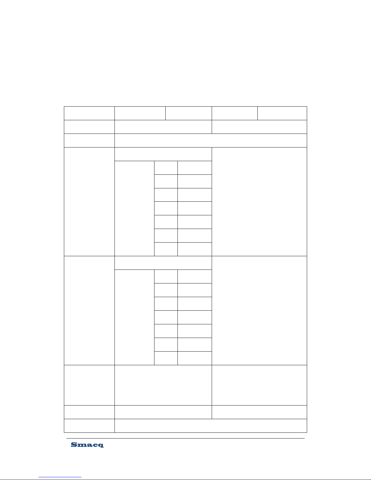
1.3. Product specifications
The following specification parameters, if not specified otherwise, were tested after running the
device for 30 minutes under the temperature of 25 degree Celsius and the relative humidity of
40%.
Diagram 1、Product specifications
Model
PS2016V
PS2016V-485
PS2016I
PS2016I-485
Parameters
Voltage, Temperature(Thermocouple)
Current
Resolution
4½ - Digit
Basic accuracy
±(% reading + digits)
Voltage:0.02%+4
0.05%+4
Temperature
(Thermocouple)
K
±2℃
J
±2℃
R
±3℃
S
±3℃
E
±2℃
T
±2℃
N
±2℃
Range
Voltage:20V,200V
100mA
Temperature
(Thermocouple)
K
-50~1200℃
J
-50~910℃
R
0~1750℃
S
0~1750℃
E
-50~670℃
T
-100~400℃
N
-50~1300℃
Resolution
20V range:1mV
200V range:10mV
Temperature:0.1℃
10uA
Input resistance
1MΩ
20Ω
Sampling rate
2.5Sa/s
5
Channel
16
Channel type
2 line differential input
Channel isolation
>10GΩ
Relay pull time
6ms
Relay release time
4ms
Relay life expectancy
Mechanical 100,000,000 cycles;Electrical 500,000 cycles (full load)
Connection method
Bundled screw terminals
Control method
SCPI instruction
Communication
interface
USB
RS-485
USB
RS-485
PSU(Built-in
self-healing fuse)
USB power
5VDC
USB power
5VDC
Power consumption
5VDC,<150mA
Dimensions
Refer to chapter 2.1 dimensions diagram
Weight
Without screw terminals:500g
With screw terminals:525g
Working
environment
Temperature: 0°C to +50°C
Relative humidity: 5% to 80% (No condensation)
Storage
requirements
Temperature: –20°C to 80°C
Relative humidity: 5% to 90% (No condensation)
Calibration cycle
1 year
2. Product Appearance and Signal Connection
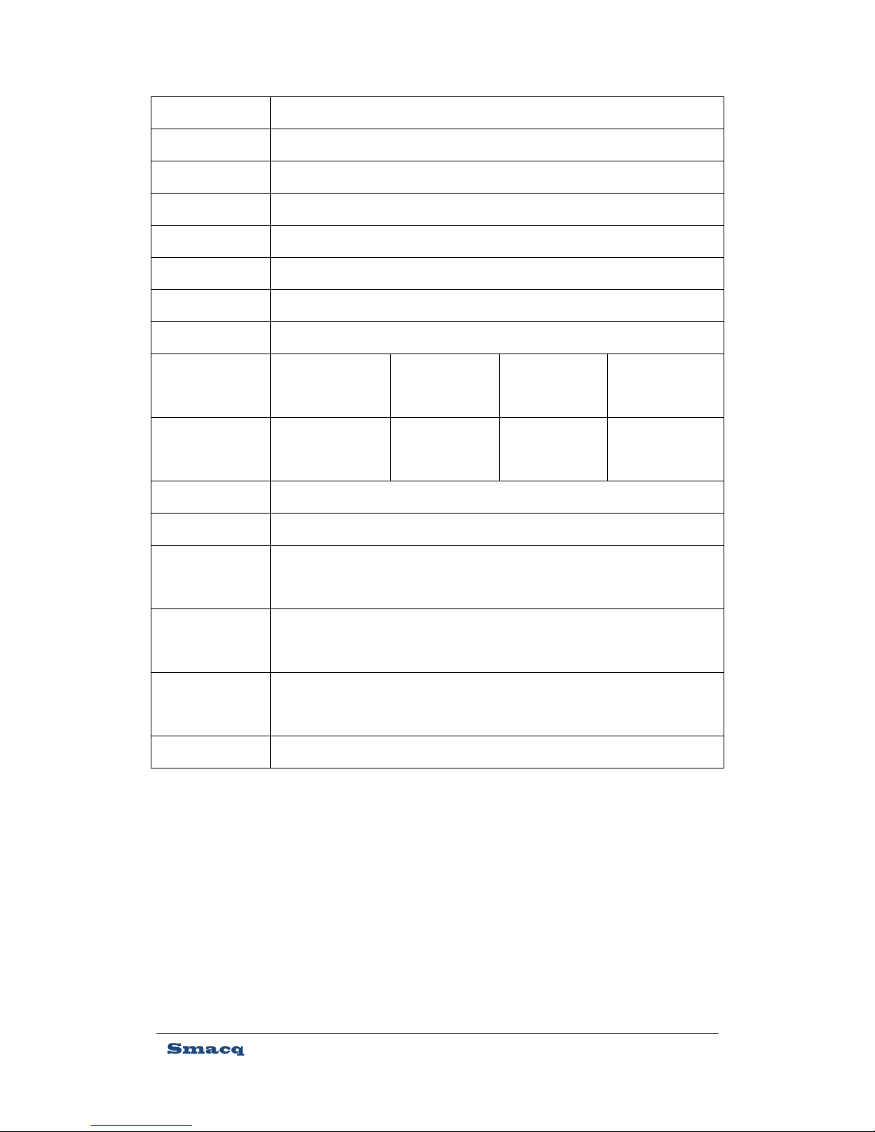
2.1. Product appearance
PS-2000 series DAQ device utilizes metal shield case. It uses plug-in screw terminal connectors to
connect signals. The USB communication interface uses Type-B USB connector. Figure 1 shows its
appearance. The dimensions inside the figure are millimeter.
6
2.2. Signal connection
The screw terminal connector in front of the DAQ device is for connecting the measured
signals.
On the back of the DAQ device, there are two groups of connectors, one USB interface for
connecting with computers directly; the other RS485 interface for connection with computers or
embedded processing system like PLC.
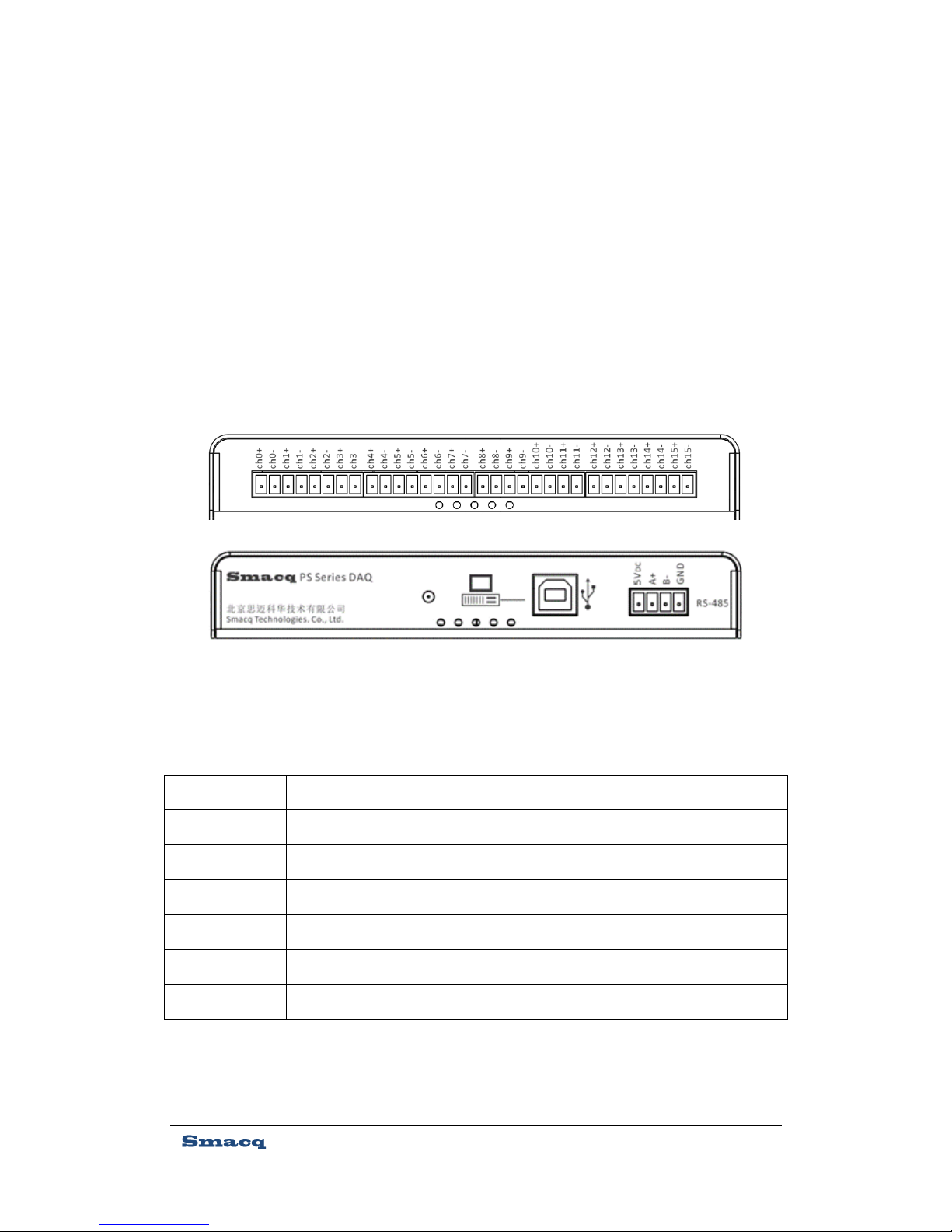
Figure 2 and Diagram 2 show its pin distribution and the corresponding signal in detail.
Diagram 2、Screw terminal connector corresponding signals
Name
Notes
ch+
ch0+ to ch15+ is the signal positive input of channel 0 to 15
ch-
ch0- to ch15- is the signal negative input of channel 0 to 15
5VDC
5VDC power input of RS-485 interface
GND
Power ground of RS-485 interface
A+
Positive input of RS-485 communication signal
B-
Negative input of RS-485 communication signal
Attention:For models with USB interface, there is no need of extra 5VDC power supply.
Figure 2、Screw terminal connector pin detail

7
3. Installation and Testing
3.1. Driver installation
When PS2016 DAQ device is connected to computers running Microsoft Windows for the first
time, it will require installing the driver before the computer can recognize PS2016 correctly.
Open the folder of "\PS Series DAQ/driver" on the Resources CD, double click the file
"SETUP.EXE", then click "Install", and there will be a dialog of success after the driver is installed.
After correctly installing the driver, Windows Device Manager will recognize PS2016 as a virtual
serial port device under the name of "USB-SERIAL CH341A". The OS will assign a serial port
number for the device as shown in parentheses in Figure 3.
Figure 3、The Device Manager with correctly recognized PS2016
8
3.2. Software installation
Open the folder "\PS Series DAQ\PS2016 - DAQ Lite Setup\Volume" and run the file "setup.exe".
Set the installation directory for the software, click "Next" all the way till it's installed. Usually you
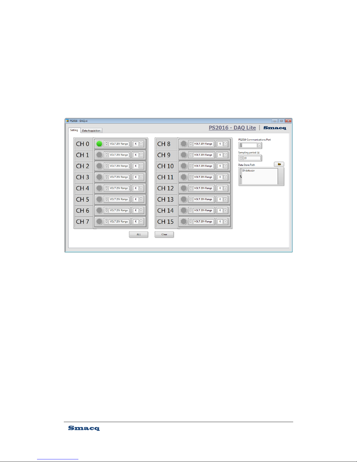
can keep the default installation directory. Start the software after the installation. Figure 4
shows the software interface.
3.3. Voltage signal test
Connect a voltage signal of a known voltage to the PS2016 data collector, as shown in Figure
5.
Figure 4、PS2016-DAQ Lite software interface

9
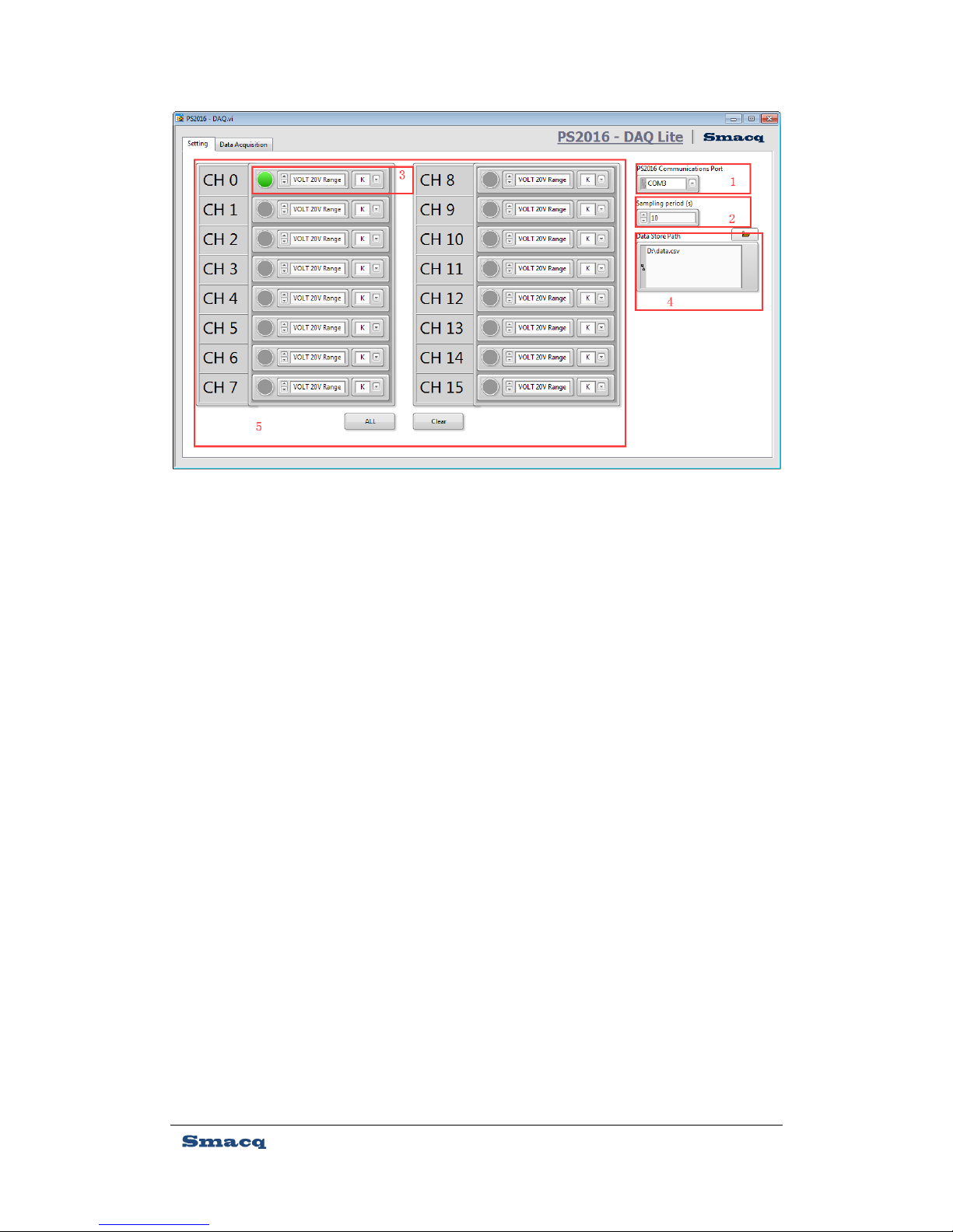
Make corresponding settings on PS2016-DAQ Lite, as shown in Figure 6, with detailed notes
below.
1:Select the correct serial port connection.
2:Set the sampling cycle in seconds.
3:Set the range. Can be set as 20V or 200V range when measuring voltage signals.
4:Set the path of data storage.
5:Choose the channel to run the DAQ device in.
Figure 5、Voltage signal test connection
Attention : When measuring voltage signals, if the thermocouple range is
selected by mistake, the PS2016 DAQ device may be damaged after it runs.
10
Within the data acquisition interface after finishing the settings, click "START" button to
begin the data acquisition and real-time data storage, as showed in Figure 7, with detailed notes
below.
1: Start/Stop button
2: Real time value display.
3: Trend graph display.
4: Corresponding channel legend display.
In the trend graph display, the ordinate scale value is automatically scaled by default. You
can cancel the "automatic Y scale adjustment" by right-clicking the pop-up menu on the ordinate
scale, so as to achieve fixed vertical coordinates. After fixing the ordinate, you can double-click
the ordinate number to modify the ordinate scale value.
The same method can be used to modify the coordinate scale value.
Figure 6、Voltage testing settings

11
3.4. Temperature signal test
When using PS2016 DAQ device to measure temperature, the thermocouple needs to be
connected to the signal as shown in Figure 8 below.
When using K type thermocouple, the maximum measuring range is 1100℃.
When using other types of thermocouples, the maximum measuring range is the temperature
range corresponding to 45.108mV on its indexing table.
Figure 7、Voltage test acquisition interface
The thermocouple probe must be insulated during the connection. The exposed metal
on the thermocouple probe cannot be connected directly to any voltage signal.
Otherwise, the PS2016 DAQ device may be damaged.

12
You will need to set the range as "thermocouple" in settings, and choose the thermocouple
type you use, as shown in Figure 9, with detailed notes below:
1:Choose correct serial port number
2:Set sampling cycle, measured in seconds.
3:Set range. Choose thermocouple range when measuring temperature and choose
corresponding thermocouple type.
4:Set data storage path.
5:Choose the channel to acquire.
Figure 8、Thermocouple signal test connection

13
Within the data acquisition interface after finishing the settings, click "START" button to
begin the data acquisition and real-time data storage, as showed in Figure 10, with detailed notes
below.
1: Start/Stop button
2: Real time value display.
3: Trend graph display.
4: Corresponding channel legend display.
In the trend graph display, the ordinate scale value is automatically scaled by default. You
can cancel the "automatic Y scale adjustment" by right-clicking the pop-up menu on the ordinate
scale, so as to achieve fixed vertical coordinates. After fixing the ordinate, you can double-click
the ordinate number to modify the ordinate scale value.
The same method can be used to modify the coordinate scale value.
Figure 9、Temperature test setting

14
3.5. Data file detail
All data files are saved in .csv format, readable by Microsoft Excel, as shown in Figure 11 below.
The data file consists of beginning time, cycle, measuring type and all original data for this
acquisition.
Figure 10、Temperature test acquisition interface
Figure 11、Data file

15
4. Programming Guide
4.1. Overview
When you need to embed PS2016 into your own measuring and control system, you can
control PS2016 via the SCPI instructions detailed in this chapter.
USB interface
The USB interface on PS2016 DAQ device is virtual serial port. It has a default baud of 9600,
8 bit data bits, 1 stop bit, no hardware handshake and its command uses linefeed "\n" as the end
character, i.e. 0x0A.
RS-485 interface
If your PS2016 DAQ device is equipped with RS-485 interface, it has a default baud of 9600,
8 bit data bits, 1 stop bit, no hardware handshake and its command starts from 1-byte address,
with linefeed "\n" as the end character, i.e. 0x0A. When the address byte is set to 0x00, it
represents the broadcast.
4.2. General commands
*IDN?
Get device information.
*RST
Reset device default settings. This command will disconnect all channels but will not
change the baud setting.
4.3. Setting commands
BPS:9600
Setting serial communication baud as 9600.
BPS:115200
Setting serial communication baud as 9600.
RNG:[n]

16
Set DAQ device range. N can be set as 2, 3, or 9。
When set as 2, it represents the range of 20V; when set as 3, it represents the range of
200V; when set as 9, it represents measuring thermocouple.
ADDR:[n]
Set the address of RS-485 interface. This command is only for models with RS-485
interface. During the setting, there can be only one PS2016 connected to RS-485 bus. Then
the device sends a broadcast address to set its address.
4.4. Measurement commands
CH[n]:V?
Read measured voltage from specified channel with return value measured in V. The value
of n ranges from 0 to 15, corresponding to channel 0 to channel 15.
For example:USB send CH0:V?\n
USB answer 0.01000\n
RS-485 send \00 CH0:V?\n
RS-485 answer \00 0.01000\n
CH[n]:T[TYPE]?
Read measured temperature from specified channel with return value measured in ℃. The
value of n ranges from 0 to 15, corresponding to channel 0 to channel 15.
TYPE can be set as K, J, R, S, B, E, T or N, corresponding to respective type of thermocouple.
For example:USB send CH0:TK?\n
USB answer 25.5678\n
RS-485 send \00 CH0:TK?\n
RS-485 answer \00 25.5678\n

17
5. Ordering information
Device
Model
Notes
PS2016V
16 channel differential voltage input, Thermocouple measurement with cold
end compensation, USB interface
PS2016I
16 channel current input, USB interface
PS2016V-485
16 channel differential voltage input, Thermocouple measurement with cold
end compensation, RS485 interface
PS2016I-485
16 channel current input, RS485 interface
Optional accessories
Model
Notes
USB-A-B
USB connector,1.5 meters,USB-A type to USB-B type
TB8-3.81
Screw terminal connector,8 digits,with spacing of 3.81mm
Optional accessories
Model
Notes
SDIN
35mmDIN guide mounting bracket
STHK-1.5
K type thermocouple,1.5 meters
STHK-3
K type thermocouple,3 meters
STHK-5
K type thermocouple,5 meters

18
6. Service and Warranty
All Smacq products can be serviced free of charge under normal use within their warranty. Refer
to the warranty notes inside their package for details.
Unless otherwise provided in this manual or warranty statement, Smacq does not provide any
other warranties, either express or implied.
If you need technical support or more service details, or if you have any questions using this
product or reading this document, feel free to contact us.
Tel:010-52482802
Email:service@smacq.com
Website:www.smacq.com / www.smacq.cn
19
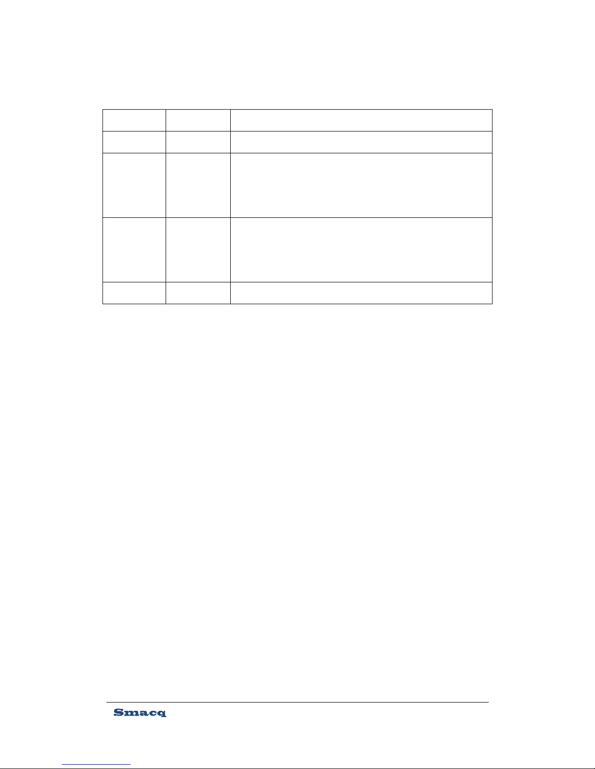
7. Revision history
Date
Version
Notes
2016.8.30
Rev: A
Initial release
2016.11.14
Rev: B
1、 Added independent range setting for every channel in
software PS2016-DAQ Lite.
2、 K-type thermocouple supports measuring up to 1100℃.
2017.3.30
Rev: C
Change RS-485 connector pin detail to correspond to the
changes in products with RS-485 interface manufactured after
April 2017.
2017.4.20
Rev: D
Update the accuracy of thermocouples measurements.
 Loading...