

Page 1
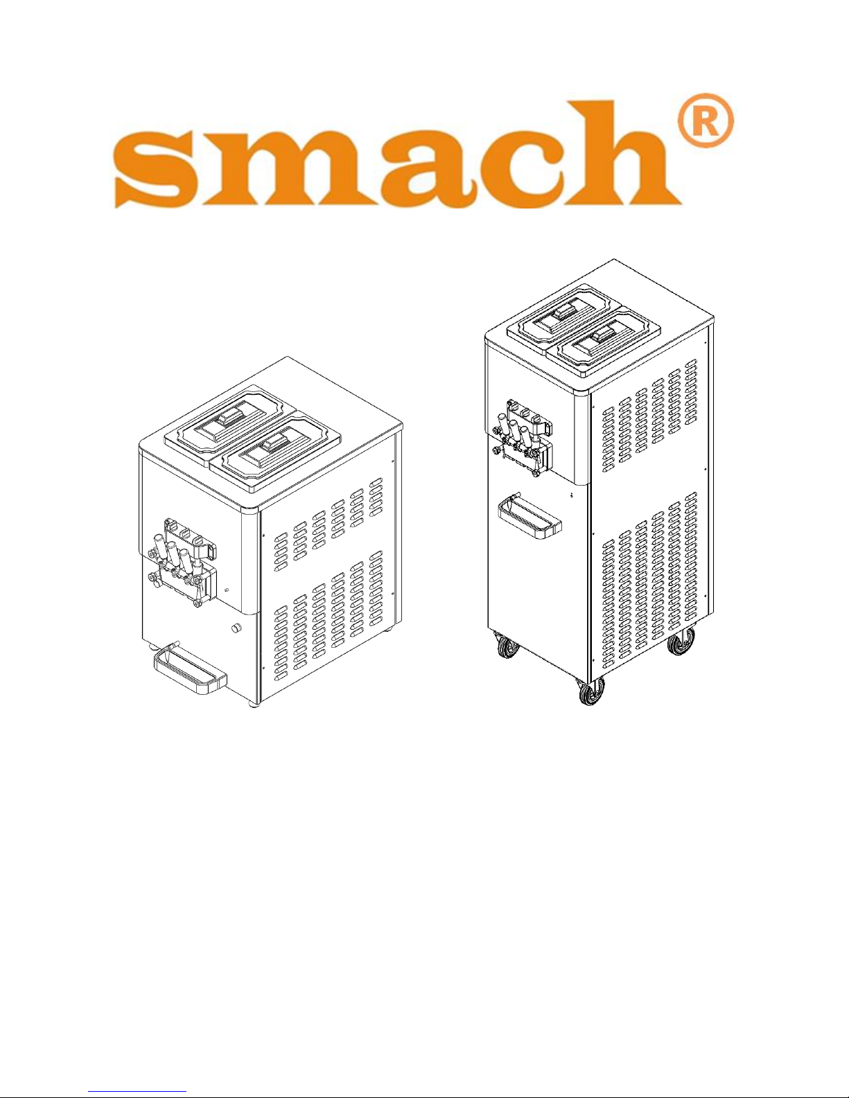
EFE 2500A/AF EFE 4000A/AS/AN
SOFT-SERVE AND FROZEN YOGHURT FREEZER
USER GUIDE
(OPERATING MANUAL)
for
MODEL: EFE 2500A/AF - 4000A/AS/AN
Manual Number: V 004 – 23.07.2014
Page 2

1
EFE 2500A /AF - 4000A/AS/AN
1.TABLE OF CONTENTS
1.TABLE OF CONTENTS ..................................................................................................................... 1
2.CONGRATULATIONS AND THANK YOU! ........................................................................................ 3
3.SYMBOLS IN MANUAL ................................................................................................................... 4
4.CONTACT DETAILS & HELP DESK .................................................................................................... 5
5.ELECTRICAL CONNECTION NOTICE ................................................................................................ 6
6. WARNINGS & SAFETY ................................................................................................................... 7
7. PARTS IDENTIFICATION ................................................................................................................ 9
7.1 Exploded View of Machine .................................................................................................... 9
7.1.1. EFE 2500 A/AF ................................................................................................................ 9
7.1.2 EFE 4000 A/AS ............................................................................................................... 11
7.1.3 EFE 4000 AN .................................................................................................................. 13
7.2 Exploded View of Dispensing Head ...................................................................................... 15
7.3 Exploded View of Self Service Unit ...................................................................................... 16
7.4 Exploded View of Air Tube ................................................................................................... 17
7.5 Exploded View of Liquid Level Sensor .................................................................................. 18
8. MACHINES WITH AIR-COOLED CONDENSER .............................................................................. 19
9. MACHINES WITH WATER-COOLED CONDENSER ........................................................................ 20
10. CONTROL DIAL .......................................................................................................................... 21
11. OPERATING PROCEDURE .......................................................................................................... 22
12. PREPARATION AND START UP PROCEDURE ............................................................................. 22
12.1 PREPARATION .................................................................................................................... 22
12.2 STARTING THE MACHINE ................................................................................................... 23
12.3 DISPENSING ICE CREAM ..................................................................................................... 24
13. STEP-BY-STEP CLEANING - SANITIZING PROCEDURE ................................................................ 24
13.1 CLEANING PROCEDURE ...................................................................................................... 25
13.2 BRUSH CLEANING PROCEDURE .......................................................................................... 27
13.3 SANITIZING PROCEDURE .................................................................................................... 29
14. STEP-BY-STEP ASSEMBLY PROCEDURE ..................................................................................... 30
14.1 DISPENSING HEAD ASSEMBLY ............................................................................................ 30
14.1.1 Dispensing Head O-Ring Assembly: ............................................................................ 30
14.1.2 Dispensing Head Piston – O-Ring Assembly: .............................................................. 30
14.1.3 Dispensing Head Piston Assembly: ............................................................................. 31
14.1.4 Dispensing Head Piston Lifter Assembly: .................................................................... 32
14.1.5 Dispensing Head Lifter Rod Assembly: ....................................................................... 33
14.1.6 Dispensing Head Assembled ....................................................................................... 33
14.2 BEATER ASSEMBLY ............................................................................................................. 34
14.2.1 Seal Assembly:............................................................................................................. 34
14.2.2 Inserting the Beater into the Barrel ............................................................................ 34
Page 3

2
EFE 2500A /AF - 4000A/AS/AN
14.3 FITTING THE ASSEMBLED DISPENSING HEAD .................................................................... 35
14.3.1 Placing the Dispense Head: ......................................................................................... 35
14.3.2 Tightening the Screws: ................................................................................................ 35
14.4 ASSEMBLY OF THE AERATION TUBE .................................................................................. 36
14.5 ASSEMBLY OF HOPPER AGITATOR TO THE MACHINE ....................................................... 38
14.6 LIQUID LEVEL SENSOR ASSEMBLY ...................................................................................... 40
14.7 HOPPER COVER ASSEMBLY ................................................................................................ 41
15. POSSIBLE FAILURES AND SOLUTIONS ....................................................................................... 41
16. ELECTRICAL CIRCUIT DIAGRAMS .............................................................................................. 43
16.1 EFE 2500A ........................................................................................................................... 43
16.2 EFE 4000A/AS ..................................................................................................................... 47
WARRANTY DOCUMENT AND CONDITIONS ................................................................................... 51
Page 4
3
EFE 2500A /AF - 4000A/AS/AN
2.CONGRATULATIONS AND THANK YOU!
Congratulations and thank you for acquiring a Soft-Serve Ice Cream Machine
manufactured especially in Turkey by Smach® Gıda Makine A.Ş.
If you encounter a problem with the Smach® Soft Serve Ice Cream Machine, please
contact your local service technician.
Please familiarize yourself with the machine by taking some time to study this manual. If
you get to know this little ice-cream factory, it has the potential of making good profit.
Notice and no warrantee: These pages are provided as a service and informational
purpose only, and on the assumption that the recipient of the Soft-Serve Freezer and the
operator of the Soft-Serve Freezer is competent to perform the required tasks, including,
but not limited to operation and/or repair of power equipment, for which the information is
provided, and that person is knowledgeable and mindful of proper safety precautions.
Neither Smach®, nor any of their respective employees make any claims about the
suitability or fitness of the information contained herein which is provided strictly on an "asis" basis, without any express or implied warranty, guarantee, assurance of quality,
conformity of specifications, reliability, functionality, or suitability. In no event shall
SMACH® and/or its employees be held liable, whether in contract or tort, to any party for
any direct, indirect, punitive, or consequential damages, including, but not limited to lost
profits and business interruption, arising out of any errors, typographical or otherwise,
inaccuracies, omissions, or delays arising out of or pertaining to the use, reliance on, or
inability to use any type of information, part, or good, even if notified in advance about the
possibility of such action. Information in this manual is subject to change without notice. All
rights reserved.
BEFORE USING THE MACHINE READ CAREFULLY THIS
MANUAL. PAY ATTENTION TO THE SAFETY INSTRUCTIONS.
Page 5
4
EFE 2500A /AF - 4000A/AS/AN
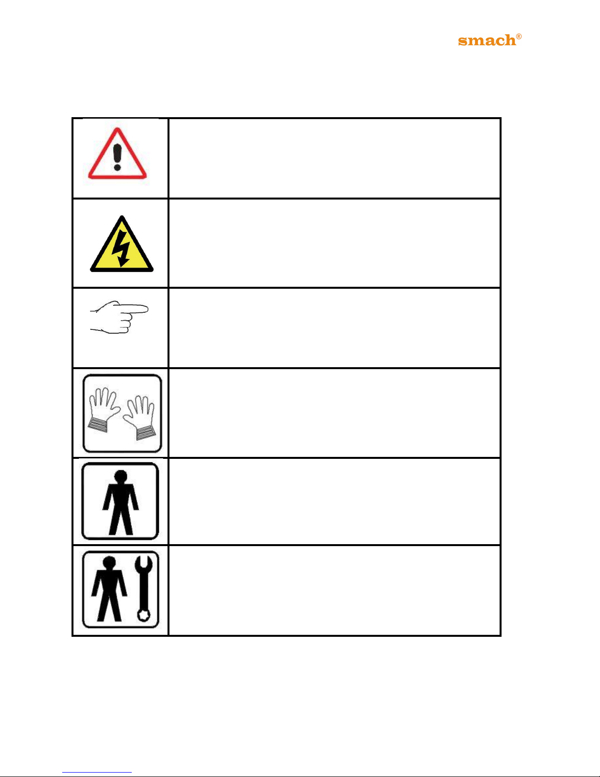
3.SYMBOLS IN MANUAL
WARNING
When you see this symbol on your freezer or in this manual, be
alert to the potential for personal injury. Follow recommended
precautions and safe operating practices.
ELECTRIC DANGER
This symbol indicates the presence of electric shock hazards.
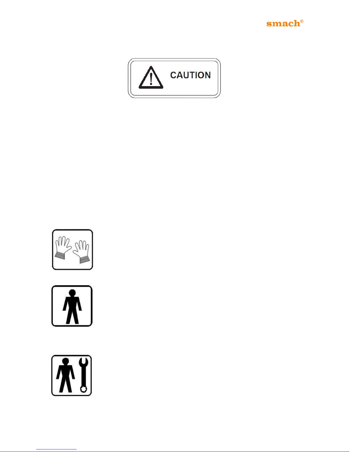
NOTE
It points out significant information for the stuff involved.
PROTECTIONS
This symbol means that operator must use protection against an
implicit risk of accident.
MACHINE OPERATOR
He/She is the person who has no specific expertise and she/he
will operate the freezer.
MAINTENANCE ENGINEER
He/She is a skilled engineer for the operation of the machine
under normal conditions; he/she is able to carry out interventions
on mechanical parts and all adjustments, as well as maintenance
and repairs. He/She is qualified for interventions on electrical and
refrigeration components.
Page 6
5
EFE 2500A /AF - 4000A/AS/AN
4.CONTACT DETAILS & HELP DESK
Smach® Gıda Makine San.Tic.A.Ş
ADDRESS AND CONTACT DETAILS
Smach® Gıda Makine San.Tic.A.Ş
Guzelyurt Mah.5762 Sok.No 5/A
Orta Olcekli San.Bol.
Manisa/TURKEY
Tel: +90 236 233 39 29
Fax: +90 236 236 12 59
E-Mail: [email protected]
When calling Smach® have the following information ready:
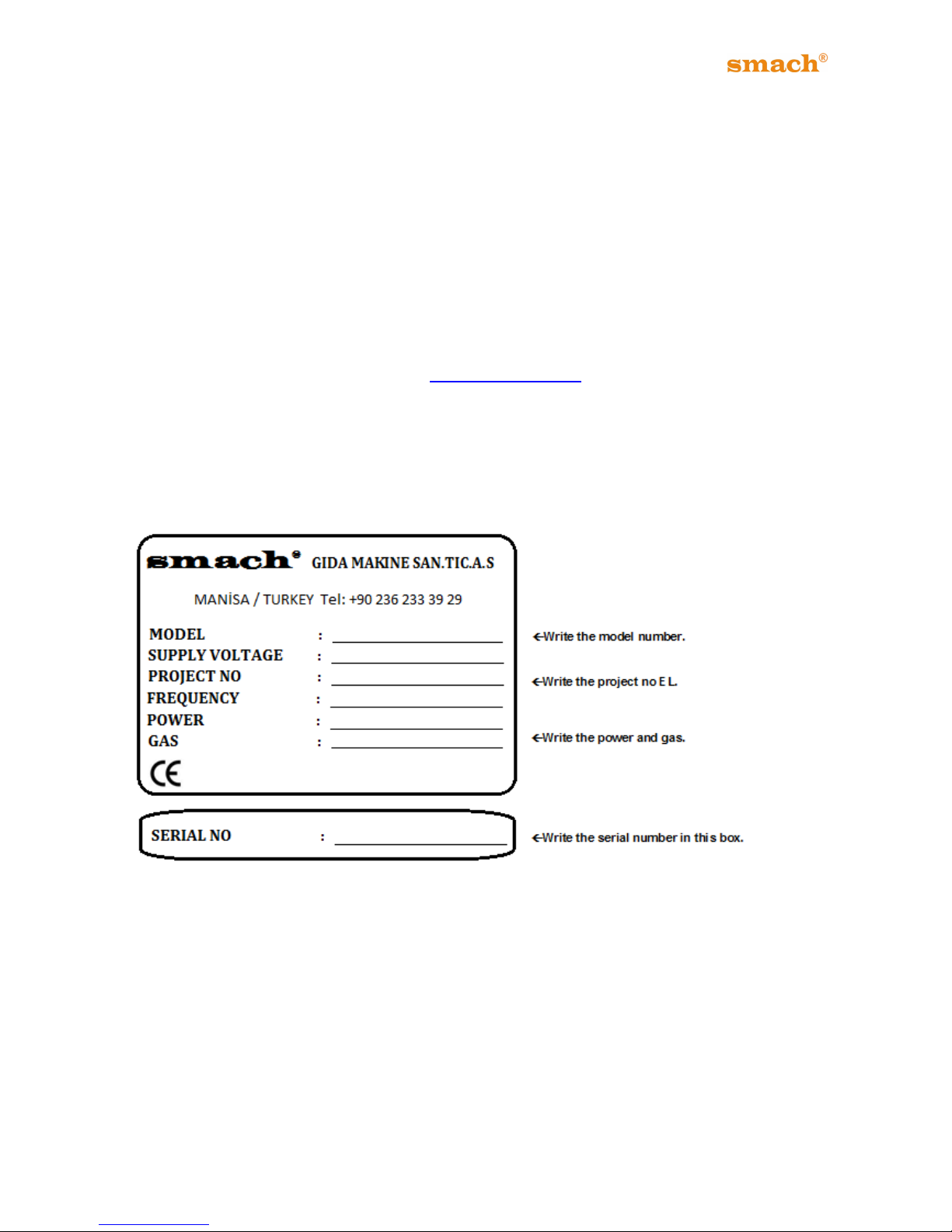
1. Freezer Serial Number: Found on body panel
2. A brief description of the problem
Page 7
6
EFE 2500A /AF - 4000A/AS/AN
5.ELECTRICAL CONNECTION NOTICE
1. Please make sure that the power supply conforms to the electrical data label (Rating
Plate).
2. Check the data label (Rating Plate) for the required circuit breaker amperage. Only plug
into an electrical wall socket that complies with the required amperage of the machine.
3. Machine should be installed according to the local authority electrical code/regulations it
is used in, as well as to other work health and safety requirements. If you are not sure,
please contact your local authority for details.
4. This symbol indicates the presence of electric shock hazards. Inside the
enclosures of the machine there are electrical shock hazards, therefore,
DO NOT remove any panels if you are not a qualified technician of an
authorized service provider.
5. WARNING: To avoid risk of injury from electric shock, if you are not a
qualified and duly authorized service technician, do not open the enclosure
panels on the sides and back of the machine.
6. The power supply must be properly grounded to prevent electrical shock. Check with a
qualified installer for compliance.
7. The fuse must be 220-240V, 50 Hz 16 Amp / 24 Amp or 380-400V, 50 Hz 32 Amp
(Before plug the machine, see metallised label on the back of the machine.)
Page 8
7
EFE 2500A /AF - 4000A/AS/AN
6. WARNINGS & SAFETY
Read and understand all safety messages in this manual. Read and understand the safety
decals on your freezer. Take notice of the location of all decals on the freezer and keep
the safety decals in good condition. Check them periodically and replace missing,
damaged or illegible safety decals. The safety decals must remain in place and legible for
the life of the freezer.
Keep your Freezer clean and tidy. When it needs repairing, work with an authorized
SMACH® service agent.
Smach® is concerned about the safety of the person/s using the machine. Therefore
please take note and abide by amongst others, the following WARNINGS:
The weight of the machine is no less than 170 kg for EFE 2500A
and 230 kg for EFE 4000A. The person who carries the machine
must be careful while moving the freezer.
Always follow local authority food safety and other health codes.
Do NOT touch barrel feeder hole during cleaning.
Always follow in-store operating and food hygiene safety and other
health code
Do not clean the machine with high-pressure water.
Use potable water to clean the parts.
Do NOT use the machine before studying this User Guide. Failure to
follow this instruction may result in equipment damage, poor
performance, health hazards or personal injury.
Only use food-grade lubricant when changing or replacing the O-
rings on the pistons.
A potential risk exists if the User Guide instructions and other safety
precautions are not strictly followed.
Do NOT allow anyone to attempt any repairs to the machine, unless
the main power supply to it has been disconnected from the power
supply point.
Never open the panels to reach inside the Freezer body. (Only by
authorized technicians)
Technical maintenance must be done by authorized technicians.
Page 9

8
EFE 2500A /AF - 4000A/AS/AN
Do NOT allow untrained personnel to operate the Soft-Serve
Freezer.
Do NOT insert or remove the beater from the freezing barrel while
the Machine is connected to the power supply. First isolate the power
supply.
Do NOT remove the hopper cover (lid) unless you are filling or re-
filling the hopper with the mix.
Do NOT switch ON the Machine at the wall socket switch when the
following has not yet been done: (a) the beater is inserted properly
(b) the barrel head is fitted correctly and the four nuts screwed on
correctly and tightly, and (c) the barrel is flooded with Mix.
When removing, replacing or cleaning the removable parts do so with
caution because the beater blades have sharp edges that can easily
cause injury.
WINTER STORAGE
If the place of business is to be closed and the machine won’t run during
the winter months, it’s important to protect the freezer.
Disconnect the freezer from the main power source to prevent possible
electrical damage.
For WATER-COOLED freezers, disconnect the water supply. Use the air
pressure on the outlet side to blow out any water remaining in the condenser. This is
extremely important. Failure to follow this procedure may cause severe and costly damage
to the refrigeration system.
NOTICE: Smach® Gıda Makine A.Ş will not take any responsibility if the users do not follow
all the instructions as described in this User Guide.
Page 10
9
EFE 2500A /AF - 4000A/AS/AN
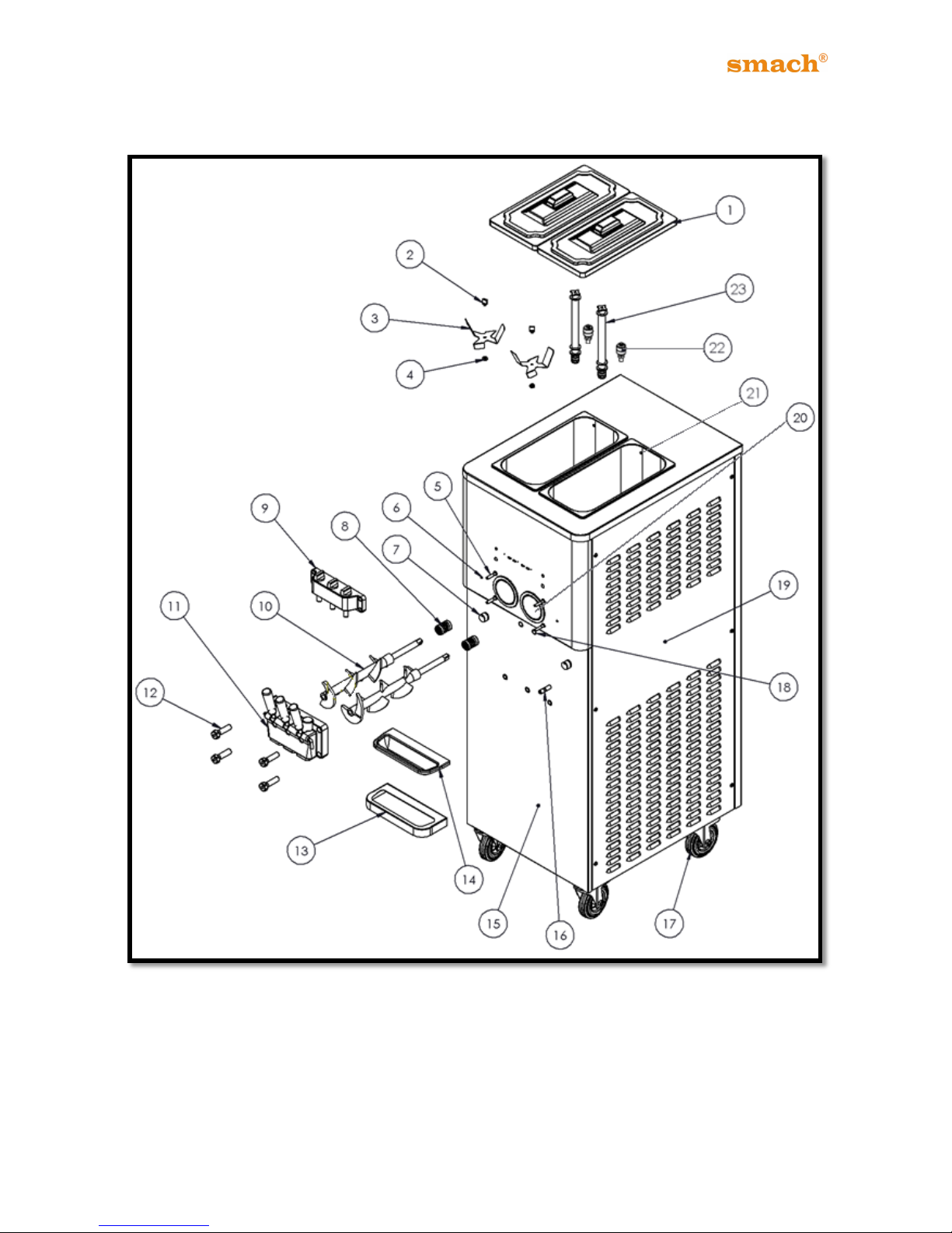
7. PARTS IDENTIFICATION
7.1 Exploded View of Machine
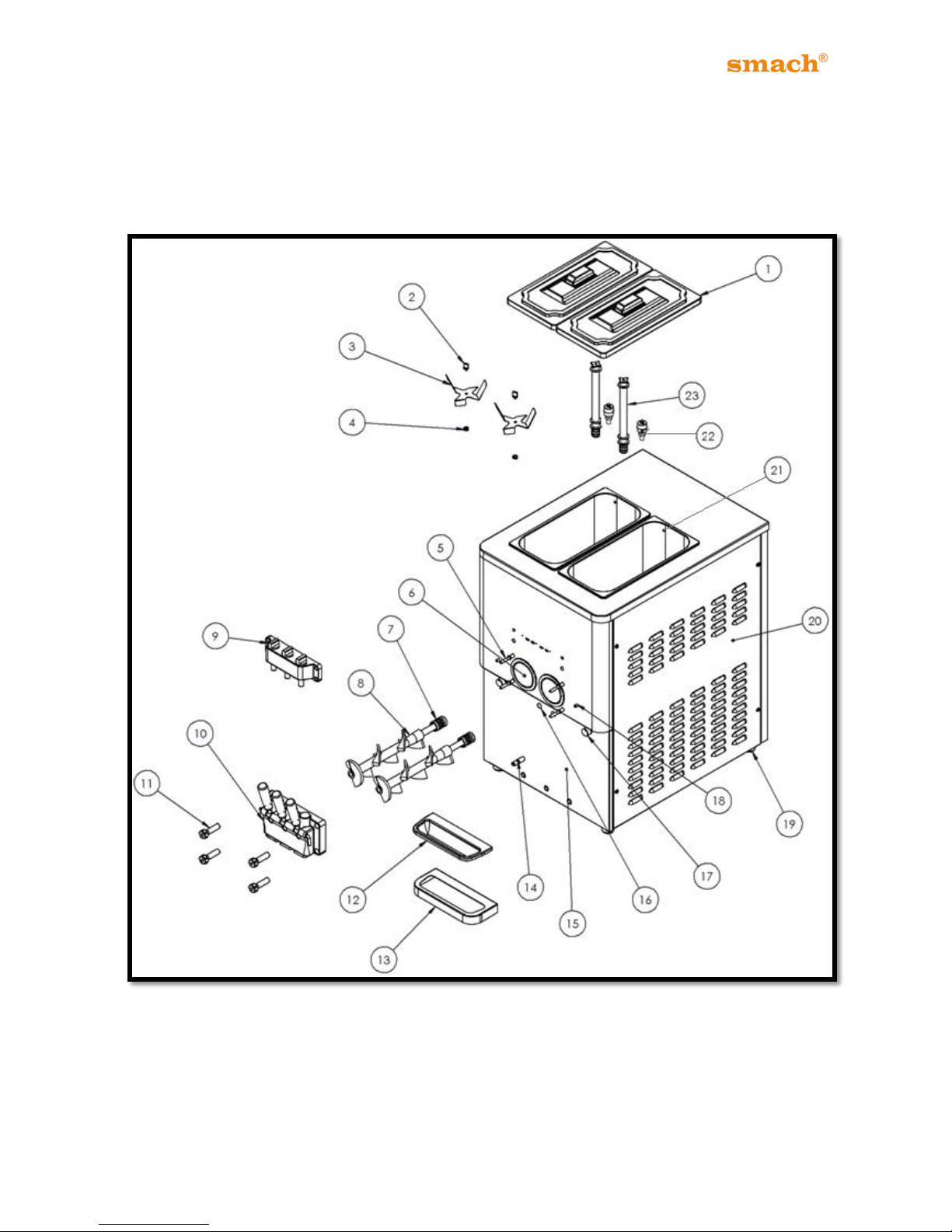
7.1.1. EFE 2500 A/AF
Figure 1
The only difference between 2500A and AF is the rotation speed of beater.
Page 11
10
EFE 2500A /AF - 4000A/AS/AN
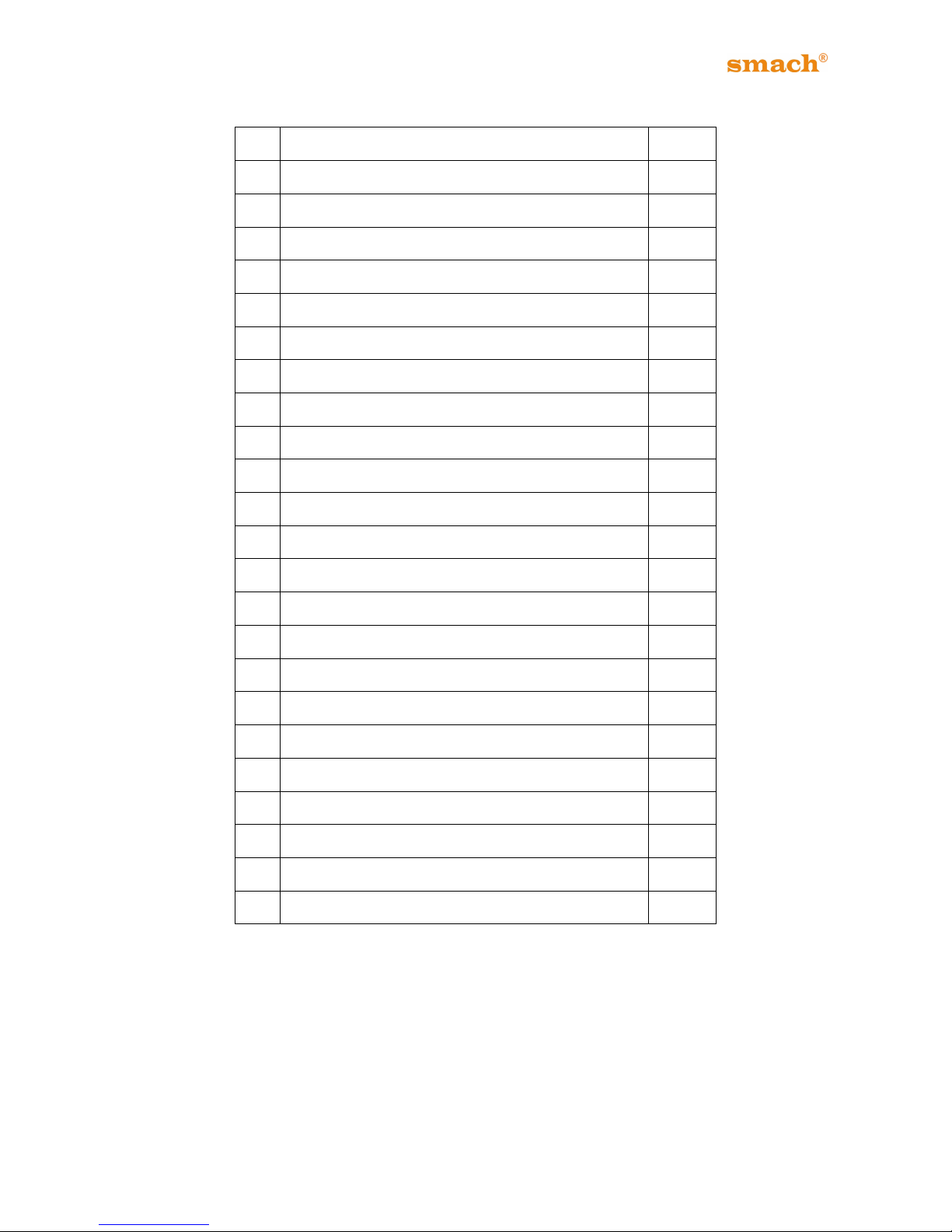
NO
PART NAME
QUA.
1
Hopper Cover
2
2
Hopper Agitator Screw
2
3
Hopper Agitator
2
4
Hopper Agitator Seal
2
5
Stud
4
6
Barrel
2
7
Beater Seal
2
8
Beater
2
9
*Self Service Unit
1
10
Head Group
1
11
Head Screws
4
12
Drip Tray
1
13
Drip Tray Holder
1
14
Drain
1
15
Front Panel
1
16
Photo Sensor
1
17
Selector Switch
2
18
LED
2
19
Base
4
20
Side Panel (Right)
1
21
Hopper
2
22
Liquid Level Sensor
2
23
Air Tube
2
Table 1
(*) Parts marked with this symbol are optional.
Page 12
11
EFE 2500A /AF - 4000A/AS/AN
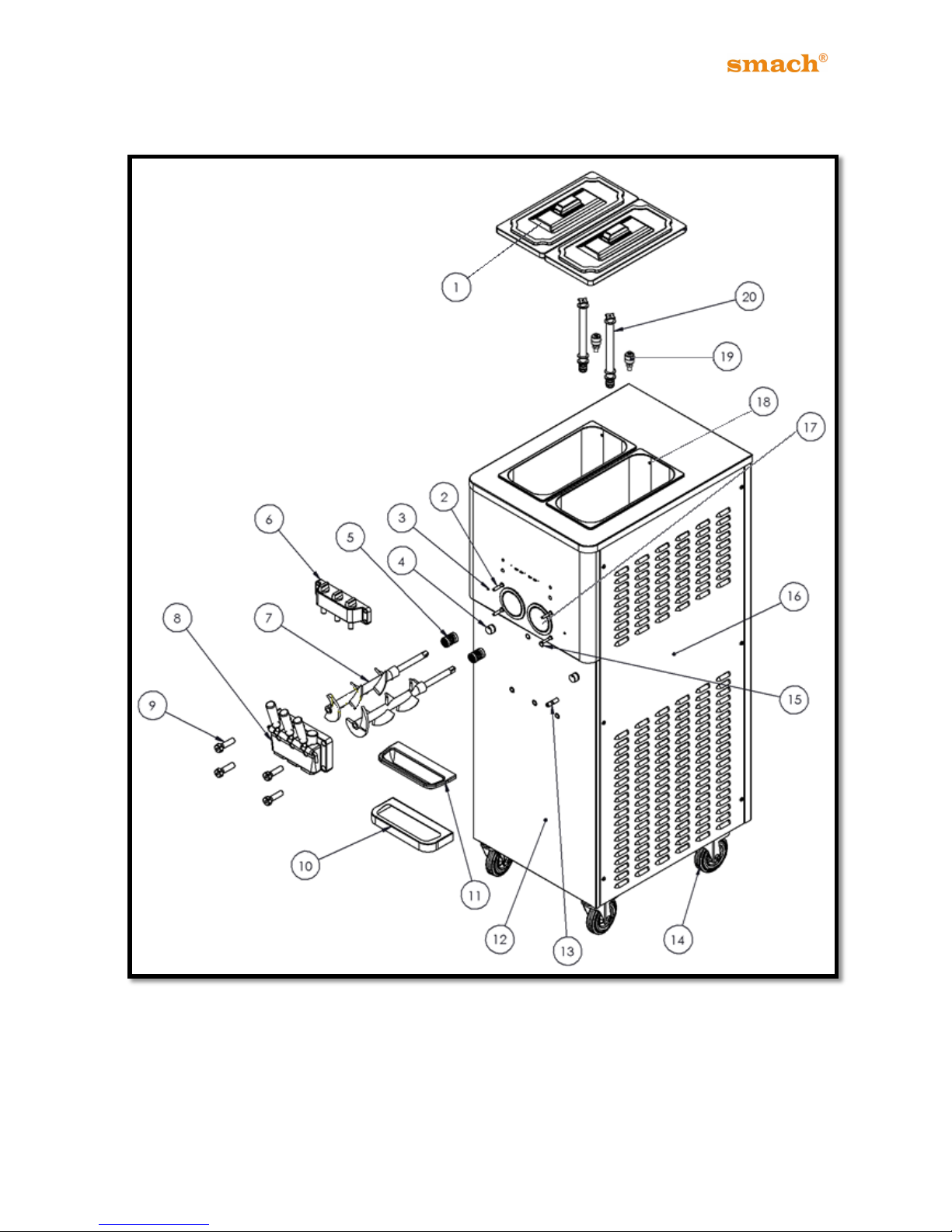
7.1.2 EFE 4000 A/AS
Figure 2
Page 13
12
EFE 2500A /AF - 4000A/AS/AN
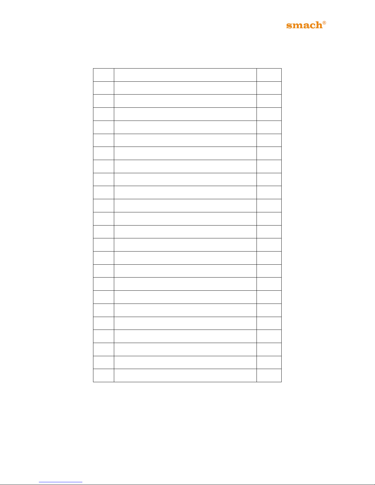
NO
PART NAME
QUA.
1
Hopper Cover
2
2
Hopper Agitator Screw
2
3
Hopper Agitator
2
4
Hopper Agitator Seal
2
5
Stud 4 6
LED 2 7
Selector Switch
2
8
Beater Seal
2
9
*Self Service Unit
1
10
Beater
2
11
Head Group
1
12
Head Screws
4
13
Drip Tray Holder
1
14
Drip Tray
1
15
Front Panel
1
16
Drain
1
17
Wheel
4
18
Photo Sensor
2
19
Side Panel (Right)
1
20
Barrel
2
21
Hopper
2
22
Liquid Level Sensor
2
23
Air Tube
2
Table 2
(*) Parts marked with this symbol are optional.
Page 14
13
EFE 2500A /AF - 4000A/AS/AN
7.1.3 EFE 4000 AN
Figure 3
Page 15
14
EFE 2500A /AF - 4000A/AS/AN
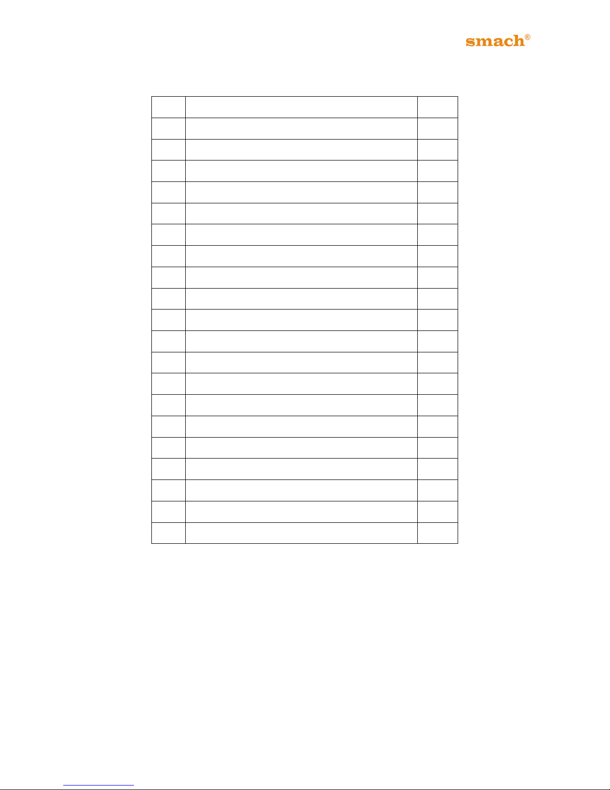
NO
PART NAME
QUA.
1
Hopper Cover
2
2
Stud 2 3
LED 2 4
Selector Switch
2
5
Beater Seal
4
6
*Self Service Unit
2
7
Beater
2
8
Head Group
2
9
Head Screws
1
10
Drip Tray Holder
2
11
Drip Tray
1
12
Front Panel
4
13
Drain
1
14
Wheel
1
15
Photo Sensor
1
16
Side Panel (Right)
1
17
Barrel
4
18
Hopper
2
19
Liquid Level Sensor
1
20
Air Tube
2
Table 3
Page 16
15
EFE 2500A /AF - 4000A/AS/AN
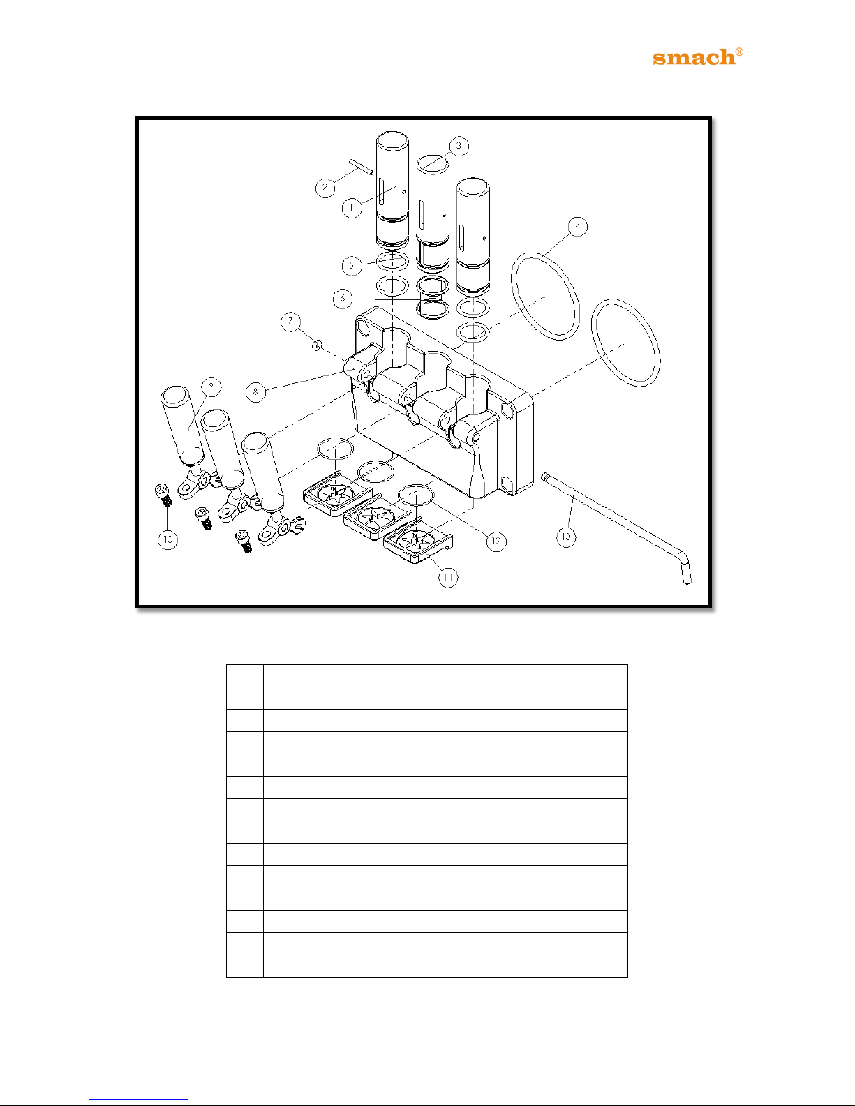
7.2 Exploded View of Dispensing Head
Figure 4
NO
PART NAME
QUA.
1
Piston
2
2
Piston Pin
3
3
Middle Piston
1
4
O-Ring 89,69 x 5,33
2
5
O-Ring 27,2 x 3,53
4
6
Middle Piston O-Ring
1
7
4,8 x 3,53 O-Ring NBR
1
8
Dispensing Head
1
9
Piston Lifter
3
10
Speed Adjuster
3
11
Nozzle
3
12
O-Ring 34,65 x 1,78
3
13
Lifter Rod
1
Table 4
Page 17
16
EFE 2500A /AF - 4000A/AS/AN
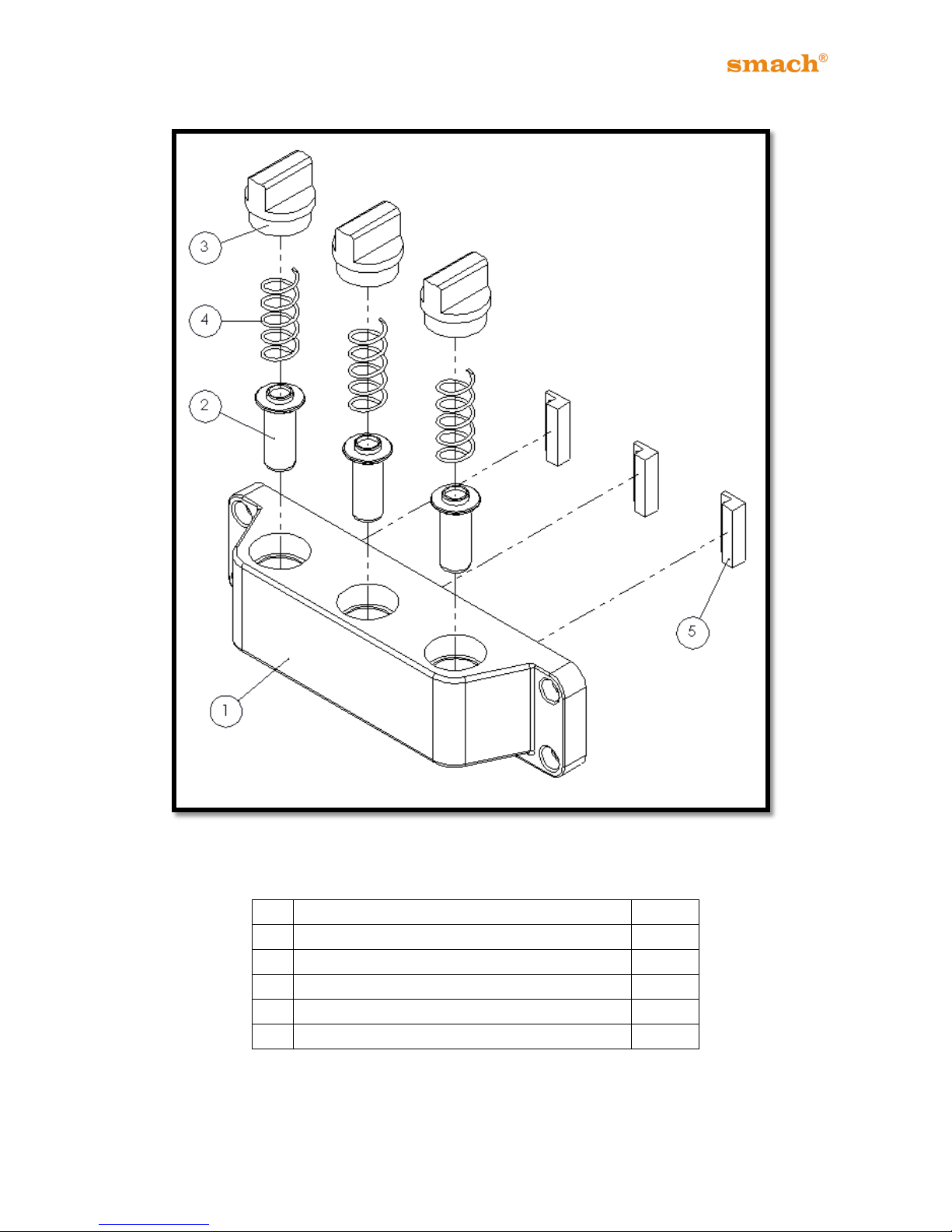
7.3 Exploded View of Self Service Unit
Figure 5
NO
PART NAME
QUA. 1 Self Service Mounting Unit
1 2 Self Service Spring Pressure Pin
3 3 Self Service Screw M30
3
4
Self Service Spring
3 5 Rectangular Reed Sensor
3
Table 5
Page 18
17
EFE 2500A /AF - 4000A/AS/AN
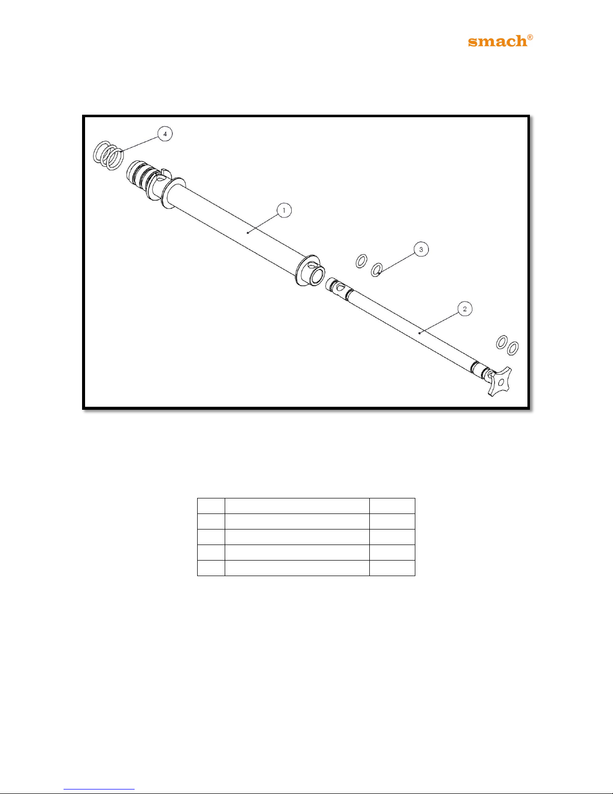
7.4 Exploded View of Air Tube
Figure 6
NO
PART NAME
QUA.
1
Outer Air Tube_L
1
2
Inner Air Tube_L
1 3 8 x 2,50 O-Ring
4 4 18,70 x 2,62 O-Ring
3
Table 6
Page 19
18
EFE 2500A /AF - 4000A/AS/AN
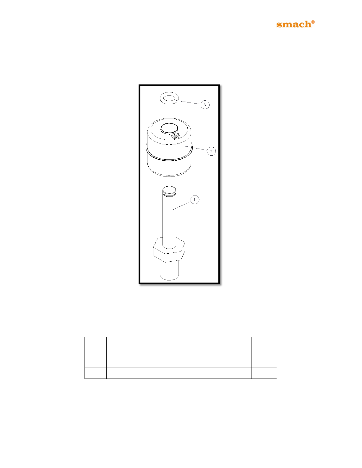
7.5 Exploded View of Liquid Level Sensor
Figure 7
NO
PART NAME
QUA.
1
PLS_045 Liquid Level Sensor Body
1
2
PLS Liquid Level Sensor Float
1
3
4,8 x 3,53 mm O-Ring Silicon Yellow
1
Table 7
Page 20
19
EFE 2500A /AF - 4000A/AS/AN
8. MACHINES WITH AIR-COOLED CONDENSER
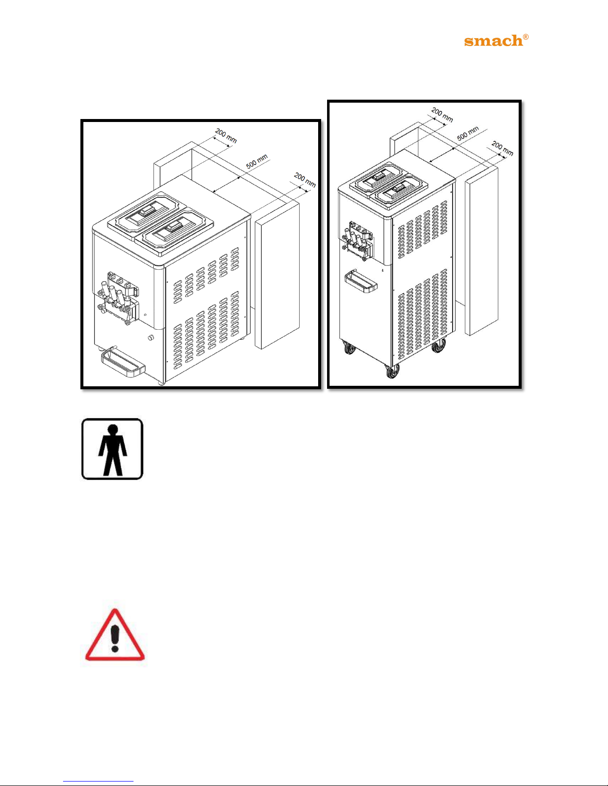
Figure 8 Figure 9
The freezer requires a minimum of 200 mm of clearance on both sides and
500 mm in the rear of the unit. (Figure 8-9)
The clearance will allow sufficient amount of air flow across the condenser. Failure to allow
adequate clearance can reduce the refrigeration capacity of the freezers and cause
permanent damage to the compressors.
Position the machine for easy accessibility for cleaning, servicing and maintenance. A
clean environment is also essential for the proper performance of the freezer.
Attention: The freezer must not be exposed to direct sunlight. If it
stands in direct sunlight the performance will decrease. As the air
temperature increases the performance decreases. This is true for all
refrigeration equipment.
Page 21
20
EFE 2500A /AF - 4000A/AS/AN
9. MACHINES WITH WATER-COOLED CONDENSER
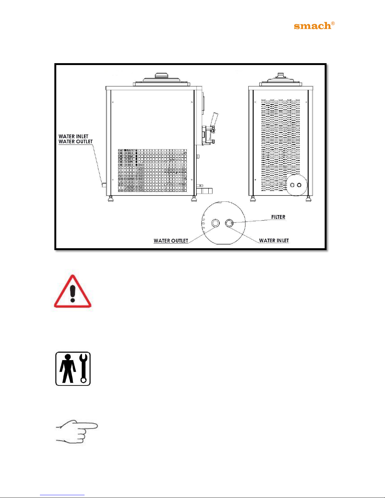
Figure 10
Water-cooled machine must be connected to running water supply, or a
cooling tower. Water must have a pressure between 1-10 bar and a
delivery at least equal to the estimated hourly consumption.
Connect inlet pipe marked by plate “Water Inlet” to water supply installing a shut-off valve,
and outlet pipe marked by plate “Water Outlet” to a drain pipe, installing a shut-off valve.
If water valve is retarded, this operation will have to be carried out by skilled
personnel. Valve adjustment must be carried out in such a way that no
water flows when machine is off and lukewarm water flows when machine
is on.
Water consumption increases if temperature of entering water is above 20°C.
The filter should be cleaned every 3 months.
The use of potable water in the cooling system is recommended.
Page 22
21
EFE 2500A /AF - 4000A/AS/AN
10. CONTROL DIAL
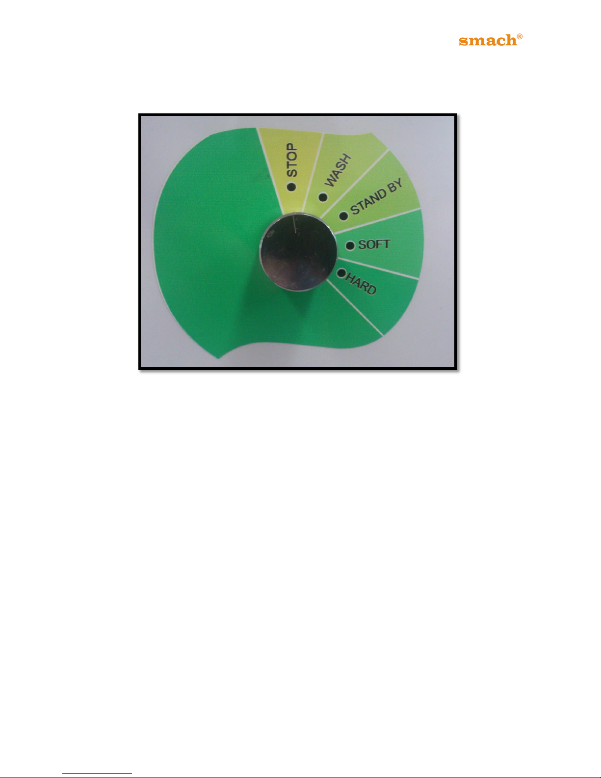
Figure 11
The CONTROL DIAL has the following selections:
STOP
In the STOP position, no refrigeration occurs in hopper and barrel.
WASH
In the WASH position the Soft-serve in the barrel will be agitated, however no refrigeration
will occur.
STAND-BY
In the STAND BY position the barrel will retain frozen product in a semi-soft state for
prolonged periods of non-use. Both barrel and hopper will be chilled.
SOFT / HARD
Choose the SOFT / HARD selection depending on the type of Soft-Serve Product you
have chosen and the consistency you find more preferable.
Page 23
22
EFE 2500A /AF - 4000A/AS/AN
11. OPERATING PROCEDURE
1. Always wash your hands with soap and potable water before assembling the machine.
(Preferably use new paper towels to dry your hands)
2. Only use the removable parts after they have been washed sanitized and air-dried.
3. Fit the beater assembly only when machine is off.
4. Follow all the instructions of this manual and the operating procedures of the store
owner, and at all times follow recognized in-store hygiene procedures, in particular those
in respect of dairy products.
5. Repairs must be done by the persons who are authorized by Smach®, if not, any
product failure warrantee will become invalid and void.
12. PREPARATION AND START UP PROCEDURE
12.1 PREPARATION
Make sure that all the removable parts have been washed with potable
water and sanitized, and then air dried before they are used.
Attention: NEVER ASSEMBLE OR DISASSEMBLE ANYTHING
UNLESS YOU HAVE:
1. Selected the STOP Mode.
2. Switched off the power at the wall and un-plugged the power cable.
Page 24
23
EFE 2500A /AF - 4000A/AS/AN
You must use food grade lubricant to do the assembly described below.
Prepare the mixture as shown in product description.
12.2 STARTING THE MACHINE
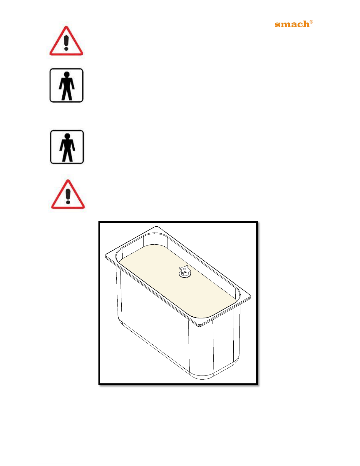
Fill the hopper with the mix, up to half level of the hopper. Let the Barrel fill
up with the mix. Wait till all the air has bubbled out of the barrel. The barrel
will be full when the bubbling stops. Then place the air tube and fill the
hopper.
Fill the hopper, up to the level of upper hole of the air tube.
Do NOT fill above the upper hole of the air tube. (Figure 12)
Figure 12
Page 25
24
EFE 2500A /AF - 4000A/AS/AN
Close the hopper cover and turn the freezer to WASH mode again and wait
2 minutes. Then discharge ice cream to take out pressure. Otherwise, the
barrel can freeze and it may damage the freezer.
After taking the pressure out, the freezer is ready to use. Place the Hopper
Cover, turn the control dial to SOFT or HARD mode and wait till the freezing
down has completed. The Freezer will stop and become quiet when the
Soft-serve is frozen down for the selected state of SOFT or HARD. (Once
the machine has reached the selected hardness the refrigeration
compressor will automatically stop for pre-set intervals).
12.3 DISPENSING ICE CREAM
After the Freezer has frozen down and stopped, pull the Dispensing Handle
and dispense about 300 grams of Soft-Serve into a washed and sanitized
beaker. (Discard the Soft-serve if not used immediately).
NOTICE: The temperature of the Soft-serve should be between: -6.5ºC
and -8.0ºC.
When a serve is dispensed the Freezer is automatically activated by the movement
detector switch when it senses the cone in hand being held below the dispense head
nozzle.
13. STEP-BY-STEP CLEANING - SANITIZING PROCEDURE
When properly used and cared for the machine will provide a consistent
quality Soft-Serve or Frozen Yoghurt. Like all equipment used to
manufacture food products it will require daily cleaning and regular
maintenance. A specified amount of care and attention is required
including but not limited to everything prescribed in this manual.
Attention: Because of bacteria population increases very fast, cleaning
and sanitizing is vital. Extra attention must be given for cleaning and
sanitizing properly.
Page 26
25
EFE 2500A /AF - 4000A/AS/AN
13.1 CLEANING PROCEDURE
Follow these steps for cleaning: (All water used must be potable water)
1. Firstly take off air tube.
2. Close the hopper cover, turn the machine to the “WASH” mode and wait 3 minutes.
3. Place an empty container under the dispense head and drain the remaining Soft-
Serve and liquid into a clean, sanitized bucket. Immediately place a tight sealing lid
onto the bucket and store refrigerated. (preferably below 5ºC)
4. Fill the hopper with cold water and allow the machine to run for 2-3 minutes before
draining the water into the bucket.
5. Fill the hopper with warm water. Allow the machine to run for approximately 5
minutes before draining the liquid into the bucket.
6. Repeat step 4 until the water runs clear.
7. Set the control dial to STOP mode and then switch off the power at the wall socket
and unplug the power cable.
8. Remove the screws of the Dispense Head.
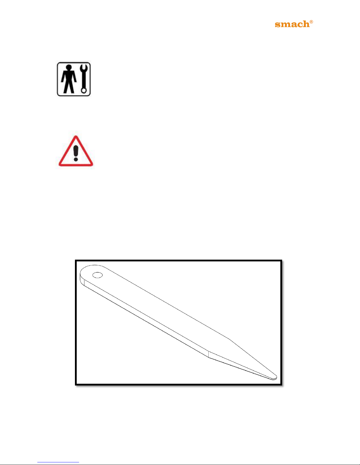
9. Remove and disassemble the Dispense Head, Piston, Beater and O-rings. (Please
use the O-ring remove apparatus. (Figure 13))
10. Remove and disassemble hopper agitator.
11. Remove the liquid level sensor. Remove the retaining ring and float.
12. Wash and sanitize hopper, barrel and all the removable parts according to the
sanitizer manufacturer’s instructions and allow the parts to air-dry. Do not use any
chemicals other than the approved Sanitizer during the cleaning process.
13. Assemble all the parts, ensuring the O-rings and their groves are properly lubricated.
14. Start by lubricating the harmonica-shaped Beater Shaft seal and slip it onto the
beater shaft:
a. Place the beater into the barrel and turn it slowly until it locks into position.
b. Lubricate the smaller O-rings, slip them onto the piston and place the piston
into the dispense head.
c. Lubricate the large O-ring and place into the back of the dispense head.
15. Place the dispense head back onto the machine and tighten the screws in a cross-
wise manner.
Do NOT touch barrel feeder hole during the cleaning process!
Page 27
26
EFE 2500A /AF - 4000A/AS/AN
For optimal machine-performance, the condenser must be cleaned from
dust and dirt regularly by an authorized technician.
Dispensing head nozzle must be cleaned and sanitized every 6 hours.
For water-cooled machines, the filter must be cleaned every 3 months.
Figure 13
Page 28
27
EFE 2500A /AF - 4000A/AS/AN
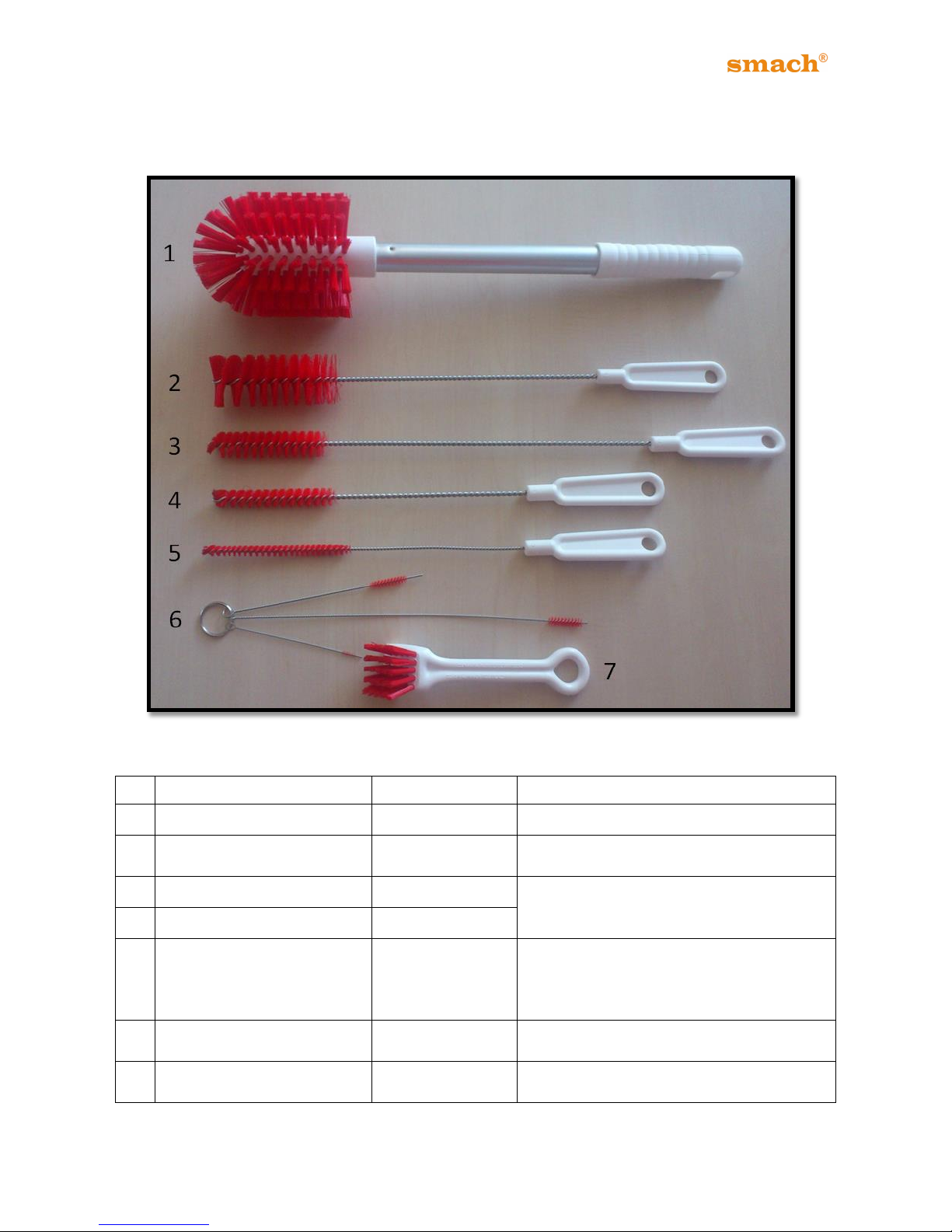
13.2 BRUSH CLEANING PROCEDURE
*Optional – Smach® highly recommends the brush set for a proper detailed cleaning.
Figure 14
No
Part Name
Product Code
Area of Usage
1
Brush - Ø90x120x440
19506002
Barrel, Hopper, Drip Tray
2
Brush - Ø40 x100x400
19506003
Head (Piston Grove), Barrel Feeder
Hole
3
Brush - Ø20x90x450
19506004
Pump cover and Pump body holes,
Outer Air Tube, Scrapper Blades,
Pusher, Dasher, Head Screw Holes
4
Brush - Ø15x90x350
19506005
5
Brush – Ø9x110x350
19506006
Barrel Feeder Hole, Pump Feeder
Tube, Inner Air Tube, Compression
Feed Pipe, Head (Motion Pin Hole),
Liquid Level Sensor
6
Triple Brush - Ø6 Ø5 Ø2
19506007
Pump Cover, Pump Feeder Tube, Air
Tube, Compression Feed Pipe, Head
7
Hand Brush - 30x35x170
19506008
Nozzle, Head (Back Side), Drip Tray,
Pump
Table 8
Page 29
28
EFE 2500A /AF - 4000A/AS/AN
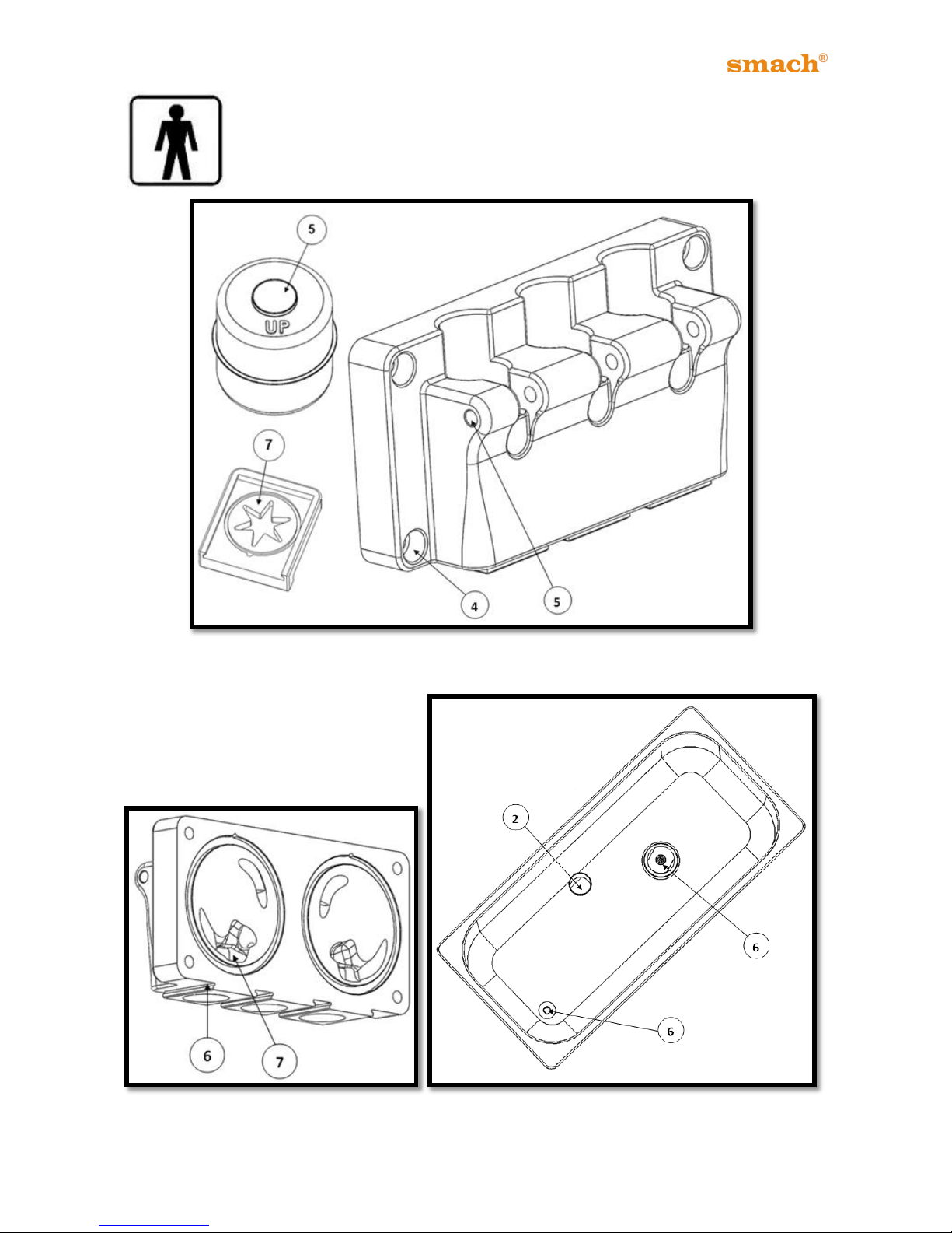
Make sure all brushes provided with the freezer are available for brush
cleaning.
Figure 15
Figure 16 Figure 17
Page 30
29
EFE 2500A /AF - 4000A/AS/AN
13.3 SANITIZING PROCEDURE
After cleaning procedure, hopper, barrel and all the removable parts must
be sanitized. It is recommended to use approved “SMACH
®
Sanitizer”
during disinfection. (Please contact SMACH® to provide approved
“SMACH
®
Sanitizer”.)
The SMACH® sanitizer is based on alcohol and QAC.
It is suitable for metals against corrosion.
It provides a fast and effective disinfection.
It is a volatile material, so it leaves no residue on the applied surface.
- Keep out of reach of children.
- Rinse well after application.
- Avoid eye contact. In case of contact, wash with water immediately.
- Avoid skin contact.
- Do not use for face, body, hand and food cleaning.
- Keep in a cool place.
- Do not expose to direct sunlight.
Directions to Use
It is a ready to use solution. Apply through spraying and wiping. It is recommended to wait
at least 5 minutes after spraying.
The sanitizing solution mustn’t be mixed with water.
During cleaning and sanitizing, follow all instructions given in this User
Guide, otherwise, Smach® Gıda Makine A.Ş will not take any responsibility
of unwanted results.
Page 31
30
EFE 2500A /AF - 4000A/AS/AN
14. STEP-BY-STEP ASSEMBLY PROCEDURE
14.1 DISPENSING HEAD ASSEMBLY
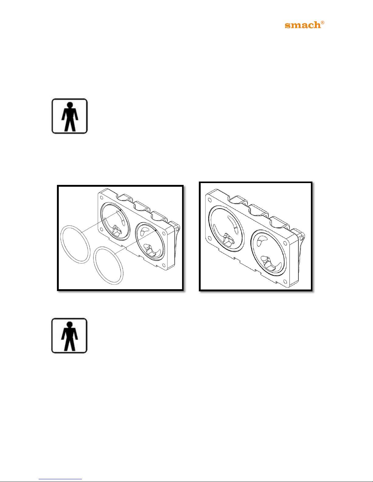
14.1.1 Dispensing Head O-Ring Assembly:
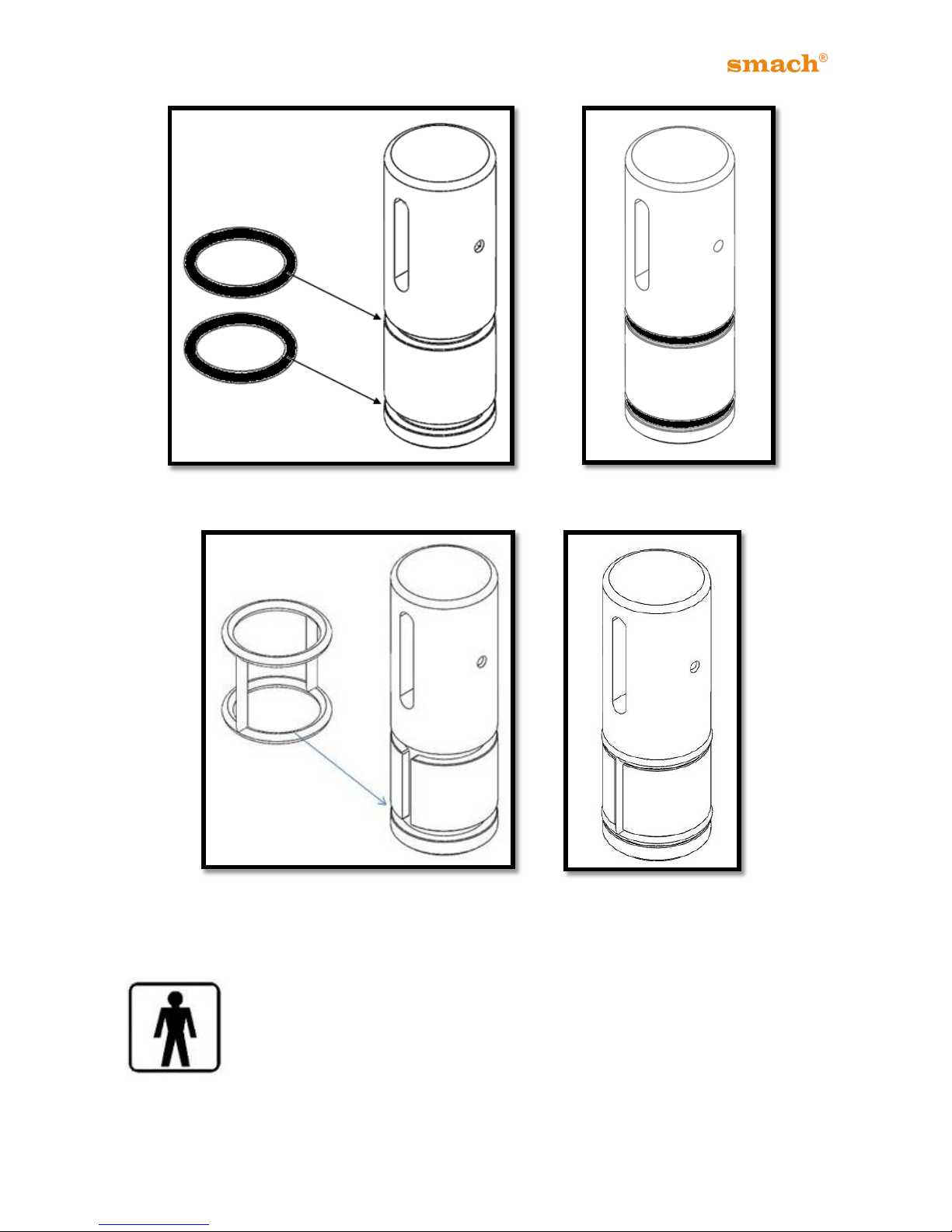
Place a small amount of lubricant onto your index- and middle finger and
hold the large DISPENSING HEAD SEAL O-RING between the lubricated
fingers and your thumb. Gently pull the O-ring through your lubricated
fingers until it is entirely covered. The coating of lubricant should be thicker
than on the piston as it will prevent the O-ring from slipping during the later
stages of the assembly. Place the O-ring gently into the designated groove of the
Dispensing head and press firmly into place.
Figure 18 Figure 19
14.1.2 Dispensing Head Piston – O-Ring Assembly: Assemble the
Dispensing Head piston using food grade lubricant. Slip the appropriate O-
rings onto the piston.
Place a small amount of lubricant onto your middle and index finger and
evenly coat the piston’s entire surface. The coating must be all-encompassing but must
not be too thick; a very thin layer will suffice.
.
Page 32
31
EFE 2500A /AF - 4000A/AS/AN
Figure 20 Figure 21
Figure 22 Figure 23
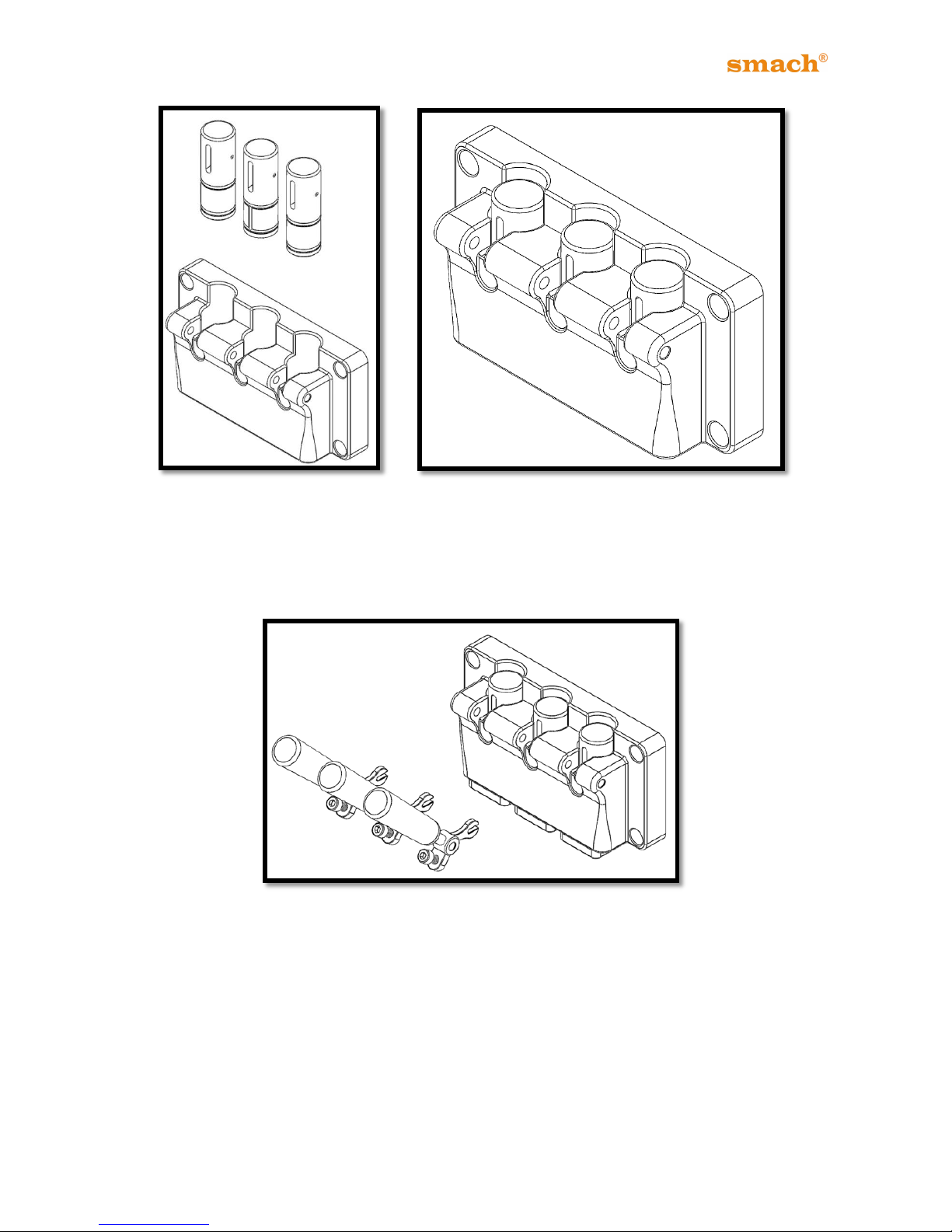
14.1.3 Dispensing Head Piston Assembly:
Insert the lubricated piston into the dispense head. This motion should be
quite free and without too much force. If the piston does not move freely, a
little more Lubricant is required.
In that case, remove the piston, add a little more lubricant as prescribed
above and re-insert.
Page 33
32
EFE 2500A /AF - 4000A/AS/AN
Figure 24 Figure 25
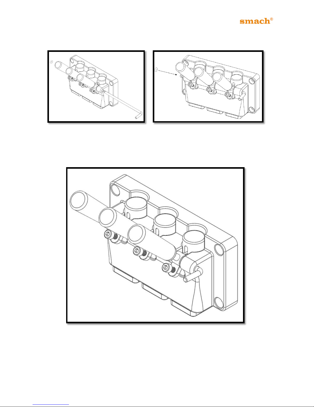
14.1.4 Dispensing Head Piston Lifter Assembly:
Figure 26
Page 34
33
EFE 2500A /AF - 4000A/AS/AN
14.1.5 Dispensing Head Lifter Rod Assembly:
Figure 27 Figure 28
14.1.6 Dispensing Head Assembled:
Figure 29
Page 35
34
EFE 2500A /AF - 4000A/AS/AN
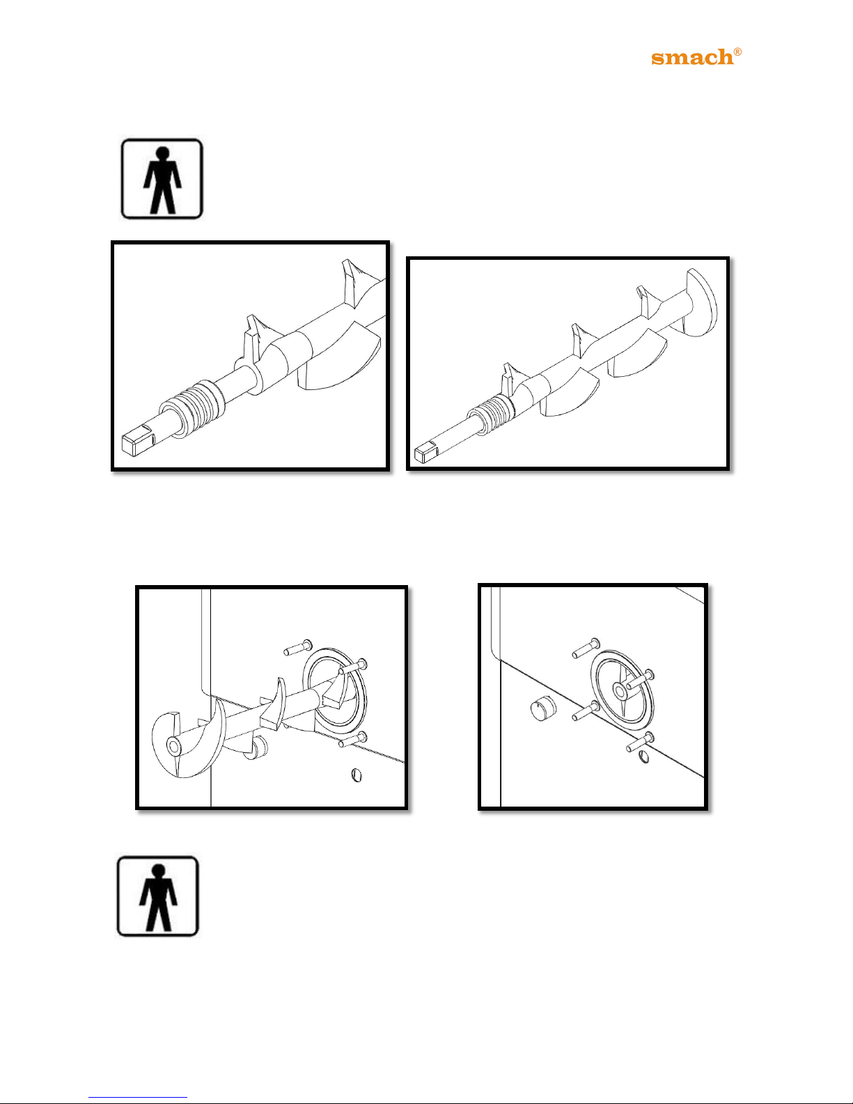
14.2 BEATER ASSEMBLY
14.2.1 Seal Assembly: Lubricate the TWO faces of the Beater Drive Shaft
Seal and slip over the drive shaft.
Figure 30 Figure 31
14.2.2 Inserting the Beater into the Barrel
Figure 32 Figure 33
Make sure the barrel is free of any obstruction before you insert the beater.
The beater must slide in easily with a final firm push and some turning to
align the shaft with the gearbox socket.
When it is pushed in, the beater seal will push it out a few millimeters like a
spring. Do not be concerned about this, as you place the dispensing head
on, the dispense head will push it into position.
Page 36
35
EFE 2500A /AF - 4000A/AS/AN
14.3 FITTING THE ASSEMBLED DISPENSING HEAD
Figure 34 Figure 35
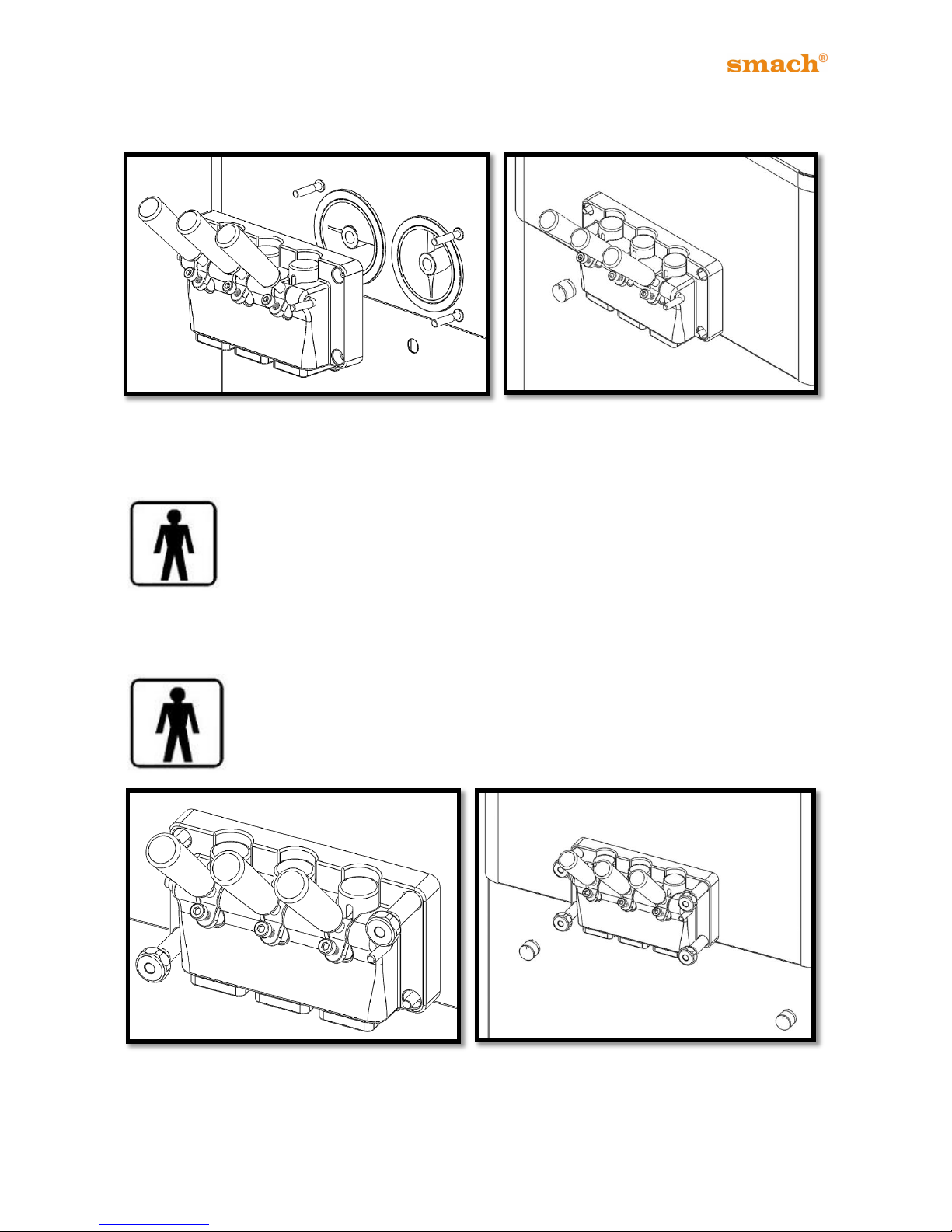
14.3.1 Placing the Dispense Head:
Place the dispense head over the 4 fitting bolts. Make sure the dispense
handle is in the UP position so Soft-Serve liquid does not run out.
14.3.2 Tightening the Screws:
Tighten the 4 Dispense Head Screws in a cross order (i.e., left-hand top
and right-hand bottom and then right-hand top and left-hand bottom.
Figure 36 Figure 37
Page 37
36
EFE 2500A /AF - 4000A/AS/AN
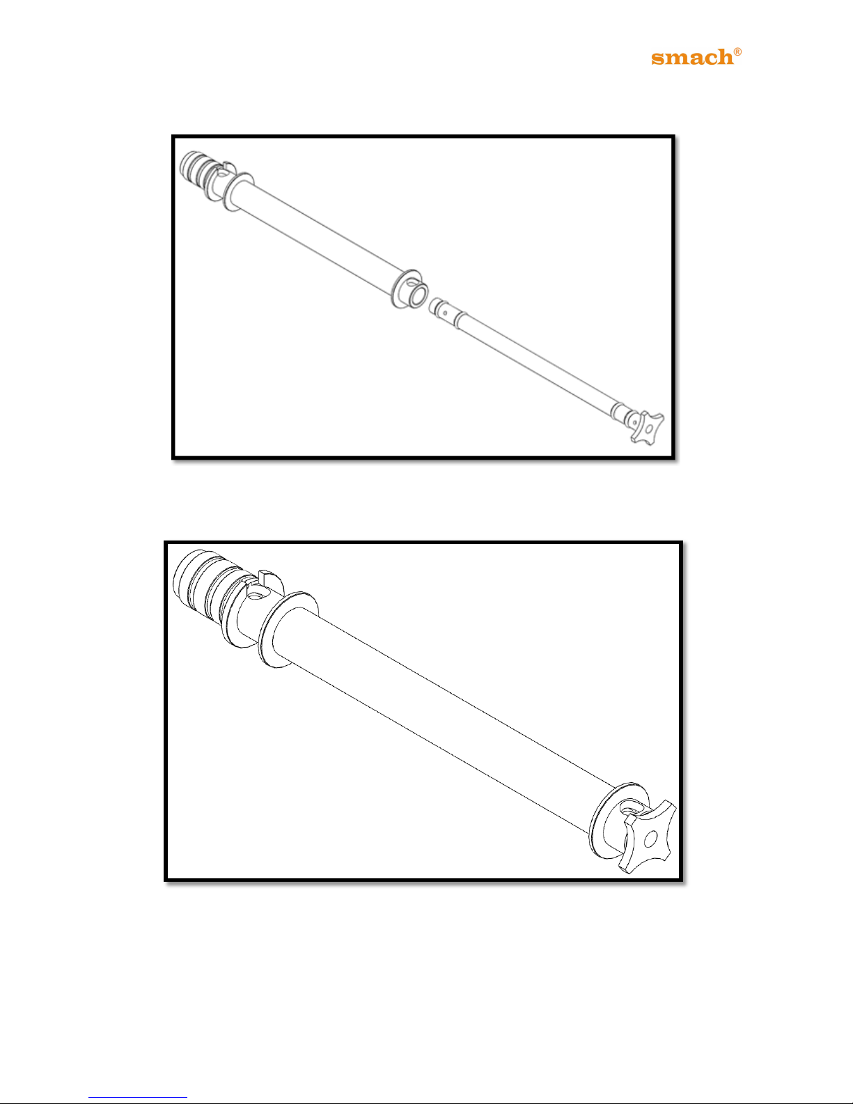
14.4 ASSEMBLY OF THE AERATION TUBE
Figure 38
Grease and fit the o-rings to the slots on the inner and outer aeration tubes.
Figure 39
Slip two parts to each other. Select the suitable hole size by turning the inner tube.
Page 38
37
EFE 2500A /AF - 4000A/AS/AN
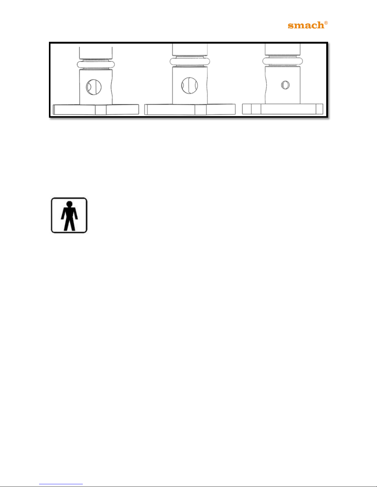
Figure 40
The INNER tube has 3 different size holes. The inner aeration tube could be turned inside
the outer, to select SMALL, MEDIUM or LARGE hole. (Figure 40)
The selection of the correct inner tube hole-size depends on the product that is run
through the Soft-Serve Freezer and what amount of aeration is desired.
The SMALL HOLE will increase air percentage in the Soft-Serve and yield
higher overrun.
The MEDIUM HOLE will result in an average air percentage and yield a
medium overrun.
The LARGE HOLE for will decrease the air percentage and yield a lower
overrun.
The LARGE HOLE setting may also be required for high-viscosity (thick) liquid mixes.
Page 39
38
EFE 2500A /AF - 4000A/AS/AN
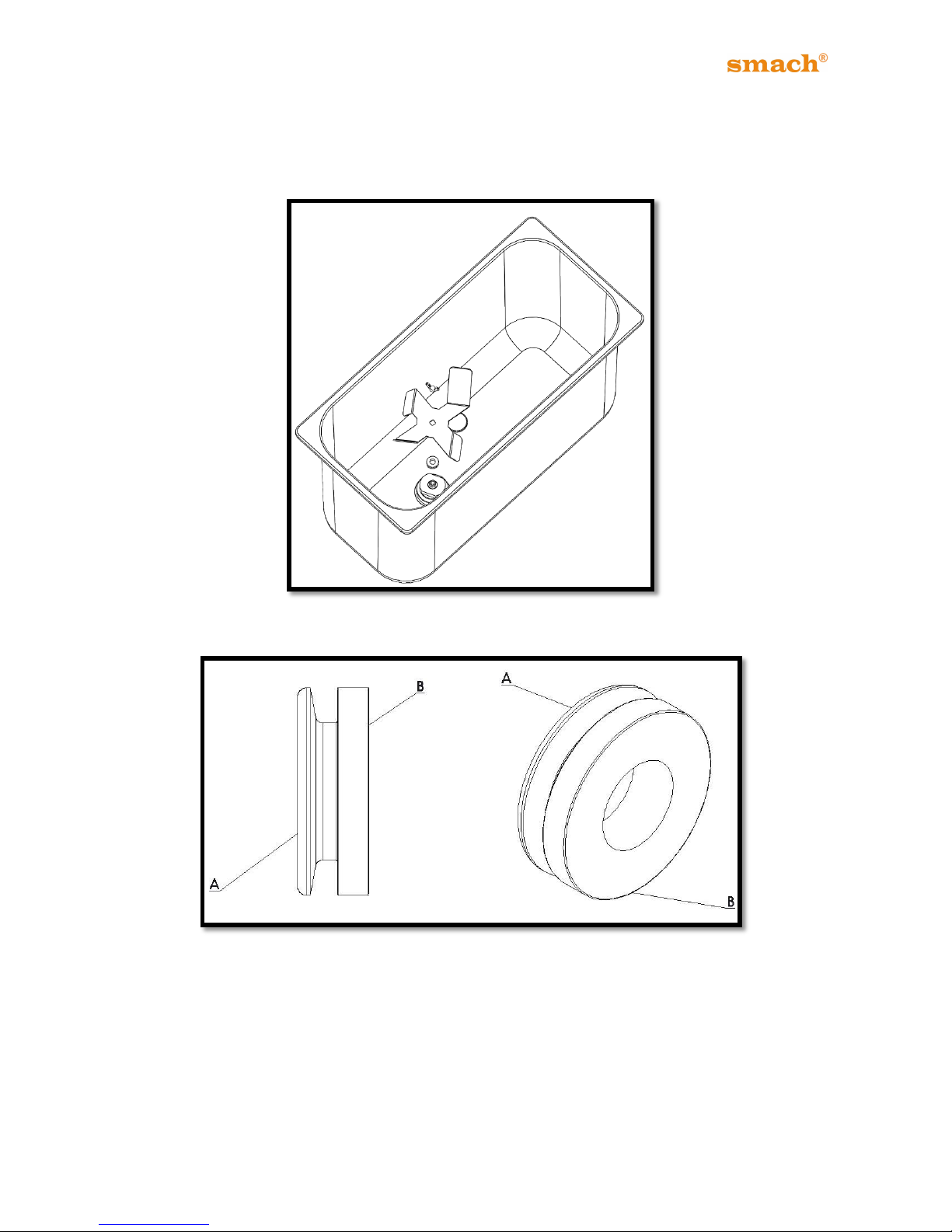
14.5 ASSEMBLY OF HOPPER AGITATOR TO THE MACHINE
Figure 41
Figure 42
Page 40
39
EFE 2500A /AF - 4000A/AS/AN
Figure 43
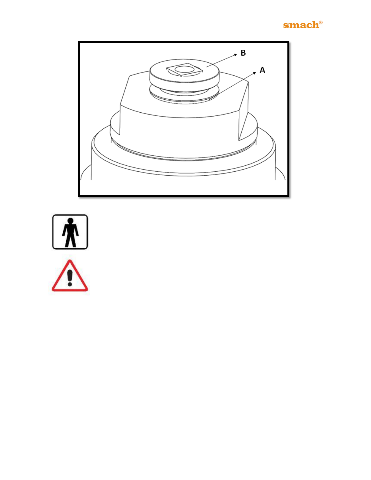
Lubricate the Agitator Seal and place it on the Agitator shaft.
Check the position of the seal. It must be placed as shown in the picture.
Page 41
40
EFE 2500A /AF - 4000A/AS/AN
Figure 44 Figure 45
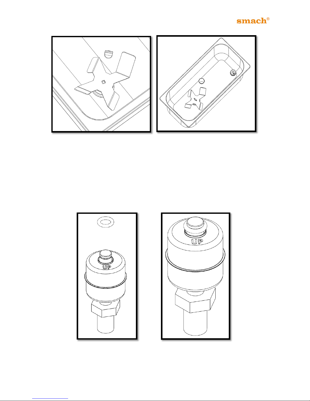
After placing Agitator Seal, place the Agitator Blades and tighten it with the Wing Screw.
14.6 LIQUID LEVEL SENSOR ASSEMBLY
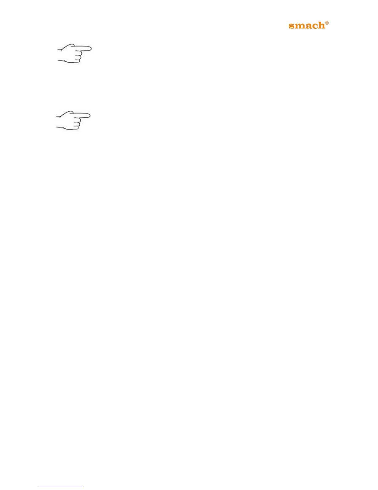
Place the liquid level sensor float on the body. Make sure the float is placed correctly. The
up side of the float is marked as shown in the picture. After placing float, place the O-Ring
to the groove.
Figure 46 Figure 47
Page 42
41
EFE 2500A /AF - 4000A/AS/AN
If there isn’t enough mix in the hopper, the machine will alert you by voice
and flashing light.
14.7 HOPPER COVER ASSEMBLY
Place the HOPPER COVER in position. You should place the Hopper
Cover before running the machine. Otherwise the machine will lock itself
and won’t run.
15. POSSIBLE FAILURES AND SOLUTIONS
Attention: DO NOT ALLOW ANY TECHNICAL MAINTENANCE OR REPAIRS BEFORE
DISCONNECTING THE FREEZER FROM THE POWER SUPPLY.
If the solutions listed below in the Trouble Shooting guide do not resolve your operational
problems, call an authorized service agent for further assistance.
Page 43
42
EFE 2500A /AF - 4000A/AS/AN
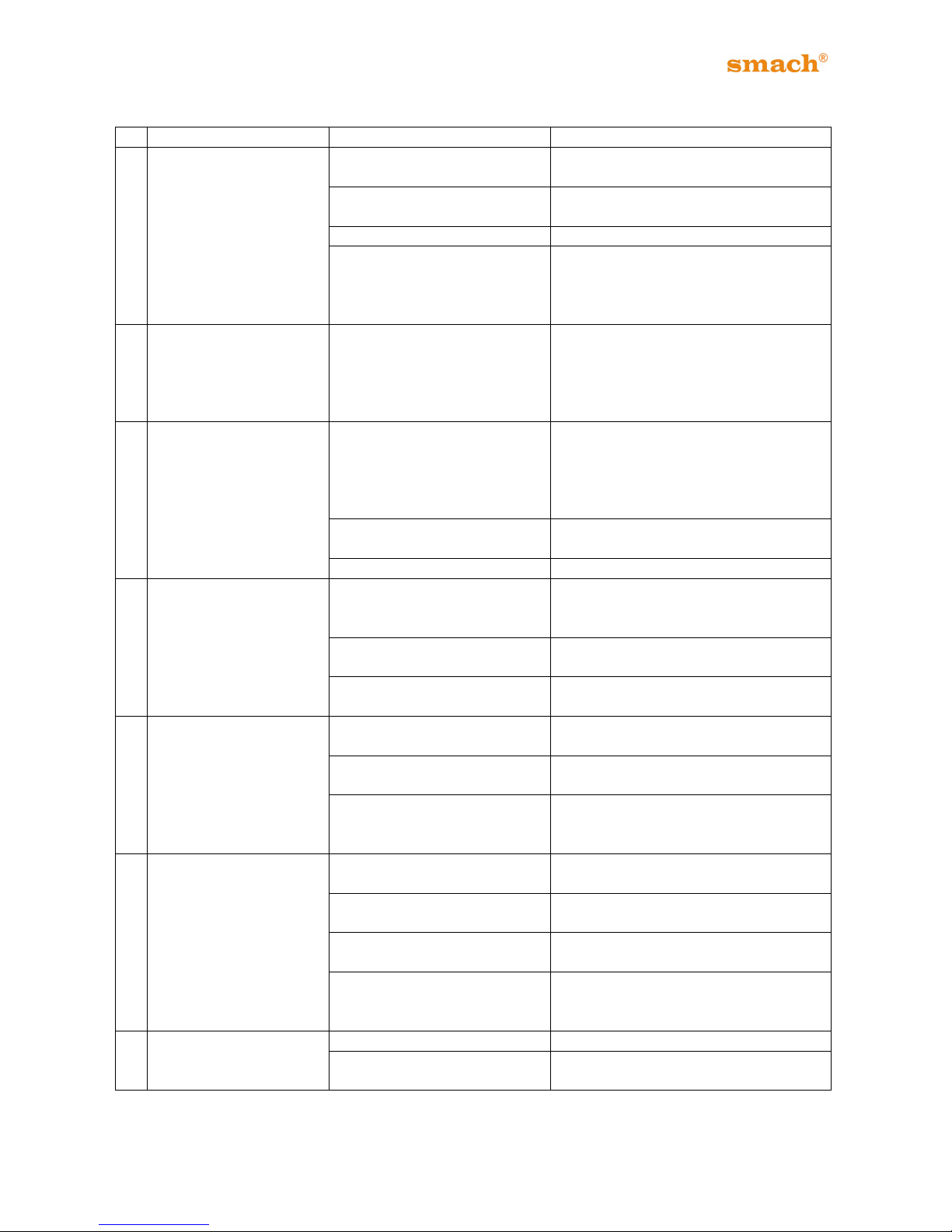
TROUBLESHOOTING GUIDE
Problem
Cause
Solution
1
Machine does not run
No electricity//power
Check if plugged in and switch on at wall
socket.
Dispensing Head hasn’t been
assembled properly.
Ensure that, the head is assembled
properly.
No mix in the hopper.
Re-fill the hopper.
There is voltage fluctuation.
Plug off and wait for 30 seconds and
plug on again.
Check if there is another machine is
connected in the same socket.
2
Compressor starts, then
stops after a few
seconds.
a) Air-cooled machine: No air
circulation
b) Water-cooled machine: No
water circulation
a)Check the clearances around the
machine.
b)Check the water inlet, outlet and filter.
Check that pipe is not squashed nor
bent.
3
Machine fails to cut-off
when running on SOFT
or HARD mode
a) Air-cooled machine: Air
circulation is restricted.
b) Water-cooled machine:
Water circulation is restricted.
a)Check the clearances around the
machine.
b)Check the water inlet, outlet and filter.
Check that pipe is not squashed nor
bent.
Too much air in the freezerbarrel.
Open Dispense head and drain-off ½
liter of product.
No mix in the Hopper
Re-fill the Hopper
4
Machine works, but no
product comes from the
Dispense Head.
Dispense head is blocked with
ice.
Place the machine onto Wash mode and
allow the product to thaw. Remove 1 liter
mix and re-start the machine.
Mixing instuctions of Soft-serve
was not followed
Drain the machine and re-fill with proper
mix.
The frozen product is too hard.
Set the Control Dial to Wash mode and
allow the product to soften.
5
Machine runs, but
Product is too soft
Mixing instuctions of Soft-serve
was not followed
Drain the machine and re-fill with proper
mix.
Machine remained idle without
dispensing product for too long.
Remove 1 liter of frozen product and
allow the machine to recover.
Too much frozen product is
dispensed at a time.
Allow the machine to recover; then
continue to draw within the productionlimits for this model.
6
Mix leaks from the
Dispense Head
Piston O-rings are missing
Drain the machine and add piston Orings
Piston O-rings are worn
Drain the machine and replace the
piston O-rings
Dispense Head O-ring is
missing or displaced
Drain the machine and add or adjust Oring
Dispense Head bolts are not
tightened sufficiently or are
tightened unevenly
Tighten Disphense head screws evenly
and properly
7
Mix leaks from the Drip
Tube
Beater-seal is missing
Drain the machine and add Beater-Seal
Beater-seal is worn
Drain the machine and replace beaterseal.
Page 44
43
EFE 2500A /AF - 4000A/AS/AN
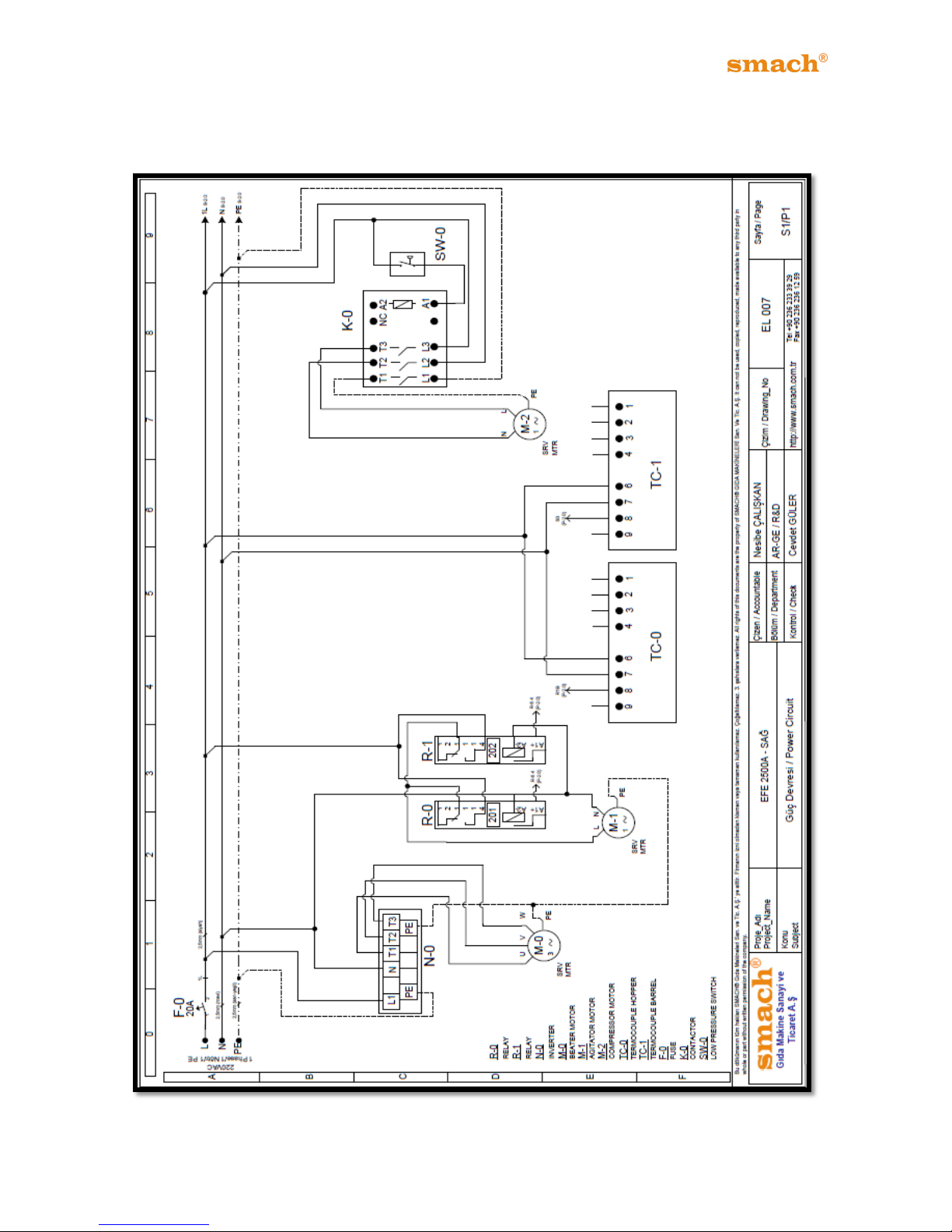
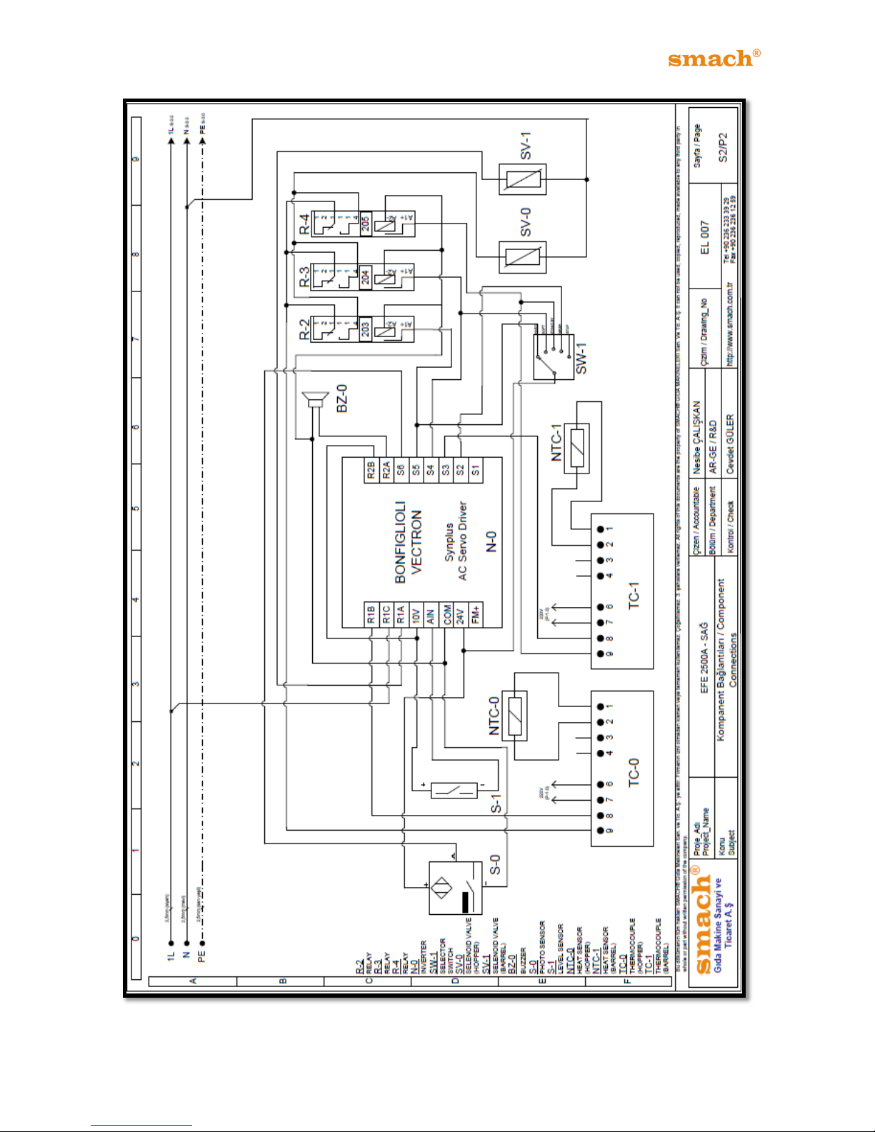
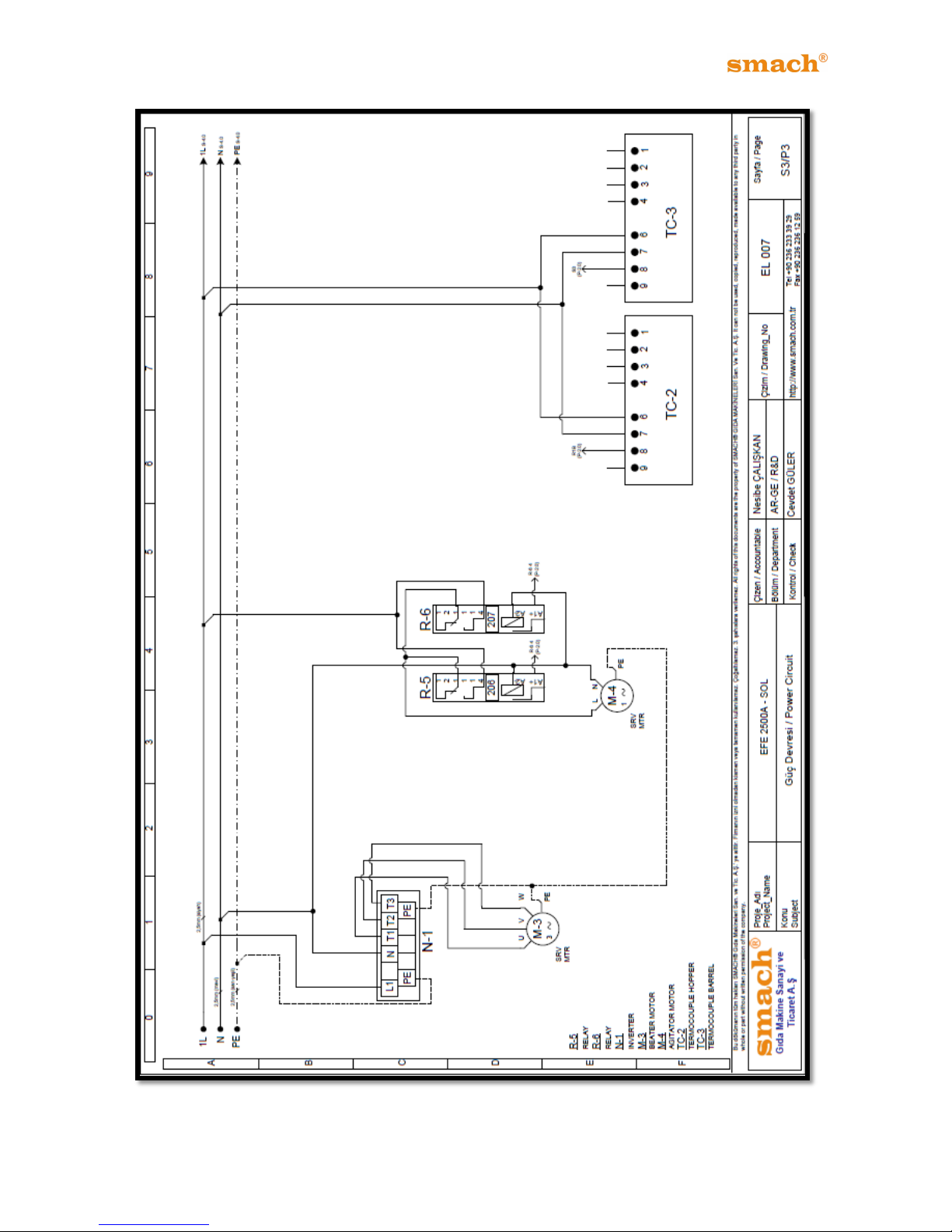
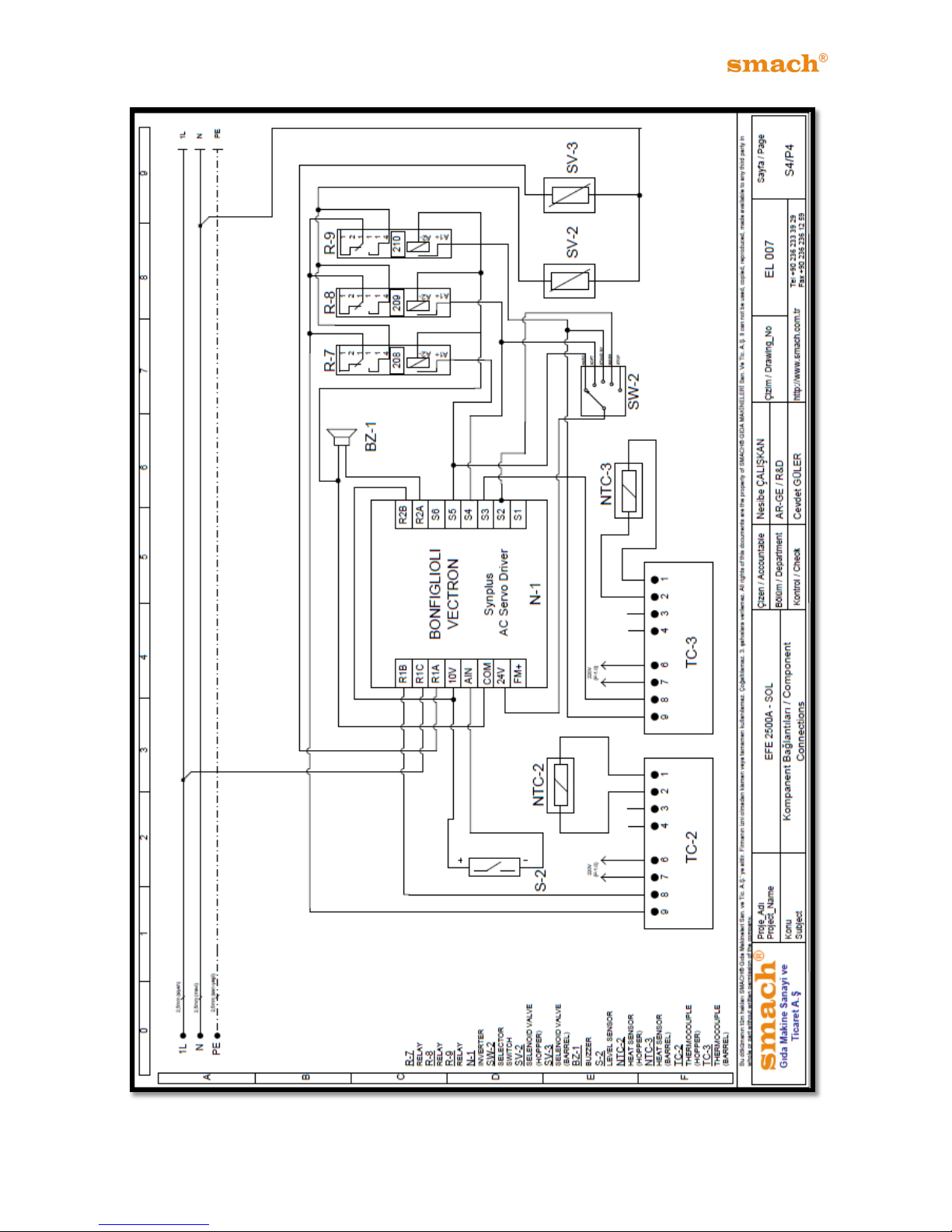
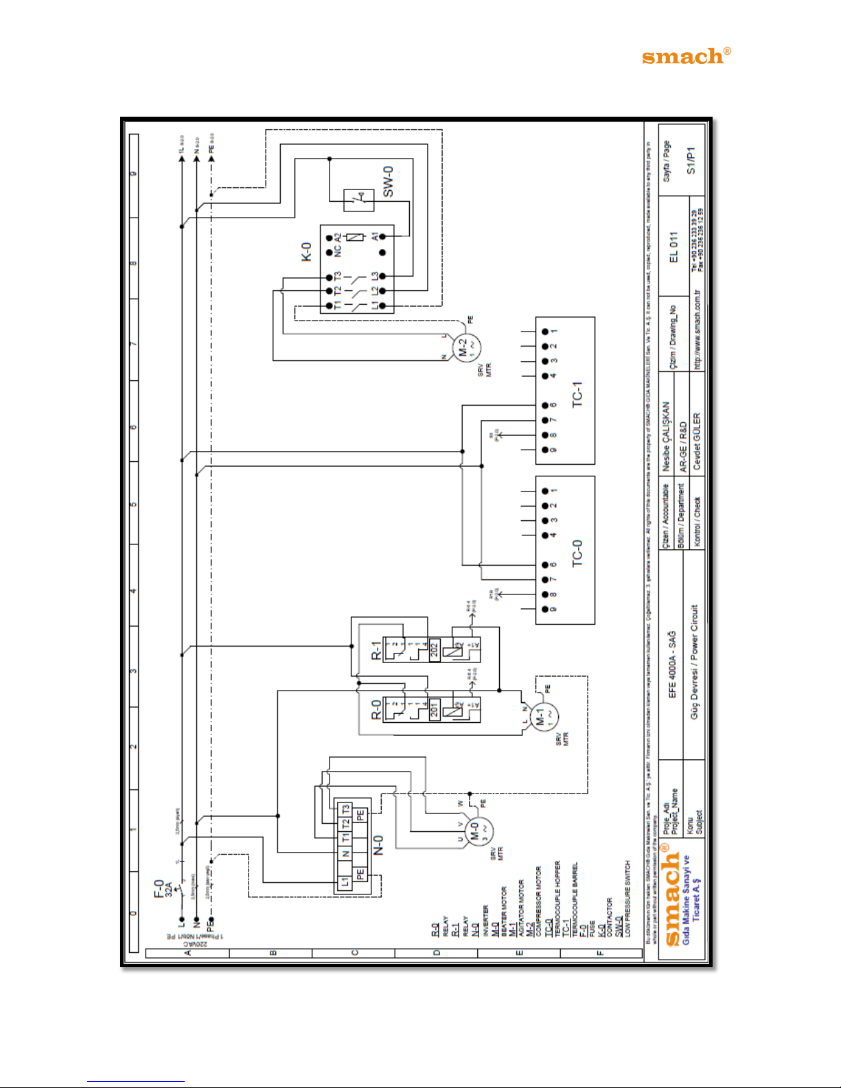
16. ELECTRICAL CIRCUIT DIAGRAMS
16.1 EFE 2500A/AF
Figure 48
Page 45
44
EFE 2500A /AF - 4000A/AS/AN
Figure 49
Page 46
45
EFE 2500A /AF - 4000A/AS/AN
Figure 50
Page 47
46
EFE 2500A /AF - 4000A/AS/AN
Figure 51
Page 48
47
EFE 2500A /AF - 4000A/AS/AN
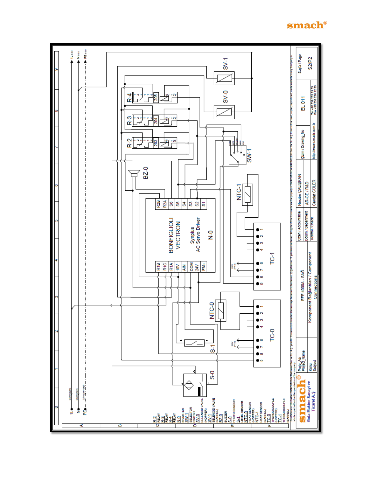
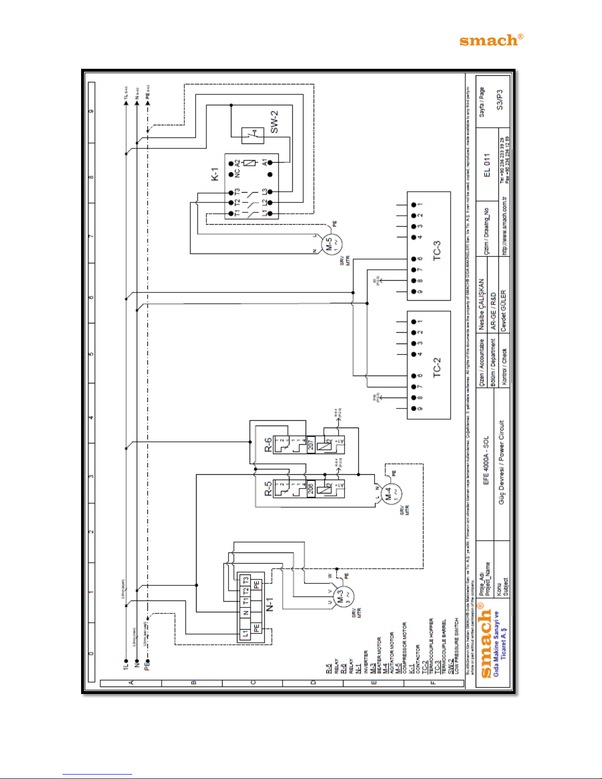
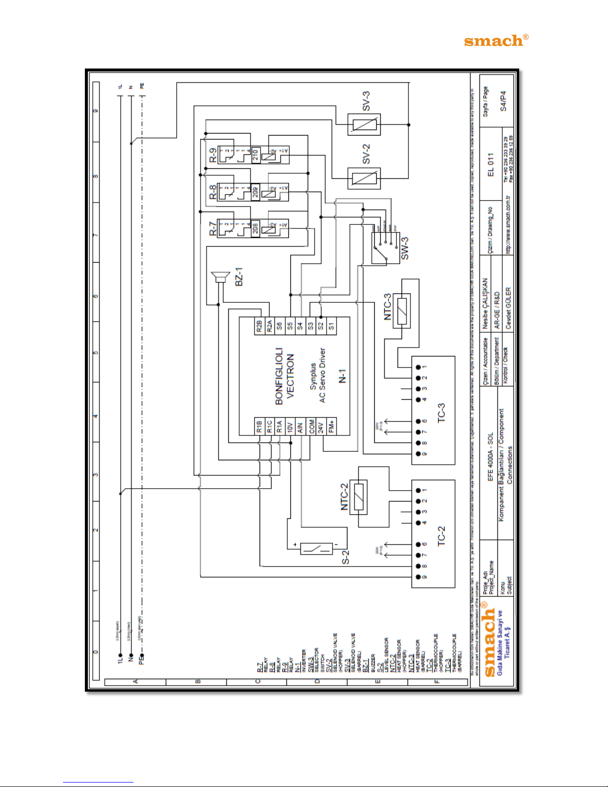
16.2 EFE 4000A/AS/AN
Figure 52
Page 49
48
EFE 2500A /AF - 4000A/AS/AN
Figure 53
Page 50
49
EFE 2500A /AF - 4000A/AS/AN
Figure 54
Page 51
50
EFE 2500A /AF - 4000A/AS/AN
Figure 55
Page 52
WARRANTY DOCUMENT AND CONDITIONS
MANUFACTURER
ADRESS: GUZELYURT MAH.5762 Sok.No:5/A
ORTA OLCEKLI SANAYI BOLGESI
MANISA
Tel: +90 236 233 39 29 / +90 236 233 62 04
Fax: +90 236 236 12 59
WARRANTY
MODEL NO: EFE 2500A / 4000A/AS
International Warranty Period: 1 Years
Invoice Date/No:
Delivery Date:
SEAL&SIGNATURE
This warranty given by SMACH® GIDA MAKINE SAN.TIC.A.S does not apply in the following cases:
1) The failures results from misusage of product or usage of other applications.
2) After the delivery, the failures resulted from moving, carrying of the machine.
On the condition that any distortions made on warranty or on the serial number the
product will be out of the warranty.
 Loading...