

SMA SUNNY ISLAND SIC40-MPT Technical Description

Charge controller
SUNNY ISLAND CHARGER
Technical Description
SIC40-TEN081110 | 98-2005210 | Version 1.0
EN


SMA Solar Technology AG Table of Contents
Table of Contents
1 Notes on this Manual. . . . . . . . . . . . . . . . . . . . . . . . . . . . . . 7
1.1 Validity . . . . . . . . . . . . . . . . . . . . . . . . . . . . . . . . . . . . . . . . . . . . 7
1.2 Target Group . . . . . . . . . . . . . . . . . . . . . . . . . . . . . . . . . . . . . . . 7
1.3 Storage of the Manual. . . . . . . . . . . . . . . . . . . . . . . . . . . . . . . . 7
1.4 Symbols Used. . . . . . . . . . . . . . . . . . . . . . . . . . . . . . . . . . . . . . . 8
2 Safety Precautions . . . . . . . . . . . . . . . . . . . . . . . . . . . . . . . . 9
2.1 Appropriate Usage . . . . . . . . . . . . . . . . . . . . . . . . . . . . . . . . . . 9
2.2 General Safety Instructions . . . . . . . . . . . . . . . . . . . . . . . . . . . 10
3 Unpacking. . . . . . . . . . . . . . . . . . . . . . . . . . . . . . . . . . . . . . 11
3.1 Packing List . . . . . . . . . . . . . . . . . . . . . . . . . . . . . . . . . . . . . . . . 11
3.2 Checking for Transport Damage . . . . . . . . . . . . . . . . . . . . . . . 11
3.3 Identification of the Charge Controller . . . . . . . . . . . . . . . . . . 12
4 Mounting. . . . . . . . . . . . . . . . . . . . . . . . . . . . . . . . . . . . . . . 13
4.1 Selection of Mounting Location . . . . . . . . . . . . . . . . . . . . . . . . 13
4.1.1 Dimensions . . . . . . . . . . . . . . . . . . . . . . . . . . . . . . . . . . . . . . . . . . . . . . . . . . 13
4.1.2 Ambient Conditions . . . . . . . . . . . . . . . . . . . . . . . . . . . . . . . . . . . . . . . . . . . 14
4.1.3 Safety Clearances . . . . . . . . . . . . . . . . . . . . . . . . . . . . . . . . . . . . . . . . . . . . 14
4.1.4 Position . . . . . . . . . . . . . . . . . . . . . . . . . . . . . . . . . . . . . . . . . . . . . . . . . . . . . 15
4.2 Mounting Instructions . . . . . . . . . . . . . . . . . . . . . . . . . . . . . . . . 15
5 Electrical Connection . . . . . . . . . . . . . . . . . . . . . . . . . . . . . 17
5.1 Overview of the Connection Area . . . . . . . . . . . . . . . . . . . . . . 18
5.2 Grounding . . . . . . . . . . . . . . . . . . . . . . . . . . . . . . . . . . . . . . . . 19
5.2.1 Grounding the Charge Controller . . . . . . . . . . . . . . . . . . . . . . . . . . . . . . . . 19
5.2.2 Grounding the Battery and the PV System. . . . . . . . . . . . . . . . . . . . . . . . . . 20
5.3 PV Generator (DC) Connection . . . . . . . . . . . . . . . . . . . . . . . . 21
5.4 Battery Connection (DC) . . . . . . . . . . . . . . . . . . . . . . . . . . . . . 23
Technical Description SIC40-TEN081110 3

Table of Contents SMA Solar Technology AG
5.5 Communication . . . . . . . . . . . . . . . . . . . . . . . . . . . . . . . . . . . . 25
5.5.1 Installing the Communication Interface . . . . . . . . . . . . . . . . . . . . . . . . . . . . 26
5.5.2 Connection of the Communication Interface . . . . . . . . . . . . . . . . . . . . . . . . 26
5.6 Additional Connections . . . . . . . . . . . . . . . . . . . . . . . . . . . . . . 27
5.6.1 Signalling Contact . . . . . . . . . . . . . . . . . . . . . . . . . . . . . . . . . . . . . . . . . . . . 27
5.6.2 Battery Temperature Sensor . . . . . . . . . . . . . . . . . . . . . . . . . . . . . . . . . . . . . 29
6 (First) Commissioning. . . . . . . . . . . . . . . . . . . . . . . . . . . . . 31
6.1 Configuration of the Charge Controller. . . . . . . . . . . . . . . . . . 31
6.1.1 Operating Mode . . . . . . . . . . . . . . . . . . . . . . . . . . . . . . . . . . . . . . . . . . . . . 31
6.1.2 Battery System . . . . . . . . . . . . . . . . . . . . . . . . . . . . . . . . . . . . . . . . . . . . . . . 32
6.1.3 Device Address. . . . . . . . . . . . . . . . . . . . . . . . . . . . . . . . . . . . . . . . . . . . . . . 32
6.1.4 Battery Type . . . . . . . . . . . . . . . . . . . . . . . . . . . . . . . . . . . . . . . . . . . . . .33
6.2 Commissioning . . . . . . . . . . . . . . . . . . . . . . . . . . . . . . . . . . . . . 33
7 Opening and Closing. . . . . . . . . . . . . . . . . . . . . . . . . . . . . 34
7.1 Opening the Charge Controller. . . . . . . . . . . . . . . . . . . . . . . . 34
7.2 Closing the Charge Controller. . . . . . . . . . . . . . . . . . . . . . . . . 34
8 Battery Management and Charge Control . . . . . . . . . . . 35
8.1 SMA Operation . . . . . . . . . . . . . . . . . . . . . . . . . . . . . . . . . . . . 35
8.2 Stand-alone Operation . . . . . . . . . . . . . . . . . . . . . . . . . . . . . . 35
9 Maintenance and Cleaning. . . . . . . . . . . . . . . . . . . . . . . . 36
9.1 Replacing the Thermal Fuses . . . . . . . . . . . . . . . . . . . . . . . . . . 36
9.2 Cleaning the Cooling Fins . . . . . . . . . . . . . . . . . . . . . . . . . . . . 36
10 Parameter Lists on the Sunny Island . . . . . . . . . . . . . . . . 37
10.1 Display Values . . . . . . . . . . . . . . . . . . . . . . . . . . . . . . . . . . . . . 37
10.2 Events . . . . . . . . . . . . . . . . . . . . . . . . . . . . . . . . . . . . . . . . . . . . 39
10.3 Error (Warnings) . . . . . . . . . . . . . . . . . . . . . . . . . . . . . . . . . . . 39
4 SIC40-TEN081110 Technical Description

SMA Solar Technology AG Table of Contents
11 Explanation of the LEDs (With Codes) . . . . . . . . . . . . . . . 41
11.1 Multicolored LED . . . . . . . . . . . . . . . . . . . . . . . . . . . . . . . . . . . 41
11.2 Internal LEDs. . . . . . . . . . . . . . . . . . . . . . . . . . . . . . . . . . . . . . . 41
12 Decommissioning . . . . . . . . . . . . . . . . . . . . . . . . . . . . . . . . 42
12.1 Disassembly . . . . . . . . . . . . . . . . . . . . . . . . . . . . . . . . . . . . . . . 42
12.2 Packaging. . . . . . . . . . . . . . . . . . . . . . . . . . . . . . . . . . . . . . . . . 42
12.3 Storage. . . . . . . . . . . . . . . . . . . . . . . . . . . . . . . . . . . . . . . . . . . 42
12.4 Disposal . . . . . . . . . . . . . . . . . . . . . . . . . . . . . . . . . . . . . . . . . . 42
13 Technical Data . . . . . . . . . . . . . . . . . . . . . . . . . . . . . . . . . . 43
14 Contact . . . . . . . . . . . . . . . . . . . . . . . . . . . . . . . . . . . . . . . . 47
Technical Description SIC40-TEN081110 5

SMA Solar Technology AG
6 SIC40-TEN081110 Technical Description

SMA Solar Technology AG Notes on this Manual
1 Notes on this Manual
The manual describes how to install, commission and service the Sunny Island Charger.
1.1 Validity
This manual applies to the following Sunny Island Charger type:
• SIC40-MPT
The device type of your charge controller is specified on the type label as shown in section 3.3
"Identification of the Charge Controller" (Page 12).
1.2 Target Group
This manual is intended for installers and users.
1.3 Storage of the Manual
All manuals for the device and for the installed components must be stored in the immediate vicinity
of the charge controller, and must be accessible at all times.
Technical Description SIC40-TEN081110 7
Notes on this Manual SMA Solar Technology AG
1.4 Symbols Used
The following types of warnings and general information appear in this document as described
below.
DANGER!
DANGER indicates a hazardous situation which, if not avoided, will result in death or
serious injury.
WARNING!
WARNING indicates a hazardous situation which, if not avoided, could result in death
or serious injury.
CAUTION!
CAUTION indicates a hazardous situation which, if not avoided, could result in minor or
moderate injury.
NOTICE!
NOTICE indicates a situation that can result in property damage if not avoided.
Information
Information provides tips that are valuable for the optimal installation and operation of
your product.
8 SIC40-TEN081110 Technical Description
SMA Solar Technology AG Safety Precautions
2 Safety Precautions
2.1 Appropriate Usage
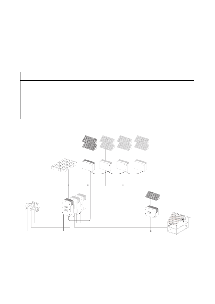
The charge controller is a DC/DC converter that reduces the direct current of the PV generator to
the direct current of a battery in order to charge it.
The charge controller can be operated in two different operating modes:
SMA operation Stand-alone operation
The "SMA" operating mode must be selected if
the charge controller is operated in a system
equipped with a Sunny Island 5048/2012 or
2224.
Section 6.1.1 "Operating Mode" (Page 31) explains how to set the operating mode.
Principle of a Sunny Island system equipped with a charge controller
Battery
The "Stand-alone" operating mode must be
selected if the charge controller is operated in a
stand-alone grid system equipped with a
Sunny Island 3324/4248 or without a
Sunny Island.
Charge controller
Generator
The charge controller may only be operated with PV generators (modules and cabling) of
protection class II. Do not connect any energy sources other than PV modules to the charge
controller.
As soon as you begin planning the PV system, ensure that the values comply with the permitted
operating range of all components at all times.
Technical Description SIC40-TEN081110 9
Sunny Island
Sync bus
(CAN)
Sunny Boy
Safety Precautions SMA Solar Technology AG
The maximum open circuit voltage of the PV generator may not be greater than the maximum input
voltage of the charge controller (140 V), even at very low ambient temperatures. During operation,
the PV generator voltage must always be at least 5 V higher than the battery voltage. The charge
controller is suitable for battery currents up to maximum 40 A at 48 V and 50 A at 24 V/12 V
nominal battery voltage.
The suitability of a PV generator for the charge controller primarily depends on the output voltage
and output power of the PV generator. In this regard, observe the limits specified by the module
manufacturer.
Appropriate usage also includes observing all the documentation.
2.2 General Safety Instructions
DANGER!
Danger to life due to high voltages in the charge controller.
• All work on the charge controller must only be carried out by a qualified electrician.
CAUTION!
Danger of burn injuries due to hot housing parts.
• Do not touch the housing of the charge controller during operation.
PV generator ground connection
Observe all local requirements for grounding the PV generator. SMA recommends
connecting the generator frame and other electricity conducting surfaces such that there
is continuous conduction and to connect them to the ground in order to reach maximum
protection for property and persons.
10 SIC40-TEN081110 Technical Description
SMA Solar Technology AG Unpacking
3 Unpacking
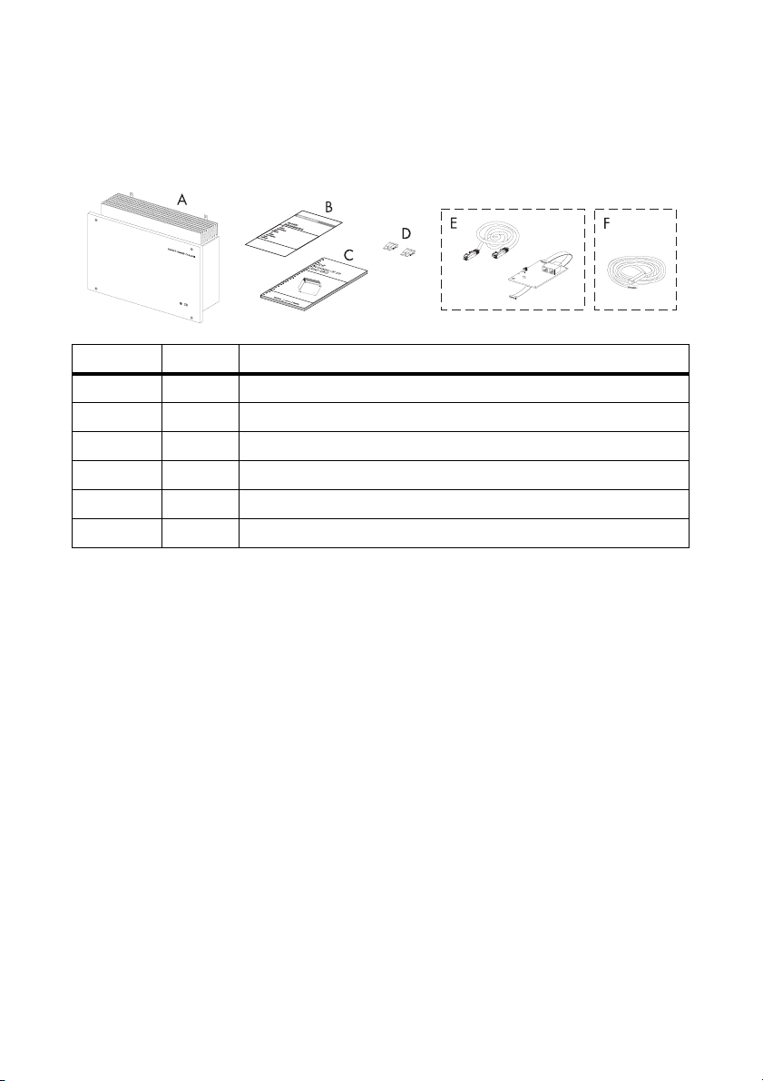
3.1 Packing List
Object Number Description
A 1 Charge controller
B 1 EC Declaration of Conformity
C 1 Technical description
D 2 Thermal fuse (30 A)
E (optional) 1 SIC-PB communication interface and RJ45 cable (5 m)
F (optional) 1 Battery temperature sensor
3.2 Checking for Transport Damage
Check the charge controller for visible external damage, such as cracks in the housing. Please
contact your dealer if you find any damage.
Technical Description SIC40-TEN081110 11
Unpacking SMA Solar Technology AG
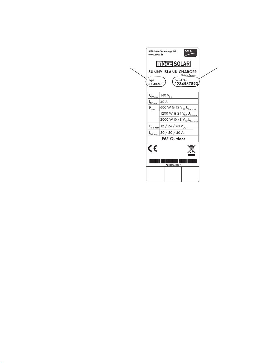
3.3 Identification of the Charge Controller
You can identify the charge controller by
the type label. The type label is on the right
side of the housing.
Device type
Series number
12 SIC40-TEN081110 Technical Description

SMA Solar Technology AG Mounting
4 Mounting
CAUTION!
Risk of injury due to the heavy weight of the charge controller.
• Take into account that the charge controller weighs 10 kg.
4.1 Selection of Mounting Location
DANGER!
Danger to life due to fire or explosion.
The charge controller housing can become hot during operation.
• Do not mount the charge controller on flammable construction materials.
• Do not mount the charge controller in areas where highly flammable materials are
stored.
• Do not mount the charge controller in areas where there is a risk of explosion!
CAUTION!
Danger of burn injuries due to hot housing parts.
• Mount the charge controller in such a way that it cannot be touched inadvertently
during operation.
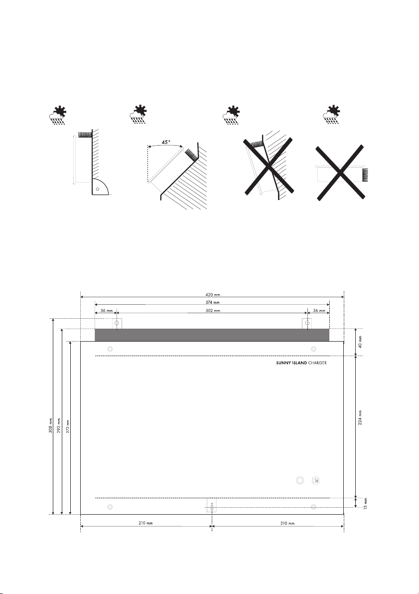
4.1.1 Dimensions
Technical Description SIC40-TEN081110 13
Mounting SMA Solar Technology AG
4.1.2 Ambient Conditions
• The mounting location and mounting method must be suitable for the weight and dimensions.
• Mounting on a solid surface.
• The mounting location must be accessible at all times.
• The charge controller must be easy to remove from the mounting location at any time.
• The ambient temperature should be between -25 °C and +60 °C to guarantee optimal
operation.
• Do not expose the charge controller to direct sunlight to avoid a power reduction due to
excessive heating.
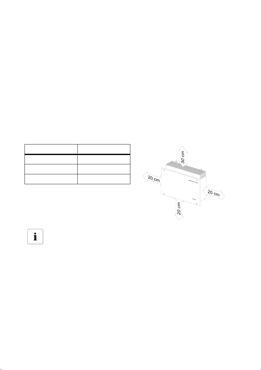
4.1.3 Safety Clearances
Observe the following safety clearances to walls, other devices or other objects to ensure sufficient
heat dissipation.
Direction Safety clearance
Sides 20 cm
Top 30 cm
Below 20 cm
,
Multiple charge controllers installed in areas with high ambient temperatures
If necessary, increase the clearances between the individual charge controllers, and
ensure that there is adequate ventilation to ensure sufficient cooling of the charge
controllers.
14 SIC40-TEN081110 Technical Description
SMA Solar Technology AG Mounting
4.1.4 Position
• Vertical installation or tilted backwards by max. 45 °.
• Install at eye level to allow operating modes to be read at all times.
• Never install the device with a forward tilt.
• Do not install horizontally.
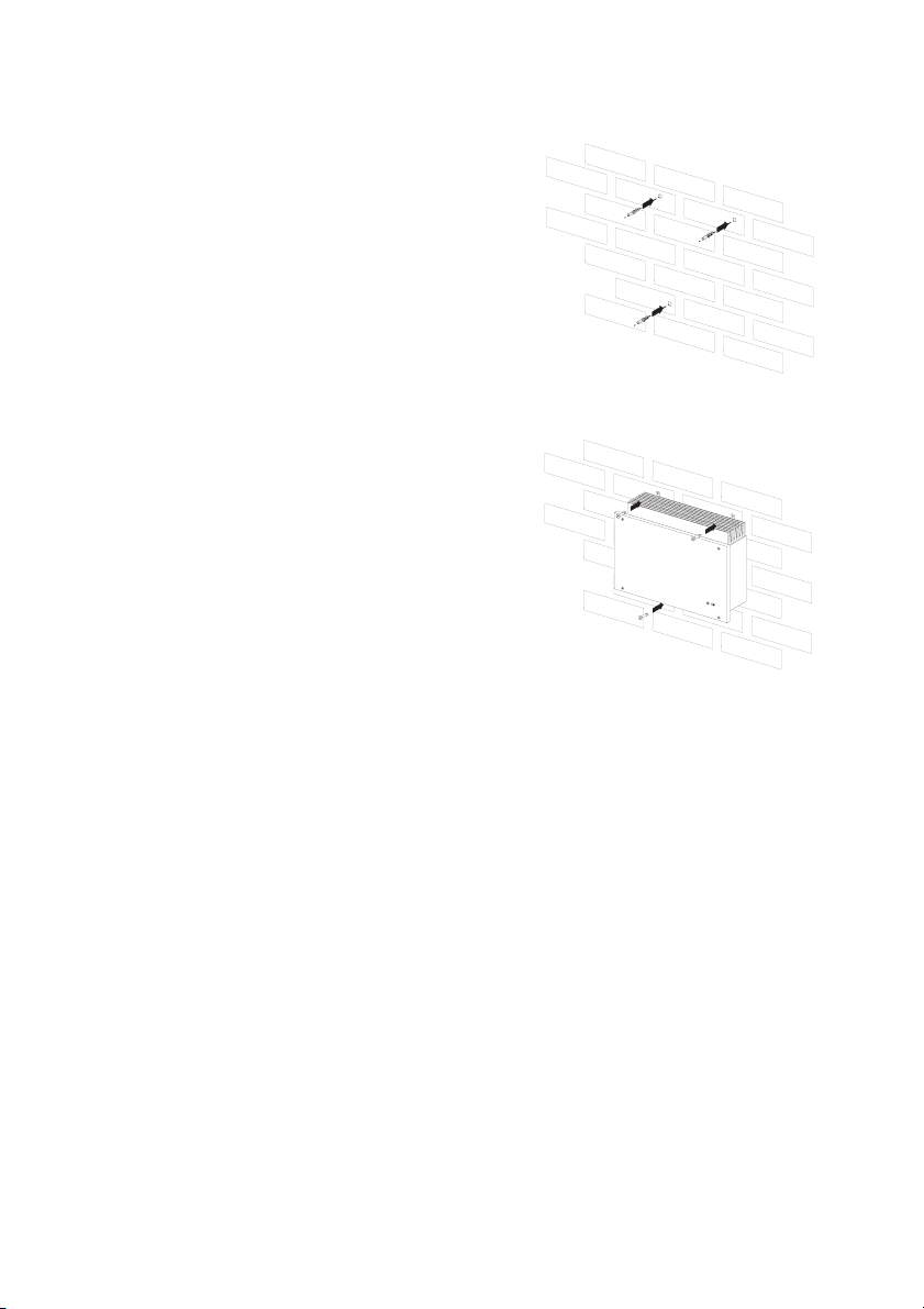
4.2 Mounting Instructions
1. Mark the positions of the drill holes.
Technical Description SIC40-TEN081110 15
Mounting SMA Solar Technology AG
2. Drill the holes (diameter: at least 8 mm) at the
marked positions and use wall anchors (at least
M8).
3. Screw the charge controller with its three mounting
plates on the wall. Use fastening material suitable
for the surface only.
S
U
N
N
Y
IS
L
A
N
D
CH
A
R
G
E
R
4. Check that the unit is securely in place.
16 SIC40-TEN081110 Technical Description
 Loading...