

SMA Sunny Island 4500 Installation & Operating Instructions Manual
Sunny Island 4500
Bi-directional Battery Inverter SI4500
for Stand-alone Applications
Installation & Operating Instructions


Sunny Island
Installation & Operating Instructions
Version 3.1
Bi-directional Battery Inverter SI4500
for Stand-alone Applications
BWRI45-13:EE0304

Sunny Island 4500 Installation & Operating Instructions
Alteration Review
Document
number
BWRI45
-13:EE5103 3.0 A,C Compilation and enhancement of SI3300
-13:EE0304 3.1 A Minor changes of layout Salisbury
Issue and type
of alteration
1
Comments Author
)
Sabban
documentation for SI4500
1
) A: Changes due to faulty documents or improvement of the documentation
B: Changes maintaining full or upward compatibility
C: Changes limiting or excluding compatibility
BWRI45-13-EE0304 - 2 - SMA Regelsysteme GmbH
Sunny Island 4500 Installation & Operating Instructions
Explanation of Symbols used in this Document
To enable optimal usage of this manual and safe operation of the device during in-
stallation, operation and maintenance routines, please note the following description
of symbols:
This indicates a feature that is important either for optimal and comfortable
usage or optimal operation of the system.
Example: “To keep string voltage low we recommend the following proce-
dure.”
This indicates a fact or feature which is very important for the safety of the
user and / or which can cause a serious defect if not applied appropriately.
Example: ”Disconnect the mains plug before opening the case!“
This indicates an example.
BWRI45-13-EE0304 - 3 - SMA Regelsysteme GmbH

Sunny Island 4500 Installation & Operating Instructions
Contents
1 Introduction........................................................................................................ 10
1.1 About these instructions............................................................................ 12
1.2 What to do in case of transport damages? ............................................... 12
1.3 General Safety Instructions....................................................................... 13
2 Device Description............................................................................................. 14
2.1 Operating Modes.......................................................................................15
2.1.1 Grid-Forming Operation (RUN_U)........................................................ 16
2.1.2 Grid-Tied Operation (RUN_I)................................................................ 18
2.1.3 Droop-mode operation (RUN_U, RUN_UEXT) ....................................19
2.1.4 Overload Behavior................................................................................ 21
2.2 Battery Management................................................................................. 23
2.2.1 Charging Methods ................................................................................ 24
2.2.2 Battery States ....................................................................................... 26
2.2.3 Low Battery Load Mode........................................................................ 29
2.2.4 Failure of Individual Cells .....................................................................30
3 Installation ......................................................................................................... 31
3.1 Mounting Accessories Included in Delivery...............................................31
3.2 Placement of the Sunny Island ................................................................. 33
3.3 Electric Connection ...................................................................................38
3.3.1 Preparing the Connection..................................................................... 38
3.3.2 Cable Connections ............................................................................... 40
3.4 Examples for Connection.......................................................................... 43
3.4.1 Connection to Ground ..........................................................................43
3.4.2 Connection of the battery .....................................................................45
3.4.3 Connection of Battery Temperature Sensor ......................................... 47
BWRI45-13-EE0304 - 4 - SMA Regelsysteme GmbH

Sunny Island 4500 Installation & Operating Instructions
3.4.4 Connection to AC Voltage .................................................................... 48
3.4.5 Connection measure Generator / Mains Current and Voltage .............49
3.4.6 Connection of a Generator ................................................................... 51
3.4.7 Connection to an External Utility ..........................................................53
3.4.8 Connection to Generator and Utility .....................................................56
3.4.9 Connection of a Battery Room Fan and Electrolyte Pump ................... 58
3.4.10 Connection of a Dump Load ............................................................. 60
3.4.11 Connection to “ecopower-Mini-BHKW” ............................................. 61
3.4.12 Connection to “ecopower-Mini-BHKW” and utility.............................62
3.5 Finalization of Electrical Wiring ................................................................. 63
3.6 Interfaces for Communication ...................................................................64
3.6.1 Assignment of COM1 Interface (Three-Phase Operation) ...................65
3.6.2 Assignment of COM2 Interface ............................................................66
3.7 Connection with Sunny Boy and Sunny Boy Control ................................ 67
3.7.1 Simple Connection at COM2 Interface ................................................. 67
3.7.2 Multiple Connection at COM2 Interface................................................ 69
3.7.3 Simple Connection to PC .....................................................................71
3.7.4 Alternative Communication at COM1 Interface .................................... 72
3.7.5 Assignment of COM3 Interface ............................................................73
3.8 Communication in a Three-Phase Island Grid ..........................................74
4 Operating Instructions ....................................................................................... 75
4.1 Display and Operating Elements...............................................................75
4.1.1 Key Assignment.................................................................................... 76
4.1.2 Contrast in Display ...............................................................................77
4.1.3 Return to Status Display....................................................................... 77
4.1.4 Edit Mode .............................................................................................78
4.2 Menu Structure..........................................................................................78
BWRI45-13-EE0304 - 5 - SMA Regelsysteme GmbH

Sunny Island 4500 Installation & Operating Instructions
5 First Commissioning of the Sunny Island .......................................................... 81
6 Configuration ..................................................................................................... 84
6.1 First Configuration..................................................................................... 85
6.1.1 “Master” or Single Sunny Island (“New Sys MASTER”) ....................... 85
6.1.2 “Slave” Sunny Island (“New Sys SLAVE”)............................................ 92
6.2 Configuration after Battery Exchange (“New Battery“).............................. 95
6.3 Configuration after Restart (“Restart”).......................................................98
7 Operation (OPERAT)......................................................................................... 99
7.1 Menu “START” (2-1), Operation of the Sunny Island.............................. 100
7.2 Menu “GENSET” (2-2), Operation of Generator ..................................... 101
7.3 Menu “FUNCT“ (2+3), Special Functions................................................ 104
7.4 Menu „BHKW“ (2+5), ecopower support................................................. 105
8 Settings (SETUP) ............................................................................................ 107
8.1 Menu “SETTIM“ (3-1), Setting the System Clock.................................... 108
8.2 Menu “PASSWD“ (3-2), Entry of Password ............................................ 109
8.3 Menu “PARSYS“ (3+3), Parameters System.......................................... 110
8.4 Menu “PARGRD“ (3+4), Parameters Grid .............................................. 112
8.5 Menu “PARBAT“ (3+5), Parameters Battery........................................... 114
8.6 Menu “PARGEN“ (3+6), Parameters Generator ..................................... 117
8.7 Menu “PARREL“ (3+7), Parameters Relays ........................................... 121
8.8 Menu “PARSB“ (3+8), Parameters Sunny Boy....................................... 128
8.9 Menu “PARALL“ (3+9), all Parameters ................................................... 130
9 Operating Data (DATA) ................................................................................... 131
9.1 Menu „DATAV“ (1-0), Overview of Measured Values .............................133
9.2 Menu “DATSYS“ (1-1), System Data ...................................................... 134
9.3 Menu “DATALL“ (1-2), Overall Plant Data .............................................. 134
9.4 Menu “DATBAT“ (1+3), Battery Data...................................................... 136
BWRI45-13-EE0304 - 6 - SMA Regelsysteme GmbH

Sunny Island 4500 Installation & Operating Instructions
9.5 Menu “DATGRD“ (1+4), Grid Data.......................................................... 138
10 Diagnosis (DIAG)............................................................................................. 140
10.1 Menu “ACKN“ (4-1), Error Confirmation.................................................. 142
10.2 Menu “HISTOR“ (4-2), Overall Protocol .................................................. 142
10.3 Menu “ERRHIS“ (4-3), Error Protocol .....................................................143
10.4 Menu “EVTHIS“ (4-4), State Protocol...................................................... 143
11 Island Grids – Examples.................................................................................. 144
11.1 Photovoltaically powered Island Grid ...................................................... 145
11.2 Photovoltaically powered Island Grid with Generator .............................150
11.3 Mains Backup System with Photovoltaics............................................... 154
11.4 Mains Backup System with Generator and PV ....................................... 157
11.5 Integrating CHP-Units ............................................................................. 161
11.6 Multiple Sunny Island Systems (w/ Data interchange)............................ 165
11.6.1 Single-Phase System...................................................................... 165
11.6.2 Three-Phase System ...................................................................... 169
11.7 Multiple Sunny Island Systems (w/o Data interchange).......................... 172
11.7.1 Single-Phase System...................................................................... 173
11.7.2 Three-Phase System ...................................................................... 173
11.7.3 Mixed Single/Three-Phase Systems...............................................174
12 Terminal Diagrams for Generator Options ...................................................... 175
12.1 Stationary Generators ............................................................................. 175
12.2 Temporarily connected Generators......................................................... 179
12.3 “ecopower Mini-BHKW”, CHP-units ........................................................ 181
13 Technical Data................................................................................................. 182
14 Servicing and Maintenance ............................................................................. 185
15 Warranty and Liability Regulations .................................................................. 188
16 Parameters (Overview).................................................................................... 190
BWRI45-13-EE0304 - 7 - SMA Regelsysteme GmbH

Sunny Island 4500 Installation & Operating Instructions
17 Measured Values Displayed (Overview) ......................................................... 211
18 Error and Status Signals.................................................................................. 217
18.1 Error Signals ...........................................................................................217
18.2 Status Signals (“Events“) ........................................................................219
19 Declaration of Conformity ................................................................................ 222
20 Contact ............................................................................................................ 223
21 List of Figures .................................................................................................. 224
22 List of Tables ................................................................................................... 228
BWRI45-13-EE0304 - 8 - SMA Regelsysteme GmbH

Sunny Island 4500 Installation & Operating Instructions
Important Safety Notice:
The Sunny Island inverter may only be opened, installed and ser-
viced by qualified personnel. The device can still be charged with
very high hazardous voltages even when disconnected. Please
closely follow all steps as described in this document when working
on the inverter. All safety instructions and all appropriate technical
and local regulations must be followed.
BWRI45-13-EE0304 - 9 - SMA Regelsysteme GmbH

Sunny Island 4500 Installation & Operating Instructions
1 Introduction
By purchasing a Sunny Island you have decided to use one of the most advanced
modular battery inverters.
The Sunny Island works as
• a high-quality sine wave AC source for 230 V, 50 or 60 Hz island grids with
sophisticated overload behavior
• a high-class battery charger that assures a maximum lifetime of the con-
nected lead storage battery by using highly sophisticated charging algorithms
and providing external signals in order to activate electrolyte pumps and even
battery room fans
• a controller providing a high level energy management, including loadman-
agement and interaction with power sources like generators or photovoltaic in-
verters
• a universal generator management system, with capability to start, pre-
heat, cool down etc. combustion engines and even to control dedicated CHPs
(Combined Heat and Power units)
• a modularly expandable unit that can be combined with other Sunny Islands
for higher power demands or for three-phase systems
Furthermore it provides a large number of valuable features like system data monitor-
ing, time dependent switching operations etc. and complies with the according Euro-
pean standards on EMC as certified in the CE declaration (see Chapter 19).
BWRI45-13-EE0304 - 10 - SMA Regelsysteme GmbH

Sunny Island 4500 Installation & Operating Instructions
In the following you will find the installation and operating instructions of the Sunny
Island1 battery inverter. Don’t worry about the size of the document, it is not neces-
sary to read everything at once. However, the general safety instructions described in
Chapter 1.3 have to be observed at any rate.
This is both installer’s guide and user manual, so it is used as reference for the com-
missioning and as guideline on how to use all functions of the inverter optimally.
1
Sunny, Sunny Family, Sunny Island and Sunny Boy are registered trademarks of SMA Regelsysteme
GmbH, Germany.
All other trademarks used in this documentation are the property of their respective owners and are
used herein for identification purposes only.
BWRI45-13-EE0304 - 11 - SMA Regelsysteme GmbH

Sunny Island 4500 Installation & Operating Instructions
1.1 About these instructions
This document contains important information for the installation and commissioning of
the Sunny Island as well as its safe operation. Please read these instructions carefully
before starting the inverter. The inverter must be installed and commissioned by quali-
fied personnel. Work must be carried out according to the local installation and safety
regulations. Please also refer to our warranty and liability terms at the end of this docu-
ment. This version of Installation and Operating Instructions considers the features for
the Sunny Island SI4500 with firmware BFR 2.00 / DSP 2.00, and higher.
1.2 What to do in case of transport damages?
Our products are thoroughly checked before they are shipped. Even though they are
delivered in sturdy packaging (which can be recycled) the inverters can be damaged
in transit which is usually the forwarder’s fault.
Please inspect your inverter thoroughly after it has been delivered. If any damages
can be detected on the packaging that could make you conclude the contents is
damaged or if you detect any damage please immediately notify the forwarding com-
pany.
SMA or your local supplier can help you in this matter. In any case a declaration of
transport damage must be made within six days upon receipt of the product and must
be stated in writing directly to the forwarding agent.
BWRI45-13-EE0304 - 12 - SMA Regelsysteme GmbH

Sunny Island 4500 Installation & Operating Instructions
1.3 General Safety Instructions
The Sunny Island is only suitable for installation in closed rooms.
Therefore do not expose it to humidity, rain or direct sunlight.
The inverter is designed for use in places up to 2000 m (6561 ft)
above sea-level.
Make sure there is sufficient air circulation in the battery room. Bat-
teries can develop an explosive atmospheres in normal operation.
Use specialized tools when mounting and wiring the storage battery
(risk of short circuit).
As a precaution against injuries wear suitable clothes for handling
heavy and bulky devices when mounting and removing the Sunny
Island (such as working gloves and safety shoes).
The device may only be opened, installed and serviced by a qualified
electrician. Even when disconnected there can be high touch volt-
ages within the device. Please see our detailed description of how to
handle the Sunny Island and closely follow all instructions!
Under certain circumstances the Sunny Island may start up autono-
mously! Keep this in mind when working on the island grid and al-
ways switch off the AC fuses of all Sunny Islands in the island grid!
BWRI45-13-EE0304 - 13 - SMA Regelsysteme GmbH

Sunny Island 4500 Installation & Operating Instructions
2 Device Description
As the central component of a modular power supply system the Sunny Island will
not only convert the energy to supply various kinds of electrical consumers or to
charge its batteries but also allow to connect the SMA Sunny Boy® String Inverters for
supplementary grid feeding. Furthermore, small wind energy converters or generator
sets and even Combined Heat and Power units (CHPs) are also supported.
To fulfill its tasks the Sunny Island can work in different operating modes. A short
overview is given in Chapter 2.1.
An outstanding feature of the Sunny Island is its capability to take care of the con-
nected lead storage battery. Highly sophisticated charging algorithms assure a
maximum lifetime of the battery. A quick abstract of the battery management is given
in Chapter 2.2.
Although the first commissioning of stand alone systems using the Sunny Island can
be kept very simple, it is just as well possible to fine-tune the system by a vast num-
ber of parameters (see Chapter 16) giving the users complete satisfaction.
Moreover, using this system-compatible battery inverter lets the planner / installer
reduce planning, execution and system costs for PV island supply considerably.
BWRI45-13-EE0304 - 14 - SMA Regelsysteme GmbH

Sunny Island 4500 Installation & Operating Instructions
2.1 Operating Modes
The Sunny Island can be modularly combined with other power sources and must
then operate in different operating modes. Depending on the system’s structure, the
Sunny Island can be configured to toggle automatically between these operating
modes. This chapter covers both basic grid configurations and the resulting require-
ments for the Sunny Island and the other components in the island grid.
Control of voltage and frequency in the island grid
Operation of the Sunny Island is based on the following operating modes:
• Grid forming (RUN_U), the Sunny Island keeps the voltage and the frequency of
the grid at a constant level.
• Grid-tied (RUN_I), the Sunny Island complies with the voltage and frequency
that is defined by an additional component of the island grid that itself forms the
grid.
• Droop-mode (special kind of RUN_U), the Sunny Island varies its battery cur-
rent depending on the grid’s frequency, and the grid’s voltage depending on its
current reactive power. It also tries to affect the grid’s frequency according to its
battery state. In case of being synchronized to a generator, the status
“RUN_UEXT” is shown in the display.
BWRI45-13-EE0304 - 15 - SMA Regelsysteme GmbH
Sunny Island 4500 Installation & Operating Instructions
2.1.1 Grid-Forming Operation (RUN_U)
In grid-forming mode the Sunny Island keeps the grid voltage at a constant sine-wave
voltage and constant frequency. The voltage and frequency is defined in the
“PARGRD“ 3+4 menu. The Sunny Island then has to provide the necessary active
and reactive power that is required for the control of the grid. All other components in
the grid then have to operate as grid-controlled power generators or consumers.
Consumers
230 V 50 Hz/60 Hz
Fig. 2.1: Sunny Island as grid-forming element
This operating mode requires that there are no further components within the grid
that control the frequency or the voltage. Parallel operation with the public utility or an
independent synchronous generator is not possible in this mode.
In this mode the Sunny Island can only charge the batteries whenever the compo-
nents within the grid (Sunny Boy inverters, synchronous generators) generate more
power than required. In case that these components generate less power than con-
sumed within the grid the Sunny Island supplies power to the grid by discharging the
batteries.
BWRI45-13-EE0304 - 16 - SMA Regelsysteme GmbH

Sunny Island 4500 Installation & Operating Instructions
The state of charge of the batteries can therefore only be manipulated by controlling
the power generating components and the consumers within the grid.
Due to the battery management, the Sunny Island can perform a full charge of high
quality even in this operating mode. This might take several days, if necessary (for
example if there are only photovoltaic feeders).
BWRI45-13-EE0304 - 17 - SMA Regelsysteme GmbH
Sunny Island 4500 Installation & Operating Instructions
2.1.2 Grid-Tied Operation (RUN_I)
In grid-tied operation the Sunny Island follows the voltage and frequency defined by
an external power source. This can be an independent synchronous generator or the
public utility. In this case, the Sunny Island does not control the grid voltage and grid
frequency but controls the current it draws from the grid to charge the battery in a
defined and most suitable manner.
Generator as
grid forming element
PV Modules
Control of
frequency
and voltage
SG
Consumers
Sunny Boy
Sunny Island
230 V 50 Hz/60 Hz
Control of battery
current and
battery voltage
Fig. 2.2: Sunny Island with external grid-former
BWRI45-13-EE0304 - 18 - SMA Regelsysteme GmbH
Sunny Island 4500 Installation & Operating Instructions
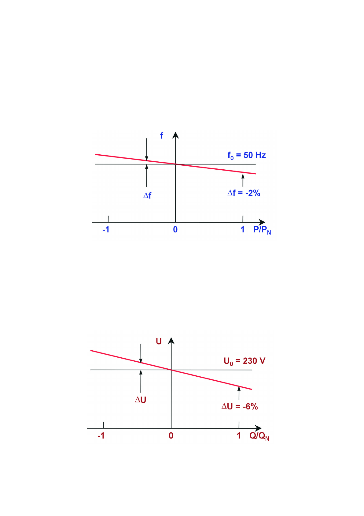
2.1.3 Droop-mode operation (RUN_U, RUN_UEXT)
The droop mode allows to connect several Sunny Islands (each provided with its own
battery) in parallel, even though each Sunny Island will act as a grid-forming device.
Such a system will behave in many respects similarly to the large public electric util-
ity:
Fig. 2.3: Frequency vs. load characteristics
If the available power on the AC bus of the system is higher than the power de-
manded, all Sunny Islands will charge their batteries and let the AC frequency slightly
rise, analog to the amount of energy stored in their batteries.
If the available power is less than the power demanded, the missing amount will be
fed into the AC bus by the Sunny Islands, slightly reducing the AC frequency.
Fig. 2.4: Voltage vs. reactive power characteristics
BWRI45-13-EE0304 - 19 - SMA Regelsysteme GmbH

Sunny Island 4500 Installation & Operating Instructions
Furthermore, the Sunny Island will respond to voltage fluctuations with reactive cur-
rent in droop mode. Thus, only an average cos φ of 1 will be reached. Temporarily, it
will deviate from this value.
In such systems further grid-forming elements (e.g. gensets) can only then be con-
nected if these are capable of automatically synchronizing themselves to the grid and
have a droop characteristic. However, for some common system structures the
Sunny Island provides functions to synchronize the system to the genset, even in
droop mode.
BWRI45-13-EE0304 - 20 - SMA Regelsysteme GmbH

Sunny Island 4500 Installation & Operating Instructions
2.1.4 Overload Behavior
One major feature of an island inverter is the performance in terms of overload. While
the consumers within the island grid will require an uninterrupted and continuous
power supply, the plant operators will want a long-term reliability and operation of the
inverter and the batteries as well. The manufacturer of the island inverter must take
into account fundamental aspects in terms of safety in order to provide maximum
safety for the personnel and the connected components.
Another reason for the careful observation of the overload performance is the con-
nection or activation of “problematic loads“. These are consumers that extract a very
high amount of power from the grid when they are activated. This power can be very
much higher than the nominal power, e. g. even simple halogen lamps extract the
fifteen-fold nominal power, when they are turned on.
These consumers do not continuously require this high power. Therefore, the Sunny
Island does not have to be capable of generating this power. What is more important
is a sophisticated control strategy. When such loads are connected, the Sunny Island
therefore reduces the AC voltage for a short time. This not only reduces the current
peaks on the AC side, but also those on the DC side – thus preserving the battery
power and prolonging the battery’s service life.
The overload capacity of the Sunny Island depends on all these requirements and
takes place in three stages:
In case that a short circuit is detected on the AC side, the output current is limited to
approx. 70 A
. If the short circuit persists for more than approx. 5 seconds, the
eff
Sunny Island 4500 switches off with an error message. This is enough in order to
trigger automatic circuit-breakers with A or R characteristics, respectively.
In case of a high overload, this is not yet detected as short circuit, the output active
power of the Sunny Island is limited by voltage decrease. Thus, the DC input current
BWRI45-13-EE0304 - 21 - SMA Regelsysteme GmbH

Sunny Island 4500 Installation & Operating Instructions
does not exceed approx. 125 A. The active power available at the output port there-
fore depends on the current battery voltage and is P = U
Bat
x I
x η.
Bat
This means, in case of battery voltage of 60 V it is approx. 7000 W. In case that the
load does not fall below this limit after a time of approx. 5 seconds, the Sunny Island
switches off with an error message. But all "problematic loads” should be able to
startup with this power.
In the overload area up to the limit mentioned above, the Sunny Island thermally lim-
its the power. This means, that the device – depending on the ambient temperature,
previous load and level of overload – can provide the power for several minutes or
even hours, before the device is derated or switched off. Another limiting element is
the DC-breaker F1 that might trip, also depending on the ambient temperature, previ-
ous load and level of overload.
However, even in the case, that permanently low ambient temperatures
are assumed, a plant should never be designed in a way that the Sunny
Island 4500 is continuously operated in overload operation. Otherwise, a
reduction of the durability of the device cannot be excluded.
BWRI45-13-EE0304 - 22 - SMA Regelsysteme GmbH
Sunny Island 4500 Installation & Operating Instructions
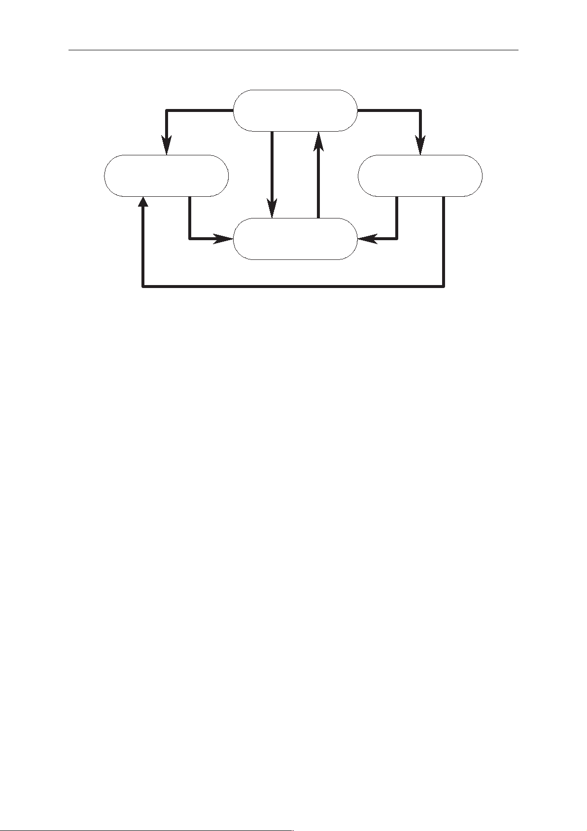
2.2 Battery Management
The battery management monitors the limit values for current, voltage and tempera-
ture, calculates the current state of charge and battery state, controls and monitors
the charge depending on the previous situations and can control an electrolyte circu-
lation pump as well as a battery room fan.
In order to have always reliable battery-related measured values, the Sunny Island
has to be the only device in the system that is connected to the battery directly.
External devices connected to the battery (e. g. DC loads or battery
chargers) will lead to a faulty battery management! This will not only
result in wrong battery states and associated erroneous switching op-
erations but also in an incorrect estimation of the battery’s condition
and thus to a significant reduction of the battery’s lifetime!
The associated parameters are described in Chapter 8.5.
All settings for the first operation are described in Chapters 6.1.1.
After having exchanged the lead storage battery of the system, restart
the Sunny Island(s) and follow the instructions in Chapter 6.2.
BWRI45-13-EE0304 - 23 - SMA Regelsysteme GmbH

Sunny Island 4500 Installation & Operating Instructions
2.2.1 Charging Methods
The battery is charged in a charging procedure adjusted to the type of battery (gel,
fleece or lead storage battery). The Sunny Island is informed of the battery type via
the parameter “502_Bat Type“ – e. g. in the menu “PARBAT“ (3+5). If you have in-
stalled a non VARLA battery with electrolyte circulation, please set the battery type to
gel battery as the charging voltages and times are more suitable for this type. The
final charge voltage of the battery is adjusted to the respective battery temperature,
which in turn has been determined via a battery temperature sensor. Above 20 °C the
reference value for the final charge voltage is therefore decreased by 4 mV/K (visible
in the menu “PARBAT“ (3+5)). Below 20 °C the value is increased accordingly.
The Sunny Island is capable of running four different charging methods. The different
voltage values and charging times of those methods are adjusted with temperature
compensation to the respective battery type that has been set via parameters. The
charging methods have been designated as follows:
• Normal charge (as often as possible)
• Full charge (at least once a month if possible)
• Equalizing charge (every two to three months)
• Float charge (after one of the other charging procedures has been completed)
Charging is initiated by the battery management, i. e. requested from the system
management when certain battery states have been reached.
BWRI45-13-EE0304 - 24 - SMA Regelsysteme GmbH
Sunny Island 4500 Installation & Operating Instructions
180 days or 30 charge throughputs
Equalizing charge
U = 2.45 V
Normal charge
U = 2.55 V
V > 2.5 V for 90 min
SOC 70%
Float charge
U = 2.23 V
180 days or 30 charge throughputs
14 days or 8 charge throughputs
Full charge
U = 2.5 V
U > 2.45V for 5 hU > 2.4V for 10 h
Fig. 2.5: Battery states with charging methods
The specified values are default values for a closed not circulated lead-acid battery.
A normal charge is made when the charging degree has fallen below 70 %. The pri-
ority is a short run-time of an additional aggregate (e. g. diesel generator).
By default, a full charge is completed every two weeks or 8 charge throughputs. A full
charge leads to complete charging of the battery in order to avoid irreversible aging
due to low charge degrees.
An equalizing charge is initiated every 180 days or 30 charge throughputs preventing
that the individual cells within the entire battery system over time have charge de-
grees differing among each other and avoiding aging of individual cells.
The respective charges are switched off according to the criteria for voltage, current
and time periods adjusted to the individual battery types.
BWRI45-13-EE0304 - 25 - SMA Regelsysteme GmbH
Sunny Island 4500 Installation & Operating Instructions
2.2.2 Battery States
The battery management determines the state of the battery out of a selection of
eleven possible battery states. It informs the relay control about the determined bat-
tery state. The most dominant input variable which is most important for the calcula-
tion of the battery state is the actual state of charge (see Fig. 2.6). This mainly pro-
vides information on the availability of the battery. In addition to the state of charge,
however, other variables mainly concerning battery aging are also used for calcula-
tion. These are e. g. the battery voltage during overcharging or exhaustive discharg-
ing, but also the times after a full charge or an equalizing charge has first been re-
quested. The battery state therefore shows that either the availability of the energy
stored deteriorates considerably due to the decreasing state of charge or the battery
is in an area with increasing aging while its state of charge can still be high.
battery low
Battery Requires
Charging!
0 %
Deactivate all
Consumers
battery
normal
40 %
50 % 60 %10 % 20 %
Start Battery Charging
With Generator
Partially deactivate
Consumers
100 %30 %
battery
overloaded
01 02 03N4 N3 N2 N1L1L2L3L4
Range
State of Charge
Battery State
Deactivate Wind Power Plant
Activate
Dumpload
Deactivate
Sunny Island
Fig. 2.6: Battery states, states of charge and suggested switching operations
BWRI45-13-EE0304 - 26 - SMA Regelsysteme GmbH
Sunny Island 4500 Installation & Operating Instructions
The battery states do not correspond as directly to the actual state of
charge as Fig. 2.6 suggests. Under certain circumstances the battery state
will remain stable even though the actual state of charge will vary widely.
It might even jump to a non contiguous state.
For example, in a new system the battery state will initially be set to L1
and will not change until a normal charge has been completed. After-
wards it will be set to N1 immediately.
Of course, in such cases all switching operations of the relays will be
executed as if the intermediate states were perambulated.
Battery states Description
L4, L3, L2, L1 Reduced availability of the battery and increased battery aging
N4, N3, N2, N1 Normal working area with varying availability of the battery
O1, O2, O3 Overload
Table 2.1: Classification of battery states
BWRI45-13-EE0304 - 27 - SMA Regelsysteme GmbH

Sunny Island 4500 Installation & Operating Instructions
The eleven defined battery states allow the user to make switches according to the
battery state. How to define battery state dependent switching operations is shown in
Chapter 8.7. The following table provides an overview of the different battery states
(BST), their meaning and recommendations for possible switching measures:
BST Meaning Recommendations Possible switching measures
O3
O2
O1
N1
N2
N3
N4
L1
Very high
overload
High
overload
Overload Decrease charging power Switch on dumpload
Very high security of supply
High security
of supply
Normal security of supply
Low security
of supply
Increasing aging
Immediately stop charging Switch off all feeders via the fre-
quency
Drastically decrease charging
power
None Switch off dumpload
Notification of state of charge; if
required first reduction of consumers
Either reduce consumption or
make sure battery is charged
soon
Either reduce consumption
drastically or make sure battery
is charged soon
Reduce consumption except for
emergency supply; initiate
charging, alarm message
Slight increase of frequency to
switch off first PV inverters
Switch off first load groups that are
not continuously used or reduction
of power
Switch on genset soon or switch
off certain load groups
Switch on genset also at night or
switch off all load groups that are
not urgently required
Switch on genset immediately or
switch off all load groups except
for emergency supply
L2
L3
L4
Strong aging Switch off all consumers, initi-
ate charging
Very strong
aging
Destruction of
battery imminent
Reduce internal consumption
immediately, initiate charging,
alarm message via switch-off
Immediately reduce internal
consumption, initiate charging,
alarm message via switch-off
Switch on genset immediately or
switch off all external load groups.
Low battery load mode will automatically be set at night.
Inverter into standby operation.
Low battery load mode will automatically be set day and night
Switch off the inverter
Sunny Island will go into standby
mode automatically
Table 2.2: Battery states and recommended measures
BWRI45-13-EE0304 - 28 - SMA Regelsysteme GmbH
 Loading...