

SMA Sunny Island 2012, Sunny Island 2224 Technical Description
Stand-alone grid inverter
Sunny Island 2012/2224
Technical Description
SI2012_2224-TEN082311 | 98-2005110 | Version 1.1
EN
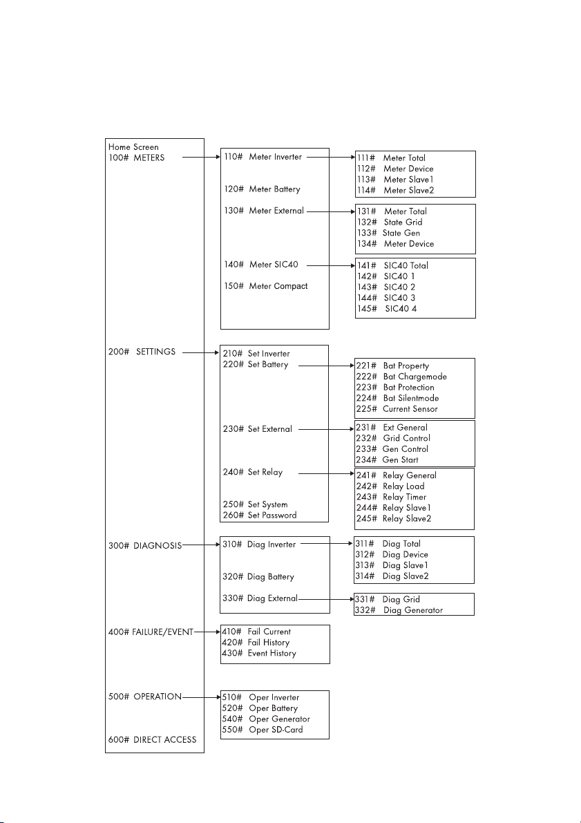
Overview of the menu area:
Main menu
Submenu 1
Submenu 2

SMA Solar Technology AG Table of Contents
Table of Contents
1 Notes on this Manual. . . . . . . . . . . . . . . . . . . . . . . . . . . . . . 9
1.1 Validity . . . . . . . . . . . . . . . . . . . . . . . . . . . . . . . . . . . . . . . . . . . . 9
1.2 Target Group . . . . . . . . . . . . . . . . . . . . . . . . . . . . . . . . . . . . . . 10
1.3 Storage of the Documentation . . . . . . . . . . . . . . . . . . . . . . . . . 10
1.4 Explanation of the Symbols Used . . . . . . . . . . . . . . . . . . . . . . 10
1.5 Syntax. . . . . . . . . . . . . . . . . . . . . . . . . . . . . . . . . . . . . . . . . . . . 11
2 System Overview. . . . . . . . . . . . . . . . . . . . . . . . . . . . . . . . 12
3 Safety Instructions . . . . . . . . . . . . . . . . . . . . . . . . . . . . . . . 16
4 Unpacking. . . . . . . . . . . . . . . . . . . . . . . . . . . . . . . . . . . . . . 17
4.1 Scope of delivery . . . . . . . . . . . . . . . . . . . . . . . . . . . . . . . . . . . 18
4.1.1 Sunny Island 2012/2224 . . . . . . . . . . . . . . . . . . . . . . . . . . . . . . . . . . . . . . 18
4.1.2 Sunny Remote Control 1 . . . . . . . . . . . . . . . . . . . . . . . . . . . . . . . . . . . . . . . 19
4.2 Name Plate/Firmware Version . . . . . . . . . . . . . . . . . . . . . . . . 20
4.2.1 Sunny Island 2012/2224 . . . . . . . . . . . . . . . . . . . . . . . . . . . . . . . . . . . . . . 20
4.2.2 Sunny Remote Control 1 . . . . . . . . . . . . . . . . . . . . . . . . . . . . . . . . . . . . . . . 21
5 Installation . . . . . . . . . . . . . . . . . . . . . . . . . . . . . . . . . . . . . 22
5.1 Required Tools and Resources. . . . . . . . . . . . . . . . . . . . . . . . . 22
5.2 Sunny Island 2012/2224. . . . . . . . . . . . . . . . . . . . . . . . . . . . 23
5.2.1 Dimensions . . . . . . . . . . . . . . . . . . . . . . . . . . . . . . . . . . . . . . . . . . . . . . . . . . 23
5.2.2 Choosing a Mounting Location . . . . . . . . . . . . . . . . . . . . . . . . . . . . . . . . . . 24
5.2.3 Observe minimum clearances . . . . . . . . . . . . . . . . . . . . . . . . . . . . . . . . . . . 25
5.2.4 Mounting Position. . . . . . . . . . . . . . . . . . . . . . . . . . . . . . . . . . . . . . . . . . . . . 26
5.2.5 Mounting the Sunny Island with a Wall Mounting Bracket. . . . . . . . . . . . . 27
5.3 Sunny Remote Control 1 . . . . . . . . . . . . . . . . . . . . . . . . . . . . . 31
5.3.1 Dimensions . . . . . . . . . . . . . . . . . . . . . . . . . . . . . . . . . . . . . . . . . . . . . . . . . . 31
5.3.2 Choosing a Mounting Location . . . . . . . . . . . . . . . . . . . . . . . . . . . . . . . . . . 31
5.3.3 Wall Mounting . . . . . . . . . . . . . . . . . . . . . . . . . . . . . . . . . . . . . . . . . . . . . . . 32
5.4 Installing Batteries. . . . . . . . . . . . . . . . . . . . . . . . . . . . . . . . . . . 33
Technical Description SI2012_2224-TEN082311 3

Table of Contents SMA Solar Technology AG
6 Opening and Closing. . . . . . . . . . . . . . . . . . . . . . . . . . . . . 36
6.1 Opening the Sunny Island . . . . . . . . . . . . . . . . . . . . . . . . . . . . 37
6.2 Closing the Sunny Island . . . . . . . . . . . . . . . . . . . . . . . . . . . . . 38
7 Sunny Island Electrical Connection. . . . . . . . . . . . . . . . . . 39
7.1 At a Glance . . . . . . . . . . . . . . . . . . . . . . . . . . . . . . . . . . . . . . . 40
7.2 DC connection . . . . . . . . . . . . . . . . . . . . . . . . . . . . . . . . . . . . . 43
7.2.1 Grounding . . . . . . . . . . . . . . . . . . . . . . . . . . . . . . . . . . . . . . . . . . . . . . . . . . 43
7.2.2 Connecting the Battery. . . . . . . . . . . . . . . . . . . . . . . . . . . . . . . . . . . . . . . . . 44
7.2.3 Connecting the Sunny Island . . . . . . . . . . . . . . . . . . . . . . . . . . . . . . . . . . . . 45
7.3 AC Connection. . . . . . . . . . . . . . . . . . . . . . . . . . . . . . . . . . . . . 46
7.3.1 Grounding . . . . . . . . . . . . . . . . . . . . . . . . . . . . . . . . . . . . . . . . . . . . . . . . . . 47
7.3.2 AC1 (Loads/Sunny Boys) . . . . . . . . . . . . . . . . . . . . . . . . . . . . . . . . . . . . . . 48
7.3.3 AC2 (Gen/Grid) . . . . . . . . . . . . . . . . . . . . . . . . . . . . . . . . . . . . . . . . . . . . . 50
7.4 Sunny Remote Control 1 . . . . . . . . . . . . . . . . . . . . . . . . . . . . . 51
7.5 Communication . . . . . . . . . . . . . . . . . . . . . . . . . . . . . . . . . . . . 53
7.5.1 Communication with Sunny Island . . . . . . . . . . . . . . . . . . . . . . . . . . . . . . . . 53
7.5.2 Communication With External Devices . . . . . . . . . . . . . . . . . . . . . . . . . . . . 56
7.6 Additional Connections . . . . . . . . . . . . . . . . . . . . . . . . . . . . . . 59
7.6.1 Battery Temperature Sensor . . . . . . . . . . . . . . . . . . . . . . . . . . . . . . . . . . . . . 59
7.6.2 Battery Current Sensor . . . . . . . . . . . . . . . . . . . . . . . . . . . . . . . . . . . . . . . . . 61
7.6.3 Multi-function Relays 1 and 2 . . . . . . . . . . . . . . . . . . . . . . . . . . . . . . . . . . . 63
7.6.4 BatVtgOut Power Supply . . . . . . . . . . . . . . . . . . . . . . . . . . . . . . . . . . . . . . . 66
7.6.5 DigIn Digital Input. . . . . . . . . . . . . . . . . . . . . . . . . . . . . . . . . . . . . . . . . . . . . 66
7.7 Configuring a System with Several Sunny Islands. . . . . . . . . . 68
7.8 Concluding Tasks . . . . . . . . . . . . . . . . . . . . . . . . . . . . . . . . . . . 69
8 Control Elements . . . . . . . . . . . . . . . . . . . . . . . . . . . . . . . . 70
8.1 Sunny Island. . . . . . . . . . . . . . . . . . . . . . . . . . . . . . . . . . . . . . . 70
8.1.1 Control Panel on the Enclosure . . . . . . . . . . . . . . . . . . . . . . . . . . . . . . . . . . 70
8.1.2 Control Panel Buttons . . . . . . . . . . . . . . . . . . . . . . . . . . . . . . . . . . . . . . . . . . 70
8.1.3 Meaning of the Light-Emitting Diodes (LEDs) . . . . . . . . . . . . . . . . . . . . . . . . 70
8.2 Sunny Remote Control 1 . . . . . . . . . . . . . . . . . . . . . . . . . . . . . 72
4 SI2012_2224-TEN082311 Technical Description

SMA Solar Technology AG Table of Contents
8.2.1 Display Messages . . . . . . . . . . . . . . . . . . . . . . . . . . . . . . . . . . . . . . . . . . . . 73
8.2.2 Key . . . . . . . . . . . . . . . . . . . . . . . . . . . . . . . . . . . . . . . . . . . . . . . . . . . . . . . . 73
8.2.3 Rotating Pushbutton . . . . . . . . . . . . . . . . . . . . . . . . . . . . . . . . . . . . . . . . . . . 74
8.2.4 MMC/SD card. . . . . . . . . . . . . . . . . . . . . . . . . . . . . . . . . . . . . . . . . . . . . . . 74
9 (First) Commissioning. . . . . . . . . . . . . . . . . . . . . . . . . . . . . 75
9.1 Requirements . . . . . . . . . . . . . . . . . . . . . . . . . . . . . . . . . . . . . . 75
9.2 Starting the Quick Configuration Guide (QCG) . . . . . . . . . . . 76
9.3 Commissioning the Battery Current Sensor . . . . . . . . . . . . . . . 81
10 Operating the Sunny Island . . . . . . . . . . . . . . . . . . . . . . . 83
10.1 Switching On and Off . . . . . . . . . . . . . . . . . . . . . . . . . . . . . . . 83
10.1.1 Switching On/Starting . . . . . . . . . . . . . . . . . . . . . . . . . . . . . . . . . . . . . . . . . 83
10.1.2 Stopping . . . . . . . . . . . . . . . . . . . . . . . . . . . . . . . . . . . . . . . . . . . . . . . . . . . . 85
10.1.3 Switching Off . . . . . . . . . . . . . . . . . . . . . . . . . . . . . . . . . . . . . . . . . . . . . . . . 87
10.1.4 Disconnecting the Device from Voltage Sources . . . . . . . . . . . . . . . . . . . . . 87
10.1.5 Restarting the System after Automatic Shutdown. . . . . . . . . . . . . . . . . . . . . 88
10.2 Navigation Area . . . . . . . . . . . . . . . . . . . . . . . . . . . . . . . . . . . 89
10.2.1 Standard View 1 . . . . . . . . . . . . . . . . . . . . . . . . . . . . . . . . . . . . . . . . . . . . . 92
10.2.2 Standard View 2 . . . . . . . . . . . . . . . . . . . . . . . . . . . . . . . . . . . . . . . . . . . . . 93
10.2.3 Select menu . . . . . . . . . . . . . . . . . . . . . . . . . . . . . . . . . . . . . . . . . . . . . . . . . 97
10.2.4 Selecting Parameters . . . . . . . . . . . . . . . . . . . . . . . . . . . . . . . . . . . . . . . . . . 99
10.2.5 Selecting Events . . . . . . . . . . . . . . . . . . . . . . . . . . . . . . . . . . . . . . . . . . . . . . 99
10.2.6 Selecting Warnings and Faults. . . . . . . . . . . . . . . . . . . . . . . . . . . . . . . . . . 100
10.3 Making adjustments . . . . . . . . . . . . . . . . . . . . . . . . . . . . . . . .101
10.3.1 Adjusting parameters . . . . . . . . . . . . . . . . . . . . . . . . . . . . . . . . . . . . . . . . . 101
10.3.2 Setting the Installer Password. . . . . . . . . . . . . . . . . . . . . . . . . . . . . . . . . . . 102
10.3.3 Accessing Parameters Directly . . . . . . . . . . . . . . . . . . . . . . . . . . . . . . . . . . 105
10.3.4 Meter Compact . . . . . . . . . . . . . . . . . . . . . . . . . . . . . . . . . . . . . . . . . . . . . 105
10.4 Saving Data onto a MMC/SD Card. . . . . . . . . . . . . . . . . . . 107
10.4.1 Inserting the Card. . . . . . . . . . . . . . . . . . . . . . . . . . . . . . . . . . . . . . . . . . . . 111
10.4.2 Removing the Card. . . . . . . . . . . . . . . . . . . . . . . . . . . . . . . . . . . . . . . . . . . 112
10.4.3 Loading and Saving Parameters . . . . . . . . . . . . . . . . . . . . . . . . . . . . . . . . 112
10.4.4 Writing Log Data . . . . . . . . . . . . . . . . . . . . . . . . . . . . . . . . . . . . . . . . . . . . 113
Technical Description SI2012_2224-TEN082311 5

Table of Contents SMA Solar Technology AG
10.4.5 Show Status . . . . . . . . . . . . . . . . . . . . . . . . . . . . . . . . . . . . . . . . . . . . . . . . 113
10.4.6 Updating Firmware. . . . . . . . . . . . . . . . . . . . . . . . . . . . . . . . . . . . . . . . . . . 114
11 Additional Functions . . . . . . . . . . . . . . . . . . . . . . . . . . . . 117
11.1 Load shedding . . . . . . . . . . . . . . . . . . . . . . . . . . . . . . . . . . . . 117
11.2 Sleep Mode . . . . . . . . . . . . . . . . . . . . . . . . . . . . . . . . . . . . . . 118
11.3 Search Mode . . . . . . . . . . . . . . . . . . . . . . . . . . . . . . . . . . . . . 118
11.4 Time-controlled Operation . . . . . . . . . . . . . . . . . . . . . . . . . . . 119
11.5 Overload and Short Circuit Behavior . . . . . . . . . . . . . . . . . . 119
11.6 Device Failure and Autostart . . . . . . . . . . . . . . . . . . . . . . . . . 119
12 Battery management . . . . . . . . . . . . . . . . . . . . . . . . . . . . 120
12.1 Battery temperature. . . . . . . . . . . . . . . . . . . . . . . . . . . . . . . . 120
12.2 Start Options . . . . . . . . . . . . . . . . . . . . . . . . . . . . . . . . . . . . . 121
12.3 Charge State/SOC and SOH . . . . . . . . . . . . . . . . . . . . . . . . 121
12.4 Charge Control . . . . . . . . . . . . . . . . . . . . . . . . . . . . . . . . . . .122
12.4.1 Boost Charge . . . . . . . . . . . . . . . . . . . . . . . . . . . . . . . . . . . . . . . . . . . . . . . 124
12.4.2 Full Charge . . . . . . . . . . . . . . . . . . . . . . . . . . . . . . . . . . . . . . . . . . . . . . . . . 124
12.4.3 Equalization Charge . . . . . . . . . . . . . . . . . . . . . . . . . . . . . . . . . . . . . . . . . 126
12.4.4 Manual Equalization Charge. . . . . . . . . . . . . . . . . . . . . . . . . . . . . . . . . . . 127
12.4.5 Silent Mode . . . . . . . . . . . . . . . . . . . . . . . . . . . . . . . . . . . . . . . . . . . . . . . . 127
12.5 Battery Preservation Mode . . . . . . . . . . . . . . . . . . . . . . . . . . 127
12.6 Battery Diagnostics. . . . . . . . . . . . . . . . . . . . . . . . . . . . . . . . . 129
13 Connecting External Sources . . . . . . . . . . . . . . . . . . . . . 130
13.1 Generator. . . . . . . . . . . . . . . . . . . . . . . . . . . . . . . . . . . . . . . . 130
13.1.1 Connecting Generator Connections in Parallel . . . . . . . . . . . . . . . . . . . . . 131
13.1.2 Generator Start Options. . . . . . . . . . . . . . . . . . . . . . . . . . . . . . . . . . . . . . . 131
13.1.3 Generator Operation . . . . . . . . . . . . . . . . . . . . . . . . . . . . . . . . . . . . . . . . . 135
13.1.4 Manual Generator Operation . . . . . . . . . . . . . . . . . . . . . . . . . . . . . . . . . . 135
13.1.5 Automatic Generator Operation . . . . . . . . . . . . . . . . . . . . . . . . . . . . . . . . 137
13.1.6 Limits and Power Adjustment . . . . . . . . . . . . . . . . . . . . . . . . . . . . . . . . . . . 141
13.1.7 Run Times . . . . . . . . . . . . . . . . . . . . . . . . . . . . . . . . . . . . . . . . . . . . . . . . . . 143
6 SI2012_2224-TEN082311 Technical Description

SMA Solar Technology AG Table of Contents
13.1.8 Operation Together With Sunny Boys . . . . . . . . . . . . . . . . . . . . . . . . . . . . 144
13.1.9 Stopping the Generator . . . . . . . . . . . . . . . . . . . . . . . . . . . . . . . . . . . . . . . 145
13.1.10 Failures . . . . . . . . . . . . . . . . . . . . . . . . . . . . . . . . . . . . . . . . . . . . . . . . . . . . 146
13.2 Grid . . . . . . . . . . . . . . . . . . . . . . . . . . . . . . . . . . . . . . . . . . . . 146
13.2.1 Conditions. . . . . . . . . . . . . . . . . . . . . . . . . . . . . . . . . . . . . . . . . . . . . . . . . . 147
13.2.2 Stand-Alone Grid Operation . . . . . . . . . . . . . . . . . . . . . . . . . . . . . . . . . . . 147
13.2.3 Grid Reconnection . . . . . . . . . . . . . . . . . . . . . . . . . . . . . . . . . . . . . . . . . . . 147
13.2.4 Grid Operation. . . . . . . . . . . . . . . . . . . . . . . . . . . . . . . . . . . . . . . . . . . . . . 148
13.2.5 Grid Failure. . . . . . . . . . . . . . . . . . . . . . . . . . . . . . . . . . . . . . . . . . . . . . . . . 149
13.2.6 Failures . . . . . . . . . . . . . . . . . . . . . . . . . . . . . . . . . . . . . . . . . . . . . . . . . . . . 149
13.2.7 Limits and Power Adjustment . . . . . . . . . . . . . . . . . . . . . . . . . . . . . . . . . . . 149
13.2.8 Operation Together With Sunny Boys . . . . . . . . . . . . . . . . . . . . . . . . . . . . 150
13.3 Generator and Grid. . . . . . . . . . . . . . . . . . . . . . . . . . . . . . . . 151
14 Relay . . . . . . . . . . . . . . . . . . . . . . . . . . . . . . . . . . . . . . . . . 152
15 Sunny Boy in the Island Grid System . . . . . . . . . . . . . . . 154
15.1 Setting the Stand-alone Grid Parameters. . . . . . . . . . . . . . . . 154
15.2 Frequency Shift Power Control (FSPC) . . . . . . . . . . . . . . . . .156
16 Maintenance and Care . . . . . . . . . . . . . . . . . . . . . . . . . . 158
16.1 Enclosure . . . . . . . . . . . . . . . . . . . . . . . . . . . . . . . . . . . . . . . . 158
16.2 The Sunny Island's Control Panel. . . . . . . . . . . . . . . . . . . . . . 158
16.3 Sunny Remote Control 1 . . . . . . . . . . . . . . . . . . . . . . . . . . . . 158
16.4 Functional Test . . . . . . . . . . . . . . . . . . . . . . . . . . . . . . . . . . . . 158
16.5 Battery . . . . . . . . . . . . . . . . . . . . . . . . . . . . . . . . . . . . . . . . . .159
16.6 Disposal . . . . . . . . . . . . . . . . . . . . . . . . . . . . . . . . . . . . . . . . . 159
17 Parameter List Overview. . . . . . . . . . . . . . . . . . . . . . . . . 160
17.1 Display Values . . . . . . . . . . . . . . . . . . . . . . . . . . . . . . . . . . . . 162
17.2 Adjustable System Parameters . . . . . . . . . . . . . . . . . . . . . . . . 166
17.3 Diagnosis . . . . . . . . . . . . . . . . . . . . . . . . . . . . . . . . . . . . . . . . 178
17.4 Events, Warnings and Failures (History) . . . . . . . . . . . . . . . . 182
Technical Description SI2012_2224-TEN082311 7

Table of Contents SMA Solar Technology AG
17.5 Functions During Operation. . . . . . . . . . . . . . . . . . . . . . . . . . 182
18 Troubleshooting/Problem Solving . . . . . . . . . . . . . . . . . 184
18.1 Error Confirmation . . . . . . . . . . . . . . . . . . . . . . . . . . . . . . . . . 184
18.2 Handling Autostart . . . . . . . . . . . . . . . . . . . . . . . . . . . . . . . . .184
18.3 Handling Failures Present During Startup . . . . . . . . . . . . . . . 184
18.4 Display of Failures and Events . . . . . . . . . . . . . . . . . . . . . . . . 184
18.5 Events . . . . . . . . . . . . . . . . . . . . . . . . . . . . . . . . . . . . . . . . . . . 185
18.6 Error Categories. . . . . . . . . . . . . . . . . . . . . . . . . . . . . . . . . . . 188
18.7 Warnings and Failure messages . . . . . . . . . . . . . . . . . . . . . . 188
18.8 Troubleshooting . . . . . . . . . . . . . . . . . . . . . . . . . . . . . . . . . . .192
19 Optional Devices . . . . . . . . . . . . . . . . . . . . . . . . . . . . . . . 195
19.1 External DC fuse. . . . . . . . . . . . . . . . . . . . . . . . . . . . . . . . . . . 195
19.2 External DC charge controllers (optional) . . . . . . . . . . . . . . . 195
19.3 Accessories (Optional). . . . . . . . . . . . . . . . . . . . . . . . . . . . . . 195
19.4 SMA Products (Optional). . . . . . . . . . . . . . . . . . . . . . . . . . . . 196
20 Technical Data . . . . . . . . . . . . . . . . . . . . . . . . . . . . . . . . . 197
20.1 Sunny Island 2012/2224. . . . . . . . . . . . . . . . . . . . . . . . . . . 197
20.2 Sunny Remote Control 1 . . . . . . . . . . . . . . . . . . . . . . . . . . . . 200
21 Contact . . . . . . . . . . . . . . . . . . . . . . . . . . . . . . . . . . . . . . . 201
22 Glossary . . . . . . . . . . . . . . . . . . . . . . . . . . . . . . . . . . . . . . 202
8 SI2012_2224-TEN082311 Technical Description

SMA Solar Technology AG Notes on this Manual
1 Notes on this Manual
This technical description explains the functioning, correct installation and operation of a standalone grid system. It describes the Sunny Island 2012 / 2224 inverter as well as the Sunny Remote
Control 1 display.
Information on the following topics can be found in the respectively labeled sections:
- Installation: Chapter 2 "System Overview" (Page 12)
- Commissioning: Chapter 8 "Control Elements" (Page 70)
- Functions: Chapter 11 "Additional Functions" (Page 117)
- Appendix: Chapter 16 "Maintenance and Care" (Page 158)
1.1 Validity
The technical description applies to the Sunny Island 2012 / 2224 firmware versions 2.0 and later
(see chapter 4.2 "Name Plate/Firmware Version" (Page 20)).
You can read the firmware version of your Sunny Island 2012 / 2224 on the display using the
"312.02 FwVer" parameter (see section 17.3 "Diagnosis" (Page 178)).
Information
The following applications are only possible with firmware versions 3.0 and above:
• Connection of two or three Sunny Island 2012 / 2224 devices to a 1-phase
parallel system
• Connection of two or three Sunny Island 2012 / 2224 devices to a 3-phase
parallel system
The stand-alone grid system devices may only be operated within the intended area of application
described in this documentation.
• The use of a stand-alone grid system to power life-sustaining medical devices is not permitted.
• The Sunny Reomet Control 1 is suited only for installation in enclosed spaces (protection rating
IP20).
• The Sunny Island 2012 / 2224 has been designed for use at elevations of up to 2600 m
above sea level. Please contact SMA Solar Technology AG before using the device at
elevations above 2600 m.
A performance loss of 0.5 % per every 100 m is to be expected starting at an elevation of
2000 m above sea level.
Technical Description SI2012_2224-TEN082311 9
Notes on this Manual SMA Solar Technology AG
Do not use the stand-alone grid system devices for purposes other than those indicated in this
technical description. Use of the devices for other purposes can void the warranty as well as
damage both the devices and the system.
For further questions, you can call the Sunny Island hotline at
• +49561 95 22 399
• E-Mail: SunnyIsland.Service@SMA.de.
1.2 Target Group
This technical description is meant both for the installer and the operator of the stand-alone grid
system. Some of the tasks described in this document must be performed only by qualified
electricians and are labeled accordingly with warnings.
1.3 Storage of the Documentation
The manuals for the stand-alone grid system and its installed components must be kept in the
immediate vicinity of the Sunny Island so as to be accessible at all times.
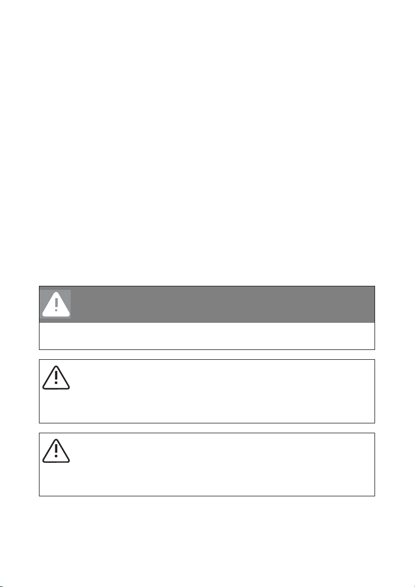
1.4 Explanation of the Symbols Used
The following types of safety warnings are used in this document:
DANGER!
"DANGER" indicates a hazardous situation which, if not avoided, will result in death or
serious injury.
WARNING!
"WARNING" indicates a hazardous situation which, if not avoided, could result in death
or serious injury.
CAUTION!
"CAUTION" indicates a hazardous situation which, if not avoided, could result in minor
or moderate injury.
10 SI2012_2224-TEN082311 Technical Description
SMA Solar Technology AG Notes on this Manual
Notice!
"NOTICE!" designates a safety warning about a condition which can lead to property
damage if the warning is ignored.
Information
"Notice" designates information which is important for the optimal operation of the
product.
1.5 Syntax
The syntax specified here for menus and parameters applies throughout the entire document:
Menu: Menu number, hash and menu name (150# Meter Compact)
Parameter:
Menu number, dot, parameter number and parameter name
(150.01 GdRmgTm)
Information
The parameter names used are based on the international IEC 61850-7-4 and
61400-25 standards.
Technical Description SI2012_2224-TEN082311 11
System Overview SMA Solar Technology AG
2 System Overview
The Sunny Island is a bi-directional battery inverter (battery inverter and charger) for off-grid
systems. The Sunny Island supplies consumers on the stand-alone grid side and charges battery
banks with the energy from grid-feeding units connected on the AC side.
High efficiency
The comfortable support of AC- and DC coupling as well as the expandability of the systems formed
with the Sunny Island guarantee highest flexibility. In addition, innovative technology allows the
Sunny Island to achieve a maximum efficiency of more than 93 %. Optimized for partial load
operation, its low open-circuit and standby consumption are convincing features. Because of its high
overload capability and integrated power management, overdimensioning of the Sunny Island is
not necessary.
Multiple Phase / Parallel Connection Capabilities
The parallel operation of up to three devices on a single phase of a battery or of three devices on
a three-phase system enables the Sunny Island to be used to set up stand-alone power supply
systems with outputs of up to 9 kW.
Automatic Generator Control
Thanks to its sophisticated generator management it can control connected diesel generators in a
particularly gentle and fuel-saving manner. It can also be integrated into the public grid. The Sunny
Island can also deactivate loads automatically if the battery does not provide sufficient electrical
energy.
Perfected Battery Management
The stand-alone grid's critical component, the battery, is monitored diligently and utilized optimally.
The intelligent battery management registers the battery's state of charge precisely. This makes
possible an improved utilization of the battery capacity, which means that smaller and thus more
cost-effective batteries can be used without affecting performance.
In order to prevent premature aging caused by incorrect charging and frequent deep discharge,
the Sunny Island has an intelligent charge control and reliable deep discharge protection. Because
of these functions the battery service life can be largely extended, in comparison with simpler
devices.
DC fuse
WARNING!
The Sunny Island 2012 / 2224 has no internal DC fuse.
Install an external DC fuse between the Sunny Island and the battery (see chapter 7.2
"DC connection" (Page 43)).
12 SI2012_2224-TEN082311 Technical Description

SMA Solar Technology AG System Overview
As an external DC fuse, the BatFuse secures the Sunny Island's battery connection leads.
In addition, the BatFuse allows the disconnection of the inverter on the DC side. You will find more
information in the technical description of the BatFuse. You can obtain the BatFuse as an accessory
from the SMA Solar Technology AG.
Simple Installation and Configuration
Despite the complex function of this battery inverter, the Sunny Island is easy to install and configure.
All the settings required for operation can be quickly and easily programmed in ten steps using the
"Quick Configuration Guide". Using the central operation concept referred to as "Single Point of
Operation", the system/cluster parameters are only set on the master device; all other devices adopt
the configuration automatically.
Menu Navigation and Data Archiving
The easy-to-understand menu navigation allows quick access to all important data, even while the
system is running. The Sunny Island can be controlled easily with the Sunny Remote Control 1
(SRC-1) external display. An MMC/SD card provides simple system supervision and thus simplifies
any service tasks.
Saving Data
Always use the MMC/SD card for saving data and events. This way, in case of a failure,
the SMA Solar Technology AG can help you quickly.
The Sunny Island monitors the set voltage and frequency limits on the grid and generator. If these
limits are not observed, it disconnects from the external source without interruption and changes to
stand-alone grid operation. The Sunny Island also has an integrated anti-islanding process in order
to prevent unintended islanding on the public grid. If this process is triggered, the system will also
change to stand-alone mode without any interruption.
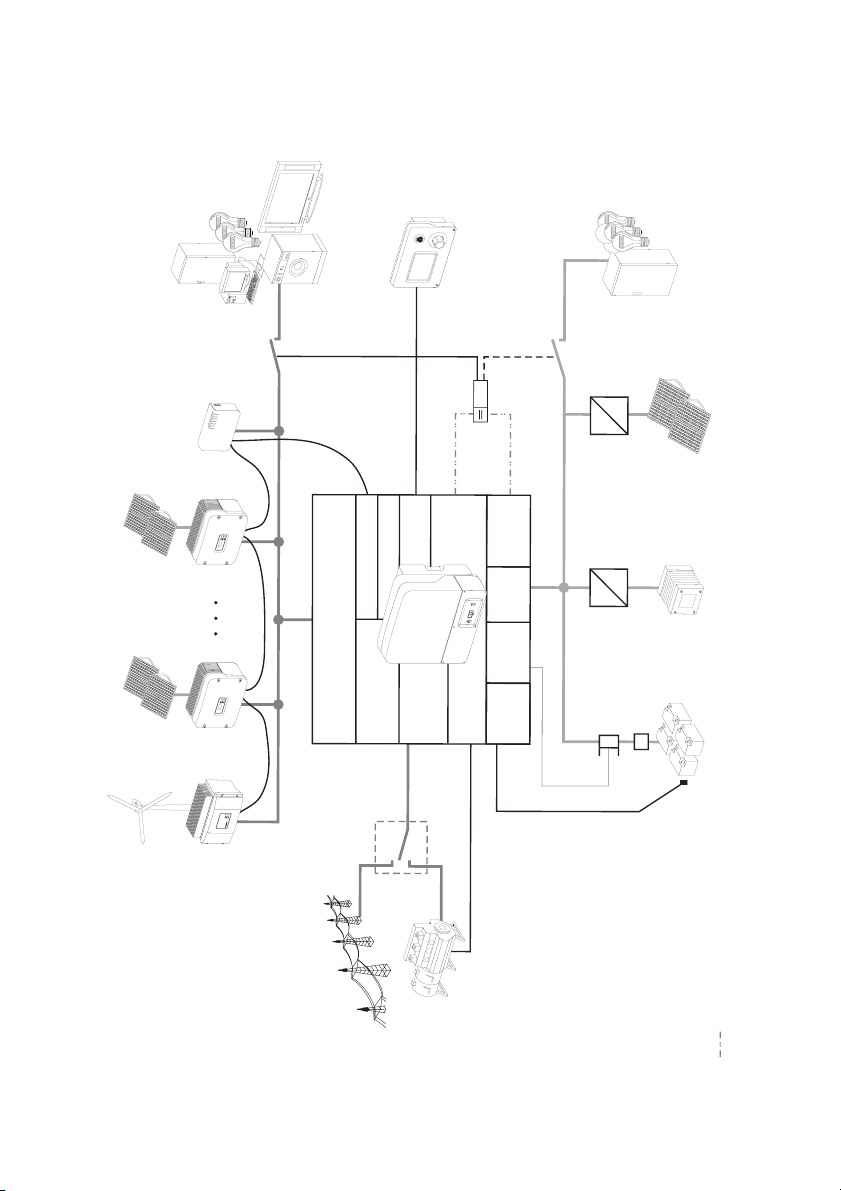
You can use the Sunny Island within various system configurations.
• The graphic on the following page shows which components can be integrated into a standalone grid system.
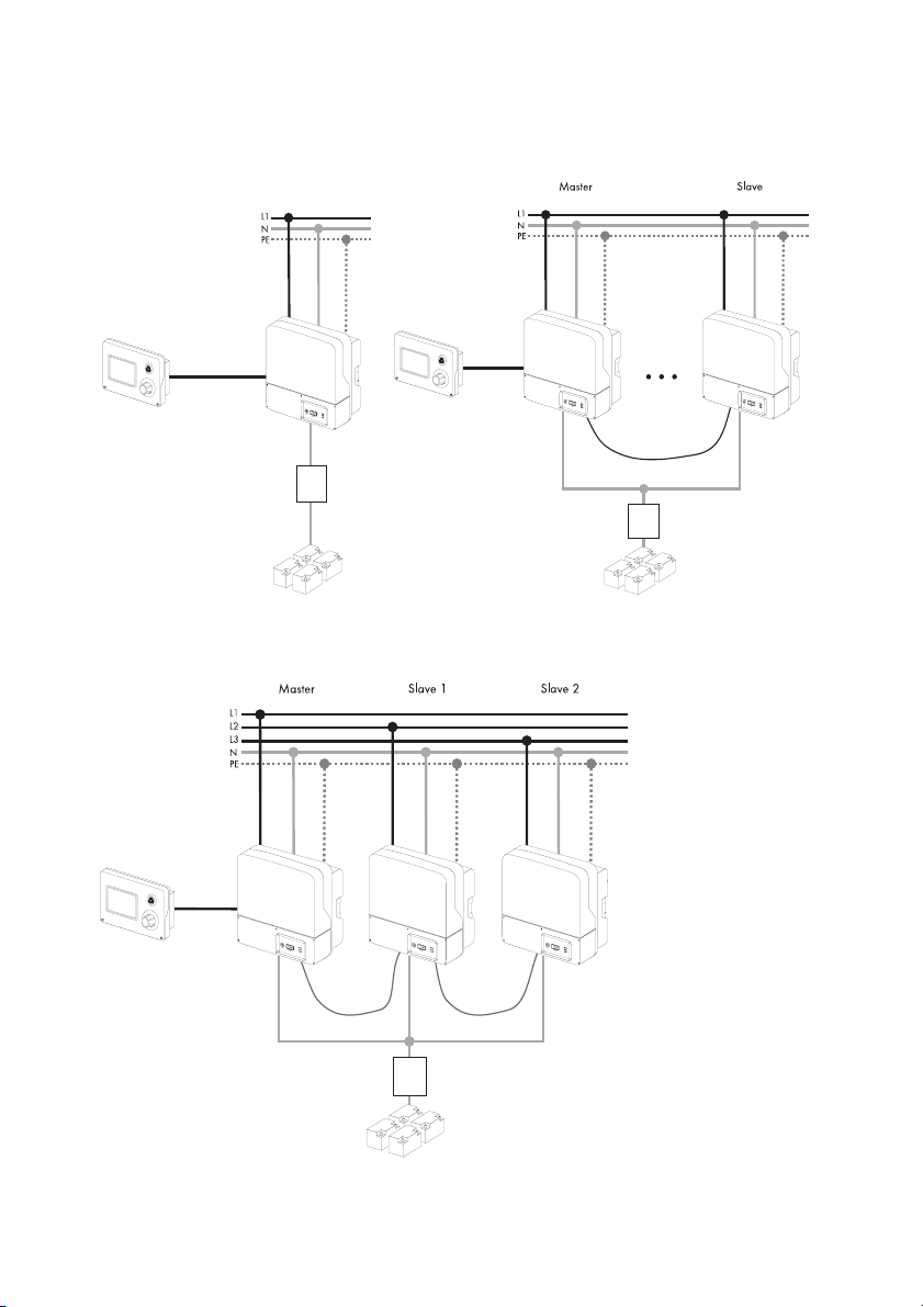
• The graphics on the page after next show the different wiring options (1-phase, 1-phase
parallel and 3-phase).
Technical Description SI2012_2224-TEN082311 13
System Overview SMA Solar Technology AG
DC-Loads
Loads
Sunny Remote Control 1
Charge
controller
POWER
SYSTEM
REPORT
MEMORY
SMACOM
NETCOM
USBCOM
Sunny
WebBox
*)
=
=
PV x
PV
Sunny Boy
Com IN
Com OUT
Display
Relay1/2
BatVtgOut
DC
DC/DC
Charger
=
=
Fuel Cell
BatCur
PV 1
AC1 (Loads/Sunny Boys)
Battery
DigIn
BatTmp
Relay1/2
AC2
(Gen/Grid)
current sensor
Battery
DC-Fuse
Windy Boy Sunny Boy
Battery
temperature sensor
Public grid
Generator
Control voltage
Description
14 SI2012_2224-TEN082311 Technical Description
*) DC-supply contactor (not included in delivery)
SMA Solar Technology AG System Overview
1-phasig 1-phasig parallel
3-phasig
Technical Description SI2012_2224-TEN082311 15
Safety Instructions SMA Solar Technology AG
3 Safety Instructions
Please follow all operating and safety instructions in this manual. Failure to follow these instructions
could result in damage to the device and personal hazard.
DANGER!
Risk of lethal electric shock when opening the devices.
• Installation and repair of the devices in the stand-alone grid system must be carried
out exclusively by qualified personnel.
• Observe all provisions and safety notices.
• Before starting work disconnect all live components by using circuit breakers.
• Secure circuit breakers against accidental switching on.
Information
Be sure to observe all applicable regional standards and guidelines.
16 SI2012_2224-TEN082311 Technical Description

SMA Solar Technology AG Unpacking
4 Unpacking
Before installing the Sunny Island and the Sunny Remote Control 1, make sure that all parts are
included in the delivery.
• Carefully check the packaging and the devices for any signs of damage.
• Ensure that all parts are included in the delivery (see section
4.1 "Scope of delivery" (Page 18)).
If something is missing or if the devices have been damaged during shipment, contact the SMA
Solar Technology AG immediately. Further information is provided in
section .21 "Contact" (Page 201).
Information
Keep the packaging in case you need to return the Sunny Island, the Sunny Remote
Control 1 or their accessories.
Technical Description SI2012_2224-TEN082311 17
Unpacking SMA Solar Technology AG
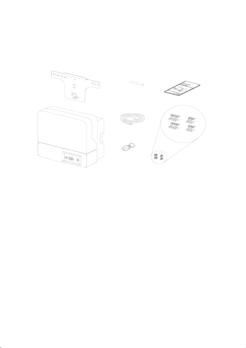
4.1 Scope of delivery
4.1.1 Sunny Island 2012/2224
The following elements are included:
G
F
B
A
C
H
A 1 Sunny Island 2012/2224 and lid.
B 1 Wall bracket
C 1 Battery temperature sensor
D 2 3-pin print terminals (for connecting relays 1 & 2)
E 2 4-pole print terminals for connecting battery temperature sensors
F 1 silicone tube 10 mm x 0.5 m
G 1 Technical Description (Manual)
H 1 M25 metric-thread cable screw
2x E
2x D
18 SI2012_2224-TEN082311 Technical Description
SMA Solar Technology AG Unpacking
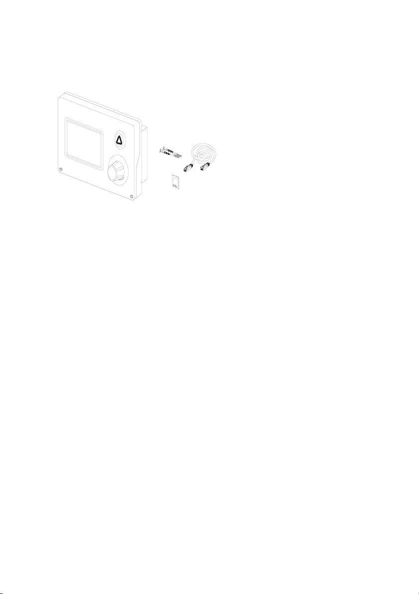
4.1.2 Sunny Remote Control 1
The following elements are included:
A
B
C
D
A 1 Sunny Remote Control 1 (SRC-1)
B 2 Screws and dowels
C 1 CAT5e-FTP patch cables (2 x RJ45 plugs, 5 m)
D1MMC/SD card
Technical Description SI2012_2224-TEN082311 19
Unpacking SMA Solar Technology AG
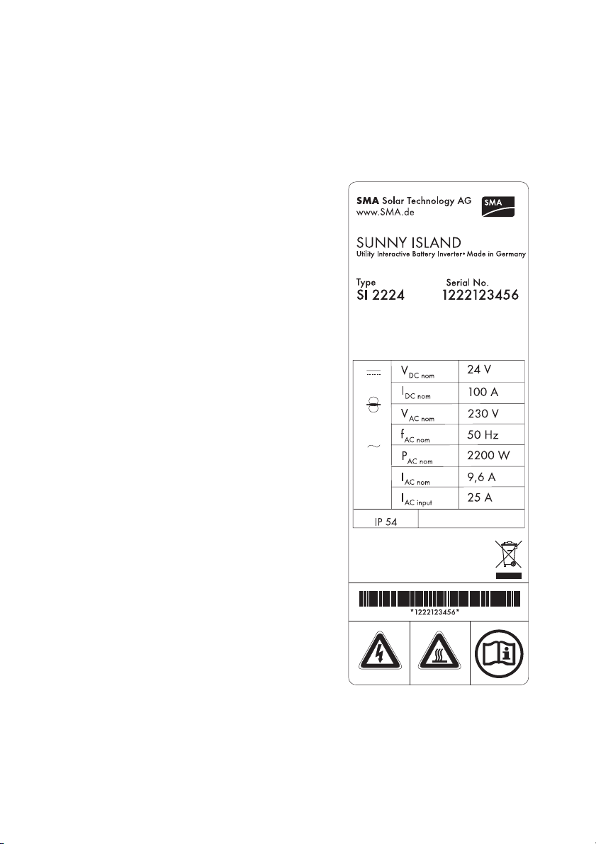
4.2 Name Plate/Firmware Version
4.2.1 Sunny Island 2012/2224
You can identify the Sunny Island by the type plate and firmware version. The following diagram
shows the type plate of the Sunny Island 2224.
• The name plate is located outside on the right side
of the housing.
• You can read the the firmware version of your
device on the display using the "331.02 FwVer"
parameter (see section
17.3 "Diagnosis" (Page 178).
20 SI2012_2224-TEN082311 Technical Description
SMA Solar Technology AG Unpacking
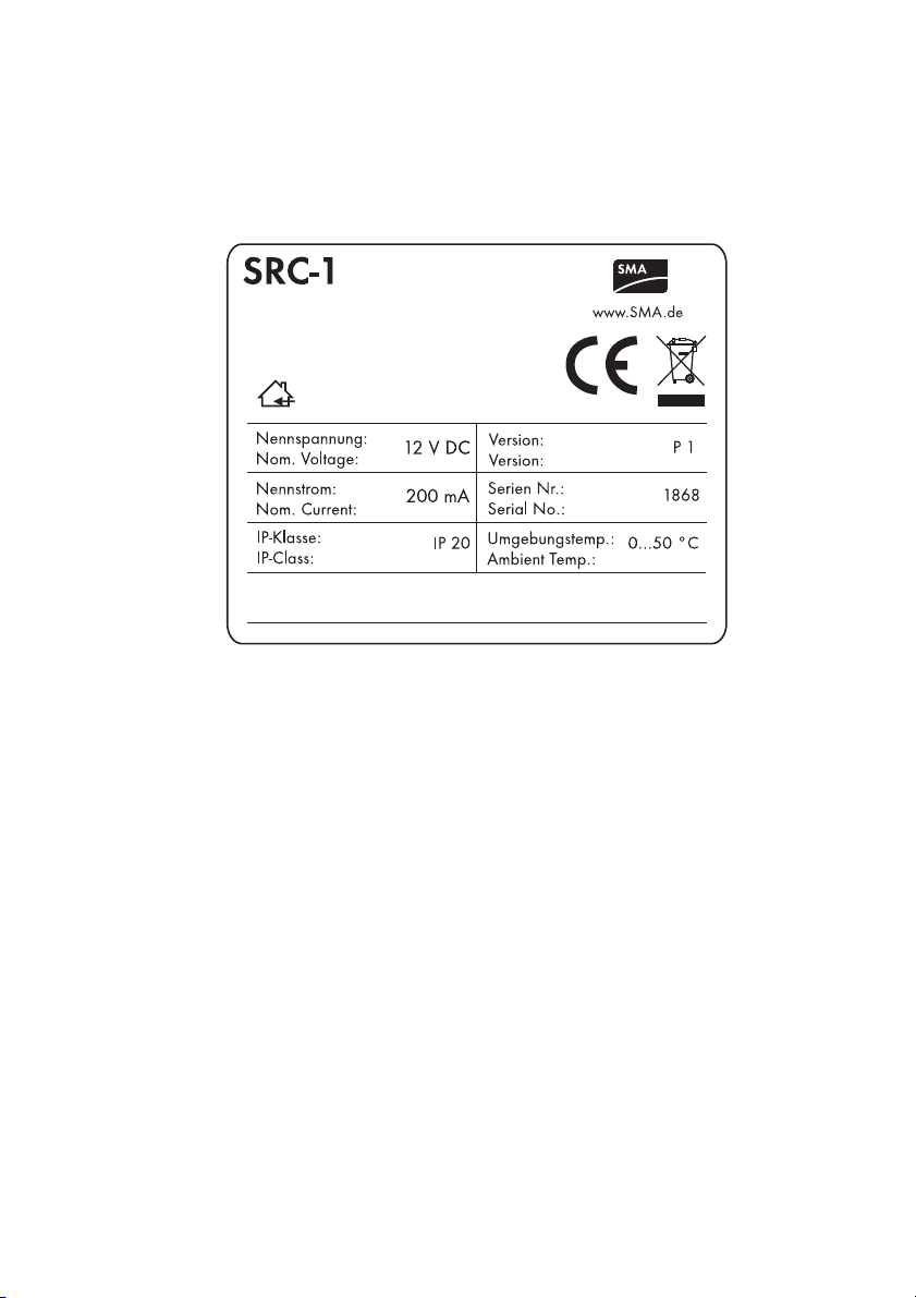
4.2.2 Sunny Remote Control 1
You can identify the display by the name plate. The type plate is located on the rear side of the
Sunny Remote Control 1.
.
Technical Description SI2012_2224-TEN082311 21

Installation SMA Solar Technology AG
5 Installation
Take note of the required installation conditions specified in the sections below before mounting,
installing and commissioning the Sunny Island.
5.1 Required Tools and Resources
The following tools and materials are recommended for mounting and installing the island grid
system:
Tools (not included in delivery)
Stripping pliers
Drill (e.g. stone drill), Ø 6 to 10 mm
Drill
Crimping tool for cable lug
Torque wrench (4 Nm to 10 Nm), 13 mm socket wrench
4 mm allen wrench
Cable knife
Ratchet (including extension)
Combination pliers
13 mm open end/ring wrench
Multimeter
Diagonal cutting pliers
Phillips screwdriver, PH1and PH2
Flathead screwdriver, 0.4 x 2.5 mm/1.0 x 10 mm/1.0 x 5.5 mm
Spirit level
Material (not included in delivery)
Cable end sleeves
Wall anchors for the wall bracket (e.g. SX 10)
Cable ties
AC cable (3 leads, 2.5 mm² each)
DC cable (95 mm² max.)
Cable lug for DC cable
hexagon bolts, 8x60 mm, washers
22 SI2012_2224-TEN082311 Technical Description
SMA Solar Technology AG Installation
Material (not included in delivery)
Heat shrink tubing
5.2 Sunny Island 2012/2224
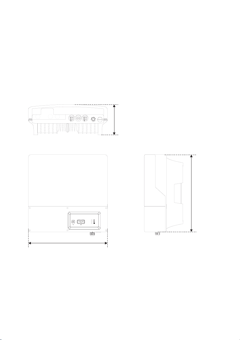
5.2.1 Dimensions
Housing:
185 mm
445 mm
470 mm
Technical Description SI2012_2224-TEN082311 23
Installation SMA Solar Technology AG
5.2.2 Choosing a Mounting Location
DANGER!
Death hazard due to fire or explosions
The temperature of the enclosure can reach 60 C during operation.
Do not install the device
• on flammable construction materials,
• in areas where highly flammable materials are stored,
• in potentially explosive areas
CAUTION!
Touching these parts could result in severe burns.
The temperature of the enclosure can reach 60 C during operation.
• Mount the device in such a way that it cannot be touched inadvertently!
• The location for the installation must be suitable for the weight (ca. 18 kg) and the size.
• Choose a solid fundament for mounting.
• The installation location must be accessible at all times (do not mount in inaccessible places).
• An ambient temperature of between -25 °C to +60 °C guarantees optimal operation.
• Avoid direct solar radiation. Excessive heating could lead to a reduction in performance.
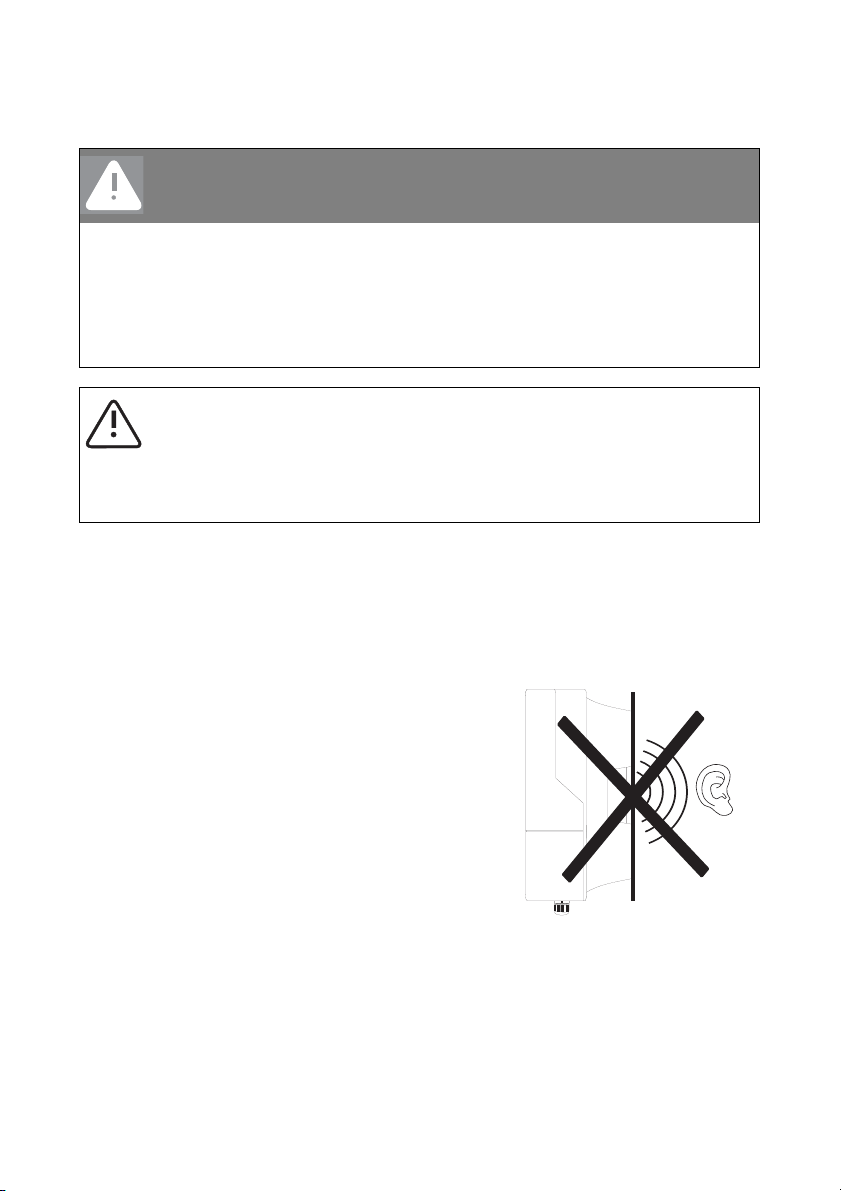
• In domestic installations, the unit should not be
mounted on plasterboard walls or similar materials in
order to avoid audible vibrations.
The Sunny Island can make noises when in use that
may be irritating in a domestic setting.
24 SI2012_2224-TEN082311 Technical Description
SMA Solar Technology AG Installation
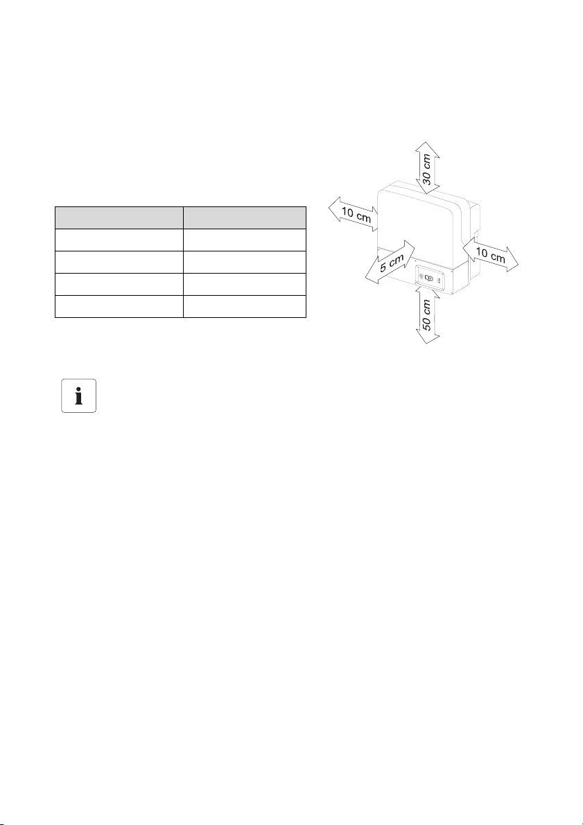
5.2.3 Observe minimum clearances
The following minimum clearances to walls, other devices or objects must be observed to guarantee
sufficient heat dissipation.
All external cables are connected through the
underside of the housing. This requires a minimum
clearance of at least 50 cm.
Direction Minimum clearance
sides 10 cm
above 30 cm
below 50 cm
in front 5 cm
Sufficient Ventilation
When installing the in smaller rooms, make sure that adequate ventilation is available.
During operation the device produces heat which must be dissipated.
Technical Description SI2012_2224-TEN082311 25
Installation SMA Solar Technology AG
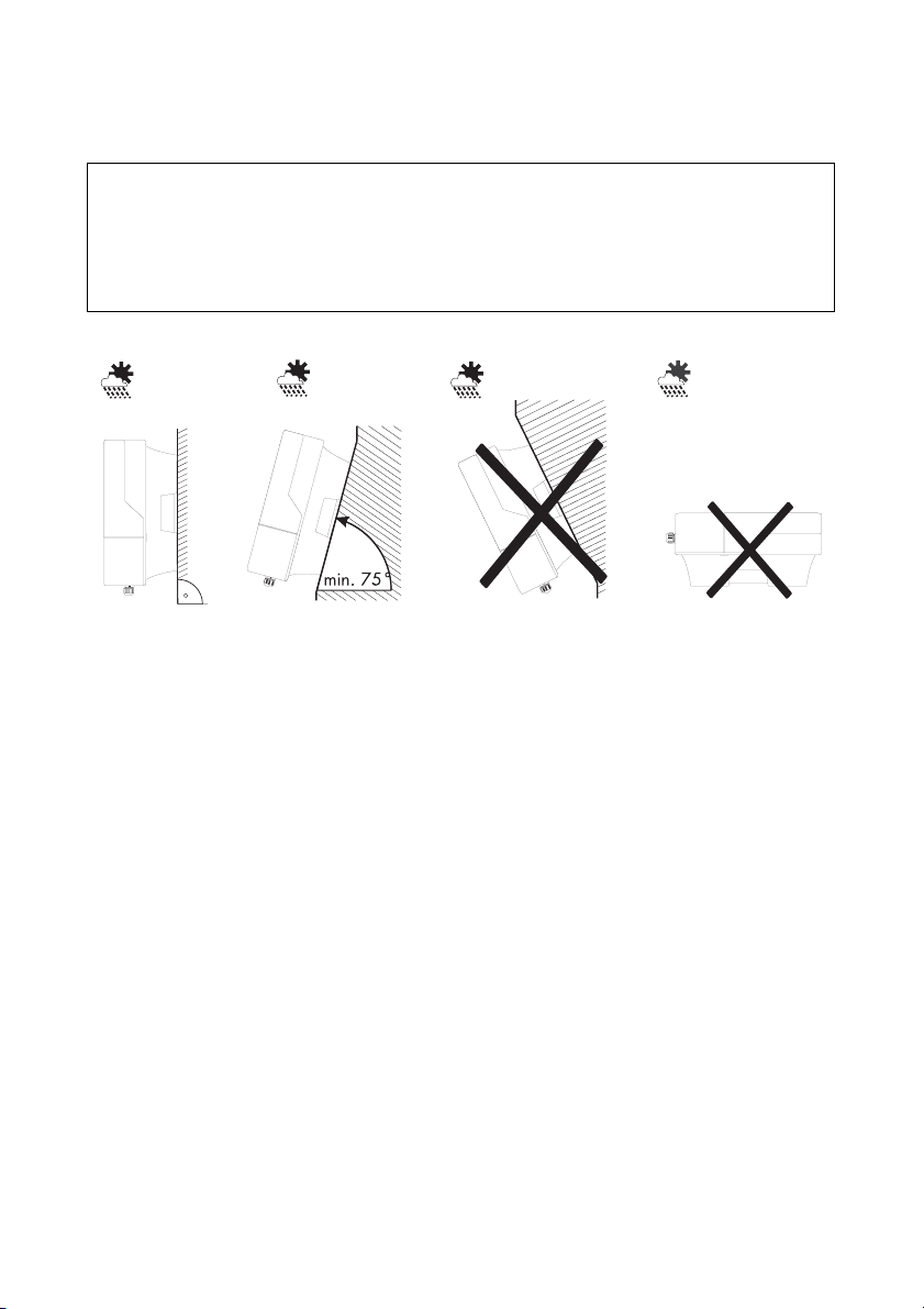
5.2.4 Mounting Position
NOTICE!
Short-circuit due to condensation
If the device is in operation while lying flat, water can accumulate due to condensation.
• Operate the device only while it hangs vertically on a wall.
• Mount the device only vertically or with a backward inclination of at most 15°!
• Do not mount the device with a forward inclination!
• Do not mount the device lying flat on its back!
• Mount the device at eye level.
26 SI2012_2224-TEN082311 Technical Description
SMA Solar Technology AG Installation
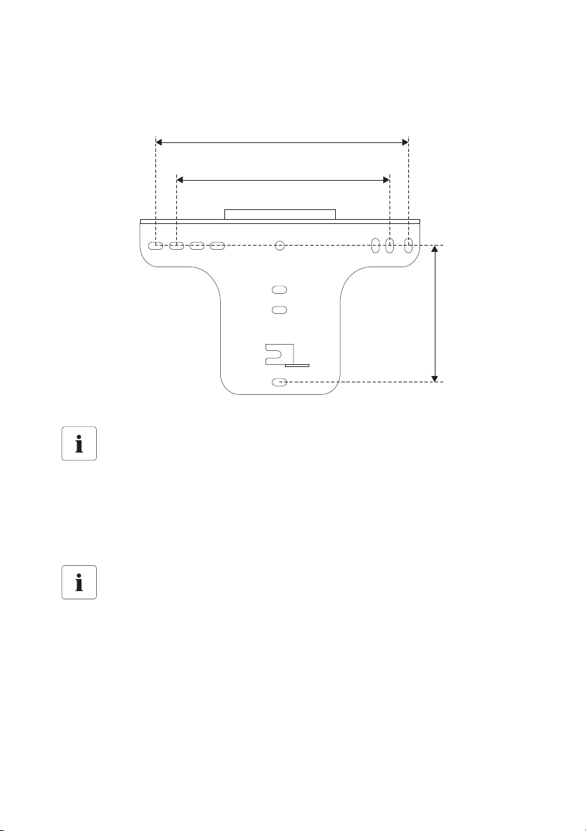
5.2.5 Mounting the Sunny Island with a Wall Mounting Bracket
1. Use the wall bracket as a drilling template.
.
315.9 mm
260 mm
170 mm
Number of drilled holes used
• When mounting onto a wall, use at least two of the horizontal holes and the lowest
one in the middle.
• When mounting onto a post use at least three of the holes in the middle (use the
superior one in any case).
Mounting Material
When mounting the wall bracket use mounting material which is suited to the fundament.
In doing this, observe that the weight of the Sunny Island is approximately 18 kg.
Technical Description SI2012_2224-TEN082311 27
Installation SMA Solar Technology AG
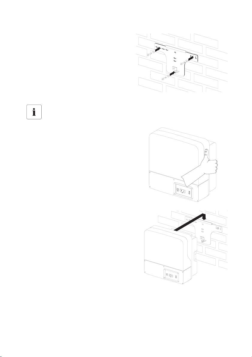
2. Mount the wall bracket.
Transporting the Sunny Central
For the transportation and the installation
of the Sunny Island use the handles at the
sides of its enclosure.
3. Hang the device onto the wall bracket with its
attachment plate somewhat displaced to the
left.
The right edge of the back side of the device
must be flush with the right edge of the wall
bracket.
28 SI2012_2224-TEN082311 Technical Description
SMA Solar Technology AG Installation
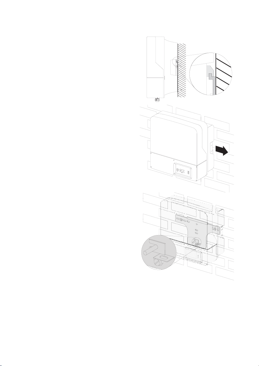
4. Check on both sides to see that the device sits
correctly.
5. Secure the enclosure so it cannot be
accidentally lifted up.
Shove the Sunny Island toward the right on the
wall bracket until it snaps into place with the
safety stud on its back side.
6. Check to see that the device sits correctly.
Technical Description SI2012_2224-TEN082311 29
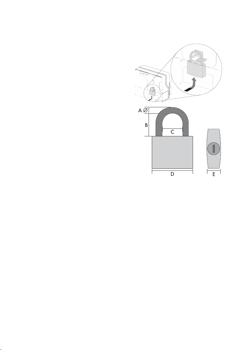
Installation SMA Solar Technology AG
Optional anti-theft protection
Protect the device against theft. Secure the Sunny
Island with a lock onto the wall mounting bracket.
The lock must meet the following specifications:
•Size:
A: 6 mm - 10 mm in diameter
B: 21 mm - 35 mm
C: 20 mm – 33 mm
D: 40 mm – 60 mm
E: 13 mm – 21 mm
•stainless
• hardened shackle
• secured cylinder lock
30 SI2012_2224-TEN082311 Technical Description
 Loading...