

SMA SUNNY HOME MANAGER 2.0,HM-20 Quick Reference Manual
HM-20-IS-en-10 | Version 1.0 SMA Solar Technology AG
SUNNY HOME MANAGER 2.0
Quick Reference Guide
Rev.0001
This document is valid for the Sunny Home Manager 2.0* ( HM-20) from firmware
version 2.00.00.R.
Only qualified persons with the following skills are allowed to perform the tasks described in this document:
• Training in the installation and commissioning of electrical devices and i nstalla-
tions
• Training in how to deal with the dangers and risks associated with installing and
using electrical devices and installations
• Knowledge of the applicable standards and directives
• Knowledge of and compliance with this document and all safety information
The Sunny Home Manager 2.0 is the central device responsible for energy management in households with a PV system for self-consumption.
The Sunny Home Manager 2.0 carries out the following basic tasks:
• Collection of energy- and power measured values in the interconnected household
• Energy monitoring: Presentation of energy flows via Sunny Portal
• Energy management: Automatic control of interconnected household loads wit h
the aim of energy efficiency optimization
• Dynamic limiting of the active power feed-in
• Active power measurement via integrated measuring unit with direct connection
up to 63 A limiting current
• Use of current transformers necessary for applications above 63A
• Interconnection of loads via EEBus and SEMP
• Support of the WLAN smart plugs Edimax SP-2101W
The Sunny Home Manager 2.0 does not support S0- or D0 energy meters, Plugwise products or Miele@home devices. The Sunny Home Manager 2.0 is not
equipped with a Bluetooth interface. The Sunny Home Manager 2.0 is not an en ergy meter for power consumption in the sense of the EU directive 2004/22/EG
(MID). The SunnyHomeManager 2.0 may not be used for billing purposes. The
data collected by the Sunny Home Manager 2.0 relating to the power generated
by your PV system may deviate from the data of the main energy meter, which is
used for billing purposes.
The Sunny Home Manager 2.0 may only be connected to the subdistribution of the
household on the load side behind the energy meter of the electric utility company.
The Sunny Home Manager 2.0 must be installed in a switch cabinet.
It is possible to use the Sunny Home Manager 2.0 in delta IT grids. When using the
Sunny Home Manager2.0 in delta IT grids, the cumulative power values are correctly measured. Due to the measuring principle of the Sunny Home Manager 2.0,
other measured values may be incorrect.
The Sunny Home Manager 2.0 is approved for use in all EU member states and
Australia. Only use the SunnyHome Manager 2.0 in accordance with the information provided in the enclosed documentation. Any other application may cause personal injury or property damage.
Alterations to the product, e.g. modifications or conversions, are only permitted with
the express written permission of SMA Solar Technology AG. Any use of the product other than that described in the Intended Use section does not qualify as appropriate.
The enclosed documentation is an integral part of the product and mu st b e re ad a nd
observed. Keep in a convenient place for future reference.
The type label must remain permanently attached to the product.
The latest version of this d ocument and the comprehensive manua
l for installation,
commissioning, configuration and decommissioning are to be found in PDF format
at www.SMA-Solar.com.
Links to additional information can be found at www.SMA-Solar.com:
This section contains safety information that must be observed at all times when
working on or with the product.
To pr event perso nal in jury and pr opert y dama ge and to ens ure lo ng-term operation
of the product, read this section carefully and observe all safety in formation at all
times.
• 1 x Sunny Home Manager 2.0 (HM-20)
• 1 x quick reference guide
Contact your specialist dealer if you find any damage.
Status LED ( ):
• Glowing green: Sunny Home Manager 2.0 is switched on.
• Flashing green: Firmware is being updated.
• Glowing red: Sunny Home Manager 2.0 is starting up.
• Flashing red: An error has occurred.
COM LED ( ):
• Off: No Ethernet connection established.
• Glowing green: Ethernet connection established.
• Flashing green: The Sunny Home Manager 2.0 is sending or receiving data.
Performance LED ( ):
• Off: No system registered in Sunny Portal.
• Flashing green: Energy management in the Sunny Home Manager 2.0 run-
ning smoothly.
• Flashing green: An error has occurred. The error has already been reported
to Sunny Portal.
• Glowing red: An error has occurred. The error has not yet been reported to
Sunny Portal.
• Flashing red: No connection to Sunny Portal established.
Refer to the "Troubleshooting" section for error diagnosis.
• Mount the SunnyHome Manager 2.0 on the top-hat rail. To do so, hook the
Sunny Home Manager 2.0 onto the top edge of the top-hat rail and press down
until it snaps into place.
☐ The Sunny Home Manager 2.0 is supplied with current via the line conductor
L1. At least the line conductor L1 and the neutral conductor must be connected
in order that the Sunny Home Manager 2.0 switches on.
☐ When using fine stranded wire, bootlace ferrules must be used.
☐ The screw terminals must be retightened after six to eight weeks.
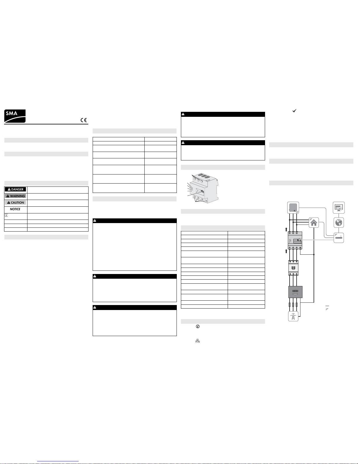
Installation using the integrated measuring unit
The following figure shows a connection example in TN and TT grid configurations
in the case of installation at the grid-connection point when using the integrated
measuring unit (recommended). For exact connection specifications, contact your
electric utility company.
Procedure:
1. Connect the conductors to the Sunny Home Manager 2.0. Observe the permitted connection cross-section and torque for screw terminals (see Section "Technical Data"):
• In a three-phase utility grid, connect the line conductors L1, L2 and L3 and
the neutral conductor to the Sunny Home Manager 2.0 in accordance with
the wiring diagram.
• In a single-phase utility grid, connect the line conductor L1 and the neutral
conductor to the Sunny Home Manager2.0 in accordance with the wiring
diagram.
VALIDITY
* Also referred to in this document as the product.
TARGET GROUP
SYMBOLS USED
Indicates a hazardous situation that, if not avoided, will result in death or serious injury.
Indicates a hazardous situation that, if not avoided, can result in death or serious injury.
Indicates a hazardous situation that, if not avoided, can result in minor or moderate injury.
Indicates a situation that, if not avoided, can result in property damage.
Information that is important for a specific topic or goal, but
is not safety-relevant.
☐ Indicates a requirement for meeting a specific goal.
☑ Desired result.
✖ A problem that might occur.
INTENDED USE
*()$+5
ADDITIONAL INFORMATION
Document title Document type
SUNNY HOME MANAGER 2.0 Operating manual
SMA SMART HOME - The System Solution for
more Independence
Planning guidelines
SMA SMART HOME - Home appliance energy
management using EEBus
Technical information
SMA SMART HOME - Battery Charging
Management with Time-of-Use Energy Tariffs
Technical information
SMA SMART HOME - Load Control via CAN
Time Period.
Example: Pool Pump
Technical information
SMASMART HOME - Load Control via MUST
Time Period.
Example: Washing Machine
Technical information
SMA SMART HOME Load Control Using
Relays or Contactors.
Example: Heating Rod
Technical information
SAFETY INFORMATION
DANGER
Danger to life due to electric shock
Lethal voltages are present in the live components.
• Disconnect the connection point from voltage sources and make sure it
cannot be reconnected.
• Before performing any work on the SunnyHome Manager 2.0, disconnect the grid side from all voltage sources using an install ed disconnect
switch.
• Ensure that the conductors to be connected are de-energized.
• On ly us e the S unny Hom e Ma nage r 2. 0 in a dry e nvir onme nt an d kee p
it away from moisture.
• Instal l the Sunny Home Man ager 2.0 in the switch c abinet only and ensure that the connection areas for the line conductors and the neutral
conductor are behind a cover or have contact protection.
• Disconnect the Sunny Home Manager 2.0 from voltage sources before
cleaning. The Energy Meter must be cleaned with a dry cloth only.
• Observe the prescribed minimum clearance between the network cable
and live installation components, or use suitable insulation.
DANGER
Danger to life due to electric shock if external disconnect switch is
missing
Lethal voltages are present in the live components of the
Sunny Home Manager 2.0.
•Install an external disconnect switch between the
Sunny Home Manager 2.0 and the grid-connection point. The external
disconnect switch must be close to the Sunny Home Manager 2.0 and
easily accessible.
WARNING
Danger to life due to electric shock
Overvoltages (e. g. in the case of a flash of lightning) can be further conducted into the building and to other c onnected devices in the same network via the network cable if there is no overvoltage protection.
• Ensu re that all de vices i n the sa me netw ork are integr ated in the existing
overvoltage protection.
• When laying the network cable outdoors, attention must be given to suitable overvoltage protection at the network cable transition outdoors to
the network inside the building.
WARNING
Risk of fire due to dirty or oxidized contact surfaces of live aluminum conductors
Connecting dirty or oxidized contact surfaces with aluminum conductors reduces the ampacity of the live terminals, thereby increasing the transition resistances. This can cause components to overheat and catch fire.
• The contact surfaces are to be cleaned, brushed, and treated with acidic
and alkaline substances (e.g. petroleum jelly or special thermal grease).
WARNING
Fire risk
If a fuse is mi ssin g or in corr ect a nd a f ault occu rs, a fire may be caused. This
can result in death or serious injury.
• Fuse the Sunny Home Manager 2.0 line conductor with a fuse or a selective circuit breaker with max. 63 A.
PRODUCT DESCRIPTION
SCOPE OF DELIVERY
TECHNICAL DATA
Communication Ethernet
Nominal voltage 230 V AC / 400 V AC
Frequency 50 Hz (± 5%)
Self-consumption < 3 W
Limiting current / line conductor 63 A
Connection cross-section with current trans-
formers
See recommendations of the current transformer manufacturer
Connection cross-section without current
transformers
10 mm² to 16 mm²
Max. cable length with current transformers 3 m
Torque for screw terminals 2 Nm
Weight 0.30 kg
Dimensions (W x H x D) 70 mm x 88 mm x 65 mm
Ambient temperature in operation -25°C to +40°C
Ambient temperature during transport/stor-
age
-25°C to +70°C
Relative humidity*
* non-condensing
5% to 90%
Maximum operating altitude above mean
sea level
2000 m
Protection class II
Degree of protection**
** in accordance with IEC 60529
IP2X
LED SIGNALS
L1
L2
L3
N
L1
L2
L3
SUNNY HOME MANAGER 2.0
Reset
B
A
C
D
E
A
F
A
B
C
E
F
: Connection area for line conductors
and neutral conductor
: Network terminal ( )
: Reset button
: COM LED
: Status LED
Ethernet
:D Performance LED
MOUNTING
INFORMATION ON CONNECTION AND COMMISSIONING
ELECTRICAL CONNECTION FOR APPLICATIONS UP TO 63 A
L1L2L3
N
SUNNY HOME MANAGER 2.0
L1 L2 L3
Reset
L1 L2 L3
NL1 L2 L3
L1 L2 L3
L1 L2 L3
N
Router/
Switch
Sunny
Portal
Internet
Household
Disconnect switch
Energy meter of
the electric
utility company
Main breaker
(three-phase)
OUT
IN
Utility grid
Inverters
Sunny Home
Manager 2.0
as
purchased electricity
and feed-in meter
L1 L2 L3
N
OUT
IN
, , : Line conductor
: Neutral conductor
: Meter output, load side
: Meter input, grid side
WLAN
Ethernet
HM-20-IS-en-10 SMA Solar Technology AG
Installation when not using the integrated measuring unit
If an SMA Energy Meter is installed at the grid-connection point and is not to be
replaced by the Sunny Home Manager 2.0, the Sunny Home Manager 2.0 can
also be operated without the measuring unit being enabled.
1. Connect the line conductor L1 and the neutral conductor to the voltage supply
of the Sunny Home Manager 2.0.
2. Select the SMA Energy Meter present as the purchased-electricity and feed-in
meter in Sunny Portal (see Section "Defining the Energy Meter at the Grid-Connection Point").
Measuring the PV production power (single-phase / three-phase) up to
63 A
In PV systems with inverters from other manufacturers or hybrid systems with SMA
inverters, the integrated measuring unit can also be used for measuring the PV production power. In this case there must already be an SMA Energy Meter installed
at the grid-connection point (see "Installation when not using the integrated measuring unit").
1. Connect the Sunny Home Manager 2.0 to the common connection point of all
inverters in the household grid.
2. Select the Sunny Home Manager 2.0 as the PV production meter in Sunny Portal (see Section "Defining the Energy Meter at the Grid-Connection Point").
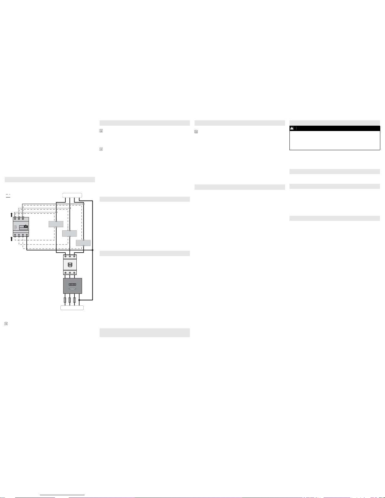
The following fig ure shows a connection exampl e in TN and TT grid configurations
in the case of installation at the grid-connection point. For exact connection specifications, contact your electric utility company.
Additionally required material (not included in the scope of delivery):
☐ 3 x current transformer
☐ Connection cables for current transformers
Procedure:
1. Connect one current transformer to each line conductor L1, L2 and L3.
2. On ea ch cu rren t tra nsfo rmer , con nect one c onne ctio n cab le fo r cur rent meas urement to each of the secondary current terminals (k/S1 and l/S2). Observe the
permitted connection cross-section of the
Sunny Home Manager 2.0
(see Sec-
tion "Technical Data"):
3. Connect the connection cables for current measurement (dashed gray line) to
the
Sunny Home Manager 2.0
. Observe the prescribed torque for screw termi-
nals (see Section "Technical Data").
4. Connect the connection cables for voltage measurement (solid gray line) to the
Sunny Home Manager 2.0
. Observe the prescribed torque for screw terminals
(see Section "Technical Data").
Connect the connection cables for voltage measurement to the corresponding line
conductors.
Additionally required material (not included in the scope of delivery):
☐ 1 x network cable
Recommended cable types:
• SF/UTP, S-FTP, S/UTP, SF/FTP, S/FTP, S-STP
Procedure:
1. Connect the network cable to the network terminal of the SunnyHomeManager
2.0.
2. Connect the other end of the network cable to a router / network switch.
Requirements:
☐ The PV system must be in operation.
☐ All devices must be in operation and connected to the
Sunny Home Manager 2.0 via a router / network switch.
☐ Devices that support the EEBus industry standard must be connected to the
Sunny Home Manager 2.0 (see technical information "SMA SMART HOME Home appliance energy management using EEBus").
☐ DHCP must be active for the router (see router manual).
Procedure:
1. Cover the Sunny Home Manager 2.0 with a cover or the contact protection of
the subdistribution.
2. Switch the power supply to the subdistribution back on.
☑ The LEDs on the Sunny Home Manager 2.0 light up during the startup proce
-
dure. All devices in the local network will be recognized autom atically.
3. Register all devices in Sunny Portal.
Sunny Portal serves as the user interface of the Sunny Home Manager 2.0. Therefore, you must register the Sunny Home Manager 2.0 in Sunny Portal.
Requirements:
☐ The PV sy stem and a ll de vice s in t he lo cal n etwo rk mu st be in operation (see Sec-
tion "Commissioning").
☐The registration ID (RID) and the identification key (PIC) from the
Sunny Home Manager 2.0 type label must be available.
Procedure:
1. Call up www.SunnyPortal.com and select [PV System Setup Assistant].
or
Call up www.SunnyPortal.com/Register.
☑ The PV System Setup Assistant opens.
2. Select [Next].
☑ The User Registration page opens.
3. Follow the instructions of the PV System Setup Assistant.
4. After completing the registration, configure further settings in Sunny Portal
(see the Sunny Home Manager 2.0 manual at www.SMA-Solar.com):
• Add automatically recognized devices
• Configure the load profile of the automatically recognized devices
• Enter the operator data
• Enter the PV array power
• Enter the feed-in tariff, self-consumption tariff and electricity tariff
• Configure settings for PV system monitoring.
Requirements:
☐ You must be logged in to Sunny Portal as an Installer.
Procedure:
1. Select Configuration > Device Overview in the page and menu selection.
2. In the Sunny Home Manager 2.0 row and the Properties column, select the
properties symbol.
3. Select [Edit].
4. In the Meter Configuration area, select the desired feed-in and purchased
electricity meter or PV production meter from the drop-down list (see Section
"Electrical Connection for Applications up to 63 A" for selection).
5. Select [Save].
Default settings
• To reset the Sunny Home Manager 2.0 to the default settings, press down and
hold the reset button using a sharp object for two to six seconds.
☑ LEDs flash first green and then red.
Restart
• To restart the Sunny Home Manager 2.0, press down and hold the reset button
using a sharp object for longer than six seconds.
☑ LEDs go out. The status LED then glows red constantly during system startup.
Pressing down and holding the reset button for less than two seconds has no effect.
The Sunny Home Manager 2.0 status LED flashes red.
It may be that DHCP has not been activated in the router.
• Activate DHCP in the router.
The Sunny Home Manager 2.0 performance LED flashes green.
An error has occurred. The error has already been reported to Sunny Portal.
• Ch eck the sys tem log boo k in the Sun ny Por tal sys tem and fol low the rec omm end ed actions.
The Sunny Home Manager 2.0 performance LED glows red.
An error has occurred. The error has not yet been reported to Sunny Portal.
• Ensure that the Sunny Home Manager 2.0 is connected to the Internet via the
local router. If the connection is correct, the error information will be transmit ted
to Sunny Portal.
• Ch eck the sys tem log boo k in the Sun ny Por tal sys tem and fol low the rec omm end ed actions.
The Sunny Home Manager 2.0 performance LED flashes red.
There is no connection to Sunny Portal.
• Ensure that the Sunny Home Manager 2.0 is connected to the Internet via the
local router. If the connection is correct, energy data and error information will
be transmitted to Sunny Portal.
During registration, the PV System Setup Assistant can not find a
Sunny Home Manager 2.0, event though the RID and PIC have been
correctly entered.
It is possible that the Sunny Home Manager 2.0 is not connected to the router correctly.
• Ensure that the Sunny Home Manager 2.0 is connected to the router correctly.
It is possible that there is no voltage supply to the Sunny Home Manager 2.0. In this
case, all LEDs on the Sunny Home Manager 2.0 will be off.
• Ensu re that th e Sunny Home Ma nager 2 .0 has a vo ltage su pply (see section on
electrical connection).
It is possible that the registration procedure was previously initiat ed bu t not comp leted.
• Reset the Sunny Home Manager 2.0 (see Section "Resetting the
Sunny Home Manager 2.0").
Procedure:
1. Remove all connected conductors from the Sunny Home Manager 2.0.
2. Remove the Sunny Home Manager 2.0 from the top-hat rail. To do so, tilt the the
lower edge of the Sunny Home Manager 2.0 forwards and lift the
Sunny Home Manager 2.0 off of the top-hat rail.
• Dispose of the Sunny Home Manager 2.0 in accordance with the locally applicable disposal regulations for electronic waste.
The software licenses for the installed software modules are contained in the
Sunny Home Manager 2.0 software. Upon connecting the
Sunny Home M anager 2.0 wit h a web bro wser, yo u will fin d the lic enses at the following address: http://IP_address/legal_notices.txt.
The IP address (e.g. 192.168.1.120) will be assigned by your router for the
Sunny Home Manager 2.0.
You will find further information on determining the IP address in your router documentation.
If y ou ex peri ence a ny t echni cal p robl ems w ith o ur pr oduc ts, p lease contact Service.
The fol lowi ng d ata i s re quir ed i n or der t o pr ovid e yo u wit h th e nec essa ry as sist ance :
• Serial number of the Sunny Home Manager 2.0
• Type and serial number of the SMA products
• Error description
• Firmware version
SMA Solar UK Ltd.
Milton Keynes
+44 1908 304899
SMA Online Service Center:
www.SMA-Service.com
SMA Australia Pty Ltd.
Sydney
Toll free for Australia: 1800 SMA AUS
(1800 762 287)
International: +61 2 9491 4200
International SMA Service Line
Niestetal
00800 SMA SERVICE
(+800 762 7378423)
Version: 2017-01-27
Copyright © 2017 SMA Solar Technology AG. All rights reserved.
ELECTRICAL CONNECTION FOR APPLICATIONS > 63 A
Recommendations for the current transformer
SMA Solar Technology AG recommends current transformers designed for a
secondary current of 5 A. The current transformers should have at least accuracy class 1.
L1
L2
L3
N
L1
L2
L3
N
k/S1
l/S2
N
L1
L2
L3
k/S1
l/S2
k/S1
l/S2
L1
L2
L3
OUT
IN
L1
L2
L3
L1L2L3
N
SUNNY HOME MANAGER 2.0
L1 L2 L3
Reset
Connection cable for voltage measurement
Current
transformer 2
Current
transformer 1
Loads
Disconnect switch
Energy meter
of the
electric utility company
Main breaker
(three-phase)
Utility grid
Connection cable for current measurement
Current
transformer 3
L1 L2 L3
N
OUT
IN
, , : Line conductor
: Neutral conductor
: Meter output, load side
: Meter input, grid side
NETWORK CONNECTION
Connecting Sunny Home Manager 2.0 via router / network switch
The Sunny Home Manager must be connected to the local network via a router / network switch. If the Sunny Home Manager 2.0 is connected directly to
an SMA inverter via network cable, the data will not be transmitted to the rou ter.
IGMP protocol from version 2 must be supported
Data transmission with the Sunny Home Manager2.0 works with multicasts.
In order for the Sunny Home Manager 2.0 to function correctly, all used network components (router, network switch, power-line communication and
WLAN converter) must support at least IGMP protocol version 2 (IGMP V2)
(see manufacturer documentation).
COMMISSIONING
REGISTERING IN SUNNY PORTAL
DEFINING THE ENERGY METER AT THE GRID-CONNECTION
POINT
RESETTING THE SUNNY HOME MANAGER 2.0
Loss of data due to replacement or due to resetting to default settings
If th e Sunny Home Manag er 2.0 is rese t to the defaul t setti ngs or replaced, all
data saved in the Sunny Home Manager 2.0 will be deleted. The data saved
in Sunny Portal can be transmitted to the SunnyHome Manager 2.0 after calling up the PV system again in Sunny Portal. Devices that were connected to
the Sunny Home Manager 2.0 via EEBus must be reconnected (see technical
information "SMA SMART HOME - Home appliance energy management using EEBus").
TROUBLESHOOTING
DECOMMISSIONING
DANGER
Danger to life due to electric shock
Lethal voltages are present in the switch cabinet.
• Disconnect the connection point from voltage sources and make sure it
cannot be reconnected.
• Ensure that the conductors to be disconnected from the
Sunny Home Manager 2.0 are de-energized.
DISPOSAL
OPEN SOURCE LICENSES
CONTACT
 Loading...