

SMA SUNNY HIGHPOWER PEAK3-US, SHP 125-US-20, SHP 150-US-20, SUNNY HIGHPOWER PEAK3 Operating Manual
SMA
SUNNY HIGHPOWER
Operating manual
SUNNY HIGHPOWER PEAK3-US
SHP-US-20-BE-en-10 | Version 1.0ENGLISH

Legal Provisions
SMA Solar Technology AG
Legal Provisions
The information contained in these documents is the property of SMA Solar Technology AG. No
part of this document may be reproduced, stored in a retrieval system, or transmitted, in any form or
by any means, be it electronic, mechanical, photographic, magnetic or otherwise, without the prior
written permission of SMA Solar Technology AG. Internal reproduction used solely for the purpose
of product evaluation or other proper use is allowed and does not require prior approval.
SMA Solar Technology AG makes no representations or warranties, express or implied, with
respect to this documentation or any of the equipment and/or software it may describe, including
(with no limitation) any implied warranties of utility, merchantability, or fitness for any particular
purpose. All such representations or warranties are expressly disclaimed. Neither SMA Solar
Technology AG nor its distributors or dealers shall be liable for any indirect, incidental, or
consequential damages under any circumstances.
The exclusion of implied warranties may not apply in all cases under some statutes, and thus the
above exclusion may not apply.
Specifications are subject to change without notice. Every attempt has been made to make this
document complete, accurate and up-to-date. Readers are cautioned, however, that product
improvements and field usage experience may cause SMA Solar Technology AG to make changes
to these specifications without advance notice, or per contract provisions in those cases where a
supply agreement requires advance notice. SMA Solar Technology AG shall not be responsible for
any damages, including indirect, incidental or consequential damages, caused by reliance on the
material presented, including, but not limited to, omissions, typographical errors, arithmetical errors
or listing errors in the content material.
SMA Warranty
You can download the current warranty conditions from the Internet at www.SMA-Solar.com.
Software licenses
The licenses for the used software modules can be called up on the user interface of the product.
Trademarks
All trademarks are recognized, even if not explicitly identified as such. Missing designations do not
mean that a product or brand is not a registered trademark.
SMA Solar Technology AG
Sonnenallee 1
34266 Niestetal
Germany
Tel. +49 561 9522-0
Fax +49 561 9522-100
www.SMA.de
Email: info@SMA.de
Status: 5/3/2019
Copyright © 2019 SMA Solar Technology AG. All rights reserved.
Operating manualSHP-US-20-BE-en-102

SMA Solar Technology AG
Table of Contents
Table of Contents
1 Information on this Document................................................. 5
1.1 Validity........................................................................................................................ 5
1.2 Target Group.............................................................................................................. 5
1.3 Content and Structure of this Document ................................................................... 5
1.4 Levels of Warning Messages .................................................................................... 5
1.5 Symbols in the Document .......................................................................................... 6
1.6 Typographies in the Document.................................................................................. 6
1.7 Designation in the document..................................................................................... 6
1.8 Additional Information ............................................................................................... 6
2 Safety ........................................................................................ 8
2.1 Intended Use .............................................................................................................. 8
2.2 IMPORTANT SAFETY INSTRUCTIONS.................................................................... 9
3 Scope of Delivery ..................................................................... 14
4 Additionally Required Materials and Equipment.................. 16
5 Product Overview .................................................................... 18
5.1 Product Description .................................................................................................... 18
5.2 Symbols on the Product ............................................................................................. 18
5.3 Interfaces and Functions ............................................................................................ 19
5.4 LED Signals................................................................................................................. 20
6 Mounting and Preparing the Connection............................... 22
6.1 Requirements for Mounting ....................................................................................... 22
6.2 Overview of Connecting Plate .................................................................................. 25
6.3 Mounting the Product and Preparing the Connection ............................................. 26
7 Electrical Connection ................................................................ 30
7.1 Overview of the Connection Area ............................................................................ 30
7.2 Connecting the AC Cable ......................................................................................... 31
7.3 Connecting the Network Cables............................................................................... 32
7.4 Connecting the PV Array ........................................................................................... 34
8 Commissioning ......................................................................... 37
8.1 Commissioning Procedure ......................................................................................... 37
8.2 Commissioning the Inverter........................................................................................ 37
8.3 Selecting a configuration option ............................................................................... 39
8.4 Adjustable Parameters............................................................................................... 41
Operating manual SHP-US-20-BE-en-10 3

Table of Contents
SMA Solar Technology AG
9 Operation ................................................................................. 46
9.1 Establishing a connection to the user interface ........................................................ 46
9.1.1 Establishing a Direct Connection via Ethernet ...................................... 46
9.1.2 Establishing a Connection via Ethernet in the local network ............... 47
9.2 Logging In and Out of the User Interface................................................................. 48
9.3 Start Page Design of the User Interface.................................................................... 49
9.4 Starting the Installation Assistant............................................................................... 52
9.5 Switching the Dynamic Power Display Off............................................................... 53
9.6 Changing the Password............................................................................................. 53
9.7 Changing Operating Parameters.............................................................................. 53
9.8 Configuring the Country Data Set............................................................................. 54
9.9 Configuring the Modbus Function............................................................................. 55
9.10 Saving the Configuration in a File............................................................................. 55
9.11 Adopting a Configuration from a File....................................................................... 56
9.12 Updating the Firmware.............................................................................................. 56
10 Disconnecting the Inverter from Voltage Sources ................. 58
11 Cleaning the Inverter ............................................................... 60
12 Troubleshooting........................................................................ 61
12.1 Forgotten Password.................................................................................................... 61
12.2 Event Messages ......................................................................................................... 62
12.3 Checking the PV System for Ground Faults.............................................................. 77
12.4 Replacing the Surge Arrester..................................................................................... 79
12.5 Activate the diagnostic function in the event of a defective Speedwire
communication ........................................................................................................... 79
12.6 Cleaning the Fans ...................................................................................................... 80
13 Decommissioning the Inverter................................................. 82
14 Procedure for Receiving a Replacement Device.................... 86
15 Technical Data .......................................................................... 88
16 Compliance Information .......................................................... 93
17 Contact ...................................................................................... 94
Operating manualSHP-US-20-BE-en-104
SMA Solar Technology AG
1 Information on this Document
1 Information on this Document
1.1 Validity
This document is valid for:
• SHP 125-US-20 (Sunny Highpower PEAK3-US)
• SHP 150-US-20 (Sunny Highpower PEAK3-US)
1.2 Target Group
This document is intended for qualified persons and end users. Only qualified persons are allowed
to perform the activities marked in this document with a warning symbol and the caption
"Qualifiedperson". Tasks that do not require any particular qualification are not marked and can
also be performed by end users. Qualified persons must have the following skills:
• Knowledge of how an inverter works and is operated
• Training in how to deal with the dangers and risks associated with installing, repairing and
using electrical devices and installations
• Training in the installation and commissioning of electrical devices and installations
• Knowledge of all applicable laws, standards and directives
• Knowledge of and compliance with this document and all safety information
1.3 Content and Structure of this Document
This document describes the mounting, installation, commissioning, configuration, operation,
troubleshooting and decommissioning of the product as well as the operation of the product user
interface.
You will find the latest version of this document and further information on the product in PDF format
and as eManual at www.SMA-Solar.com. You can also call up the eManual via the user interface
of the product.
Illustrations in this document are reduced to the essential information and may deviate from the real
product.
1.4 Levels of Warning Messages
The following levels of warning messages may occur when handling the product.
DANGER
Indicates a hazardous situation which, if not avoided, will result in death or serious injury.
WARNING
Indicates a hazardous situation which, if not avoided, could result in death or serious injury.
CAUTION
Indicates a hazardous situation which, if not avoided, could result in minor or moderate injury.
Operating manual SHP-US-20-BE-en-10 5
1 Information on this Document
☐
☑
✖
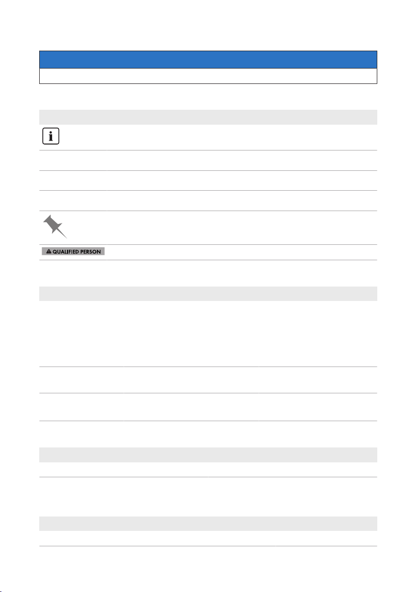
NOTICE
Indicates a situation which, if not avoided, can result in property damage.
1.5 Symbols in the Document
Symbol Explanation
Information that is important for a specific topic or goal, but is not safety-relevant
Indicates a requirement for meeting a specific goal
Desired result
A problem that might occur
Example
Sections describing activities to be performed by qualified persons only
1.6 Typographies in the Document
Typography Use Example
bold
>
[Button]
[Key]
• Messages
• Terminals
• Elements on a user interface
• Elements to be selected
• Elements to be entered
• Connects several elements to be
selected
• Button or key to be selected or
pressed
• Connect the insulated
conductors to the terminals
X703:1 to X703:6.
• Enter 10 in the field
Minutes.
• Select Settings > Date.
• Select [Enter].
SMA Solar Technology AG
1.7 Designation in the document
Complete designation Designation in this document
SunnyHighpowerPEAK3 Sunny Highpower, inverter, product
1.8 Additional Information
For more information, please go to www.SMA-Solar.com.
Title and information content Type of information
"Application for SMAGridGuard Code" Form
Operating manualSHP-US-20-BE-en-106

SMA Solar Technology AG
1 Information on this Document
Title and information content Type of information
"PUBLIC CYBER SECURITY - Guidelines for a Secure PV System
Technical information
Communication"
"Efficiency and Derating"
Technical Information
Efficiency and derating behavior of the SMA inverters
"Grid Support Utility Interactive Inverters"
Technical Information
Information about how to activate and to set the grid supporting features according to UL1741SA
"Parameters and Measured Values"
Technical Information
Overview of all inverter operating parameters and their configuration options
"SMA and SunSpec Modbus® Interface"
Technical Information
Information on the Modbus interface
"Modbus® parameters and measured values"
Technical Information
Device-specific register HTML file
"Temperature Derating" Technical Information
Important Requirements for Medium-Voltage Transformers
Technical Information
Requirements for Medium-Voltage Transformers
Operating manual SHP-US-20-BE-en-10 7

2 Safety
SMA Solar Technology AG
2 Safety
2.1 Intended Use
The SunnyHighpower is a transformerless PVinverter that converts the direct current from the
PVarray into grid-compliant three-phase current. An external transformer fitted downstream feeds
the alternating current generated into the utility grid.
The product is intended for use in commercial, industrial or business sectors.
The product complies with IEC60721-3-4 as per Class4C2 and is suitable for operation in a
chemically active environment.
The product is suitable for indoor and outdoor use.
The product must only be operated with PV modules of protection class II in accordance with
IEC61730, application class A. The PV modules must be compatible with this product.
The product must only be operated with PV arrays (PV modules and cabling) that are approved by
the electrical standards applicable on-site and the NationalElectricalCode® ANSI/NFPA 70 or
the CanadianElectricalCode® CSA C22.1.
The product may only be operated in connection with a suitable medium-voltage transformer. The
low-voltage side must be configured in a star formation and the neutral point must be grounded (for
information about the requirements of the medium-voltage transformer, consult the technical
information "Important Requirements for Medium-Voltage Transformers" under www.SMASolar.com).
No galvanic isolation
The product is not equipped with a transformer and therefore has no galvanic isolation.
• Do not operate grounded PV modules together with the product. If grounded PV modules
are connected to the product, an event will occur. The event will be displayed, along with
the associated message, in the event list on the user interface of the product.
• Only ground the mounting frames of the PV modules.
PV modules with a high capacity to ground may only be used if their coupling capacity does not
exceed 32μF.
To protect the PV system against excessive reverse currents under fault conditions, a DC-side
overcurrent protective device must be connected in accordance with the National Electrical Code
to prevent any short-circuit currents that exceed the ampacity of the DC electric circuit or the
maximum series fuse rating of the PV modules. Typically, string fuses are used if more than two
strings are connected in parallel.
All components must remain within their permitted operating ranges and their installation
requirements at all times.
The product is approved for the US and Canadian market.
Use SMA products only in accordance with the information provided in the enclosed
documentation and with the locally applicable laws, regulations, standards and directives. Any
other application may cause personal injury or property damage.
®
Operating manualSHP-US-20-BE-en-108
SMA Solar Technology AG
Alterations to SMA products, e.g., changes or modifications, are only permitted with the express
written permission of and according to the instructions from SMA Solar Technology AG.
Unauthorized alterations can be dangerous and lead to personal injury. In addition, an
unauthorized alteration will void guarantee and warranty claims and in most cases terminate the
operating license. SMA Solar Technology AG shall not be held liable for any damage caused by
such changes.
Any use of the product other than that described in the Intended Use section does not qualify as the
intended use.
The enclosed documentation is an integral part of this product. Keep the documentation in a
convenient, dry place for future reference and observe all instructions contained therein.
This document does not replace and is not intended to replace any local, state, provincial, federal
or national laws, regulations or codes applicable to the installation, electrical safety and use of the
product. SMA Solar Technology AG assumes no responsibility for the compliance or noncompliance with such laws or codes in connection with the installation of the product.
The type label must remain permanently attached to the product.
2 Safety
2.2 IMPORTANT SAFETY INSTRUCTIONS
SAVE THESE INSTRUCTIONS
This section contains safety information that must be observed at all times when working.
The product has been designed and tested in accordance with international safety requirements. As
with all electrical or electronical devices, there are residual risks despite careful construction. To
prevent personal injury and property damage and to ensure long-term operation of the product,
read this section carefully and observe all safety information at all times.
DANGER
Danger to life due to electric shock when live components or DC cables are
touched
When exposed to sunlight, the PV modules generate high DC voltage which is present in the DC
cables. Touching live DC cables results in death or lethal injuries due to electric shock.
• Do not touch non-insulated parts or cables.
• Install external DC load-break switch (e.g., a PV junction box including a load-break switch)
between the inverter and PV array.
• Disconnect the PV array from the inverter via an external DC load-break switch (e.g. via a
PV junction including a load-break switch). Switch off and secure the DC load-break switch
against reconnection.
• Disconnect the product from voltage sources and make sure it cannot be reconnected
before working on the device.
• Wear suitable personal protective equipment for all work on the product.
Operating manual SHP-US-20-BE-en-10 9
2 Safety
SMA Solar Technology AG
DANGER
Danger to life due to electric shock from touching an ungrounded PV module
or array frame
Touching ungrounded PV modules or array frames results in death or lethal injuries due to electric
shock.
• Connect and ground the frame of the PV modules, the array frame and the electrically
conductive surfaces so that there is continuous conduction. Observe the applicable local
regulations.
DANGER
Danger to life due to electric shock when touching live system components in
case of a ground fault
If a ground fault occurs, parts of the system may still be live. Touching live parts and cables
results in death or lethal injuries due to electric shock.
• Disconnect the product from voltage sources and make sure it cannot be reconnected
before working on the device.
• Touch the cables of the PV array on the insulation only.
• Do not touch any parts of the substructure or frame of the PV array.
• Do not connect PV strings with ground faults to the inverter.
• Ensure that no voltage is present and wait five minutes before touching any parts of the PV
system or the product.
DANGER
Danger to life due to electric shock in case of overvoltages and if surge
protection is missing
Overvoltages (e.g. in the event of a flash of lightning) can be further conducted into the building
and to other connected devices in the same network via the network cables or other data cables
if there is no surge protection. Touching live parts and cables results in death or lethal injuries due
to electric shock.
• Ensure that all devices in the same network are integrated in the existing overvoltage
protection.
• When laying the network cable outdoors, ensure that there is suitable surge protection at
the network cable transition from the product outdoors to the network inside the building.
• The Ethernet interface of the inverter is classified as "TNV-1" and offers protection against
overvoltages of up to 1.5kV.
Operating manualSHP-US-20-BE-en-1010
SMA Solar Technology AG
2 Safety
WARNING
Danger to life due to fire or explosion
In rare cases, an explosive gas mixture can be generated inside the product under fault
conditions. In this state, switching operations can cause a fire or explosion. Death or lethal
injuries due to fire or flying debris can result.
• In case of error, only carry out corrective measures specified by SMA Solar Technology AG
(see Section12 "Troubleshooting", page61). If no corrective measures are specified, do
not perform any actions on the product. Contact the Service.
• Ensure that unauthorized persons have no access to the product.
• Disconnect the AC circuit breaker and secure it against reconnection.
• Disconnect the PV array from the product via an external disconnection device.
WARNING
Risk of fire due to failure to observe torque specifications on live bolted
connections
Failure to follow the specified torques reduces the ampacity of live bolted connections so that the
contact resistances increase. This can cause components to overheat and catch fire.
• Ensure that live bolted connections are always tightened with the exact torque specified in
this document.
• When working on the device, use suitable tools only.
• Avoid repeated tightening of live bolted connections as this may result in inadmissibly high
torques.
CAUTION
Risk of burns due to hot enclosure parts
Some parts of the enclosure can get hot during operation.
• During operation, do not touch any parts other than the enclosure lid of the inverter.
• Wait until the inverter has cooled down before touching the enclosure.
Operating manual SHP-US-20-BE-en-10 11
2 Safety
SMA Solar Technology AG
CAUTION
Risk of injury due to weight of product
Injuries may result if the product is lifted incorrectly or dropped while being transported or
mounted.
• Transport and lift the product carefully. Take the weight of the product into account.
• Wear suitable personal protective equipment for all work on the product.
• Transport the product using the carrying handles or hoist. Take the weight of the product
into account.
• Use all carrying handles provided during transport with carrying handles.
• Do not use the carrying handles as attachment points for hoist equipment (e.g. straps, ropes,
chains). Insert eye bolts into threads provided on top of the product to attach the hoist
system.
NOTICE
Damage to the enclosure seal in subfreezing conditions
If you open the product when temperatures are below freezing, the enclosure seals can be
damaged. Moisture can penetrate the product and damage it.
• Only open the product if the ambient temperature is not below -5°C (23°F).
• If a layer of ice has formed on the enclosure seal when temperatures are below freezing,
remove it prior to opening the product (e.g. by melting the ice with warm air). Observe the
applicable safety regulations.
NOTICE
Damage to the product due to sand, dust and moisture ingress
Sand, dust and moisture penetration can damage the product and impair its functionality.
• Only open the product if the humidity is within the thresholds and the environment is free of
sand and dust.
• Do not open the product during a dust storm or precipitation.
• Close tightly all enclosure openings.
• Only use listed rain-tight or liquid-tight conduit fittings to attach the conduits to the product.
NOTICE
Damage due to cleaning agents
The use of cleaning agents may cause damage to the product and its components.
• Clean the product and all its components only with a cloth moistened with clear water.
Operating manualSHP-US-20-BE-en-1012
SMA Solar Technology AG
NOTICE
Damage to the inverter due to electrostatic discharge
Touching electronic components can cause damage to or destroy the inverter through
electrostatic discharge.
• Ground yourself before touching any component.
NOTICE
Destruction of the measuring device due to overvoltage
• Only use measuring devices with a measurement range designed for the maximum AC and
DC voltage of the inverter.
Electrical installations (for North America)
All installations must conform with the laws, regulations, codes and standards applicable in the
jurisdiction of installation (e.g. National Electrical Code® ANSI/NFPA 70 or Canadian
Electrical Code® CSA-C22.1.).
• Before connecting the product to the utility grid, contact your local grid operator. The
electrical connection of the product must be carried out by qualified persons only.
• Ensure that the cables or conductors used for electrical connection are not damaged.
2 Safety
Operating manual SHP-US-20-BE-en-10 13
3 Scope of Delivery
A
K
FE
C
D
G
PL O
M
N
H
J
B
I
SMA Solar Technology AG
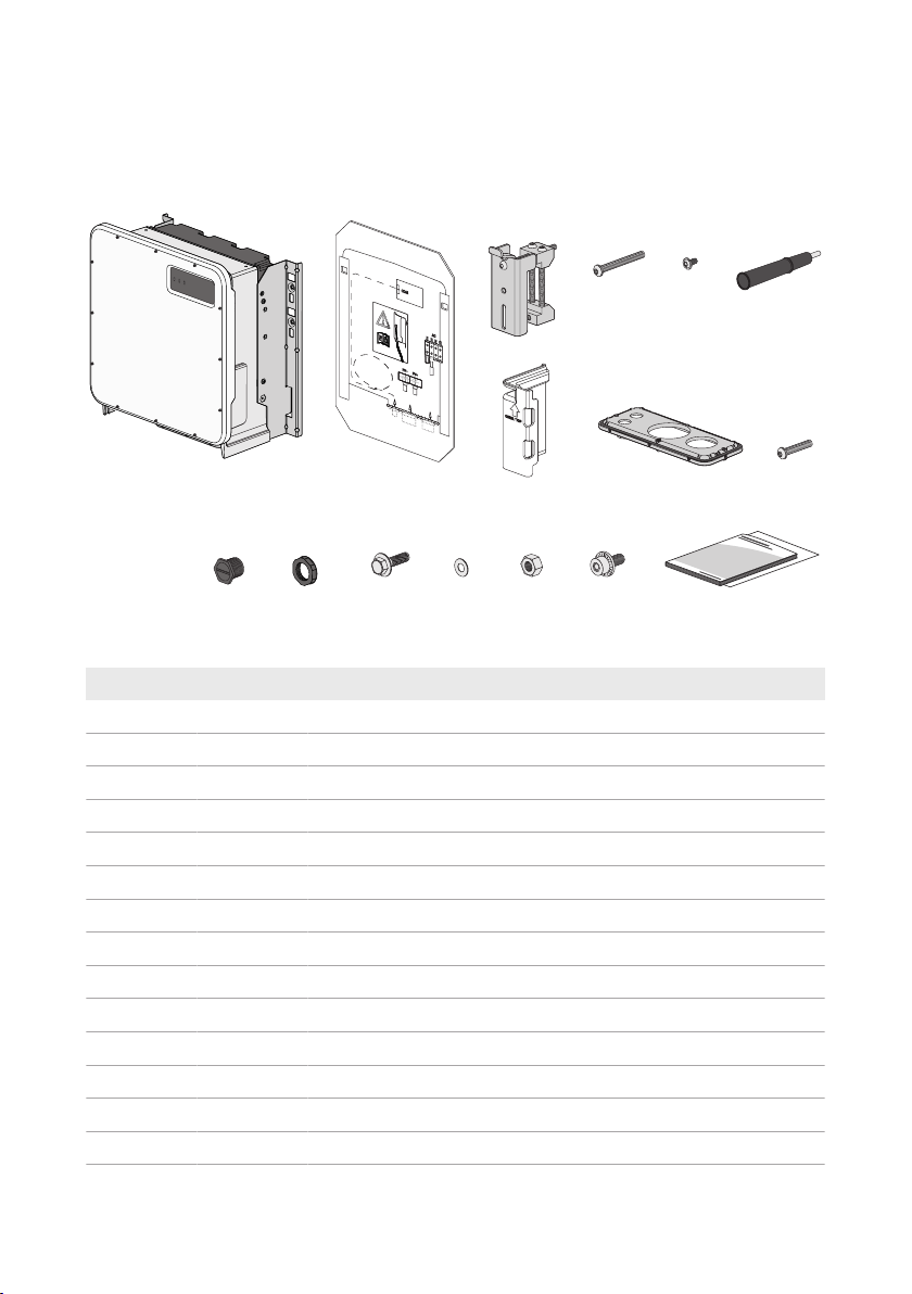
3 Scope of Delivery
Check the scope of delivery for completeness and any externally visible damage. Contact your
distributor if the scope of delivery is incomplete or damaged.
Figure 1: Components included in the scope of delivery
Position Quantity Designation
A 1 Inverter
B 1 Mounting template
C 2 Mounting bracket
D 2 Button head screw M8x105
E 2 Button head screw M8x16
F 4 Carry handle
G 4 Touch protection for DC connection
H 1 Connecting plate
I 3 Button head screw M8x70
J 1 Sealing plug (21mm (0.75in))
K 1 Counter nut for sealing plug (21mm (0.75in))
L 2 M10x40 combination hexagon head screw
M 2 Washer M10
N 2 Hexagon nut M10
Operating manualSHP-US-20-BE-en-1014

SMA Solar Technology AG
3 Scope of Delivery
Position Quantity Designation
O 2 M6x16 combined screw
P 1 Quick reference guide, production test report, supplementary sheet
with the default settings
Operating manual SHP-US-20-BE-en-10 15

4 Additionally Required Materials and Equipment
SMA Solar Technology AG
4 Additionally Required Materials and Equipment
Material or equipment Quan-
tity
Profile rail (length: min. 770mm (30.3in),
depth: max. 60mm (2.4), height: 50mm to
80mm (2in to 3in)
Conduit (trade size: 76.2mm (3in) or smaller
with suitable reducer bush) for the DC connection
Raintight or liquidtight conduit fitting (trade size:
76.2mm (3in) or smaller with suitable reducer
bush) for DC connection
Conduit (trade size: 63.5mm (2.5in) or smaller
with suitable reducer bush) for DC connection
Raintight or liquidtight conduit fitting (trade size:
63.5mm (2.5in) or smaller with suitable reducer bush) for AC connection
Conduit (trade size: 19.05mm (0.75in) or
smaller with suitable reducer bush) for network
connection
Raintight or liquidtight conduit fitting (trade size:
19.05mm (0.75in) or smaller with suitable reducer bush) for network connection
Terminal lugs (flange hole: M10) 2 Used for positive and negative DC ca-
Terminal lugs (flange hole: M6) 1 Used for equipment grounding con-
RJ45 plugs, field assembly 1-2 Only required if the network cables
Means of transport (e.g. pallet truck) 1 Used to transport packed product to
Eye bolt (M10) 2 Only required if the product is to be
Hoist 1 Only required if the product is to be
Utility knife 1 Used to unpack the product
Torx screwdriver (TX25) 1 Used to attach and remove transport
2 For mounting the product
1 Only necessary if DC cables must be
1 Only necessary if DC cables must be
1 Only necessary if AC cables must be
1 Only necessary if AC cables must be
1 Only necessary if network cables must
1 Only necessary if network cables must
Explanation
laid in one conduit
laid in one conduit
laid in one conduit
laid in one conduit
be laid in one conduit
be laid in one conduit
ble
ductor
are not equipped with RJ45 plugs
mounting location
transported with a hoist
transported with a hoist
handles and enclosure lid
Operating manualSHP-US-20-BE-en-1016

SMA Solar Technology AG
4 Additionally Required Materials and Equipment
Material or equipment Quan-
Explanation
tity
Torx screwdriver (TX40) 1 Used to attach mounting brackets, in-
verters to mounting brackets, connecting plate to inverter; used to connect
equipment grounding conductor of PV
array
Allen key (AF5) 1 Used for connecting grounding con-
ductor
Allen key (AF8) 1 Used for connecting L1, L2 an L3
Measuring device with a measurement range
1 For verifying that no voltage is present
designed for the maximum AC and DC voltage
of the inverter
Current clamp 1 For verifying that no voltage is present
Press tool 1 Used to attach terminal lugs to DC ca-
bles
Clean cloth 1 Used to clean terminal lugs
Ethanol cleaning agent 1 Used to clean terminal lugs
Brush 1 Used to clean aluminum conductor
(only necessary if cable is made of
aluminum)
Protective grease 1 Used to apply to aluminum conductor
(only necessary if cable is made of
aluminum)
Operating manual SHP-US-20-BE-en-10 17
5 Product Overview
A
B
5 Product Overview
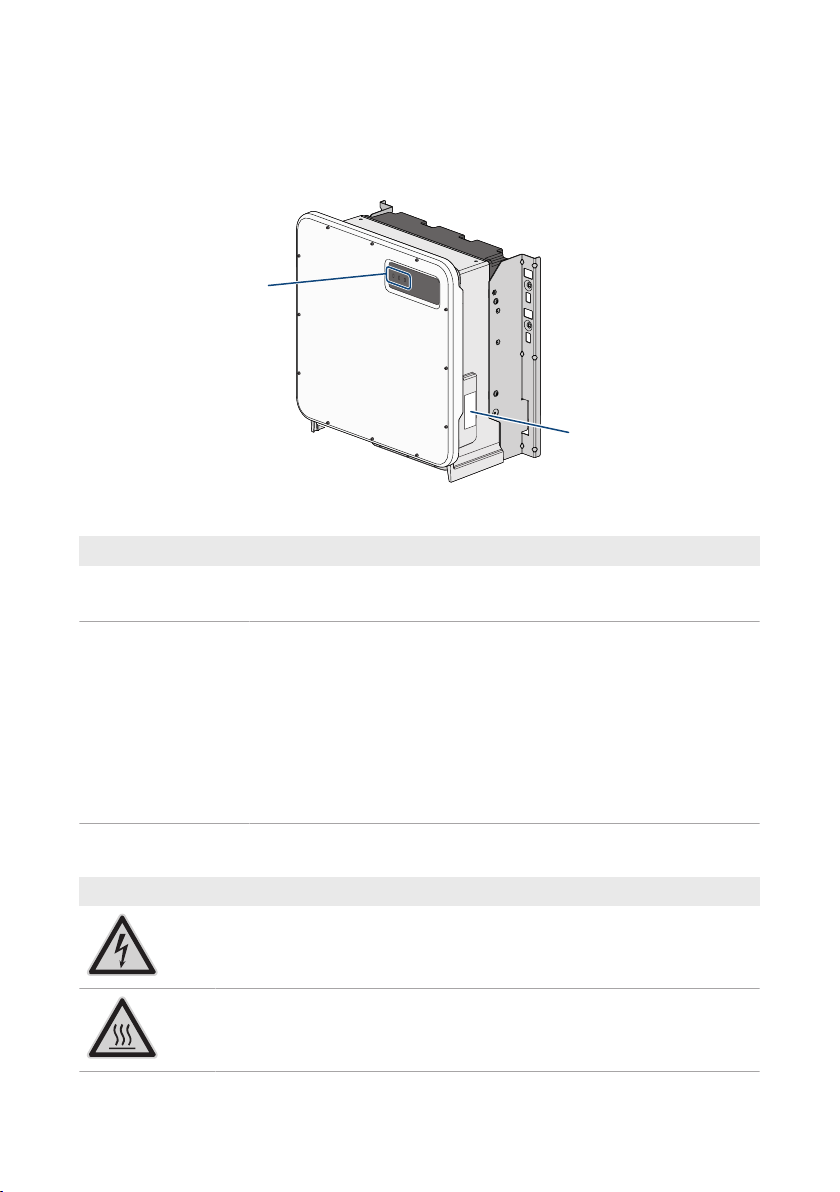
5.1 Product Description
Figure 2: Design of the product
Position Designation
A LEDs
The LEDs indicate the operating state of the inverter.
B Type label
The type label clearly identifies the product. The type label must remain
permanently attached to the product. You will find the following information on the type label:
• Device type (Model)
• Serial number (Serial No. or S/N)
• Date of manufacture
• Device-specific characteristics
SMA Solar Technology AG
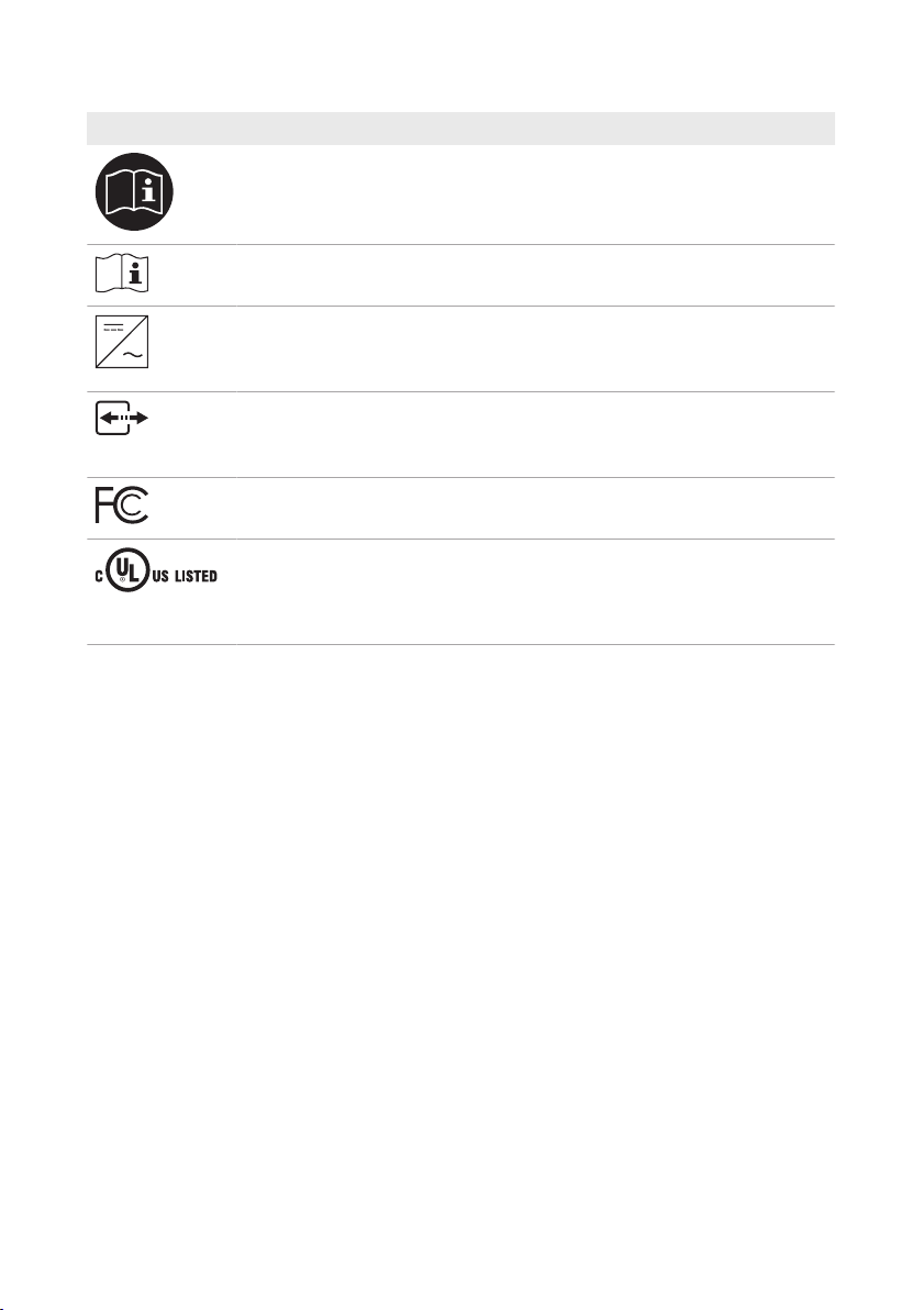
5.2 Symbols on the Product
Symbol Explanation
Beware of electrical voltage
The product operates at high voltages.
Beware of hot surface
The product can get hot during operation.
Operating manualSHP-US-20-BE-en-1018
SMA Solar Technology AG
Symbol Explanation
Observe the documentation
Observe all documentation supplied with the product.
Observe the documentation
Together with the red LED, this symbol indicates an error.
Inverter
Together with the green LED, this symbol indicates the operating state of the in-
verter.
Data transmission
Together with the blue LED, this symbol indicates the status of the network con-
nection.
FCC designation
The product complies with the requirements of the applicable FCC standards.
UL62109-1 and CAN/CSA-C22.2 No. 62109-1:16 are the standards applied by Underwriters Laboratories to the product to certify that it meets the requirements of the National Electrical Code®, the Canadian Electrical Code
and IEEE1547.
5 Product Overview
5.3 Interfaces and Functions
The inverter can be equipped or retrofitted with the following interfaces and functions:
®
User interface for monitoring and configuration
The product is equipped as standard with an integrated webserver, which provides a user interface
for configuring and monitoring the product. The product user interface can be called up via the web
browser if there is an existing connection to an end device (e.g. computer, tablet PC or
smartphone).
Smart Inverter Screen
The Smart Inverter Screen enables you to view the status display and to display the current power
and consumption on the user interface login page. This gives you an overview of the most important
inverter data without having to log into the user interface.
The Smart Inverter Screen is deactivated by default. The Smart Inverter Screen can be activated via
the user interface once the inverter has been commissioned.
SMA Speedwire
The product is equipped with SMASpeedwire as standard. SMASpeedwire is a type of
communication based on the Ethernet standard. SMASpeedwire is designed for a data transfer
rate of 100Mbps and enables optimum communication between Speedwire devices within
systems.
Operating manual SHP-US-20-BE-en-10 19

5 Product Overview
SMA Solar Technology AG
SMA Webconnect
The inverter is equipped with a Webconnect function as standard. The Webconnect function
enables direct data transmission between the inverter and SunnyPortal without any additional
communication device and for a maximum of 4 inverters per visualized system. In PV systems with
more than 4 inverters, there is the option of establishing data transmission between the inverters
and SunnyPortal via the data logger (e.g., SMADataManager) or distributing the inverters over
several systems. You can directly access your visualized system via the web browser on your end
device.
Modbus
The product is equipped with a Modbus interface. The Modbus interface is deactivated by default
and must be configured as needed.
The Modbus interface of the supported SMA products is designed for industrial use – via SCADA
systems, for example – and has the following tasks:
• Remote query of measured values
• Remote setting of operating parameters
• Setpoint specifications for system control
Grid Management Services
The inverter is a grid support interactive inverter.
The inverter was tested in accordance with the UL1741 SA (2016-09-07) to be compliant with the
source requirements documents of the states available at the time. For connecting the inverter to the
utility grid, no additional grid monitoring equipment is necessary. A description of the tested
functions and instructions on the activation and setting of functions can be found in the technical
information "Grid Support Utility Interactive Inverters" at www.SMA-Solar.com.
SMA Smart Connected
SMA Smart Connected is the free monitoring of the inverter via the SMA SunnyPortal. Thanks to
SMA Smart Connected, the PV system operator and qualified person will be informed automatically
and proactively about inverter events that occur.
SMA Smart Connected is activated during registration in SunnyPortal. In order to use SMA Smart
Connected, it is necessary that the inverter is permanently connected to SunnyPortal and the data
of the PV system operator and qualified person is stored in SunnyPortal and up-to-date.
5.4 LED Signals
The LEDs indicate the operating state of the inverter.
LED signal Explanation
The green LED is flashing
(twoseconds on and
twoseconds off)
The green LED flashes
quickly
Waiting for feed-in conditions
The conditions for feed-in operation are not yet met. As soon as the
conditions are met, the inverter will start feed-in operation.
Update of central processing unit
The central processing unit of the inverter is being updated.
Operating manualSHP-US-20-BE-en-1020

SMA Solar Technology AG
LED signal Explanation
The green LED is glowing Feed-in operation
The inverter feeds in with a power of at least 90%.
The green LED is pulsing Feed-in operation
The inverter is equipped with a dynamic power display via the green
LED. Depending on the power, the green LED pulses fast or slow. If
necessary, you can switch off the dynamic power display via the
green LED.
The green LED is off The inverter is not feeding into the utility grid.
The red LED is glowing Event occurred
If an event occurs, a distinct event message and the corresponding
event number will be displayed in addition on the inverter user interface or in the communication product (e.g. SMADataManager).
The blue LED flashes slowly
for approx. one minute
Communication connection is being established
The inverter is establishing a connection to a local network or is es-
tablishing a direct connection to an end device via Ethernet (e.g.
computer, tablet PC or smartphone).
The blue LED is glowing Communication active
There is an active connection with a local network or there is a direct connection with an end device via Ethernet (e.g. computer,
tablet PC or smartphone).
5 Product Overview
Operating manual SHP-US-20-BE-en-10 21
6 Mounting and Preparing the Connection
SMA Solar Technology AG
6 Mounting and Preparing the Connection
6.1 Requirements for Mounting
Requirements for the Mounting Location:
WARNING
Danger to life due to fire or explosion
Despite careful construction, electrical devices can cause fires.
• Do not mount the product in areas containing highly flammable materials or gases.
• Do not mount the product in potentially explosive atmospheres.
☐ Do not mount the inverter in living areas.
☐ The installation site can be exposed to direct solar irradiation. There is, however, the possibility
that the product reduces its power output to avoid overheating due to high temperatures.
☐ All ambient conditions must be met (see Section15, page88).
☐ At least two profile rails must be available for mounting.
☐ The support surface of the frame to which the profile rails are attached should be firm and
level (e.g. concrete). Non-fulfillment of these criteria may restrict servicing.
Requirements for the profile rails:
☐ The profile rails must be designed for the load and orientation of the inverters in the PV system.
The profile rails might need to be reinforced.
☐ The profile rails must be designed for the clamping range of the mounting bracket.
Operating manualSHP-US-20-BE-en-1022
SMA Solar Technology AG
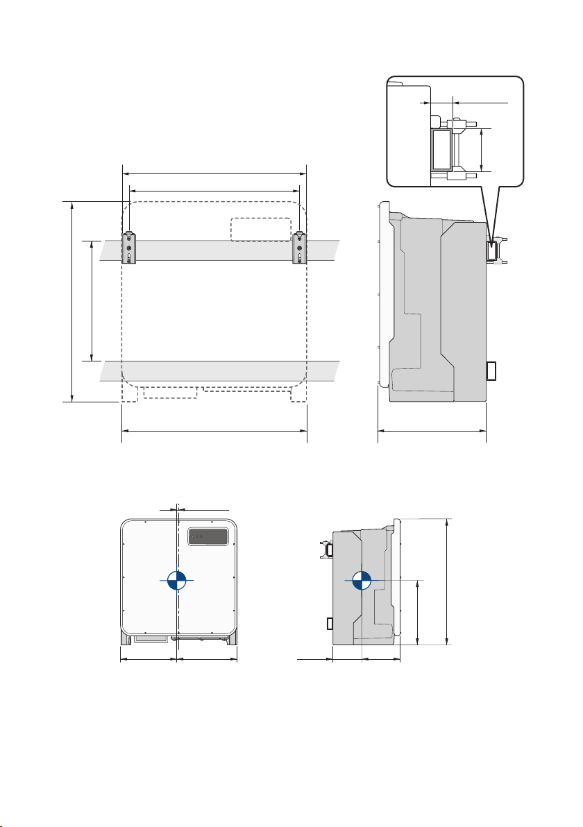
833 (32.8)
700 (27.56)
767.5 (30.2)
770 (30.3) 450.6 (17.7)
500 − 550
(19.7 − 21.7)
40 − 60
(1.57 − 2.36)
50 − 80
(2 − 3.15)
376.7
(14.8)
393.4
(15.5)
8.4 (0.3)
832.7 (32.8)
369.2
(14.5)
188.9
(7.4)
254.8
(10)
6 Mounting and Preparing the Connection
Figure 3: Dimensions of the profile rails and the clamping range of the mounting bracket (dimensions in mm (in))
Center of gravity:
Figure 4: Dimensions of the center of gravity of the product (dimensions in mm (in))
Operating manual SHP-US-20-BE-en-10 23
6 Mounting and Preparing the Connection
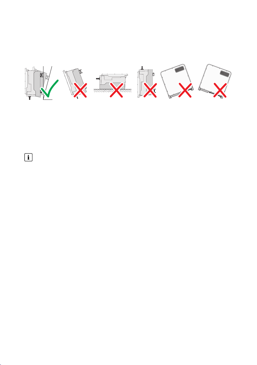
10°
SMA Solar Technology AG
Permitted and prohibited mounting positions:
☐ The product may only be mounted in a permitted position. This will ensure that no moisture can
penetrate the product.
☐ The product should be mounted such that the LED signals can be read off without difficulty.
Figure 5: Permitted and prohibited mounting positions
Recommended Clearances:
To guarantee optimal operation and adequate heat dissipation for the inverter, the following
requirements for clearances should be observed. This will prevent the inverter power output from
being reduced due to excessive temperatures. However, smaller clearances are permitted without
causing any risk.
Prescribed clearances in accordance with the
Canadian Electrical Code
®
CSA C22.1
National Electrical Code
Under certain conditions, the National Electrical Code® or the Canadian Electrical Code
®
or
®
CSA C22.1 specify greater clearances.
• Ensure that the prescribed clearances in accordance with the National Electrical Code
or Canadian Electrical Code® CSA C22.1 are adhered to.
☐ Maintain the recommended clearances to walls as well as to other inverters or objects.
®
Operating manualSHP-US-20-BE-en-1024
SMA Solar Technology AG
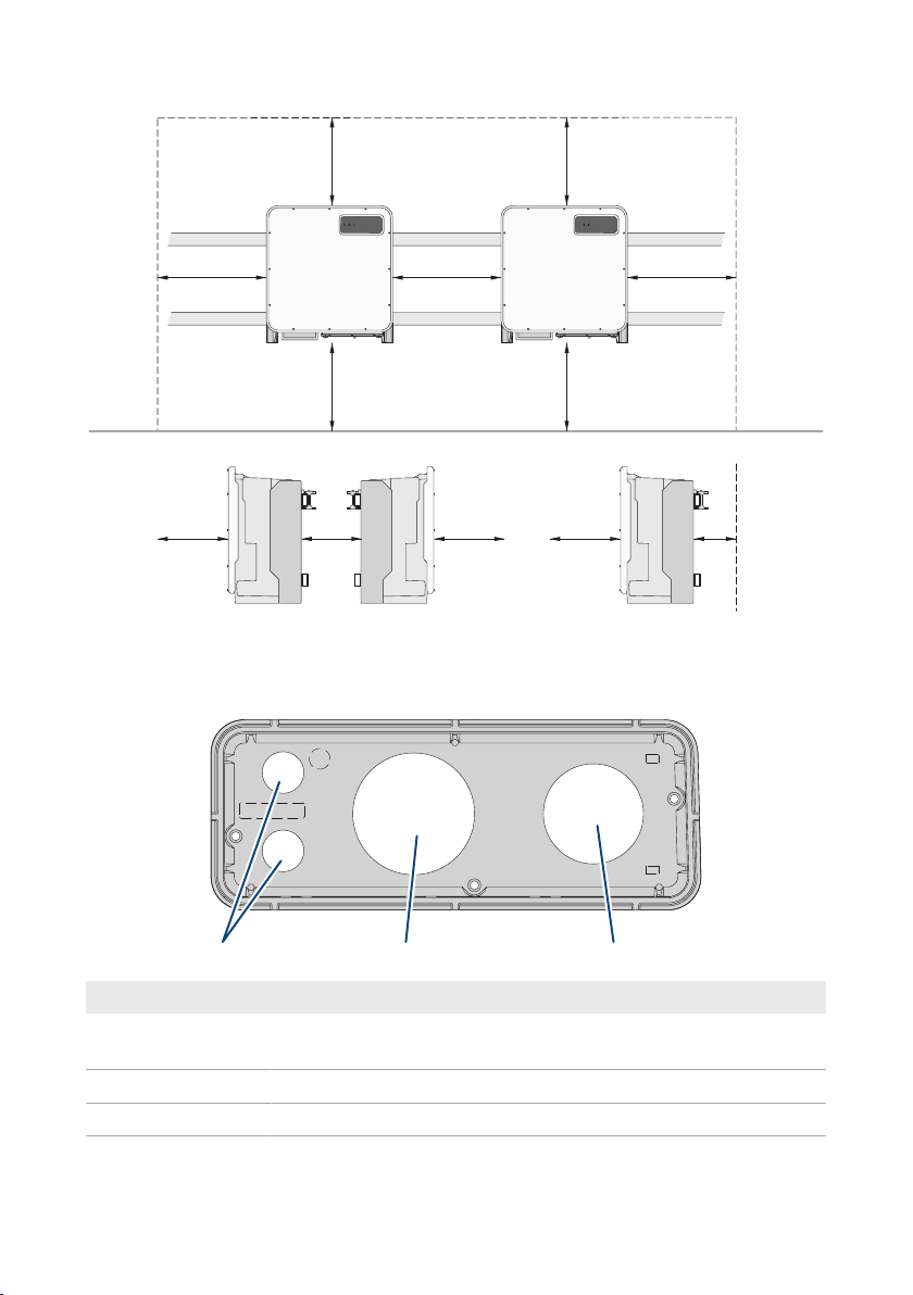
500
(19.7)
500
(19.7)
500
(19.7)
500
(19.7)
100
(3.9)
500
(19.7)
500
(19.7)
500
(19.7)
500
(19.7)
500
(19.7)
500
(19.7)
200
(7.9)
A B C
Figure 6: Recommended clearances(Dimensions in mm (in))
6.2 Overview of Connecting Plate
6 Mounting and Preparing the Connection
Position Designation
A Entry for the network cables (for 19.05 mm (0.75 in) trade size con-
duits))
B Entry for the DC cables (for 76.2 mm (3 in) trade size conduits))
C Entry for the AC cables (for 63.5 mm (2.5 in) trade size conduits))
Operating manual SHP-US-20-BE-en-10 25
6 Mounting and Preparing the Connection
2
1
SMA Solar Technology AG
6.3 Mounting the Product and Preparing the Connection
DANGER
Danger to life due to electric shock when live cables are touched
High voltages are present on the AC and DC cables. Touching live cables results in death or
lethal injuries due to electric shock.
• Do not touch non-insulated parts or cables.
• Disconnect the AC circuit breaker and secure it against reconnection.
• Disconnect the PV array from the inverter via an external DC load-break switch (e.g. via a
PV junction including a load-break switch). Switch off and secure the DC load-break switch
against reconnection.
• Ensure that all cables to be connected are de-energized.
• Wear suitable personal protective equipment for all work on the product.
CAUTION
Risk of injury due to weight of product
Injuries may result if the product is lifted incorrectly or dropped while being transported or
mounted.
• Transport and lift the product carefully. Take the weight of the product into account.
• Wear suitable personal protective equipment for all work on the product.
• Transport the product using the carrying handles or hoist. Take the weight of the product
into account.
• Use all carrying handles provided during transport with carrying handles.
• Do not use the carrying handles as attachment points for hoist equipment (e.g. straps, ropes,
chains). Insert eye bolts into threads provided on top of the product to attach the hoist
system.
Procedure:
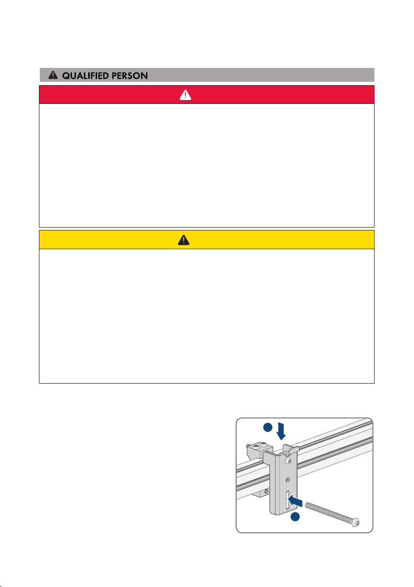
1. Mark the position for the mounting brackets.
2. Hook each mounting bracket onto the mounting rail
and insert the screw (M8x105).
Operating manualSHP-US-20-BE-en-1026
SMA Solar Technology AG
2
1
2
1
6 Mounting and Preparing the Connection
3. Fasten all four screws of each mounting bracket hand-tight (TX40).
4. Ensure the correct position of the mounting brackets by hooking in the mounting template. If
the position is incorrect, move the mounting brackets to the correct position.
5. Tighten all four screws of each mounting bracket (TX40, torque: 12Nm ± 2Nm (106in-lb ±
17.7in-lb)).
6. Clip the mounting template into the mounting brackets.
7. Align the cable conduits by means of the mounting template and shorten if necessary. Take the
product depth of 400mm (15.8in) into account.
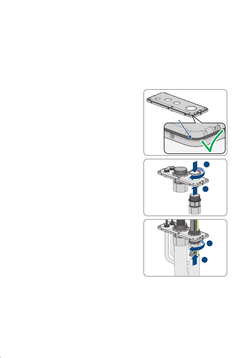
8. Check on the connection plate whether the seal is
present and undamaged.
9. Attach the conduit fittings for attachment of the
conduits to the connecting plate.
10. Lead the cables through the conduit fittings in the
connecting plate and align the connecting plate
using the mounting template.
11. Remove the mounting template.
Operating manual SHP-US-20-BE-en-10 27
6 Mounting and Preparing the Connection
4x
90°
4x
12x
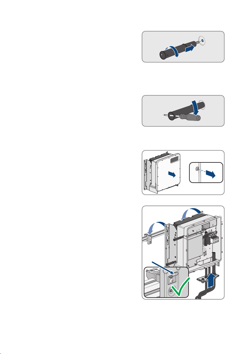
12. Screw the transport handles as far as they will go
into the taps on the right- and left-hand side until
they lie flush with the enclosure. When doing so,
ensure that the transport handles are screwed into
the taps so that they are perfectly straight. If the
transport handles are not screwed in straight, this
can make it more difficult or even impossible to
unscrew them later on and can damage the taps to
the extent that transport handles can no longer be
screwed into them.
13. Insert a screwdriver into the holes in the transport
handle and turn the screwdriver through 90°. This
ensures that the transport handles are securely
tightened.
14. If the inverter is to be hooked into the mounting brackets by means of a hoist, screw the eye
bolts into the threads on the top of the inverter and attach the hoist to them. The hoist must be
suitable to take the weight of the inverter.
15. Unscrew all screws of the enclosure lid (TX25) and
remove it.
SMA Solar Technology AG
16. Set the screws and the enclosure lid aside and store safely.
17. Hook the product into the mounting brackets. To do
this, guide the product over the cables and the
connecting plate so that the cables protrude through
the opening into the product and the connecting
plate sits under the opening. The bracket must
protrude through the upper opening.
18. Align the cables according to the corresponding terminals and shorten the cables if necessary.
Operating manualSHP-US-20-BE-en-1028
SMA Solar Technology AG
4x
1
2
3x
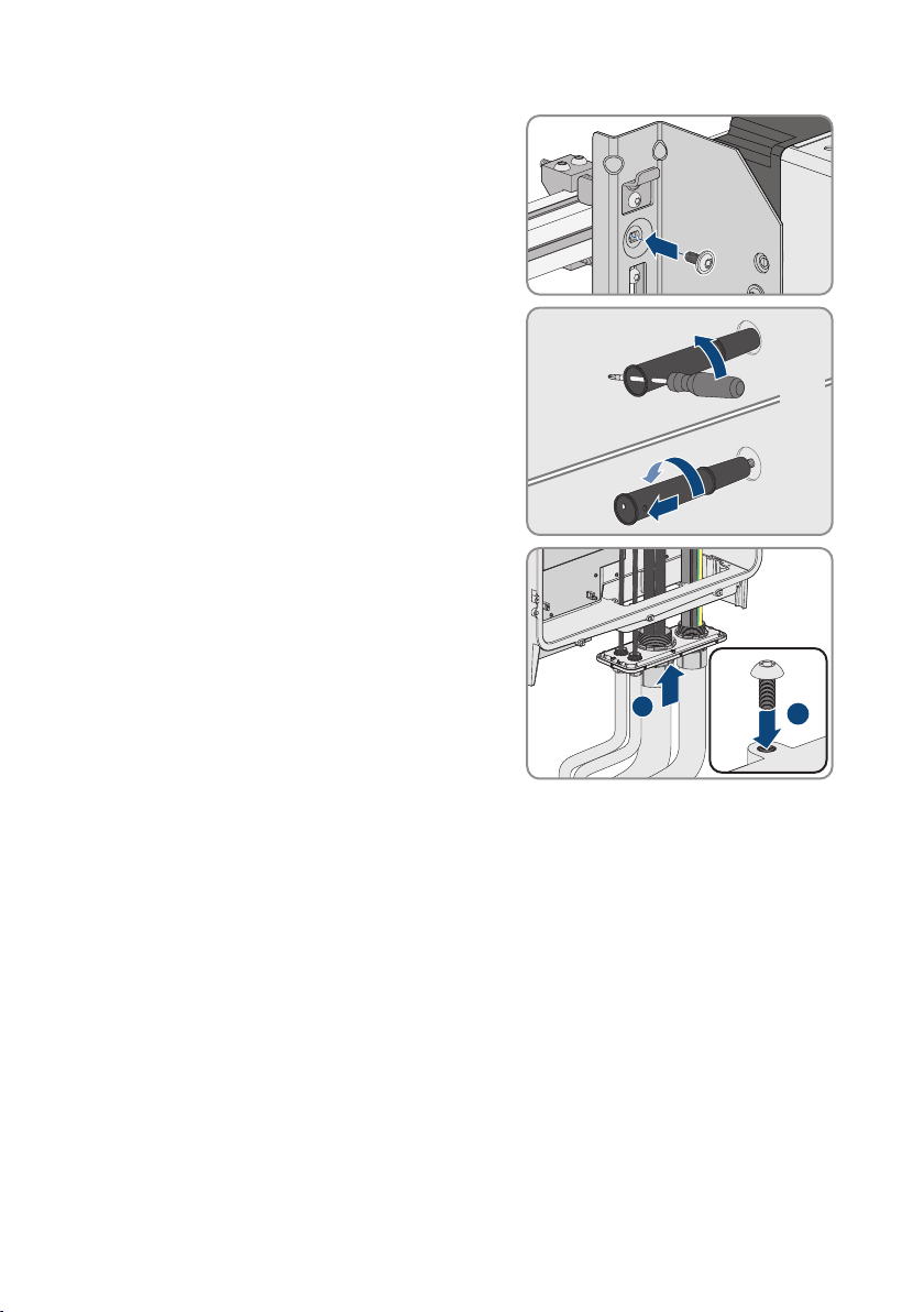
19. Secure the product with one screw each on the right
and left on the mounting bracket (M8x16, TX40,
12Nm ± 2Nm (106in-lb ± 17.7in-lb)).
20. Remove all four transport handles from the threaded
holes. If necessary, insert a screwdriver into the
holes on the transport handle and use the
screwdriver to remove the transport handle.
21. Fasten the connecting plate to the enclosure using
three screws (M8x70, TX40, torque: 8Nm ± 0.5
Nm (71in-lb ± 4in-lb)).
6 Mounting and Preparing the Connection
Operating manual SHP-US-20-BE-en-10 29
 Loading...