

Page 1
Solar data technology
SUNNY DATA CONTROL
Technical Description
SDC-TEN081450 | Version 5.0
EN
Page 2

SMA Technologie AG Table of Contents
Table of Content
1 Notes on this Manual. . . . . . . . . . . . . . . . . . . . . . . . . . . . . . 9
1. 1 Target Group . . . . . . . . . . . . . . . . . . . . . . . . . . . . . . . . . . . . . . . 9
1. 2 Validity . . . . . . . . . . . . . . . . . . . . . . . . . . . . . . . . . . . . . . . . . . . . 9
1. 3 Symbols Used. . . . . . . . . . . . . . . . . . . . . . . . . . . . . . . . . . . . . . . 9
1. 4 Definitions. . . . . . . . . . . . . . . . . . . . . . . . . . . . . . . . . . . . . . . . . 10
1.4. 1 Syntax. . . . . . . . . . . . . . . . . . . . . . . . . . . . . . . . . . . . . . . . . . . . . . . . . . . . . . 10
2 Safety . . . . . . . . . . . . . . . . . . . . . . . . . . . . . . . . . . . . . . . . . 11
2. 1 Appropriate Usage . . . . . . . . . . . . . . . . . . . . . . . . . . . . . . . . . 12
3 Sunny Data Control . . . . . . . . . . . . . . . . . . . . . . . . . . . . . . 13
3. 1 What is new? . . . . . . . . . . . . . . . . . . . . . . . . . . . . . . . . . . . . . . 13
3. 2 Software Version . . . . . . . . . . . . . . . . . . . . . . . . . . . . . . . . . . . 13
3. 3 Functions. . . . . . . . . . . . . . . . . . . . . . . . . . . . . . . . . . . . . . . . . . 13
3. 4 System Requirements . . . . . . . . . . . . . . . . . . . . . . . . . . . . . . . . 14
4 Connecting the PC to an Inverter . . . . . . . . . . . . . . . . . . . 15
4. 1 Connection via the USB service interface . . . . . . . . . . . . . . . . 15
4. 2 Communication via Bluetooth . . . . . . . . . . . . . . . . . . . . . . . . . 16
4. 3 Connection via RS485 and an interface converter. . . . . . . . . 16
5 Connecting the PC to a Communication Device. . . . . . . . 17
5. 1 Notes on the Use of Level Converters . . . . . . . . . . . . . . . . . . . 20
5. 2 Sunny Boy Control / Plus. . . . . . . . . . . . . . . . . . . . . . . . . . . . . 21
5.2. 1 Connection via RS232 . . . . . . . . . . . . . . . . . . . . . . . . . . . . . . . . . . . . . . . . . 21
5.2. 2 Connection via RS485 . . . . . . . . . . . . . . . . . . . . . . . . . . . . . . . . . . . . . . . . . 23
5.2. 3 Connection via the Analog Modem NET Piggy-Back . . . . . . . . . . . . . . . . . 27
5.2. 4 Connection via the ISDN NET Piggy-Back . . . . . . . . . . . . . . . . . . . . . . . . . 28
5.2. 5 Connection via the GSM NET Piggy-Back. . . . . . . . . . . . . . . . . . . . . . . . . . 29
5.2. 6 Connection via the Ethernet NET Piggy-Back. . . . . . . . . . . . . . . . . . . . . . . . 30
5. 3 Sunny Beam . . . . . . . . . . . . . . . . . . . . . . . . . . . . . . . . . . . . . . . 31
Technical Description SDC-TEN081450 2
Page 3

Table of Contents SMA Technologie AG
5.3. 1 Connection via USB . . . . . . . . . . . . . . . . . . . . . . . . . . . . . . . . . . . . . . . . . . . 31
6 Installation . . . . . . . . . . . . . . . . . . . . . . . . . . . . . . . . . . . . . 32
6. 1 Installing Sunny Data Control . . . . . . . . . . . . . . . . . . . . . . . . . 32
7 Sunny Data Control User Interface. . . . . . . . . . . . . . . . . . 33
7. 1 Menu Area . . . . . . . . . . . . . . . . . . . . . . . . . . . . . . . . . . . . . . . . 34
7. 2 Plant tree. . . . . . . . . . . . . . . . . . . . . . . . . . . . . . . . . . . . . . . . . . 35
7. 3 Display Area . . . . . . . . . . . . . . . . . . . . . . . . . . . . . . . . . . . . . . 36
8 Initial Settings . . . . . . . . . . . . . . . . . . . . . . . . . . . . . . . . . . . 37
8. 1 Creating Plants . . . . . . . . . . . . . . . . . . . . . . . . . . . . . . . . . . . . . 37
8.1. 1 Changing Plant Names, Creating / Deleting Plants . . . . . . . . . . . . . . . . . . 37
8. 2 Loading a Plant. . . . . . . . . . . . . . . . . . . . . . . . . . . . . . . . . . . . . 38
8. 3 Setting the Communication Connection. . . . . . . . . . . . . . . . . . 39
8.3. 1 Bluetooth. . . . . . . . . . . . . . . . . . . . . . . . . . . . . . . . . . . . . . . . . . . . . . . . . . . . 39
8.3. 2 COM1 – COM255. . . . . . . . . . . . . . . . . . . . . . . . . . . . . . . . . . . . . . . . . . . 43
8.3. 3 Modem . . . . . . . . . . . . . . . . . . . . . . . . . . . . . . . . . . . . . . . . . . . . . . . . . . . . . 44
8.3. 4 Network . . . . . . . . . . . . . . . . . . . . . . . . . . . . . . . . . . . . . . . . . . . . . . . . . . . . 45
8.3. 5 Sunny Beam (USB) . . . . . . . . . . . . . . . . . . . . . . . . . . . . . . . . . . . . . . . . . . . . 47
8.3. 6 Setting the Transport Protocol. . . . . . . . . . . . . . . . . . . . . . . . . . . . . . . . . . . . 48
8. 4 Detecting Devices. . . . . . . . . . . . . . . . . . . . . . . . . . . . . . . . . . . 49
8.4. 1 Narrowing the Scope of Device Detection . . . . . . . . . . . . . . . . . . . . . . . . . 50
9 Setting Parameters (Installer) . . . . . . . . . . . . . . . . . . . . . . 51
10 Displaying Data . . . . . . . . . . . . . . . . . . . . . . . . . . . . . . . . . 53
10. 1 Creating a Device Overview . . . . . . . . . . . . . . . . . . . . . . . . . . 54
10.1. 1 Displaying or Concealing Devices. . . . . . . . . . . . . . . . . . . . . . . . . . . . . . . . 56
10.1. 2 Arranging the Fields . . . . . . . . . . . . . . . . . . . . . . . . . . . . . . . . . . . . . . . . . . . 57
10.1. 3 Show or Hide the Grid Lines . . . . . . . . . . . . . . . . . . . . . . . . . . . . . . . . . . . . 57
10.1. 4 Setting the Data Query Sequence . . . . . . . . . . . . . . . . . . . . . . . . . . . . . . . . 57
10.1. 5 Maximizing the Device Overview (Online Display) . . . . . . . . . . . . . . . . . . 57
10. 2 Choose the channels for spot value readings.. . . . . . . . . . . . . 58
3 SDC-TEN081450 Technical Description
Page 4

SMA Technologie AG
10. 3 Setting the Performance Display . . . . . . . . . . . . . . . . . . . . . . . 59
10. 4 Setting the Communication Quality . . . . . . . . . . . . . . . . . . . . . 60
10. 5 Changing the Color Behavior of the Device Fields . . . . . . . . . 62
10. 6 Accessing Individual Device Information. . . . . . . . . . . . . . . . . 63
10. 7 Configuring the Total Overview. . . . . . . . . . . . . . . . . . . . . . . . 64
10. 8 Managing the Device Overviews . . . . . . . . . . . . . . . . . . . . . . 67
10.8. 1 Managing the Device Overviews . . . . . . . . . . . . . . . . . . . . . . . . . . . . . . . . 67
10. 9 Activating / Deactivating Spot Value Querying . . . . . . . . . . . 68
11 Managing Data and Saving Data Locally . . . . . . . . . . . . 69
11. 1 Reading Out and Saving Data from Sunny Beam. . . . . . . . . . 69
11. 2 Saving Data in Excel Format . . . . . . . . . . . . . . . . . . . . . . . . . . 70
11. 3 Saving Data in CSV Format . . . . . . . . . . . . . . . . . . . . . . . . . . . 71
11.3. 1 Creating a New CSV Type . . . . . . . . . . . . . . . . . . . . . . . . . . . . . . . . . . . . . 71
11.3. 2 Structure of the Standard CSV Format. . . . . . . . . . . . . . . . . . . . . . . . . . . . . 76
11. 4 Direct Data Acquisition from an Inverter. . . . . . . . . . . . . . . . . 77
11.4. 1 Set data storage . . . . . . . . . . . . . . . . . . . . . . . . . . . . . . . . . . . . . . . . . . . . . . 77
11.4. 2 Saving and Viewing Data . . . . . . . . . . . . . . . . . . . . . . . . . . . . . . . . . . . . . . 80
11.4. 3 Sending Data to Sunny Portal . . . . . . . . . . . . . . . . . . . . . . . . . . . . . . . . . . . 80
11. 5 Setting up Sunny Boy Control Channel Recording . . . . . . . . . 81
11. 6 Reading Out Data Saved on the Sunny Boy Control . . . . . . . 83
11.6. 1 Storage Time Refresh . . . . . . . . . . . . . . . . . . . . . . . . . . . . . . . . . . . . . . . . . . 85
11.6. 2 Setting Time Ranges . . . . . . . . . . . . . . . . . . . . . . . . . . . . . . . . . . . . . . . . . . . 85
11.6. 3 Resetting Time Ranges . . . . . . . . . . . . . . . . . . . . . . . . . . . . . . . . . . . . . . . . . 86
11.6. 4 Structure of the Excel Files . . . . . . . . . . . . . . . . . . . . . . . . . . . . . . . . . . . . . . 87
11. 7 Configuring the Automatic Readout. . . . . . . . . . . . . . . . . . . . . 89
11.7. 1 Starting a New Task. . . . . . . . . . . . . . . . . . . . . . . . . . . . . . . . . . . . . . . . . . . 89
11.7. 2 Editing / Deleting a Task . . . . . . . . . . . . . . . . . . . . . . . . . . . . . . . . . . . . . . . 91
11.7. 3 Deactivating the Automatic Readout . . . . . . . . . . . . . . . . . . . . . . . . . . . . . . 91
11. 8 Creating a Chart in Excel. . . . . . . . . . . . . . . . . . . . . . . . . . . . . 92
11.8. 1 Automatic Analysis . . . . . . . . . . . . . . . . . . . . . . . . . . . . . . . . . . . . . . . . . . . . 93
11.8. 2 Manual Analysis. . . . . . . . . . . . . . . . . . . . . . . . . . . . . . . . . . . . . . . . . . . . . . 95
4 SDC-TEN081450 Technical Description
Page 5

SMA Technologie AG
12 Transferring Data to the Internet . . . . . . . . . . . . . . . . . . . 98
12. 1 System Requirements . . . . . . . . . . . . . . . . . . . . . . . . . . . . . . . . 98
12. 2 Reading Out the Complete Time Range . . . . . . . . . . . . . . . . . 98
12. 3 Configuring Sunny Portal Mail. . . . . . . . . . . . . . . . . . . . . . . . . 99
12. 4 Sending Sunny Portal Mail . . . . . . . . . . . . . . . . . . . . . . . . . .102
12.4. 1 After Automatic Data Query . . . . . . . . . . . . . . . . . . . . . . . . . . . . . . . . . . . 102
12.4. 2 After Manual Data Query . . . . . . . . . . . . . . . . . . . . . . . . . . . . . . . . . . . . . 102
12. 5 Transferring the Device Overview to the Internet . . . . . . . . . 102
12.5. 1 Write Online Data File . . . . . . . . . . . . . . . . . . . . . . . . . . . . . . . . . . . . . . . . 103
12.5. 2 Structure of the Online Data Files. . . . . . . . . . . . . . . . . . . . . . . . . . . . . . . . 104
12. 6 Internet Server (SDC Agent) . . . . . . . . . . . . . . . . . . . . . . . . . 108
12.6. 1 Overview . . . . . . . . . . . . . . . . . . . . . . . . . . . . . . . . . . . . . . . . . . . . . . . . . . 108
12.6. 2 Configuring and Activating the Internet Server . . . . . . . . . . . . . . . . . . . . . 110
12. 7 SDC agent . . . . . . . . . . . . . . . . . . . . . . . . . . . . . . . . . . . . . . . 113
12. 8 The Java Applet . . . . . . . . . . . . . . . . . . . . . . . . . . . . . . . . . . . 116
12.8. 1 General Applet Parameters . . . . . . . . . . . . . . . . . . . . . . . . . . . . . . . . . . . . 117
12.8. 2 Component-specific Parameters . . . . . . . . . . . . . . . . . . . . . . . . . . . . . . . . . 120
12.8. 3 Chart Display . . . . . . . . . . . . . . . . . . . . . . . . . . . . . . . . . . . . . . . . . . . . . . . 124
12.8. 4 Device Field Display. . . . . . . . . . . . . . . . . . . . . . . . . . . . . . . . . . . . . . . . . . 128
12.8. 5 Numerical Display . . . . . . . . . . . . . . . . . . . . . . . . . . . . . . . . . . . . . . . . . . . 129
12.8. 6 Overview of Parameters. . . . . . . . . . . . . . . . . . . . . . . . . . . . . . . . . . . . . . . 131
12.8. 7 Example of an HTML Page . . . . . . . . . . . . . . . . . . . . . . . . . . . . . . . . . . . . 134
13 Additional Functions . . . . . . . . . . . . . . . . . . . . . . . . . . . . 136
13. 1 Replacing a Device . . . . . . . . . . . . . . . . . . . . . . . . . . . . . . . . 136
13.1. 1 Updating the Device Type . . . . . . . . . . . . . . . . . . . . . . . . . . . . . . . . . . . . . 137
13. 2 Open device information . . . . . . . . . . . . . . . . . . . . . . . . . . . . 138
13.2. 1 Setting the Device Name and Device ID . . . . . . . . . . . . . . . . . . . . . . . . . . 139
13.2. 2 Changing a Device's Network Address. . . . . . . . . . . . . . . . . . . . . . . . . . . 140
13. 3 Removing Devices . . . . . . . . . . . . . . . . . . . . . . . . . . . . . . . . . 141
13. 4 Adding a Device . . . . . . . . . . . . . . . . . . . . . . . . . . . . . . . . . . 141
13. 5 Sorting Devices. . . . . . . . . . . . . . . . . . . . . . . . . . . . . . . . . . . . 142
Technical Description SDC-TEN081450 5
Page 6

SMA Technologie AG
13. 6 Creating a Color Palette for Device Fields . . . . . . . . . . . . . . 142
13. 7 Changing the Fonts of Device Fields . . . . . . . . . . . . . . . . . . . 143
13. 8 Background Images . . . . . . . . . . . . . . . . . . . . . . . . . . . . . . . . 143
13. 9 Packet Monitor . . . . . . . . . . . . . . . . . . . . . . . . . . . . . . . . . . . . 145
13. 10 Changing the Security Level (Installer Password).. . . . . . . . . 147
13. 11 Locking the Device Overview (Online Display). . . . . . . . . . .148
13. 12 Timeouts . . . . . . . . . . . . . . . . . . . . . . . . . . . . . . . . . . . . . . . . . 149
13.12. 1 Settings for the Sunny Central Control. . . . . . . . . . . . . . . . . . . . . . . . . . . . 149
14 Troubleshooting . . . . . . . . . . . . . . . . . . . . . . . . . . . . . . . . 150
14. 1 Errors in the Use of Sunny Data Control . . . . . . . . . . . . . . . . 150
14. 2 Java Applet Error Messages . . . . . . . . . . . . . . . . . . . . . . . . . 151
14. 3 Errors in the Bluetooth Installation . . . . . . . . . . . . . . . . . . . . . 152
14.3. 1 FAQ . . . . . . . . . . . . . . . . . . . . . . . . . . . . . . . . . . . . . . . . . . . . . . . . . . . . . . 153
14. 4 Setting the Language . . . . . . . . . . . . . . . . . . . . . . . . . . . . . . . 155
15 Contact . . . . . . . . . . . . . . . . . . . . . . . . . . . . . . . . . . . . . . . 156
6 SDC-TEN081450 Technical Description
Page 7
Notes on this Manual SMA Technologie AG
1 Notes on this Manual
1. 1 Target Group
This documentation is intended for installers and users. Some of the activities described in this
document may only be performed by qualified electricians and are marked with a danger notice.
1. 2 Validity
This documentation for the Sunny Data Control is valid for firmware version 4.0, or later. How to
display the firmware version is described in chapter 3. 2 "Software Version" (Page 13).
1. 3 Symbols Used
The following types of safety warnings and general information are used in these instructions.
DANGER!
"DANGER" indicates a hazardous situation which, if ignored, will result in serious injury
or death!
NOTICE!
"NOTICE" indicates a situation which, if ignored, could result in damage to property.
Information
Information provides tips that are valuable for the optimal installation and operation of
your product.
Technical Description SDC-TEN081450 9
Page 8

Notes on this Manual SMA Technologie AG
1. 4 Definitions
1.4. 1 Syntax
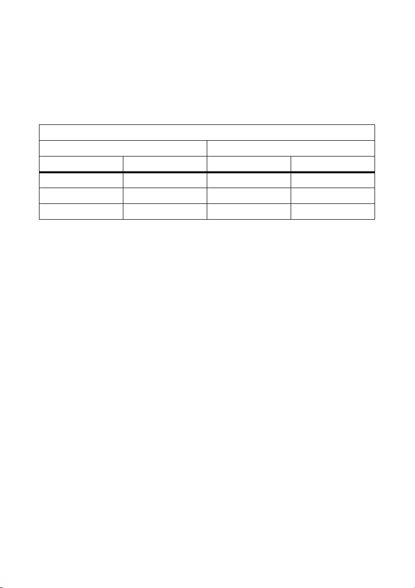
This user manual uses the terminology indicated in the following table.
Example of a typographic convention Description
Click on <Ok>. These symbols represent a button.
Choose "Options / Settings" Menu items are presented in quotation marks.
Multiple menu items are separated by a slash.
Sunny Boy Control/Sunny Boy Control Plus
In these instruction uses the term "Sunny Boy Control/Plus", and it refers to the Sunny Boy Control,
the Sunny Boy Control Plus, and the Sunny Central Control. The Sunny Central Control is a variant
of the Sunny Boy Control which is directly built into the Sunny Central. Throughout this manual, only
the Sunny Boy Control/Plus is mentioned. All sections which apply to the Sunny Boy Control/Plus
also apply to the Sunny Central Control.
10 SDC-TEN081450 Technical Description
Page 9
Safety SMA Technologie AG
2 Safety
Please follow all operating and safety instructions in this section. Failure to follow these instructions
could result in damage to the device and in personal hazard.
DANGER!
Risk of lethal electric shock!
High voltages are present in the inverter.
• Any work on the inverter must be carried out by a qualified personnel!
DANGER!
Death hazard due to changes in the inverter's internal safety
specifications.
Unauthorized changes to the SMA grid guard parameters cancel the operating permit.
• Changes to the SMA grid guard parameters are to be made only with the express
permission of the grid operator.
When using the Internet ensure security by means of a firewall.
When the PC and Sunny Data Control are connected to the Internet parameters could be
changed through unwanted access.
• Protect the PC on which Sunny Data Control is installed from unwanted access from
the Internet by means of hardware and software (firewall) placed upstream from it.
Technical Description SDC-TEN081450 11
Page 10

Safety SMA Technologie AG
2. 1 Appropriate Usage
Sunny Data Control is a PC program which collects, stores and displays data from a PV plant.
Depending on the devices connected, communication is possible through RS232, RS485 and
Bluetooth.
With Sunny Data Control, plant data can be saved in Excel and/or CSV formats. In addition, with
Sunny Data Control the data can be sent to Sunny Portal for their storage and display on the
Internet. Further information regarding Sunny Portal can be found at www.SunnyPortal.com.
Data collected by Sunny Data Control regarding the power generated by your solar power plant
can deviate from those of the electric meter. The data should not be used for billing purposes.
Supported communication devices
• Sunny Boy Control/Plus (starting with firmware version 2.0)
• Sunny Central Control (starting with firmware version 2.0)
•Sunny Beam
Supported inverters for direct connection to the PC
Sunny Data Control supports the direct connection of an inverter to the PC through the USB service
interface with Sunny Data Control software version 3.81, and later. This connection is meant for the
purpose of servicing only, and should not be used on a long-term basis.
• Sunny Boys (except SB400TL-20/5000TL-20), Sunny Mini Centrals, Windy Boy
- Through the USB-Service-Interface (SMA order number: USBPBS)
The SB 4000TL-20/5000TL-20 does not support the USB-Service-Interface. A direct connection to
the PC can be achieved via Bluetooth, or optionally, via RS 485.
• SB 4000TL-20/5000TL-20
- Via Bluetooth
The SB 4000TL-20/5000TL-20 is equipped with Bluetooth as a standard.
The PC requires integrated Bluetooth or a Bluetooth stick and Sunny Data Control software
version 4.0, or later.
- Optional via RS485
The SB 4000TL-20/5000TL-20 requires the 485I module
(SMA order number: DM-485CB-10).
The PC requires the I-7561 interface converter from RS485 to USB.
12 SDC-TEN081450 Technical Description
Page 11
Sunny Data Control SMA Technologie AG
3 Sunny Data Control
3. 1 What is new?
• New SDC user interface design.
• Bluetooth communication with SB4000TL-20/5000TL-20 is possible.
• New "Overview" page with the most important data of the plant or a chosen device.
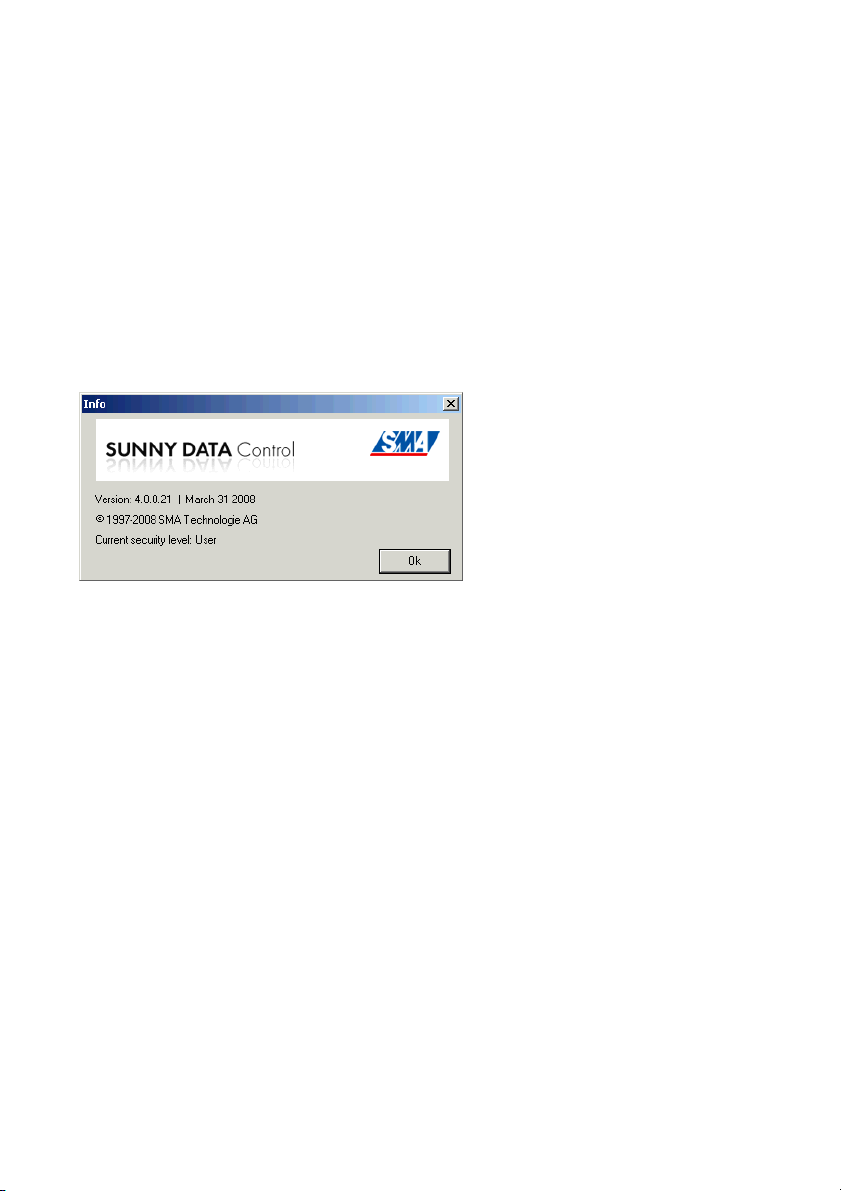
3. 2 Software Version
You can display Sunny Data Control's software version via the menu "?/Info...". The following
information is displayed:
1.
• Software version and date.
• Current security level of the user, see section 13. 10 "Changing the Security Level (Installer
Password)." (Page 147).
3. 3 Functions
• Continuous system monitoring and acquisition of measurement data by means of access to
your Sunny Boy Control.
• Direct measurement data gathering from an inverter through its direct connection to the PC.
• Remote monitoring via modem
• Data export for the presentation of operating data on the Internet (e.g., via Sunny Portal).
• Graphic PC display of all measurement data and operating modes
• "Online display" with color-coded indication of the present output of each Sunny Boy in your
plant
• Configuration of Sunny Boys and adjustment of Sunny Boys' parameters
Technical Description SDC-TEN081450 13
Page 12

Sunny Data Control SMA Technologie AG
3. 4 System Requirements
• Operating systems: Windows 2000, Windows XP, Windows Vista.
• Available hard disk space: At least 20 MB
• Bluetooth
- at the PC: Integrated Bluetooth or with a Bluetooth stick.
- Supported Bluetooth stacks: Microsoft, Toshiba, BlueSoleil, Broadcom
Other Bluetooth stacks can be used via a virtual COM port.
•RS232
- at the PC: COM1 to COM255
- at the Sunny Boy Control: RS232 Piggy-Back
- Data cable: up to 15 m
•RS485
- at the PC: Interface converter.
- at the Sunny Boy Control: RS485 Piggy-Back
- Data cable: Up to 1200 m
•Ethernet
- at the PC: Ethernet card
- at the Sunny Boy Control: NET socket, NET Piggy-Back
- Ethernet: Up to 100 m
•USB
- at the Sunny Beam: Up to 3 m
14 SDC-TEN081450 Technical Description
Page 13
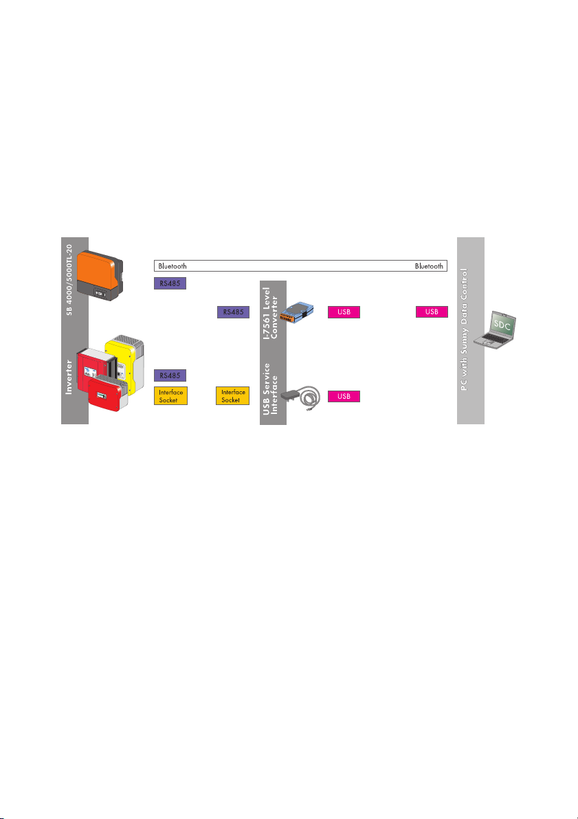
Connecting the PC to an Inverter SMA Technologie AG
4 Connecting the PC to an Inverter
Connection of an inverter to the PC is achieved via the USB service interface, via RS485 and an
interface converter, or via Bluetooth (SB 4000TL-20/5000TL-20). The SB 4000TL-20/5000TL-20
does not support the USB-Service-Interface.
The following chapters describe the respective connection types:
• Connection via the USB service interface
• Connection via Bluetooth
• Connection via RS485 and an interface converter
4. 1 Connection via the USB service interface
Requirements
Connection via the USB service interface (SMA order number: USBPBS) is only for the purpose of
servicing, and should not be used long term. The SB 4000TL-20/5000TL-20 does not support the
USB-Service-Interface.
Connection
For further information regarding this connection, please refer to the USB service interface's user
manual.
Data Gathering
Chapter 11. 4 "Direct Data Acquisition from an Inverter" (Page 77) describes how to acquire and
save data from an inverter connected directly to the PC, and how to send these to Sunny Portal.
Technical Description SDC-TEN081450 15
Page 14
Connecting the PC to an Inverter SMA Technologie AG
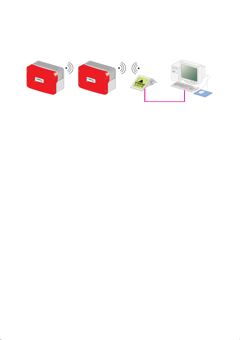
4. 2 Communication via Bluetooth
Requirements
Bluetooth is integrated as standard in SB 4000TL-20/5000TL-20. The PC or laptop must be
equipped with Bluetooth. If Bluetooth is fitted, the range is usually of up to only 10 m. If a Bluetooth
stick is retrofitted, however, this range is greater; in the case of Bluetooth Class 1 it is up to 100 m.
Data cannot be sent to Sunny Portal.
If the data from SB 4000TL-20/5000TL-20 is queried via Bluetooth, it cannot be sent to
Sunny Portal.
• In order to be able to send the data from SB 4000TL-20/5000TL-20 to Sunny
Portal, it must be queried via RS485 communication.
Grid guard parameters in SB4000TL-20/5000TL-20 via Bluetooth.
If the SB4000TL-20/5000TL-20 is connected with Sunny Data Control via Bluetooth, the
SMA grid guard parameter can be set using the padlock icon at the top right on the
"Parameters" page.
Commissioning
The commissioning of Bluetooth communication is described in chapter 8.3. 1 "Bluetooth" (Page 39).
Data Gathering
Chapter 11. 4 "Direct Data Acquisition from an Inverter" (Page 77) describes how to acquire and
save data from an inverter connected directly to the PC, and how to send these to Sunny Portal.
4. 3 Connection via RS485 and an interface converter
Requirements
The inverter must be equipped with a RS485 Piggy-Back. The I-7561 interface converter from
RS485 to USB is needed for connection to the PC via RS485 (SMA order number: I-7561), see also
chapter 5. 1 "Notes on the Use of Level Converters" (Page 20).
Connection
Information on this connection is provided in the I-7561 installation guide.
Data Gathering
Chapter 11. 4 "Direct Data Acquisition from an Inverter" (Page 77) describes how to acquire and
save data from an inverter connected directly to the PC, and how to send these to Sunny Portal.
16 SDC-TEN081450 Technical Description
Page 15
Connecting the PC to a Communication Device SMA Technologie AG
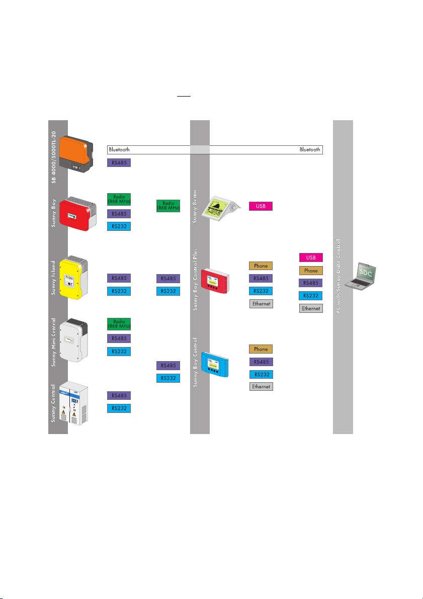
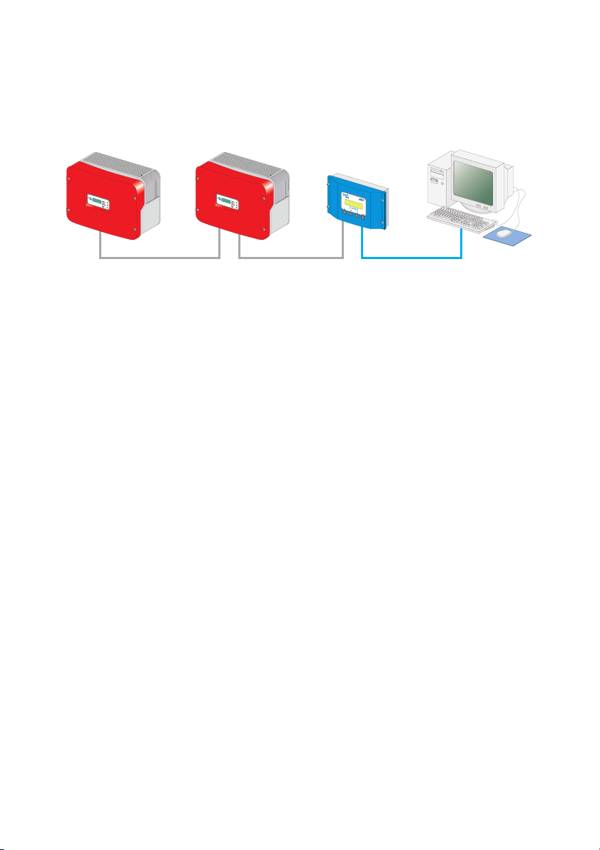
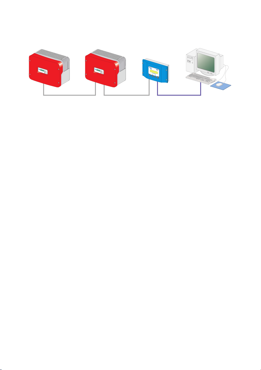
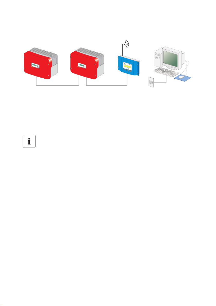
5 Connecting the PC to a Communication Device
In order to connect several inverters to the PC there are various communication devices at your
disposal. It is only ever possible to have one
as well as between the inverters.
single type of connection to the communication device,
RS232 is a 1:1 connection with which only one inverter can be connected to only one
communication device.
Technical Description SDC-TEN081450 17
Page 16
Connecting the PC to a Communication Device SMA Technologie AG
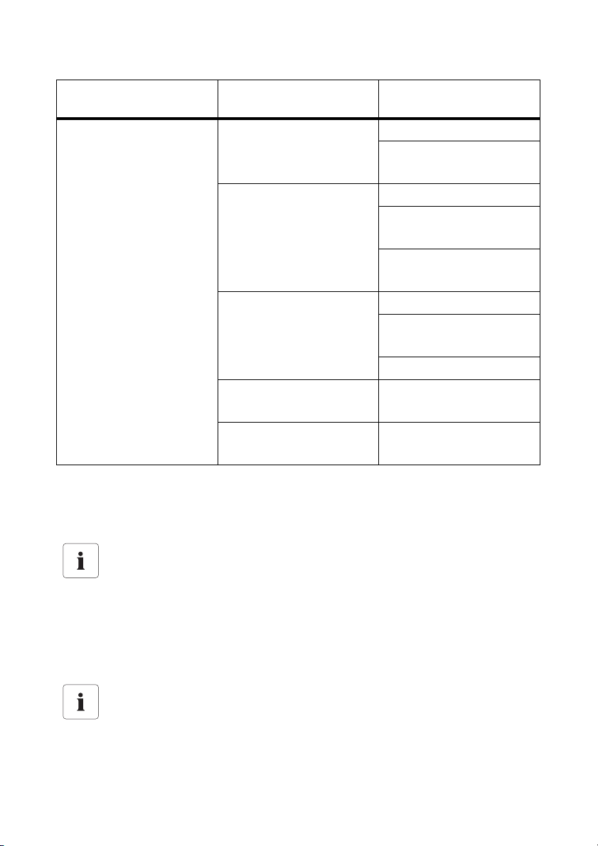
The following table shows the communication devices and the possible connection types.
Communication device Interface of
PC's interface
the communication device
Sunny Boy Control / Plus RS232 Piggy-Back RS232 connection
Interface converter
RS232 to USB
RS485 Piggy-Back RS485 connection
Interface converter
RS485 to USB
Interface converter
RS485 to RS232
NET Piggy-Back
with an analog modem
analog modem
ISDN Modem
(with a CAPI driver)
GSM Modem
NET Piggy-Back
ISDN Modem
with an ISDN modem
NET Piggy-Back
with a GSM modem
analog modem
ISDN Modem
(with a CAPI driver)
GSM Modem
NET Piggy-Back
Ethernet network card
with Ethernet
Sunny Beam USB USB connection
18 SDC-TEN081450 Technical Description
Page 17
Connecting the PC to a Communication Device SMA Technologie AG
Communication device Interface of
PC's interface
the communication device
Sunny Central Control RS232 Piggy-Back RS232 connection
Interface converter
RS232 to USB
RS485 Piggy-Back RS485 connection
Interface converter
RS485 to USB
Interface converter
RS485 to RS232
NET Piggy-Back
with an analog modem
analog modem
ISDN Modem
(with a CAPI driver)
GSM Modem
NET Piggy-Back
ISDN Modem
with an ISDN modem
NET Piggy-Back
Ethernet network card
with Ethernet
The following sections describe the various options for connection of the communication devices,
provide recommendations for cabling, and include wiring diagrams.
Information on the Sunny Central Control
Timeout settings for the Sunny Central Control.
For a Sunny Central Control, certain timeout settings have to be configured in the Sunny
Data Control software versions 3.5, or later.
• Configure these settings as described in chapter 13.12. 1 "Settings for the Sunny
Central Control" (Page 149).
This manual is also valid for the Sunny Central Control.
The Sunny Central Control is a variant of the Sunny Boy Control which is built directly into
the Sunny Central. Throughout this manual, only the Sunny Boy Control is mentioned. All
sections which apply to the Sunny Boy Control also apply to the Sunny Central Control.
Technical Description SDC-TEN081450 19
Page 18

Connecting the PC to a Communication Device SMA Technologie AG
5. 1 Notes on the Use of Level Converters
Interface converters are devices which convert data from one signal type to another, for instance,
from RS485 to USB. With the aid of these interface converters, a Sunny Boy Control/Plus can be
connected to a PC which does not have the appropriate interface.
Compatibility with interface converters
Compatibility with all level converters available on the market cannot be guaranteed.
SMA offers the following interface converters. These interface converters have been
tested and work with the Sunny Boy Control/Plus.
• RS232/RS485 to USB
- SMA order number: I-7561
• RS485 to RS232
- SMA order number: I-7520
20 SDC-TEN081450 Technical Description
Page 19
Connecting the PC to a Communication Device SMA Technologie AG
5. 2 Sunny Boy Control / Plus
5.2. 1 Connection via RS232
RS232
RS232 communication characteristics:
• A maximum of one Sunny Boy Control / Plus can be connected to a PC.
• The PC must be equipped with an RS232 port. If it is not, please read section 5. 1 "Notes on
the Use of Level Converters" (Page 20).
• The Sunny Boy Control / Plus requires an RS232 Piggy-Back at the PC (COM 2) port.
Alternatively, at the Sunny Boy Control Plus, the AUX (COM 3) port can be used, if this is
equipped with an RS232 Piggy-Back.
• The maximum total cable length is 12 m.
Cabling Recommendations
The connection between the Sunny Boy Control and the PC occurs by means of a commercially
available null modem cable. Use the null modem cable provided.
If the length proves insufficient, use a commercially available null modem cable of the required
length.
Jumper Functions at the Sunny Boy Control / Plus
With RS232 communication, no jumper must be mounted on the Sunny Boy Control / Plus at the PC
(COM 2) port, or on the Sunny Boy Control Plus at the AUX (COM 3) port.
Technical Description SDC-TEN081450 21
Page 20
Connecting the PC to a Communication Device SMA Technologie AG
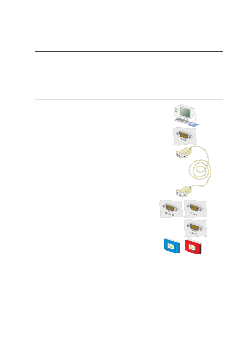
Wiring Diagram
PC
1.
2. Use the null modem cable provided, or a commercially
available null modem cable of the required length.
3. Plug the 9-pin D-Sub female connector into a free COM
port on your PC.
4. Lay the cable properly so that there is no risk of persons
tripping over it.
NOTICE!
Possible damage to the COM interfaces of the Sunny Boy Control / Plus and
the PC.
The COM interfaces of both devices could be damaged if the PC is turned on and
then the devices are connected to one another.
• Switch off PC
Sunny Boy Control / Plus
5. Plug the 9-pin D-Sub female connector into the port on
the Sunny Boy Control which is equipped with the
RS232 interface.
(A) Sunny Boy Control: PC (COM 2)
(B) Sunny Boy Control Plus: PC (COM 2) or AUX
(COM 3)
Jumper
6. Remove any jumpers A, B or C which may be plugged,
from the interfaces used.
AB
22 SDC-TEN081450 Technical Description
Page 21
Connecting the PC to a Communication Device SMA Technologie AG
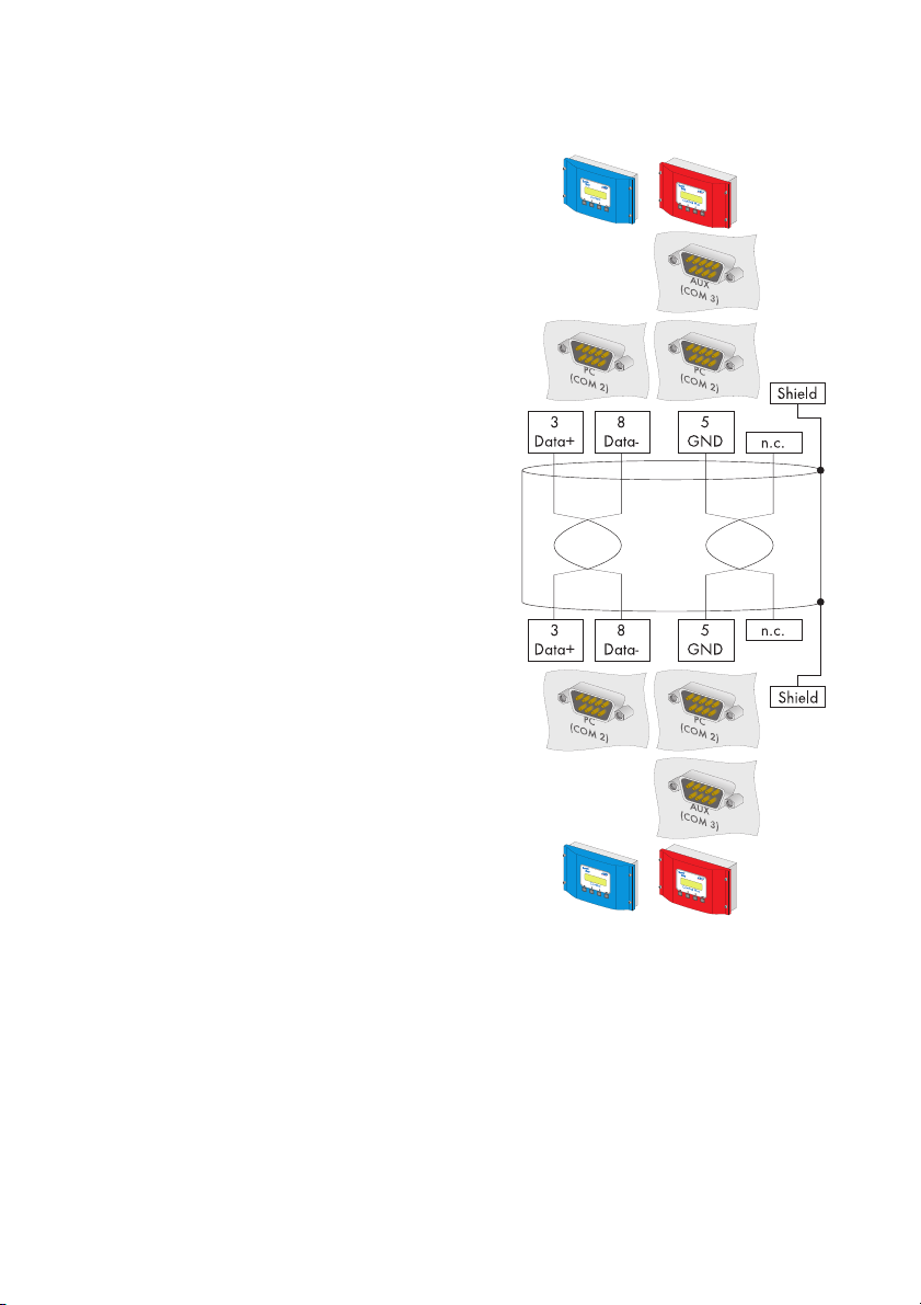
5.2. 2 Connection via RS485
RS485
RS485 communication characteristics:
• Up to 50 Sunny Boy Control / Plus devices can be connected to a PC.
• The PC must be equipped with an RS485 port. If it is not, please read section 5. 1 "Notes on
the Use of Level Converters" (Page 20).
• Each Sunny Boy Control requires an RS485 Piggy-Back at the PC (COM 2) port.
Alternatively, at the Sunny Boy Control Plus, the AUX (COM 3) port can be used, if this is
equipped with an RS485 Piggy-Back.
• The maximum total cable length is 1200 m.
Cabling Recommendations
The cable length and quality affect the signal quality. Observe the following indications in order to
achieve good signal quality.
• Use metallic D-Sub female connectors. Female connectors made of plastic, or metallized
plastic, can cause faulty data transfer.
• For the outdoors, use a communications cable with the following important properties.
- Cross-section: At least 2 x 2 x 0,22 mm
-shielded
- Twisted pair cables
-UV resistant
We recommend the following cable types for the outdoors.
SMA communications cable: COMCAB-OUTxxx*
*Available in the following lengths: xxx = 100 m/200 m/500 m and 1000
Lappkabel cables: UNITRONIC Li2YCYv 2 x 2 x 0.22 mm
2
, and at least 2 x 2 x AWG 24
2
You can use an indoor cable for the outdoors as well, provided you protect it from UV
radiation with the proper cable duct.
Technical Description SDC-TEN081450 23
Page 22
Connecting the PC to a Communication Device SMA Technologie AG
• We recommend the following cable types for indoors.
SMA communications cable: COMCAB-INxxx*
*Available in the following lengths: xxx = 100 m/200 m/500 m and 1000
Lappkabel cables: UNITRONIC Li2YCY (TP) 2 x 2 x 0.22 mm
2
Helukabel cables: PAAR-TRONIC-Li-2YCY 2 x 2 x 0,22 mm2
Pin Assignment of the Connection Cable
Sunny Boy Control PC
Signal Pin Pin Signal
Data + 3 Data +
Data - 8 Data -
GND 5 GND
Jumper functions
Termination
To increase the signal quality of the RS485 data bus, it must be terminated at both ends. Each
termination is made with a 120 W resistor between the two data lines. Terminate the last Sunny
Boy Control / Plus by means of a jumper. The position of the jumper is described in the user manual
of the Sunny Boy Control / Plus.
Signal biasing
To increase the signal quality of the RS485 data bus, a maximum of one bias can be connected in
the data bus. We recommend connecting the bias at the PC.
24 SDC-TEN081450 Technical Description
Page 23
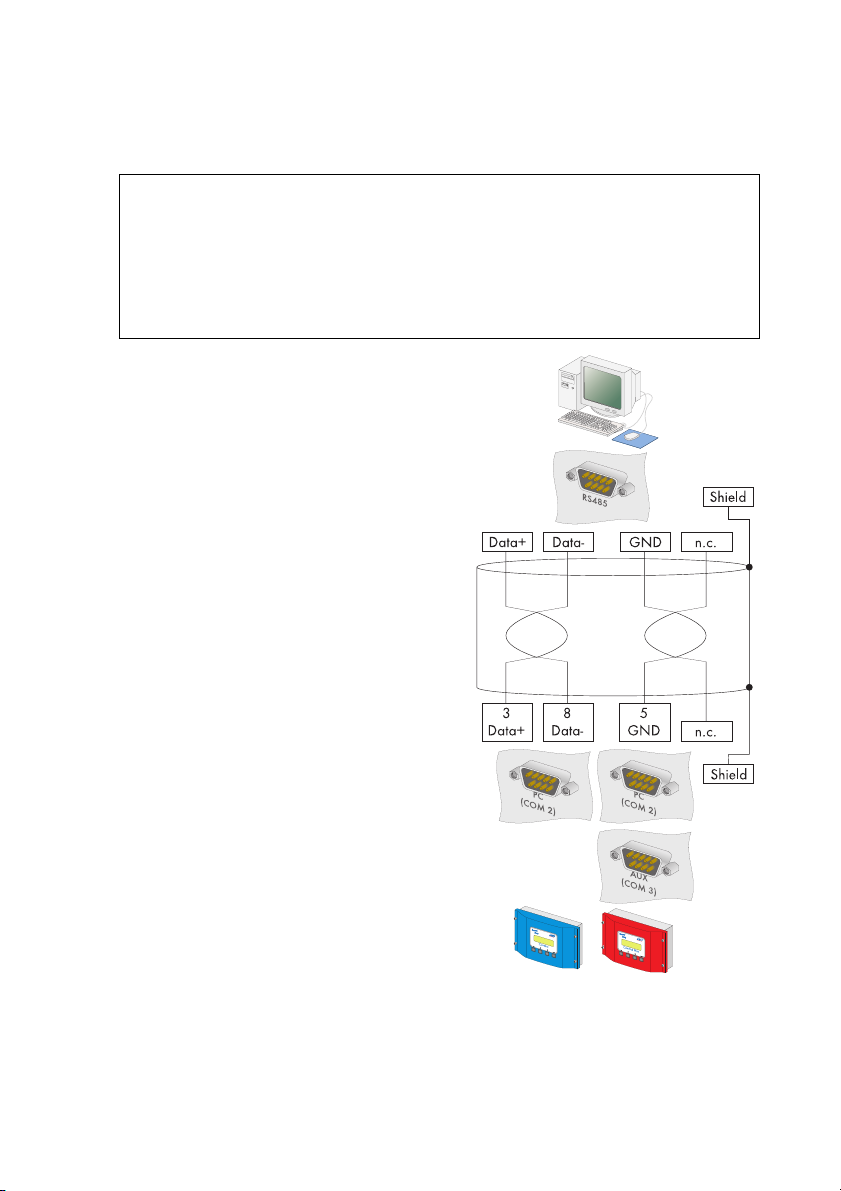
Connecting the PC to a Communication Device SMA Technologie AG
Wiring Diagram
PC
1.
2. Plug the 9-pin D-Sub female connector into a
free COM port on your PC.
For the pin assignment of the RS485 connection,
please refer to the PC's documentation, or the
plug-in card's documentation.
Data+ and Data– leads must be a twisted pair.
3. Shorten the wire of the fourth, unused conductor,
so that short circuits cannot arise.
4. Note down the wire color:
Data + ____________________
Data - ____________________
GND ____________________
NOTICE!
Possible damage to the COM interfaces of the Sunny Boy Control/Plus and
the PC.
The COM interfaces of both devices could be damaged if the PC is turned on and
then the devices are connected to one another.
• Switch off PC
Termination
5. Only if the PC is at one end of the 485 data bus:
Terminate the end of the cable as described in
the instructions for the PC or the plug-in card.
Signal biasing
6. Configure the RS485 data bus' bias as
described in the PC's documentation, or the
plug-in card's documentation.
7. Lay the cable properly so that there is no risk of
persons tripping over it.
Technical Description SDC-TEN081450 25
Page 24
Connecting the PC to a Communication Device SMA Technologie AG
Sunny Boy Control / Plus
8. Plug the 9-pin D-Sub female connector into the
port on the Sunny Boy Control which is
equipped with the RS485 interface.
(A) Sunny Boy Control: PC (COM 2)
(B) Sunny Boy Control Plus: PC (COM 2) or
AUX (COM 3)
9. Connect the PC's Data+ with the Data+ of the
Sunny Boy Control / Plus, and so on. The 3
connections should be made directly.
Use listed cable colors.
Termination
10. On the last Sunny Boy Control / Plus in the 485
data bus, Jumper A should be plugged into the
interface being used.
11. Jumper A must not be plugged into the used
interface on any of the other
Sunny Boy Control / Plus devices.
12. Remove any jumpers A, B or C which may be
plugged, from the interfaces used.
AB
AB
26 SDC-TEN081450 Technical Description
Page 25

Connecting the PC to a Communication Device SMA Technologie AG
5.2. 3 Connection via the Analog Modem NET Piggy-Back
Analog Modem Communication Characteristics
• As the connection to the Sunny Boy Control / Plus is established via the telephone network, it
is only ever possible to connect one Sunny Boy Control / Plus with the PC.
• The PC must be equipped with a modem (analog, ISDN with CAPI driver or GSM).
• The Sunny Boy Control / Plus requires an "analog modem" version of the NET Piggy-Back.
Compatibility with all PC modems available on the market cannot be
guaranteed.
Connection
1. Connect the PC to the telephone network, as described in the modem instructions.
2. Connect the Sunny Boy Control / Plus to the telephone network, as described in the
instructions for the Net Piggy-Back.
3. Use the software provided with the PC operating system to establish the connection between
the two devices.
Technical Description SDC-TEN081450 27
Page 26
Connecting the PC to a Communication Device SMA Technologie AG
5.2. 4 Connection via the ISDN NET Piggy-Back
ISDN Modem Communication Characteristics
• As the connection to the Sunny Boy Control / Plus is established via the telephone network, it
is only ever possible to connect one Sunny Boy Control / Plus with the PC.
• The PC must be equipped with an ISDN modem.
• The Sunny Boy Control / Plus requires an "ISDN" version of the NET Piggy-Back.
Compatibility with all PC modems available on the market cannot be
guaranteed.
Connection
1. Connect the PC to the telephone network, as described in the modem instructions.
2. Connect the Sunny Boy Control / Plus to the telephone network, as described in the
instructions for the Net Piggy-Back.
3. Use the software provided with the PC operating system to establish the connection between
the two devices.
28 SDC-TEN081450 Technical Description
Page 27
Connecting the PC to a Communication Device SMA Technologie AG
5.2. 5 Connection via the GSM NET Piggy-Back
GSM Modem Communication Characteristics
• As the connection to the Sunny Boy Control / Plus is established via the telephone network, it
is only ever possible to connect one Sunny Boy Control / Plus with the PC.
• The PC must be equipped with a modem (analog, ISDN with CAPI driver or GSM).
• The Sunny Boy Control / Plus requires a "GSM" version of the NET Piggy-Back.
Compatibility with all PC modems available on the market cannot be
guaranteed.
Connection
1. Connect the PC to the telephone network, as described in the modem instructions.
2. Connect the Sunny Boy Control / Plus to the telephone network, as described in the
instructions for the Net Piggy-Back.
3. Use the software provided with the PC operating system to establish the connection between
the two devices.
Technical Description SDC-TEN081450 29
Page 28
Connecting the PC to a Communication Device SMA Technologie AG
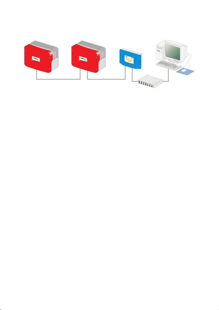
5.2. 6 Connection via the Ethernet NET Piggy-Back
Router or hub
Ethernet Network Communication Characteristics
• Any number of Sunny Boy Control / Plus devices can be connected to a PC via the Ethernet
network. The only limitation is the capability of the PC, whereby the main memory is the limiting
factor.
• A Sunny Boy Control / Plus can be connected directly to a PC.
• The PC must be equipped with an Ethernet network card.
• Each Sunny Boy Control / Plus requires an "Ethernet" version of the NET Piggy-Back.
Cabling Recommendations
The cable length and quality can adversely affect the signal quality. To achieve good results,
observe the following instructions.
• For the connection to a hub or router, you require a patch cable.
For the direct connection to a PC, you require a crossover cable.
• Use high quality cable, at least category 5 (SFTP Cat 5) or higher shielded twisted pair cable.
• The maximum permitted cable length for Ethernet cable is 100 m.
Connection to an Ethernet Network
1. Connect the PC to the network as described in the Ethernet network card's user manual.
2. Connect the Sunny Boy Control / Plus to the telephone network, as described in the
instructions for the Net Piggy-Back.
Direct Connection to a Single PC
1. Plug one end of the crossover cable into the PC's Ethernet network card.
2. Plug the other end of the Ethernet network cable into the NET socket of the
Sunny Boy Control / Plus.
3. Lay the cable properly so that there is no risk of persons tripping over it.
30 SDC-TEN081450 Technical Description
Page 29
Connecting the PC to a Communication Device SMA Technologie AG
5. 3 Sunny Beam
5.3. 1 Connection via USB
USB
USB Communication Characteristics
• A maximum of one Sunny Beam can be connected to a PC.
• The PC must be equipped with a USB port.
• The maximum total cable length is 3 m.
Connection
1. Connect the Sunny Beam to the PC as described in the Sunny Beam manual.
Technical Description SDC-TEN081450 31
Page 30
Installation SMA Technologie AG
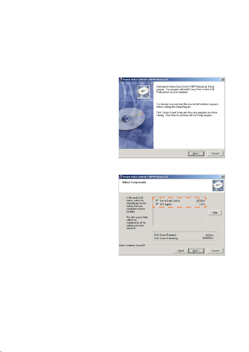
6 Installation
You can download Sunny Data Control from the download area at www.SMA.de or you can order
it as a CD.
6. 1 Installing Sunny Data Control
1. Switch on your PC and wait until the
operating system has booted up
completely.
2. Close any Windows programs which
may be open.
3. Start the Sunny Data Control
installation program. The Sunny Data
Control installation window opens
(see figure to the right).
4. Follow the installation program's
instructions.
SDC agent
You need the SDC Agent only if you also
intend to use Sunny Data Control for the
online presentation of your PV plant.
You do not need the SDC Agent for Sunny
Portal.
5. Place a check mark next to "SDC
Agent" in order to install it as well.
6. Once the installation is finished, you
can launch Sunny Data Control.
32 SDC-TEN081450 Technical Description
Page 31

Sunny Data Control User Interface SMA Technologie AG
7 Sunny Data Control User Interface
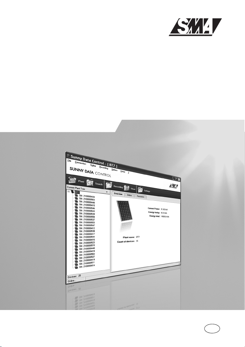
The Sunny Data Control user interface comprises three areas:
• (A) Menu Area
In the menu area you can access and use various Sunny Data Control functions by using the
menu bar. Using the symbols you can open the corresponding menu directly.
• (B) Plant diagram
The plant selected is displayed, along with its devices, which you have detected with Sunny
Data Control.
• (C) Display Area
In the display area you can display different views by selecting the appropriate tab.
-Overview
- Spot values (device overview)
- Parameter
- Channel recording (is shown once the devices have been detected).
A
B C
Technical Description SDC-TEN081450 33
Page 32

Sunny Data Control User Interface SMA Technologie AG
7. 1 Menu Area
The menu area comprises the menu bar (A1) and the icon bar (A2).
The most commonly used menus are also included as icons on the icon bar (A2), so they can be
accessed quickly.
A1
A2
(A1) Menu bar
The menu bar comprises six main menus:
•File
• Connection
•Spot values
• Continuous data recording.
Is only shown if there are yet no devices listed in the plant diagram, or if only one inverter is
connected directly to the PC.
•Options
• Extras
• ? (Manual, Information)
(A2) Icon bar
The icon bar is made up of icons representing the menu items most commonly used.
•Plant
Also accessible in the menu area via "Options / Choose Plant".
• Search
Also accessible in the menu area via "Options / Device detection".
• Record or save
Record is shown if there are yet no devices listed on the plant diagram (no devices have been
detected) or if only one inverter is connected directly to the PC.
Save is shown as soon as there are devices listed on the plant diagram (devices have been
detected).
•Show
•Settings
Also accessible in the menu area via "Options/Settings".
34 SDC-TEN081450 Technical Description
Page 33

Sunny Data Control User Interface SMA Technologie AG
7. 2 Plant tree
The plant selected is displayed, along with its devices, which you have detected with Sunny Data
Control.
Using the plant diagram menu here (see illustration) you can, for example, access information about
the selected device or delete it and add, arrange or substitute devices.
Some of the actions which you can select in the plant tree menu apply to the currently selected
device, while other actions apply to all devices.
If you call up the plant tree menu via the icon, you must first highlight the respective device by
clicking on the device's name.
Expanding and Collapsing the Plant Tree
By clicking on the nodes (+/- symbols), you can expand and collapse parts of the plant diagram.
This function facilitates the overview of a plant with many devices.
Technical Description SDC-TEN081450 35
Page 34

Sunny Data Control User Interface SMA Technologie AG
7. 3 Display Area
In the display area you can call up different pages by using the tabs (A).
-Overview
- Spot values (device overview)
- Parameter
- Channel recording (is shown once the devices have been detected).
A
B
When the "Spot values" page is shown, you can call up the task menu (B).
You can open up the task menu (B) by clicking on the icon to the right, or by right-clicking on
the respective device's field. Some of the actions you can choose in the plant diagram menu
apply only to the device selected and others apply to all.
36 SDC-TEN081450 Technical Description
Page 35

Initial Settings SMA Technologie AG
8 Initial Settings
8. 1 Creating Plants
By default, a plant with the name "My Plant" is always created automatically by Sunny Data Control
during installation. You can change the plant name which is displayed in Sunny Data Control, create
additional plants, or delete plants.
Sunny Data Control can only display one plant at a time (current plant). If you manage several
plants, you must first load each respective plant (see section 8. 2 "Loading a Plant" (Page 38)).
Detected devices and settings, such as the communication connection or parameters, always refer
to the respective plant, and are saved as settings for the respective plant.
8.1. 1 Changing Plant Names, Creating / Deleting Plants
Changing the Plant Name
1. "Options/Choose plant"
The "PV Plant" window opens.
2. Select "My PV plant".
3. Click on <Rename>. The name of the selected plant can now be written over.
4. Type in the desired name for the plant.
5. Click on <Close>.
Technical Description SDC-TEN081450 37
Page 36

Initial Settings SMA Technologie AG
Create new plant
1. Select "Options/Choose plant".
The "PV Plant" window opens.
2. Click on <New>.
3. Type in the desired name for the plant.
4. Click on <Close>.
Deleting Plants
Directions for deletion
If you delete a plant, the entire plant is deleted, along with all settings and detected
devices! The saved Excel and CSV files are retained.
1. Select "Options/Choose plant".
The "PV Plant" window opens.
2. Select the plant to be deleted.
3. If the selected plant, along with all settings and detected devices, is to be deleted immediately,
click on <Delete>.
4. Click on <Close>.
8. 2 Loading a Plant
If you have created more than one plant, you must first load the plant which you wish to edit or
display. Sunny Data Control can only display one plant at a time (current plant).
1. Select "Options/Choose plant".
The "PV Plant" window opens.
2. Select the plant to be loaded.
3. Click on <Load>.
38 SDC-TEN081450 Technical Description
Page 37

Initial Settings SMA Technologie AG
8. 3 Setting the Communication Connection
One must set the connection in Sunny Data Control according to the type of connection to the PC
which has been chosen.
The communication connection setting always refers to the current plant, and can be set differently
for each plant.
In Sunny Data Control, you can set the connections listed below, which are described in the sections
which follow.
• Bluetooth
See chapter 8.3. 1 "Bluetooth" (Page 39)
• COM1, 2, 3 etc.
(Your PC's COM ports are listed here: COM 1 , COM 2 , etc.)
See chapter 8.3. 2 "COM1 – COM255" (Page 43)
• Modem
(the type of modem installed at your PC is displayed here)
See chapter 8.3. 3 "Modem" (Page 44)
•Network
See chapter 8.3. 4 "Network" (Page 45)
• Sunny Beam (USB)
See chapter 8.3. 5 "Sunny Beam (USB)" (Page 47)
8.3. 1 Bluetooth
Notice regarding Bluetooth stick software.
Do not install the software included with the Bluetooth stick for the time being.
Requirements
• PC or laptop with integrated Bluetooth (range of usually only up to 10 m).
Alternative: USB Bluetooth stick (range of Class 1 Bluetooth stick is of up to 100 m).
• A Bluetooth ID of 1 or greater must be set at the inverters.
- ID = 1: Inverters cannot be networked, only inverters within reception range will be
detected.
- ID > 1: Inverters are networked, allowing all networked inverters to be detected.
Technical Description SDC-TEN081450 39
Page 38

Initial Settings SMA Technologie AG
Commissioning of Bluetooth communications.
1. Close the Sunny Data Control.
2. If the Bluetooth capability integrated into the PC is not to be used, disconnect it as described
in the PC instructions.
3. Plug the Bluetooth stick into the PC. Do not install the software included with the Bluetooth stick
for the time being.
The PC will check to see whether the Bluetooth stick can be installed automatically, and carries
out one of the following actions:
• Automatic installation begins, the PC installs the Bluetooth stick and reports that the new
hardware can be used. No CD is needed.
- Continue with step 4.
• The Hardware Assistant window opens, because installation requires a CD.
- Choose "No, not this time". Choose <continue>.
- Insert the CD included with the Bluetooth stick.
- Choose "Install software from a list or a specific source (advanced user)".
- Choose <continue>. The Bluetooh stick will be installed.
- Search for devices.
- The Bluetooth software shows the inverters' "Friendly names". For example:
SMA0003dSN: 2100000439 SN2100000439. The Bluetooth ID is displayed after
"SMA" (here: SMA0003 is ID 3).
- Choose a device which has the desired Bluetooth ID.
- Set up the virtual COM port as described in the Bluetooth stick manual. The virtual COM
port will be set up for the chosen ID.
- Record or note the number of the virtual COM port set up. If the Bluetooth environment is
to have an "outgoing" as well as an "incoming" COM port, record or note the number of
the incoming COM port.
40 SDC-TEN081450 Technical Description
Page 39

Initial Settings SMA Technologie AG
- If the Bluetooth stick software allows it, configure the settings in such a way that a
connection is made only after the application starts.
- Continue with step 4.
4. Start Sunny Data Control.
5. Click on on the "Settings" icon.
The "Settings" window opens.
6. Select "Communication".
7. Choose "Bluetooth" from the drop-down list "Connection via".
8. Click on <Settings>.
9. Click on <Change>.
The window "Choice of Bluetooth connection" opens.
Technical Description SDC-TEN081450 41
Page 40

Initial Settings SMA Technologie AG
10. Choose the appropriate procedure according to the type of Bluetooth installation carried out.
Installation was possible without a CD. Installation was only possible with a CD.
• Choose "Bluetooth Network IDs" or
"Individual Bluetooth devices" (point-topoint connection) from the "Type of
display" drop-down menu.
• Choose "Bluetooth COM ports" from the
"Display type" drop-down menu.
• Choose the virtual COM-Port which was
set up and click on <Ok>.
• Click on <Search>.
The Bluetooth IDs of detected devices are
searched for and listed.
• Close the window with <Ok>.
• Choose the Bluetooth ID set at the inverter
and click on <Ok>.
• Close the window with <Ok>.
11. Detect devices as described in chapter 8. 4 "Detecting Devices" (Page 49).
42 SDC-TEN081450 Technical Description
Page 41

Initial Settings SMA Technologie AG
8.3. 2 COM1 – COM255
1. Choose "Options / Settings"
The "Settings" window opens.
2. Choose "Communication".
3. In the drop-down list "Connection by", select the COM port via which the Sunny Boy Control
is connected to your PC. The COM ports are labeled on your PC (1, 2, 3, etc.).
4. Click on <Settings>.
The connection settings window opens.
5. In the drop-down menu "Media type" choose the type of communication between the Sunny
Boy Control and the PC.
Notice regarding the FIFO buffer with RS485.
When using RS485 switch off the serial interfaces' FIFO buffers, as described in the
operating system manual.
Technical Description SDC-TEN081450 43
Page 42

Initial Settings SMA Technologie AG
Bits per second (Baudrate)
6. In the "Bits per second:" drop-down list, select the Baudrate.
- In the case of a connection via the USB service interface: 1200 Bits per second.
- If the Sunny Boy Control is connected to the PC via RS232, with a cable length under 15
m: 19,200 Bits per second.
7. Click on <Ok>.
Transport Protocol
Clicking on <More>, the drop-down menu for the transport protocol is shown.
You can leave the preset transport protocol "SMANet + SunnyNet (autom.)" as the setting. Further
details are described in chapter 8.3. 6 "Setting the Transport Protocol" (Page 48).
8. Click on <Ok>.
9. Detect devices as described in chapter 8. 4 "Detecting Devices" (Page 49).
8.3. 3 Modem
1. Choose "Options / Settings"
The "Settings" window opens.
2. Select "Communication".
3. Choose "Modem" from the drop-down menu "Connection via".
4. Click on <Settings>.
5. Enter the telephone number.
6. In the "Using transport protocol" drop-down list, select the appropriate transport protocol for
the connected device, as described in section 8.3. 6 "Setting the Transport Protocol" (Page
48).
7. Click on <Ok>.
8. Detect devices as described in chapter 8. 4 "Detecting Devices" (Page 49).
44 SDC-TEN081450 Technical Description
Page 43

Initial Settings SMA Technologie AG
8.3. 4 Network
1. Choose "Options / Settings"
The "Settings" window opens.
2. Select "Communication".
3. Choose "Network" from the drop-down list "Connection via".
4. Click on <Settings>.
The network settings window opens.
Local Network
5. If you wish to detect all devices which are connected to your local network, check "Access to
all devices in the local network..." .
6. If you wish to detect additional devices, click on <Add>.
The window for configuration of a new connection opens.
7. In the field, "IP address or DNS name" enter the IP address or the DNS name of the device to
be detected.
The default address of the Sunny Boy Control is: 10.170.170.
Technical Description SDC-TEN081450 45
Page 44

Initial Settings SMA Technologie AG
8. Click on <Ok>.
The IP address or DNS name of the device is displayed.
RAS Connection
You can access an external modem (if access to it has been enabled for you) via an RAS
connection, in order to query the data from Sunny Data Control on this connection. If you wish to
access an external modem from your PC, the RAS service must be installed and configured on your
PC, and on the PC which you wish to access.
1. Check the field "Use RAS".
The window for configuration of the RAS connection opens.
2. In the field "Connection name" enter a descriptive name for the connection which would make
it easily recongizable, for example, the name of the plant or a family name.
3. In the field "Telephone number", enter the telephone number of the modem (connection).
46 SDC-TEN081450 Technical Description
Page 45

Initial Settings SMA Technologie AG
4. Choose the connection from the drop-down menu "Connection via".
5. In the field "Username", enter username of the owner of the connection.
6. In the field "Password" enter the password given by the owner of the connection.
7. Click on <Test the connection> to test the connection settings.
8. Click on <Save> to save the settings. The new connection is in the field "Telephone entries".
9. Click on <Apply>. The "Current device connections" window is displayed once more.
10. In the "Using transport protocol" drop-down list, select the appropriate transport protocol for
the connected device, as described in section 8.3. 6 "Setting the Transport Protocol" (Page 48).
11. Click on <Ok>.
12. Detect devices as described in chapter 8. 4 "Detecting Devices" (Page 49).
8.3. 5 Sunny Beam (USB)
1. Choose "Options / Settings"
The "Settings" window opens.
2. Select "Communication".
3. Choose "Sunny Beam" from the drop-down list "Connection via".
4. If you wish to see which Sunny Beam devices are already detected, click on <Settings>.
5. Click on <Ok>.
6. Detect devices as described in chapter 8. 4 "Detecting Devices" (Page 49).
Technical Description SDC-TEN081450 47
Page 46

Initial Settings SMA Technologie AG
8.3. 6 Setting the Transport Protocol
1. Choose "Options / Settings"
The "Settings" window opens.
The transport protocol depends on the type of device connected to the PC.
If you are unsure which transport protocol to set, select "SMANet + SunnyNet (auto)". Sunny Data
Control then automatically searches for the correct transport protocol.
Communication Devices
• Sunny Boy Control / Plus
- The Sunny Boy Control can operate with either transport protocol. The default setting in the
Sunny Boy Control is SMA-Net. Select the transport protocol which is set in your Sunny Boy
Control.
•Sunny Beam
- Select "SMANet".
Inverter
• SMA-Net
- Sunny Boys of type SWR, version BFR 8.22, or later
- All Sunny Boys of type SB
- All Sunny Mini Centrals
- All Sunny Centrals
•Sunny-Net
- Sunny Boys of type SWR prior to version BFR 8.22
48 SDC-TEN081450 Technical Description
Page 47

Initial Settings SMA Technologie AG
8. 4 Detecting Devices
By default, Sunny Data Control detects the following communication devices: Sunny Beam without
inverters, Sunny Boy Control with the inverters to which it is connected, and an inverter connected
directly to the PC. If necessary, you can narrow the scope of detection, as described in section 8.4.
1 "Narrowing the Scope of Device Detection" (Page 50).
1. Choose "Options/Device detection" or click on the icon "Search".
The "Searching for plant devices" window opens.
2. Enter the number of devices to be searched for.
3. Click on <Ok>.
The detection process starts. The devices are searched for.
4. Wait for the search to end.
The window closes when the search has ended (see illustration above).
The devices detected are listed on the plant diagram.
Technical Description SDC-TEN081450 49
Page 48

Initial Settings SMA Technologie AG
8.4. 1 Narrowing the Scope of Device Detection
The scope of device detection can be limited to the communication devices and the inverters
connected to them, or to an inverter connected directly to the PC.
1. Choose "Options / Settings"
The "Settings" window opens.
2. Select "Misc“.
3. In the area "Device detection mode, searching for" choose the types of device to be detected
in the search.
4. Click on <Ok>.
5. Start the device detection process, as described in section 8. 4 "Detecting Devices" (Page 49).
50 SDC-TEN081450 Technical Description
Page 49

Setting Parameters (Installer) SMA Technologie AG
9 Setting Parameters (Installer)
Sunny Data Control makes it possible to set parameters for inverters and for the Sunny Boy Control,
in order to specify operating modes for individual devices. The type and scope of the displayed
parameters depend on the security level.
If you are logged in as an installer, you can set more parameters. The security level is set via the
menu item "Extras / Security Level". See section 13. 10 "Changing the Security Level (Installer
Password)." (Page 147).
DANGER!
Death hazard due to changes in the inverter's internal safety
specifications.
Unauthorized changes to the SMA grid guard parameters cancel the operating permit.
• Changes to the SMA grid guard parameters are to be made only with the express
permission of the grid operator.
Grid guard parameters in SB4000TL-20/5000TL-20 via Bluetooth.
If the SB4000TL-20/5000TL-20 is connected with Sunny Data Control via Bluetooth, the
SMA grid guard parameter can be set using the padlock icon at the top right on the
"Parameters" page.
The "Parameters" window shows the parameter list of the device currently selected from the plant
diagram. Some parameters serve merely as information regarding the factory settings, whereas
others are adjustable.
1. From the plant diagram, choose the device the parameters of which should be edited.
2. Open the tab "Parameters".
The device's current parameter list is queried and listed.
Only the channel names in black type can be changed.
Technical Description SDC-TEN081450 51
Page 50

Setting Parameters (Installer) SMA Technologie AG
3. Click on the channel to be edited.
The "New parameter value" window opens.
4. Enter the new parameter value or choose it (this depends on the parameter. The changes are
not applied immediately. The parameter changed is marked for transfer with a blue point and
bold type.
5. If the new parameter value is to be applied to all devices of the same type, check the field "For
all devices with same type".
6. Click on <Ok>.
The channel changed is marked.
Accept changes
7. To apply all changes click on <Apply> on the lower edge of the screen. If the changes are
accepted by all devices successfully, the markings (blue point, bold type) are deleted.
• Edit: Edit the selected channel (or double click).
• Update: Updates the channel list displayed.
• Apply: Applies all changes and sets the parameters in the devices.
• Abort: No changes are made.
52 SDC-TEN081450 Technical Description
Page 51

Displaying Data SMA Technologie AG
10 Displaying Data
Various options are at your disposal for the display of current operating data. In order to manage
the copious amounts of data which arise, you can combine these options according to the size of
your plant and your display requirements for clarity and informative value.
The following display options are available:
• (A) Device overview on the page "Spot values" with individual device fields (A1).
• (B) Individual device information
• (C) Total overview
A1
A
BC
You can assign each individual display mode to each selected measuring channel. In so doing, it is
also possible to assign several display modes to the same channel.
The following sections describe the individual steps necessary for the display of the present
operating data.
Technical Description SDC-TEN081450 53
Page 52

Displaying Data SMA Technologie AG
10. 1 Creating a Device Overview
The page "Spot values", on which the device overview is shown, provides a quick and informative
display of your entire plant's current operative state. You can see your plant's devices and their
operative states at a glance.
The "Spot values" page is subdivided into fields (see figure below). In each field a device can be
displayed.
You can create and save several device overviews for each plant. This function is useful, for
example, with plants which include many devices, because it provides a clearer overview, and
different data views can be saved (see section 10. 8 "Managing the Device Overviews" (Page 67)).
1. "Drag and drop" the device from the plant diagram onto the desired field on which the device
should be displayed.
Only one device per field, and each device only once.
You can only drag each device into the device overview once. You can only drop a
device into an empty field.
54 SDC-TEN081450 Technical Description
Page 53

Displaying Data SMA Technologie AG
2. If you have dragged a Sunny Boy Control into a field, a prompt window opens.
- Klick on <yes> to add all inverters corresponding to Sunny Boy Control as well.
- To add only the Sunny Boy control, click on <No>.
Depending on whether you clicked <Yes> or <No> in the prompt window, either just the Sunny Boy
Control, or the Sunny Boy Control with all of its inverters, are added to the "Spot values" page.
Repositioning the Fields
3. Drag and drop occupied fields onto the desired empty fields.
This enables you to represent the actual structure of your plant pictorially in the overview
display or to combine several devices in groups.
Technical Description SDC-TEN081450 55
Page 54

Displaying Data SMA Technologie AG
10.1. 1 Displaying or Concealing Devices
1. Right click on the device field.
The task menu opens.
• Select <Fade out devices>.
- To add only this device, click on <this device>.
- To add all devices, click on <all devices>.
- To add all devices of this type, click on <all of this type>.
• Choose <Fade in devices>.
- To fade out all devices, click on <all devices>.
- To fade out all devices of this type, click on <all of this type>.
56 SDC-TEN081450 Technical Description
Page 55

Displaying Data SMA Technologie AG
10.1. 2 Arranging the Fields
You can change the vertical and horizontal arrangement of the fields in the device overview.
1. Choose "Options / Settings"
2. Select "Spotvalue Request / Arrangement".
3. In the area "Arrangement of devices horizontally / vertically", enter the number of fields that
you wish to have displayed.
Maximum number of fields: 100 x 100.
Minimum number of fields: 1 x 1.
If you wish to increase the number of fields to such an extent that the devices which are
already displayed will no longer have sufficient space to be fully displayed in the new device
overview, the adjustment of scale is ignored.
10.1. 3 Show or Hide the Grid Lines
1. Choose "Options / Settings"
2. Select "Spotvalue Request / Arrangement".
3. In the "Grid lines" area, add or remove the check mark in the "visible" check box.
10.1. 4 Setting the Data Query Sequence
You can set the direction in which Sunny Data Control scans the devices as vertical or horizontal.
1. Choose "Options / Settings"
2. Select "Spotvalue Request / Arrangement".
3. Set the scanning direction in the drop-down menu "Scanning direction".
10.1. 5 Maximizing the Device Overview (Online Display)
You can display the device overview in an enlarged format, covering the entire screen.
1. Open the "Spotvalues" tab.
2. Right click on the page.
The task menu opens.
3. Select "Maximize online display“.
The device overview is shown in an enlarged format, covering the entire screen. The plant
diagram and the menu bar are concealed.
4. To reduce the size of the display again, right click on the page and choose "Minimize online
page".
Technical Description SDC-TEN081450 57
Page 56

Displaying Data SMA Technologie AG
10. 2 Choose the channels for spot value readings.
For each device, you can set up which spot values are to be displayed on the page "Spot values"
on the device field (A) and in the individual device information (B).
You can retrieve the individual device information by right-clicking on the desired device on the
page "Spot values", and choosing "individual device information (see also chapter10. 6 "Accessing
Individual Device Information" (Page 63)).
A
B
1. Right click on the device field on the page "Spot values".
The task menu opens.
2. Select "Channel selection for Spot value scan"
The window for setting the selected device's channels opens.
3. Under "Channel selection is valid for", select whether you wish to set the channel selection for
the selected device only, or for all devices of a particular type.
4. Use the arrow buttons to add or remove the desired channels for the respective spot value
queries. To select several channels, hold down the control key.
58 SDC-TEN081450 Technical Description
Page 57

Displaying Data SMA Technologie AG
10. 3 Setting the Performance Display
The individual device fields (A) can change color according to the devices' calculated capacity
utilization. The capacity utilization is calculated on the basis of one channel (default channel: Pac).
This channel and the value for 100% capacity utillization determine the color changes of the device
field during the spot value query.
You can change the channel, and specify the threshold channel value, which is to indicate that the
device is performing at 100 % capacity. The performance display can be defined for individual
devices, or for a device type.
A
1. Right click on the device field on the page "Spot values".
2. Select "Channel selection for Spot value scan"
The channel settings window opens.
3. Under "Channel selection is valid for", select whether the performance display applies to the
selected device only, or to all devices of a particular type.
4. In the "Available channels" list, select the channel whose performance is to be calculated and
reflected in the color changes of the device fields.
5. Add the selected channel to the "Performance view" area by using the arrow button ">".
6. In the field to the left of "= 100 %“, enter the value which is to represent 100 % capacity
utilization for this channel.
7. Click on <Apply>.
You can set the color scheme of the device fields as described in section 10. 5 "Changing the Color
Behavior of the Device Fields" (Page 62).
Technical Description SDC-TEN081450 59
Page 58

Displaying Data SMA Technologie AG
10. 4 Setting the Communication Quality
In the device overview, the icon in the upper left-hand corner of each device field indicates the
quality of communication from the device to the PC.
The following adjustments can be made:
• Changing the Icon
• Changing the Visualization of Communication Quality
1. Choose "Options / Settings"
The "Settings" window opens.
2. Select "Spotvalue Request / Communication Performance“.
3. In the drop-down menu "Device type", choose the type of device for which the settings should
be valid.
60 SDC-TEN081450 Technical Description
Page 59

Displaying Data SMA Technologie AG
Changing the Icon
4. Click on Change Icons. The "Bitmap Selection" window opens.
5. Select the desired icon, and use the arrow buttons to add it to the respective areas (see figure
to the right).
6. Click on <Ok>.
Changing the Visualization of Communication Quality
7. To specify when the changes are to occur, enter the threshold values in the area "Change in
visualization of the communication performance".
The higher value determines the boundary between "Good" and "Moderate", and the lower
value the boundary between "Moderate" and "Poor".
8. Click on <Ok>.
Technical Description SDC-TEN081450 61
Page 60

Displaying Data SMA Technologie AG
10. 5 Changing the Color Behavior of the Device Fields
1. Choose "Options / Settings"
2. Select "Spotvalue Request / Colored Representation".
3. Click on <Load Scale>.
The "Load Palette for Performance Display" window opens.
4. Select a color palette from the list, and click on <Open>.
To learn how to create your own color palette, see section 13. 6 "Creating a Color Palette for
Device Fields" (Page 142).
Changing the Text Color
You can define which of the displayed text colors is to be used until which threshold background
color is reached.
5. Move separation mark (see figure below)
62 SDC-TEN081450 Technical Description
Page 61

Displaying Data SMA Technologie AG
10. 6 Accessing Individual Device Information
1. Open the "Spotvalues" tab.
2. Right click on the device field on the page "Spot values".
3. Choose "Individual device information".
The information for the single device is displayed (see figure below).
The following data is shown in the header of the single device view:
•Device name
The predefined inverter type and the serial number are displayed here. If you change the
device name, this name is shown here instead (to change the device name, see section
13.2. 1 "Setting the Device Name and Device ID" (Page 139)).
• Serial number
The inverter's serial number is displayed here.
•Device type
The inverter's device type is displayed here.
• Field position.
The position of the device field is shown on the "Spot values" page.
• Transmission quality
Here, the inverter's transmission quality is indicated in percent, and with the words: good, bad.
Beneath the header is a list of the channel names and their values.
You can specify which channels are to be shown in the individual device information (see section
10. 2 "Choose the channels for spot value readings." (Page 58)).
Technical Description SDC-TEN081450 63
Page 62

Displaying Data SMA Technologie AG
10. 7 Configuring the Total Overview
The total overview provides you with a quick overview of your plant's present performance data.
The total overview is updated cyclically.
The following information is displayed:
• Total output at present (Pac)
• Total yield (E-total)
• Energy produced today (E-Today)
This can only be selected if a Sunny Boy Control is also selected as device type for the total
overview.
Selecting Device Types
Devices are only included in the total overview computation if they are shown on the "Spot values"
page and only if their device type has been selected for the total overview.
1. Choose "Options / Settings"
2. Select "Spot value Request / Total Overview".
3. Click on <Change> to select the device types for the computation of the total overview.
64 SDC-TEN081450 Technical Description
Page 63

Displaying Data SMA Technologie AG
The "Device Type Selection" window opens.
4. Select the desired device types and use the arrow buttons to copy them into the "Selected
device types" field or to move them using "drag and drop".
5. Click on <Ok>.
The "Settings" window is displayed once more.
Configuring the Total Overview Display
6. Check on the values which should be displayed (e.g., "Display total output", "Display energy
produced today").
7. Configuring the Total Overview Display
The following settings are possible.
• Text:
Here, you can type in a text for the display (e.g. "Pac" for the total output, and "E-total" for the
total yield).
• Unit:
Here, you can choose between the units W, kW and MW in the drop-down list.
•Format:
Here, you can set the number of decimal places with which the values are to be displayed (#
= no decimal places... #.### = three decimal places).
•Factor:
Here, you can enter a factor by which the calculated value is to be multiplied.
•Offset:
Here, you can enter a corrective value which is to be added to the calculated value.
Technical Description SDC-TEN081450 65
Page 64

Displaying Data SMA Technologie AG
8. Click on <Ok>.
Activate Total Overview
9. Select "Spot values / Activate Total Overview".
Alternatively, click on the "Spot values" page and choose Select "Spotvalues / Activate Total
Overview".
The total overview is shown.
You can make the window bigger or smaller. The font size adapts automatically.
Deactivate the total overview
If you wish to deactivate the total overview, simply close the total overview window.
66 SDC-TEN081450 Technical Description
Page 65

Displaying Data SMA Technologie AG
10. 8 Managing the Device Overviews
You can create several device overviews for each plant ("Spot values" page). The configuration
data, for example, the devices' channel selections, the size and arrangement of the overview
window, etc., are saved together with the device overview.
The task of completely setting up an overview window with several devices can in some cases be
highly complex. To ensure that this effort only needs to be made once, Sunny Data Control provides
you with the option of managing different device overviews.
As a preset, the overview named "Online00" is created. See figure below.
10.8. 1 Managing the Device Overviews
1. Select "Spotvalues / Overview Management".
The "Overview Management" window opens.
All device overviews which have already been created are shown in the "Available Overviews" list.
The device overview "Online00" is the default, and can be renamed.
You can load, save, rename and delete device overviews here.
Technical Description SDC-TEN081450 67
Page 66

Displaying Data SMA Technologie AG
10. 9 Activating / Deactivating Spot Value Querying
You can activate and deactivate the querying of spot values if at least one device is displayed in
the device overview.
1. Choose "Spot values/Spot value querying".
2. Select "Activate" or "Deactivate".
If spot value querying is active, the icon and border of the currently queried device will flash.
During spot value querying, the text shown below is displayed in the bar at the lower edge of the
screen.
68 SDC-TEN081450 Technical Description
Page 67

Managing Data and Saving Data Locally SMA Technologie AG
11 Managing Data and Saving Data Locally
With Sunny Data Control, plant data can be saved in Excel and/or CSV formats. The following
sections describe the storage of data in Excel format and in CSV format. If an inverter is connected
directly to the PC, the data can only be saved as CSV data (SUO format, SMA-Sunny Online). See
chapter 11. 4 "Direct Data Acquisition from an Inverter" (Page 77).
11. 1 Reading Out and Saving Data from Sunny Beam
In order to display the essential key data of a PV system, Sunny Beam has been developed as a
cordless tabletop device. Initially, there were no plans for the archiving of data. Thus, as indicated
below, the subsequent built-in possibility to record data using Sunny Data Control and Sunny Portal
is limited.
Data Archiving with Sunny Data Control
With the Sunny Beam, the data gathered from the entire plant during one month can be archived,
but not data from the individual inverters. As the values are only stored in Sunny Beam for one
month, you must read out the data with Sunny Data Control once a month.
Data Interval
E-day: read out once a month
Yield (EUR): read out once a month
CO2 avoided: read out once a month
Furthermore, Sunny Beam only saves the daily power output (Pac) for the present day. Once a new
day begins, the previous day's Pac data is erased. Thus, Pac data must be read out every evening.
Data Interval
Pac: read out every evening
(limited utilizability)
Archiving Data with Sunny Portal
With Sunny Data Control, the above-mentioned data can be transferred over to the Sunny Portal.
Because the E-total value can not be recorded using Sunny Beam, the use of this data with Sunny
Portal is restricted. Nevertheless, this is indispensable for some views using Sunny Portal. For this
reason, it only makes sense to graphically present Sunny Portal's daily energy values (E-day), the
avoided CO2 emissions and the yield (EUR) as a monthly overview.
The visualization of the daily output (Pac) is possible. Nevertheless, as already mentioned above,
the data must be read out nightly.
Technical Description SDC-TEN081450 69
Page 68

Managing Data and Saving Data Locally SMA Technologie AG
11. 2 Saving Data in Excel Format
Storage of data in Excel format is the default option, and can be activated and deactivated. The
data is saved in the directory in which Sunny Data Control was installed. The default directory is
"C:\Programs\SMA\Sunny Data Control\Plants“.
If you wish to save the data in Excel format, all that remains to be done is to select the channels
which are to be recorded. This is explained in section 11. 5 "Setting up Sunny Boy Control Channel
Recording" (Page 81).
Activating or Deactivating Data Storage in Excel Format
1. Choose "Options / Settings"
2. Select "Data Storage“.
3. Check on the field to the left of Excel, or remove the check, in order to switch the data storage
in Excel format on or off.
4. Click on <Ok>.
70 SDC-TEN081450 Technical Description
Page 69

Managing Data and Saving Data Locally SMA Technologie AG
11. 3 Saving Data in CSV Format
For storage of data in CSV format, various templates are at your disposal. The CSV files can also
be created in a user-defined manner. The following settings are user-definable:
• Storage location
• File names
• Number of rows of measured values
• Line break format
• Delimiter symbol (cell separator)
• Storage of measured values (which channel in which row, etc.)
• Time stamp from time of measurement
11.3. 1 Creating a New CSV Type
Instructions on changing a CSV-Type.
The settings for a created CSV type can no longer be altered once the first data have
been read and saved.
1. Choose "Options / Settings"
2. Select "Data Storage“.
3. Click on <+> to set a new CSV type.
Technical Description SDC-TEN081450 71
Page 70

Managing Data and Saving Data Locally SMA Technologie AG
The window for configuration of a new CSV type opens.
4. Type the desired name for the CSV type into the "Name" field.
5. The CSV data is stored in the following directory as a preset/default.
C:\Documents and Settings\“Name of User“\Application Data\SMA\Sunny Data
Control\Plants\“Plant name“\“CSV_1 etc.“
This directory is user-specific, and is set up automatically upon creation of a new CSV type. If
you wish to select a different directory, click on the folder icon.
Selecting a Template
6. Select a template in the "Template" field.
The templates have the following properties:
- SMA standard format: Everything freely selectable, except for the file's column header.
- SMA-Sunny Online (SUO):
Column header as in Excel / SUO files, predefined values, no column selection. Column
header as in Sunny Data.
- No column header:
No column header, predefined values, manual column selection.
- User-defined: Everything freely selectable.
72 SDC-TEN081450 Technical Description
Page 71

Managing Data and Saving Data Locally SMA Technologie AG
Insert Mode
Depending on which template you have selected, you can specify the method of insertion.
•fixed
The "fixed" mode is used when only certain channels are to be saved.
The columns are specified by the user. The selection of columns is set via the <Select columns>
button, as described in the next step.
• XY Diagram
In "autotinsert" mode, the channels which are set under "Channel recording" are saved.The
next section describes how to set the channels for channel recording. See section 11. 5
"Setting up Sunny Boy Control Channel Recording" (Page 81). The columns are inserted
automatically.
7. In the "Insert mode" field, select one of the two modes for writing measured values to CSV files.
Selecting Columns
Depending on which template you have selected, you can now select the columns.
8. Click on <Select columns...>.
The "Select columns" window opens.
9. In the "Column type" drop-down menu, choose a column type.
There are four column types:
- <empty> = column remains empty in the CSV file.
- Channel = allocation occurs via selection of a channel.
- Text = the entered text is written in the column.
- Timestamp = the date pattern from the combination field (combo box) is written as an
absolute date.
Technical Description SDC-TEN081450 73
Page 72

Managing Data and Saving Data Locally SMA Technologie AG
You can insert a new column above a highlighted column with <Insert>.
With <Delete>, you can delete the highlighted column.
With <New>, you can add a new column beneath all the other columns.
The order of the rows in the table can be changed using "drag and drop".
10. Set up the column types as desired.
11. Click on <Apply>.
The window for setting the CSV type is shown again.
74 SDC-TEN081450 Technical Description
Page 73

Managing Data and Saving Data Locally SMA Technologie AG
File Name
12. Click on <Details>.
13. Select the desired file name pattern from the "File pattern" list, or create your own pattern by
writing in the "File pattern" field.
In the "Example" area, you see an example of the respective selected file name pattern.
The structure of the file names comprises the input symbols listed below, and the file suffix
".csv".
- {DD} = stands for day (01 to 31 are displayed)
- {MM} = stands for month (01 to 12 are displayed)
- {YYYY} = stands for year (if {YY} is selected, the last two digits of the year are displayed,
e.g. "07“. If {YYYY} is selected, the year is shown in full, e.g. "2007“).
- {NN} = sequential number
- {hh} = stands for hour
- {mm} = stands for minute
- {ss} = stands for second
These input symbols must be between braces { }, so that the input symbols are translated into
their respective meanings (e.g. year), and thus the current year will appear at this position in
the file name (e.g. {YY} = 07 and {YYYY} = 2007).
The following additional input symbols are also permissible for the file names.
- _ (underscore)
-. (period)
- -- (hyphen)
Further Settings
If you have selected the template type "User defined" or "SMA-standard format", you can make the
following additional settings to the CSV files. The line break format can be set for all template types.
• Line break format
Choose the line break format for the PC operating system:
- „CRLF“ (0x0d 0x0a)= Windows
„LF“ (0x0a)= Mac
„CR“ (0x0d)= Unix
• Cell Delimiter:
- Select the desired cell delimiter symbol (semicolon, tab (tabulator), or space).
• Maximum number of lines
- Enter the desired maximum number of lines which are to be displayed in a CSV file. No
more than 16000 lines can be written.
• Column header type
- Select the desired column header type (only possible with the "User defined" template).
Technical Description SDC-TEN081450 75
Page 74

Managing Data and Saving Data Locally SMA Technologie AG
11.3. 2 Structure of the Standard CSV Format
Every CSV file contains a fixed file header, and a data block into which the measurement data is
written. The file header comprises 8 rows, and has the following structure:
Row 1 Version CSV1|Tool SDC|Linebreaks CR/LF|Delimiter semicolon|Decimalpoint
comma|Precision 3|Language en|Plant Plant-CSV-1|User zdw@SMA.de|
Row 2 empty
Row 3 device name 1 device name 1 device name 2 device name 2
Row 4 Device type Device type Device type Device type
Row 5 Serial number Serial number Serial number Serial number
Row 6 channel name1 channel name2channel name1 channel name
2
Row 7 channel type channel type channel type channel type
Row 8 time
stamp
format
Row 9 Date channel value channel value channel value channel value
Row... Date channel value channel value channel value channel value
Channel unit Channel unit Channel unit Channel unit
All attributes of the CSV format appear in row 1, separated by pipe symbols.
76 SDC-TEN081450 Technical Description
Page 75

Managing Data and Saving Data Locally SMA Technologie AG
11. 4 Direct Data Acquisition from an Inverter
This chapter describes how to acquire and save data from an inverter connected directly to the PC,
and how to send these to Sunny Portal. With a direct connection of a PC to an inverter, the data can
only be saved as CSV data (SUO format, SMA-Sunny Online).
Note on SB4000TL-20/5000TL-20 and Sunny Portal.
If the data from SB 4000TL-20/5000TL-20 is queried via Bluetooth, it cannot be sent to
Sunny Portal.
• To send the data to Sunny Portal, it must be queried via RS485 communication.
11.4. 1 Set data storage
The settings for the data storage of an inverter which is directly connected to the PC are described
below.
1. Choose "Continuous data recording/settings"
The "Settings" window opens.
2. Change the frequency with which data from the inverter should be queried in the field
"Request cycle". At the "User" security level this is preset at 30 seconds. At the "Installer"
security level this is preset at 15 seconds.
Technical Description SDC-TEN081450 77
Page 76

Managing Data and Saving Data Locally SMA Technologie AG
3. In the "Recording" area there are two options:
- "All values" = The channels are read at the query cycle intervals set and their values are
recorded in these intervals.
- "Average values" = The channels are read at the query cycle intervals set, but their values
are recorded at intervals set in the "Averaging over" drop-down menu. The average value
is communicated and recorded only over the analog channels (e.g., Pac, Fac, Uac). In all
other channels the values captured last are the ones recorded. This option can reduce the
amount of data considerably, without losing their significance.
4. In the area "Autostart", the user can set the start and stop times during which Sunny Data
Control should record all selected measurement channels.
Chapter 11.4. 2 describes how to start the data recording manually.
5. Click on <Settings>.
The window for setting the data storage opens.
6. In the field "Name" a name for the settings can be entered.
7. The data is stored in a user-specific directory by default:
C:\Documents and Settings\“Name of User“\Application Data\SMA\Sunny Data
Control\Plants\“Plant name".If you wish to select a different directory, click on the folder icon.
8. Click on <Select columns...>.
The "Select columns" window opens.
9. In the "Description" drop-down menu, select the date format with which the date should be
shown on the column.
78 SDC-TEN081450 Technical Description
Page 77

Managing Data and Saving Data Locally SMA Technologie AG
10. Click on <New>.
The column label "channel" is introduced.
You can insert a new column above a highlighted column with <Insert>.
With <Delete>, you can delete the highlighted column.
With <New>, you can add a new column beneath all the other columns.
11. Click on <...>.
The"Channel selection..." window opens.
If you are logged in as an installer, more channels are available to choose from.
12. You can add individual channels, or all of a node's channels together, via drag and drop or
witht the arrows.
13. Click on <Apply>.
The "Select columns" window is displayed once more.
14. You can add additional columns in the same manner if you so wish.
15. Click on <Apply>.
The window for setting the data storage opens again.
16. Click on <Details>.
Only the line wrap for the operating system can be set in the data storage for an inverter directly
connected to the PC.
The file name format is fixed to "YYMMDDNN.suo".
- {YYYY} = stands for year (if {YY} is selected, the last two digits of the year are displayed,
e.g. "07“. If {YYYY} is selected, the year is shown in full, e.g. "2007“).
- {MM} = stands for month (01 to 12 are displayed)
- {DD} = stands for day (01 to 31 are displayed)
- {NN} = sequential number
17. Choose the line break format for the PC operating system.
18. Click on <Apply>.
Technical Description SDC-TEN081450 79
Page 78

Managing Data and Saving Data Locally SMA Technologie AG
11.4. 2 Saving and Viewing Data
This chapter describes how to acquire and save data from an inverter connected directly to the PC.
The data can be saved only after you have set up the data storage as described in chapter 11.4. 1.
Begin Continuous Data Recording
1. Choose "Continuous data recording/Start" or click on the "Record" icon.
On the lower edge of the screen you can see how long the data recording has been running.
During data recording all menu items are deactivated, with the exception of "Data",
"Continuous data recording" and "Extras".
The "Record" icon becomes a "Stop" icon.
Stopping Continuous Data Recording.
2. If you want the data recording to stop, click on the "Stop" symbol, or choose "Data Recording/
Stop".
Viewing Data
3. Click on the "Show" icon.
The window for choosing the data opens.
4. Select the chosen data and click on "Open".
Excel starts.
5. Click on <Enable Macros>.
The data is listed on an Excel table.
You can read how to create a diagram based on the data in chapter 11. 8 "Creating a Chart
in Excel" (Page 92).
11.4. 3 Sending Data to Sunny Portal
How to send data to Sunny Portal is described starting on chapter 12. 3 "Configuring Sunny Portal
Mail" (Page 99).
Note on SB4000TL-20/5000TL-20 and Sunny Portal.
If the data from SB 4000TL-20/5000TL-20 is queried via Bluetooth, it cannot be sent to
Sunny Portal.
• To send the data to Sunny Portal, it must be queried via RS485 communication.
80 SDC-TEN081450 Technical Description
Page 79

Managing Data and Saving Data Locally SMA Technologie AG
11. 5 Setting up Sunny Boy Control Channel Recording
Starting with Sunny Data Control firmware 3.05.
The function "Channel recording" is only available for Sunny Boy Control devices with
firmware version 3.05, or later.
With Sunny Data Control, you can select channels which the Sunny Boy Control is to record. By
default, the Sunny Boy Control records the channels "Pac", "E-total" and "Upv" from the detected
inverters. With Sunny Data Control, you can then read out, save, and process the recorded
channels.
1. Open the tab "Parameters".
The "Channel recording" page is shown, and the devices' channel lists are loaded.
2. To call up a device's channels, click on the device in the plant diagram.
Technical Description SDC-TEN081450 81
Page 80

Managing Data and Saving Data Locally SMA Technologie AG
A list of the device's archive channels is displayed.
3. Click in the box next to the "End of recording" column for the respective channel
(under the symbol seen in the figure to the right), thus adding or removing a cross.
If a cross is added, the channel is recorded in the Sunny Boy Control.
The "commit" button appears.
4. Click on one of the <Commit> buttons to apply the new settings, and to transfer them to the
Sunny Boy Control.
Calling up newly recorded channels.
The first channel values of a newly recorded channel are only accessible after the Sunny
Boy Control's recording interval has passed. This is usually after 15 minutes.
82 SDC-TEN081450 Technical Description
Page 81

Managing Data and Saving Data Locally SMA Technologie AG
11. 6 Reading Out Data Saved on the Sunny Boy Control
The Sunny Boy Control records all channels which you have selected for channel recording (see
section 10. 2 "Choose the channels for spot value readings." (Page 58)).
By default, the Sunny Boy Control records the channels "Pac", "E-total" and "Upv" from the detected
inverters. The channels which you wish to read from the Sunny Boy Control must be first marked and
saved as described below.
Upon the first readout, Sunny Data Control saves all of the data recorded at the Sunny Boy Control,
i.e. the complete time range. Afterwards, only new data is read out and saved. How to reset the
time ranges, or to read out the entire time range, is described in sections 11.6. 3 "Resetting Time
Ranges" (Page 86) and 12. 2 "Reading Out the Complete Time Range" (Page 98).
1. Open the tab "Parameters".
The "Channel recording" page is shown, and the devices' channel lists are loaded.
2. To call up a device's channels, click on the device in the plant diagram.
Technical Description SDC-TEN081450 83
Page 82

Managing Data and Saving Data Locally SMA Technologie AG
A list of the device's archive channels is displayed.
3. In the "Channel query" column (under the icon seen in the figure to the right), in the
field next to the channel, click to place or remove a check mark. If a check mark is
added, the channel is marked to be saved.
4. Repeat this procedure for each device.
5. Click on the "Save" icon. The submenu opens.
6. If you wish to save all marked channels, click on "Download all marked archiv channels".
If you wish to save all energy channels, click on "Download all energy values".
Data transfer begins. This process can take several minutes, depending on the data volume.
84 SDC-TEN081450 Technical Description
Page 83

Managing Data and Saving Data Locally SMA Technologie AG
11.6. 1 Storage Time Refresh
Sunny Data Control displays the time ranges of newly recorded values from the communication
device which have not yet been read out (see figure below).
In Sunny Data Control, the time ranges update only when the program is started up. In case you
have kept Sunny Data Control open for a longer period of time, and wish to read out newly
recorded data, you must first update the time ranges.
1. Select "Options / Storage Time Refresh".
The time ranges update.
2. Read out the data as described in chapter 11. 6 "Reading Out Data Saved on the Sunny Boy
Control" (Page 83).
You can also set the time ranges which you wish to read out, as described in chapter 11.6. 2.
11.6. 2 Setting Time Ranges
With Sunny Data Control, you can set the readout time ranges of all channels, or of individual
channels.
1. Click on the chosen channels while holding down the Ctrl key.
2. Right click on a marked channel on the "Channel recording" page.
A menu opens.
3. Choose "Select channel time range".
Technical Description SDC-TEN081450 85
Page 84

Managing Data and Saving Data Locally SMA Technologie AG
4. Select "All channels" or "Selected channels only".
The window for setting the time range opens.
5. Click on the end or the beginning of the time range and drag it while holding down the mouse
button. The date of the new time range is displayed immediately.
6. Click on <Ok>.
11.6. 3 Resetting Time Ranges
This function is necessary if you also wish to read out data from the Sunny Boy Control which have
already been queried. Sunny Data Control keeps a record of the time ranges which have already
been read out from the Sunny Boy Control, and normally only queries new data. You can reset the
Sunny Data Control time ranges as follows:
1. Choose "Extras/Reset time ranges".
A security question is shown.
2. Confirm the prompt with <Yes> in order to reset the time ranges.
86 SDC-TEN081450 Technical Description
Page 85

Managing Data and Saving Data Locally SMA Technologie AG
11.6. 4 Structure of the Excel Files
Beispiel Dateien von Sunny Boy Control.
The structure of the Excel files is explained on the basis of files which have been read out
from a Sunny Boy Control. Files read out from a Sunny Beam have a similar structure.
The data is saved as Excel files on your PC in the respective plant's directory. The directory has the
name of the plant which you have created in Sunny Data Control.
By default, the plants' data is in the directory:
"C:\Dokumente und Einstellungen\<Benutzername>\Eigene Dateien\SMA\Sunny Data
Control\Plants".
If you have already saved plant data with earlier versions of Sunny Data Control, your directory
containing the plant data will continue to be used (C:\Programme\SMA\Sunny Data
Control\Plants).
If you selected a different directory on your PC during installation of Sunny Data Control, open the
directory in which Sunny Data Control is saved, and open the directory "Plants".
In the saved data, a distinction is made between measurement data and daily energy data. This
data is read out from the Sunny Boy Control separately, and is saved in separate files.
• Daily files are saved together in a consolidated yearly file.
• All other measured values are saved together in consolidated monthly files.
For each Sunny Boy Control, there is a subdirectory with a name which comprises the text "SBC"
and the device's serial number (e.g. SBC119010325).
This is where the files with the saved measurement data are situated. The measurement data from
the individual channels is sorted according to day, and is saved on a monthly basis in the
corresponding devices' subdirectories in separate Excel files.
Thus, the number of files is determined by the measurement period. For instance, if measurement
data was recorded over an entire year with the Sunny Boy Control, there would be twelve files with
monthly values on your hard drive after saving.
Technical Description SDC-TEN081450 87
Page 86

Managing Data and Saving Data Locally SMA Technologie AG
y
Monthly values
(SDM_YYMM.xls)
Year Month
Daily energy values
(SDT_YY.xls)
Year
Monthly values, if the measuring
interval is lower than 3 minutes
(SDM_YYMMDD.xls)
Year Month Day
Example of an Excel File
Channel access ke
Channel unit
Device name
(Device type/
Serial number).
Device ID
Device type
serial number)
Date and time of the
measurement
88 SDC-TEN081450 Technical Description
Selection of pages using
tabs.
Measured values
Page 87

Managing Data and Saving Data Locally SMA Technologie AG
11. 7 Configuring the Automatic Readout
The automatic readout can only be performed if both the PC and Sunny Data Control are on.
Use with Sunny Beam is limited.
With the Sunny Beam, the function "Automatic Readout" only makes sense if the Sunny
Beam is permanently connected to the PC with a USB cable.
With the automatic readout, data is automatically queried from the Sunny Boy Control at intervals
of a length which you define, and is saved in Sunny Data Control. Only the devices displayed on
the page "Spotvalues" are taken into account.
Spot value querying is not updated.
During the automatic readout, the spot value querying does not update until the readout
is complete. In the bar at the lower edge of the screen, you can see whether data is
currently being read out (see figure).
11.7. 1 Starting a New Task
1. Choose "Options / Settings"
2. Select "Automatic Readout".
3. Check "Active"
4. Click on <+>.
Technical Description SDC-TEN081450 89
Page 88

Managing Data and Saving Data Locally SMA Technologie AG
The window shown below opens.
5. Adjust the settings as desired.
•Name
In the "Name" field (see figure below), type in the desired name for the automatic readout task
(e.g. which plants the task involves).
•Auto Start
Here you can specify when the automatic query is to start.
Two possibilities are available.
- Once per day
Here, you can specify on which day of the week (or daily) and at what time of day the
automatic readout is to start.
- Cyclically
Here you can specify between what times and at what intervals (after how many minutes) the
automatic readout should begin.
6. In the "Plants" area select the plants to which these settings will apply.
(Click on the names of the plants in the "Available Plants" field, and add them to the "Assigned
Plants" field with the arrow button ">").
7. Click on <Apply>.
90 SDC-TEN081450 Technical Description
Page 89

Managing Data and Saving Data Locally SMA Technologie AG
The "Settings" window opens again.
The name of the task which has been set and the start time are shown in the window.
8. Click on <Ok>.
11.7. 2 Editing / Deleting a Task
1. Choose "Options / Settings"
The "Settings" window opens.
2. Select "Automatic Readout".
3. Click on the name of the task to be edited.
4. Edit the task:
• Click on < -- > to delete the task immediately.
• To edit the task, click on <Settings>.
The window for setting the task opens.
Adjust the settings as desired.
5. Click on <Ok>.
11.7. 3 Deactivating the Automatic Readout
1. Choose "Options / Settings"
The "Settings" window opens.
2. Select "Automatic Readout".
3. Uncheck "Active".
4. Click on <Ok>.
Technical Description SDC-TEN081450 91
Page 90

Managing Data and Saving Data Locally SMA Technologie AG
11. 8 Creating a Chart in Excel
Your recorded measured values can easily be analyzed graphically with Excel. The data is also
automatically visualized in a chart.
To this end, there are two options, which are described in the next sections.
• Automatic analysis:
The analysis is started via Sunny Data Control. Excel opens automatically with the data
analysis macro.
• Manual analysis:
Manual anal ysis is only required if you wis h to sta rt the a nalysis on a PC on which S unny Data
Control is not installed. The analysis is then started directly from Excel, and the macro is
executed manually.
92 SDC-TEN081450 Technical Description
Page 91

Managing Data and Saving Data Locally SMA Technologie AG
11.8. 1 Automatic Analysis
The automatic analysis is started in Sunny Data Control. Excel opens automatically with the macro
which has been specially written for the analysis.
1. Click on the "Show" icon.
The submenu opens.
2. Select "Excel files", or the CSV type which you have created for saving CSV files (see section
11. 3 "Saving Data in CSV Format" (Page 71)).
The window for choosing the data opens.
3. Select the desired plant. By default, the current plant is always displayed.
4. Open the directory of the chosen device.
5. Open the Excel file which contains the data that you wish to analyze.
Excel launches automatically, and a confirmation prompt opens.
The data analysis macro is situated in the file "Excel97\sdcmac.xls" in the Sunny Data Control
directory on your PC. Only if you activate the macro, data analysis can be performed.
6. Add a check mark to the left of "Always trust macros from this source". This check mark causes
the data analysis macro to be activated automatically every time Excel is opened via Sunny
Data Control.
7. Click on <Enable Macros>.
Technical Description SDC-TEN081450 93
Page 92

Managing Data and Saving Data Locally SMA Technologie AG
8. If needed, click on the appropriate tab in Excel.
Creating the Chart
9. In Excel, select "Sunny Boy / Chart" (see figure below).
The window "Create chart" opens.
10. Choose the channels which are to be shown from the list. Choose multiple channels by holding
down the Ctrl key while selecting. The selected channels are highlighted in color.
94 SDC-TEN081450 Technical Description
Page 93

Managing Data and Saving Data Locally SMA Technologie AG
11. Make the desired settings for the chart display.
•Start and End
the start and end (dates and times) of the interval, from which data is to be displayed. Take
care to choose a display interval which is not too large, as Excel can display a maximum of
4000 data sets in one chart.
• Increment
indicates the increment in rows, from which the measured values are to be taken. For example,
with "10 rows", only every tenth row of the measured values is included.
12. Click on <Ok>. The chart is displayed.
11.8. 2 Manual Analysis
Manual analysis is only required if you wish to start the analysis on a PC on which Sunny Data
Control is not installed. How to start the analysis directly from Excel and manually execute the
analysis macro is described below.
1. Launch the program "Excel".
2. Open the file "Excel97\sdcmac.xls“.
By default, the file is situated in the directory "Programs\SMA\Sunny Data Control\Excel97“.
The data analysis macro is situated within this file. To guard against unintentional alterations,
this file is write-protected. If you wish to alter the macro, you must first remove the writeprotection (password: SMA).
Excel launches automatically, and a confirmation prompt opens.
3. Add a check mark to the left of "Always trust macros from this source". This check mark causes
the data analysis macro to be activated automatically every time Excel is opened via Sunny
Data Control.
4. Click on <Enable Macros>.
Technical Description SDC-TEN081450 95
Page 94

Managing Data and Saving Data Locally SMA Technologie AG
Once the file has opened, the additional menu "Sunny Boy" is displayed in the table view (see figure
below).
5. Open the chosen file.
By default, data from your plants saved in Excel format reside in the directory
"Programs\SMA\Sunny Data Control\Plants“, and there in subdirectories for your respective
plants.
By default, data from your plants saved in CSV format reside in the directory
“C:\Documents and Settings\“Name of User“\Application Data\SMA\Sunny Data
Control\Plants\“Plant name“\“Name of directory“.
6. Click on the tab for the chosen device.
Creating the Chart
7. In Excel, select "Sunny Boy / Chart".
The window "Create chart" opens.
96 SDC-TEN081450 Technical Description
Page 95

Managing Data and Saving Data Locally SMA Technologie AG
8. Choose the channels which are to be shown from the list. Multiple selection is possible.
9. Make the desired settings for the chart display.
•Start and End
the start and end (dates and times) of the interval, from which data is to be displayed. Take
care to choose a display interval which is not too large, as Excel can display a maximum of
4000 data sets in one chart.
• Increment
indicates the increment in rows, from which the measured values are to be taken. For example,
with "10 rows", only every tenth row of the measured values is included.
10. Click on <Ok>. The chart is displayed.
Technical Description SDC-TEN081450 97
Page 96

Transferring Data to the Internet SMA Technologie AG
12 Transferring Data to the Internet
12. 1 System Requirements
Utilization of the Internet functionality requires the following to be in place:
• Any pre-installed web server with an MS Windows operating system (Windows 2000 or
Windows XP recommended).
• A JAVA-1.1-capable Internet browser (e.g. Firefox version 1.0, or later, or MS Internet
Explorer version 4.x) on the part of the Internet visitor, for presentation and display of Java
applets.
• TCP/IP protocol installed on the same computer on which Sunny Data Control is installed.
12. 2 Reading Out the Complete Time Range
This function is necessary if you have already read out data from your communication device with
Sunny Data Control, and have not yet sent them to the portal. With this function, the next time
querying is performed, you can query the complete time range from your communication device,
and send it to Sunny Portal.
1. Choose "Options / Settings"
The "Settings" window opens.
2. Select "Misc“.
3. Add a check mark beside "Readout complete time range next download".
4. Click on <Ok>.
98 SDC-TEN081450 Technical Description
Page 97

Transferring Data to the Internet SMA Technologie AG
12. 3 Configuring Sunny Portal Mail
Sending all data to Sunny Portal (complete time range).
If you have already queried and saved data from your communication device with Sunny
Data Control, you must read out the entire time range so that all data is transferred to
Sunny Portal. See chapter 12. 2 "Reading Out the Complete Time Range" (Page 98)
For online visualization of plants, SMA offers you the possibility of registering free of charge at the
www.SunnyPortal.com site, in order to display plant data online there. The data is sent by email to
Sunny Portal via Sunny Data Control.
Sunny Portal software gathers the data sent by Sunny Data Control and stores it at the portal. You
can then use this data for analysis, visualization and system monitoring at Sunny Portal.
1. Choose "Options / Settings"
The "Settings" window opens.
2. Select "Sunny Portal Mail".
Technical Description SDC-TEN081450 99
Page 98

Transferring Data to the Internet SMA Technologie AG
3. Add a check mark beside "Send Mails".
4. Make the following settings.
• Mail Server (SMTP)
Type in the IP address of your email provider (e.g. "smtp.t-online.de“ for T-Online, or that of
your company's mail server).
•Port
Specify the port which corresponds to the IP address (SMTP=25).
• User identifier:
Type in the name under which you are registered at the mail server.
• User password
Type in the password for your email.
•Sender
Type in your email address.
• Recipient (Sunny Portal address)
The Sunny Portal email address is always "datacenter@sunny-portal.de".
• PV plant identifier
In the field "PV plant identifier", type in any name for your plant (e.g. SampleSystem).
If the plant identifier you choose is already used in Sunny Portal, you will receive an error
message by email. You will then need to use a different name as your PV plant identifier.
100 SDC-TEN081450 Technical Description
Page 99

Transferring Data to the Internet SMA Technologie AG
5. Specify when the Sunny Portal email is to be sent.
• After automatic data download
For this option, automatic readout must be configured. See section 11. 7 "Configuring the
Automatic Readout" (Page 89).
• After manual data download
The Sunny Portal email is sent whenever you read out the Sunny Boy Control's data storage.
See section 11. 6 "Reading Out Data Saved on the Sunny Boy Control" (Page 83).
Alternatively, the data is sent when you click on the menu item "Extras / Send Sunny Mail".
6. If the Internet connection is to be established automatically, add a check mark beside "Make
automatic internet connection if needed".
Sending a Test Email
7. You can test your settings by clicking on <Send test mail>.
If your settings are correct, Sunny Portal sends a test email to the email address which you
have specified.
In the event that you have not yet registered at Sunny Portal under the specified email address,
an email is automatically issued by Sunny Portal, advising you of the need to register at Sunny
Portal to enable your plant data to be set up.
If you have already registered at Sunny Portal under the specified email address, the email
indicates that you can send your plant data to Sunny Portal.
8. Click on <Ok>.
Technical Description SDC-TEN081450 101
Page 100

Transferring Data to the Internet SMA Technologie AG
12. 4 Sending Sunny Portal Mail
The data is sent to Sunny Portal either after an automatic data query, or after a manual data query,
depending on whether you have selected "automatic" or "manual" data querying via the menu item
"Settings / Sunny Portal Mail". See section 12. 3 "Configuring Sunny Portal Mail" (Page 99).
12.4. 1 After Automatic Data Query
If you have selected "after automatic data download", the data is automatically transferred from the
Sunny Boy Control to Sunny Data Control after the set interval (see section 11. 7 "Configuring the
Automatic Readout" (Page 89)), and subsequently sent to Sunny Portal.
12.4. 2 After Manual Data Query
If you have selected "after manual data download", the data is sent to Sunny Portal as soon as you
save the data from the Sunny Boy Control. See section 11. 6 "Reading Out Data Saved on the
Sunny Boy Control" (Page 83).
Or when you choose „Extras/Send Sunny-Mail“.
12. 5 Transferring the Device Overview to the Internet
With Sunny Data Control, it is possible to transfer the complete spot values display, which appears
on the "Device Overview" page, to the Internet. In so doing, the positions of the devices, the
capacity utilization, the color values, etc., are recorded in an ASCII text file (online data file).
To enable this data to be transferred to the Internet, the writing of the online data file must first be
activated, as described in the next section.
102 SDC-TEN081450 Technical Description
 Loading...