

Page 1
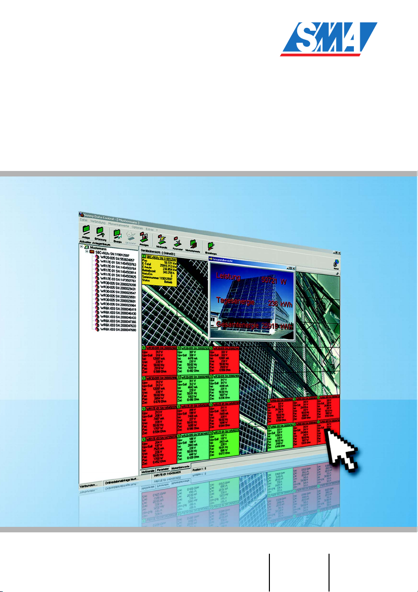
Sunny Data Control
Management Software for Sunny Beam
and Sunny Boy Control
User Manual Version 4.2 SDC-TEN080642
Page 2

Page 3

SMA Technologie AG Table of Contents
Table Of Contents
1 Notes on this Manual. . . . . . . . . . . . . . . . . . . . . . 9
1. 1 Target Group. . . . . . . . . . . . . . . . . . . . . . . . . . . . . 9
1. 2 Validity . . . . . . . . . . . . . . . . . . . . . . . . . . . . . . . . . 9
1. 3 Symbols Used . . . . . . . . . . . . . . . . . . . . . . . . . . . . 9
1. 4 Typographic Conventions . . . . . . . . . . . . . . . . . . . 10
2 Sunny Data Control . . . . . . . . . . . . . . . . . . . . . . 11
2. 1 What is new?. . . . . . . . . . . . . . . . . . . . . . . . . . . . 11
2. 2 Scope of Delivery. . . . . . . . . . . . . . . . . . . . . . . . . 11
2. 3 Scope of Application . . . . . . . . . . . . . . . . . . . . . . 12
2. 4 Functions . . . . . . . . . . . . . . . . . . . . . . . . . . . . . . . 14
2.4. 1 System Requirements . . . . . . . . . . . . . . . . . . . . . . . . . . . . . . .15
2. 5 Identification . . . . . . . . . . . . . . . . . . . . . . . . . . . . 15
2.5. 1 Software Version . . . . . . . . . . . . . . . . . . . . . . . . . . . . . . . . . .15
3 Safety Instructions . . . . . . . . . . . . . . . . . . . . . . . 16
4 Connecting the PC to an Inverter . . . . . . . . . . . . 17
5 Connecting the PC to a Communication Device . 18
5. 1 Notes on the Use of Level Converters . . . . . . . . . . . 20
5. 2 Sunny Boy Control / Plus . . . . . . . . . . . . . . . . . . . 22
5.2. 1 Connection via RS232 . . . . . . . . . . . . . . . . . . . . . . . . . . . . . .22
5.2. 2 Connection via RS485 . . . . . . . . . . . . . . . . . . . . . . . . . . . . . .24
5.2. 3 Connection via the Analog Modem NET Piggy-Back . . . . . . . . .28
5.2. 4 Connection via the ISDN NET Piggy-Back. . . . . . . . . . . . . . . . .29
5.2. 5 Connection via the GSM NET Piggy-Back. . . . . . . . . . . . . . . . .30
5.2. 6 Connection via the Ethernet NET Piggy-Back . . . . . . . . . . . . . . .31
5. 3 Sunny Boy Control Light . . . . . . . . . . . . . . . . . . . . 32
5.3. 1 Connection via RS232 . . . . . . . . . . . . . . . . . . . . . . . . . . . . . .32
5. 4 Sunny Beam . . . . . . . . . . . . . . . . . . . . . . . . . . . . 34
5.4. 1 Connection via USB . . . . . . . . . . . . . . . . . . . . . . . . . . . . . . . .34
User Manual SDC-TEN080642 Page 3
Page 4

Table of Contents SMA Technologie AG
6 Installation of Sunny Data Control . . . . . . . . . . . 35
6. 1 Installing Sunny Data Control. . . . . . . . . . . . . . . . . 35
7 Sunny Data Control User Interface. . . . . . . . . . . 37
7. 1 Navigation Area . . . . . . . . . . . . . . . . . . . . . . . . . 38
7. 2 Plant tree . . . . . . . . . . . . . . . . . . . . . . . . . . . . . . . 39
7. 3 Display Area . . . . . . . . . . . . . . . . . . . . . . . . . . . . 40
8 Initial Settings. . . . . . . . . . . . . . . . . . . . . . . . . . . 41
8. 1 Creating Plants. . . . . . . . . . . . . . . . . . . . . . . . . . . 41
8.1. 1 Brief Overview. . . . . . . . . . . . . . . . . . . . . . . . . . . . . . . . . . . .41
8.1. 2 Changing Plant Names, Creating / Deleting Plants . . . . . . . . . .42
8. 2 Loading a Plant . . . . . . . . . . . . . . . . . . . . . . . . . . 45
8. 3 Setting the Communication Connection . . . . . . . . . . 46
8.3. 1 COM1 – COM255 . . . . . . . . . . . . . . . . . . . . . . . . . . . . . . . .46
8.3. 2 Modem. . . . . . . . . . . . . . . . . . . . . . . . . . . . . . . . . . . . . . . . .48
8.3. 3 Network . . . . . . . . . . . . . . . . . . . . . . . . . . . . . . . . . . . . . . . .48
8.3. 4 Sunny Beam (USB). . . . . . . . . . . . . . . . . . . . . . . . . . . . . . . . .51
8.3. 5 Setting the Transport Protocol . . . . . . . . . . . . . . . . . . . . . . . . .52
8. 4 Detecting Devices. . . . . . . . . . . . . . . . . . . . . . . . . 53
8.4. 1 Narrowing the Scope of Device Detection . . . . . . . . . . . . . . . .54
9 Setting Parameters (Installer). . . . . . . . . . . . . . . 55
10 Displaying Data . . . . . . . . . . . . . . . . . . . . . . . . . 58
10. 1 Creating a Device Overview . . . . . . . . . . . . . . . . . 59
10.1. 1 Displaying or Concealing Devices . . . . . . . . . . . . . . . . . . . . . .61
10.1. 2 Arranging the Fields . . . . . . . . . . . . . . . . . . . . . . . . . . . . . . . .62
10.1. 3 Displaying or Concealing the Graticule . . . . . . . . . . . . . . . . . .63
10.1. 4 Setting the Data Query Sequence . . . . . . . . . . . . . . . . . . . . . .64
10.1. 5 Maximizing the Device Overview (Online Display) . . . . . . . . . .64
10. 2 Selecting Channels for Spot Value Queries . . . . . . . 66
10. 3 Setting the Performance Display. . . . . . . . . . . . . . . 68
10. 4 Setting the Communication Quality. . . . . . . . . . . . . 70
Page 4 SDC-TEN080642 User Manual
Page 5

SMA Technologie AG Table of Contents
10. 5 Changing the Color Behavior of the Device Fields . . 72
10. 6 Accessing Individual Device Information . . . . . . . . . 76
10. 7 Setting the Quick Information. . . . . . . . . . . . . . . . . 78
10. 8 Configuring the Total Overview . . . . . . . . . . . . . . . 80
10. 9 Overview Management . . . . . . . . . . . . . . . . . . . . 84
10.9. 1 Renaming a Device Overview . . . . . . . . . . . . . . . . . . . . . . . . .86
10.9. 2 Copying a Device Overview . . . . . . . . . . . . . . . . . . . . . . . . . .87
10.9. 3 Saving a Device Overview . . . . . . . . . . . . . . . . . . . . . . . . . . .88
10.9. 4 Deleting a Device Overview . . . . . . . . . . . . . . . . . . . . . . . . . .89
10.9. 5 Loading a Device Overview . . . . . . . . . . . . . . . . . . . . . . . . . .90
10. 10 Activating / Deactivating Spot Value Querying . . . . 91
11 Managing Data and Saving Data Locally . . . . . 92
11. 1 Reading Out and Saving Data from Sunny Beam. . . 92
11. 2 Saving Data in Excel Format . . . . . . . . . . . . . . . . . 93
11. 3 Saving Data in CSV Format . . . . . . . . . . . . . . . . . . 94
11.3. 1 Creating a New CSV Type . . . . . . . . . . . . . . . . . . . . . . . . . . .94
11.3. 2 Structure of the Standard CSV Format . . . . . . . . . . . . . . . . . .101
11. 4 Direct Data Acquisition from an Inverter . . . . . . . . 102
11.4. 1 Setting up the Data Filing Structure. . . . . . . . . . . . . . . . . . . . .102
11.4. 2 Saving and Viewing Data . . . . . . . . . . . . . . . . . . . . . . . . . . .106
11.4. 3 Sending Data to Sunny Portal . . . . . . . . . . . . . . . . . . . . . . . .107
11. 5 Setting up Sunny Boy Control Channel Recording . 107
11. 6 Reading Out Data Saved on the Sunny Boy Control 109
11.6. 1 Storage Time Refresh . . . . . . . . . . . . . . . . . . . . . . . . . . . . . .111
11.6. 2 Setting Time Ranges . . . . . . . . . . . . . . . . . . . . . . . . . . . . . . .112
11.6. 3 Resetting Time Ranges . . . . . . . . . . . . . . . . . . . . . . . . . . . . .113
11.6. 4 Channel Recording Icons . . . . . . . . . . . . . . . . . . . . . . . . . . .113
11.6. 5 Structure of the Excel Files. . . . . . . . . . . . . . . . . . . . . . . . . . .114
11. 7 Configuring the Automatic Readout . . . . . . . . . . . 116
11.7. 1 Setting a Task . . . . . . . . . . . . . . . . . . . . . . . . . . . . . . . . . . .116
11.7. 2 Editing/Deleting a Task . . . . . . . . . . . . . . . . . . . . . . . . . . . .119
User Manual SDC-TEN080642 Page 5
Page 6

Table of Contents SMA Technologie AG
11.7. 3 Deactivating the Automatic Readout. . . . . . . . . . . . . . . . . . . .120
11. 8 Creating a Chart in Excel . . . . . . . . . . . . . . . . . . 121
11.8. 1 Automatic Analysis . . . . . . . . . . . . . . . . . . . . . . . . . . . . . . . .122
11.8. 2 Manual Analysis . . . . . . . . . . . . . . . . . . . . . . . . . . . . . . . . .125
12 Transferring Data to the Internet . . . . . . . . . . . 128
12. 1 System Requirements. . . . . . . . . . . . . . . . . . . . . . 128
12. 2 Reading Out the Complete Time Range . . . . . . . . 128
12. 3 Configuring Sunny Portal Mail . . . . . . . . . . . . . . . 129
12. 4 Sending Sunny Portal Mail . . . . . . . . . . . . . . . . . 132
12.4. 1 After Automatic Data Query . . . . . . . . . . . . . . . . . . . . . . . . .132
12.4. 2 After Manual Data Query . . . . . . . . . . . . . . . . . . . . . . . . . . .132
12. 5 Transferring the Device Overview to the Internet . . 133
12.5. 1 Writing the Online Data File . . . . . . . . . . . . . . . . . . . . . . . . .134
12.5. 2 Structure of the Online Data Files. . . . . . . . . . . . . . . . . . . . . .135
12. 6 Internet Server (SDC Agent). . . . . . . . . . . . . . . . . 140
12.6. 1 Overview . . . . . . . . . . . . . . . . . . . . . . . . . . . . . . . . . . . . . .140
12.6. 2 Configuring and Activating the Internet Server. . . . . . . . . . . . .142
12. 7 SDC Agent . . . . . . . . . . . . . . . . . . . . . . . . . . . . 145
12. 8 The Java Applet . . . . . . . . . . . . . . . . . . . . . . . . . 149
12.8. 1 General Applet Parameters . . . . . . . . . . . . . . . . . . . . . . . . . .150
12.8. 2 Component-specific Parameters . . . . . . . . . . . . . . . . . . . . . . .154
12.8. 3 Chart Display . . . . . . . . . . . . . . . . . . . . . . . . . . . . . . . . . . .157
12.8. 4 Device Field Display. . . . . . . . . . . . . . . . . . . . . . . . . . . . . . .161
12.8. 5 Numerical Display . . . . . . . . . . . . . . . . . . . . . . . . . . . . . . . .162
12.8. 6 Overview of Parameters . . . . . . . . . . . . . . . . . . . . . . . . . . . .164
12.8. 7 Example of an HTML Page . . . . . . . . . . . . . . . . . . . . . . . . . .167
Page 6 SDC-TEN080642 User Manual
Page 7

SMA Technologie AG Table of Contents
13 Additional Functions. . . . . . . . . . . . . . . . . . . . . 169
13. 1 Replacing a Device . . . . . . . . . . . . . . . . . . . . . . 169
13.1. 1 Updating the Device Type. . . . . . . . . . . . . . . . . . . . . . . . . . .170
13. 2 Device Information . . . . . . . . . . . . . . . . . . . . . . . 171
13.2. 1 Setting the Device Name and Device ID. . . . . . . . . . . . . . . . .172
13.2. 2 Changing a Device's Network Address . . . . . . . . . . . . . . . . .175
13. 3 Removing Devices . . . . . . . . . . . . . . . . . . . . . . . 176
13. 4 Adding a Device . . . . . . . . . . . . . . . . . . . . . . . . 176
13. 5 Sorting Devices . . . . . . . . . . . . . . . . . . . . . . . . . 177
13. 6 Creating a Color Palette for Device Fields. . . . . . . 177
13. 7 Changing the Fonts of Device Fields . . . . . . . . . . . 178
13. 8 Background Images . . . . . . . . . . . . . . . . . . . . . . 179
13. 9 Packet Monitor. . . . . . . . . . . . . . . . . . . . . . . . . . 182
13. 10 Changing the Security Level (Installer Password) . . 184
13. 11 Locking the Device Overview (Online Display) . . . 185
13. 12 Timeouts . . . . . . . . . . . . . . . . . . . . . . . . . . . . . . 186
13.12. 1 Settings at the Sunny Central Control . . . . . . . . . . . . . . . . . . .186
14 Troubleshooting . . . . . . . . . . . . . . . . . . . . . . . . 187
14. 1 Errors Upon Use of Sunny Data Control . . . . . . . . 187
14. 2 Java Applet Error Messages . . . . . . . . . . . . . . . . 188
14. 3 Directory Structure . . . . . . . . . . . . . . . . . . . . . . . 189
14. 4 Setting the Language . . . . . . . . . . . . . . . . . . . . . 190
15 Overview of Menu Functions . . . . . . . . . . . . . . 191
16 Contact. . . . . . . . . . . . . . . . . . . . . . . . . . . . . . . 193
User Manual SDC-TEN080642 Page 7
Page 8

Table of Contents SMA Technologie AG
Page 8 SDC-TEN080642 User Manual
Page 9
SMA Technologie AG N ot e s on t h is M a nu a l
1 Notes on this Manual
1. 1 Target Group
This manual is for installers as well as end users. It includes a description of the system
and instructions for the commissioning and operation of the device. Some of the
procedures may only be done by trained personnel, these procedures are marked with
a danger symbol.
1. 2 Validity
This documentation for the Sunny Data Control is valid for software version 3.93 and
higher. How to display the software version is described in chapter 2. 5 „Identification”
(page 15).
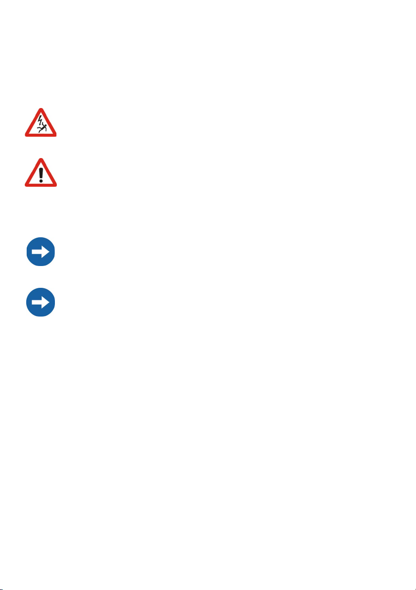
1. 3 Symbols Used
To ensure optimum use of this document, note the following explanation of the symbols
used.
This symbol indicates a notice which, if ignored, will make the procedure or operation more difficult.
This symbol indicates an example, which serves to help explain a working step.
This symbol identifies a warning, which indicates a fact or feature which,
if ignored, can cause serious damage to the device.
This symbol indicates a statement which, if ignored, could lead to serious
injury or death.
User Manual SDC-TEN080642 Page 9
Page 10
Notes on this Manual SMA Technologie AG
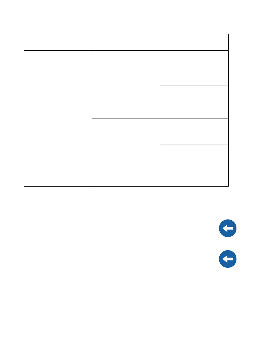
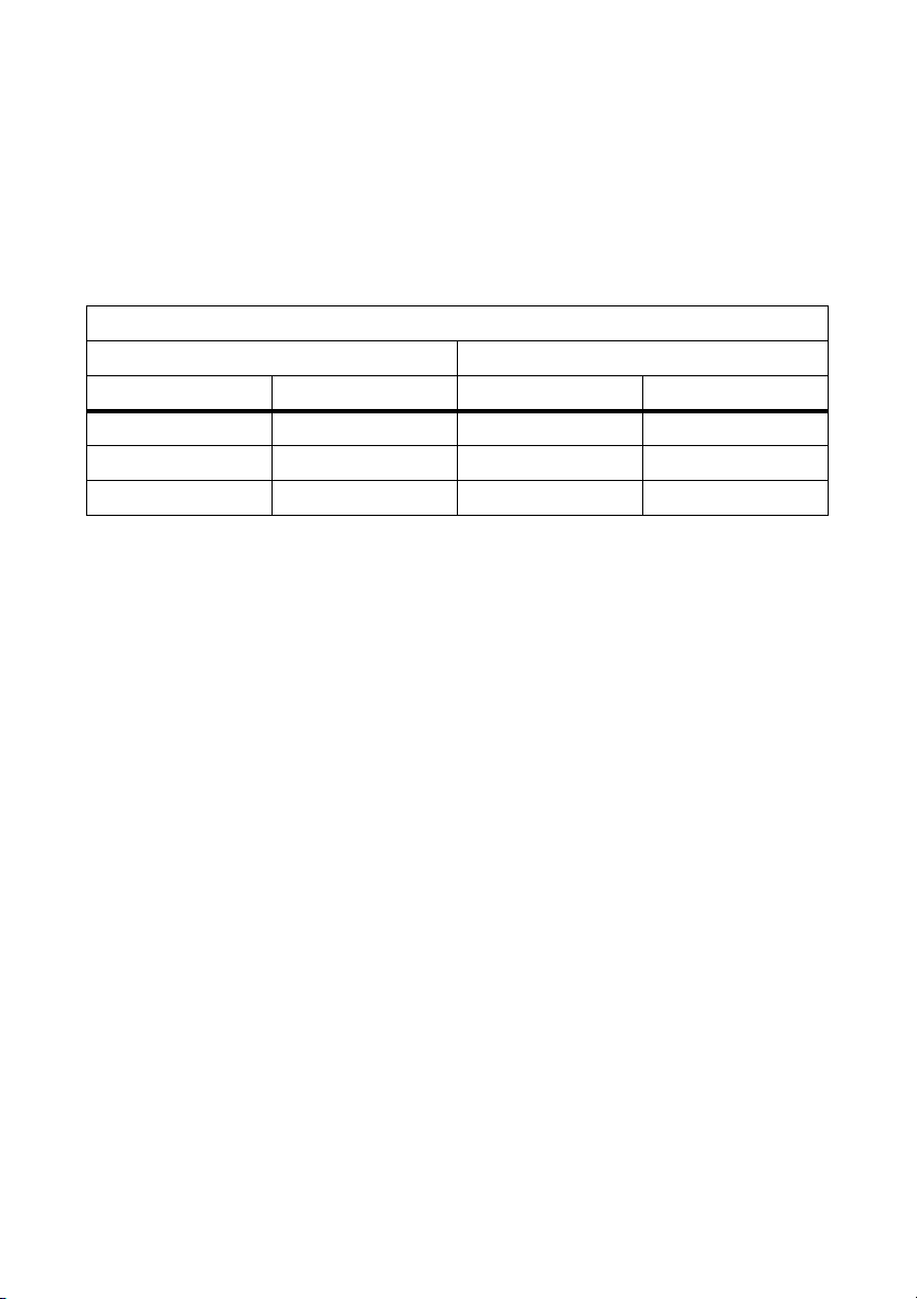
1. 4 Typographic Conventions
This user manual uses the typographic conventions indicated in the following table.
Example of the convention Description
<Ok> < > This symbol indicates a button
"Options" Menu items and commands are shown in
quotation marks (in conjunction with "Click
on..." or "Select..." ).
"Options / Settings" If several menu items must be selected,
these are shown separated by a slash (in
conjunction with "Click on..." or
"Select..." ).
Page 10 SDC-TEN080642 User Manual
Page 11

SMA Technologie AG Sunny Data Control
2 Sunny Data Control
2. 1 What is new?
• The data transfer to Sunny Portal is now also possible when the inverter is directly
connected to the PC.
- See chapter 12. 3 „Configuring Sunny Portal Mail” (page 129).
2. 2 Scope of Delivery
The program "Sunny Data Control" can be downloaded from www.SMA.de in the
download area, or ordered as a CD: (SMA order number SMA-CDROM).
User Manual SDC-TEN080642 Page 11
Page 12
Sunny Data Control SMA Technologie AG
2. 3 Scope of Application
Sunny Data Control is a PC program from SMA Technologie AG with which you can
realize long-term storage of the data from your photovoltaic plant, and also visualize
it. Sunny Data Control queries the data from your communication device (Sunny Boy
Control and Sunny Beam) and saves it as Microsoft Excel files or CSV files on your PC.
With Sunny Data Control, for example, you can set up a complete overview of all
inverter data (e.g.Pac, E-total, E-today) and display the inverter data in Excel in the form
of charts. As an installer you can set the inverters' parameters, and you can send the
data to Sunny Portal for visualization and storage. See www.SunnyPortal.com for more
information on Sunny Portal.
With Sunny Data Control software version 3.81 and above, you can also connect an
inverter directly to the PC. This connection is only permissible for the purpose of
servicing, and may not be operated on a long-term basis.
Page 12 SDC-TEN080642 User Manual
Page 13
SMA Technologie AG Sunny Data Control
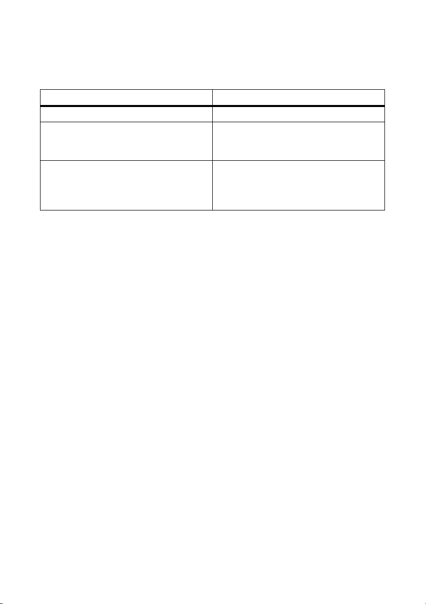
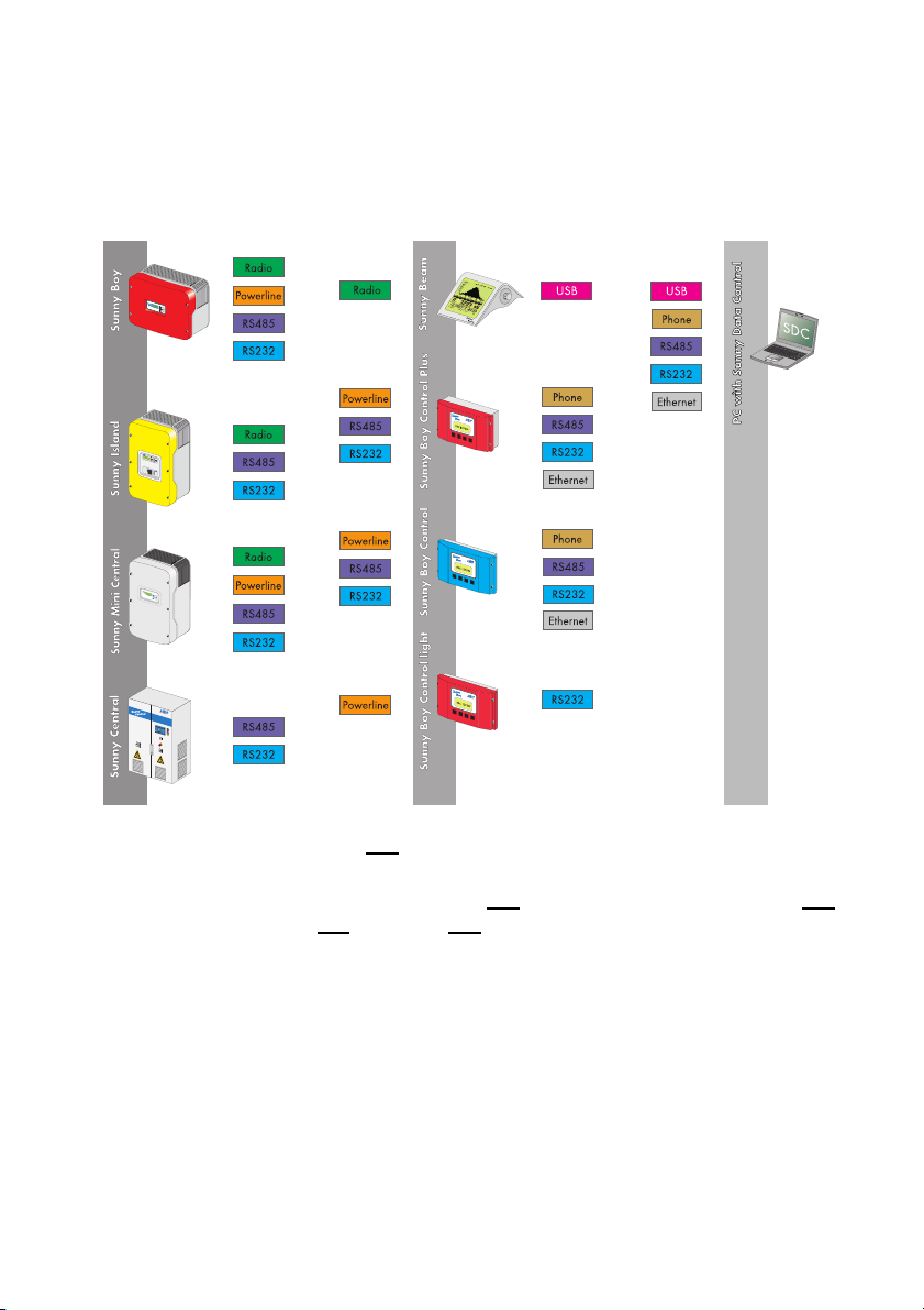
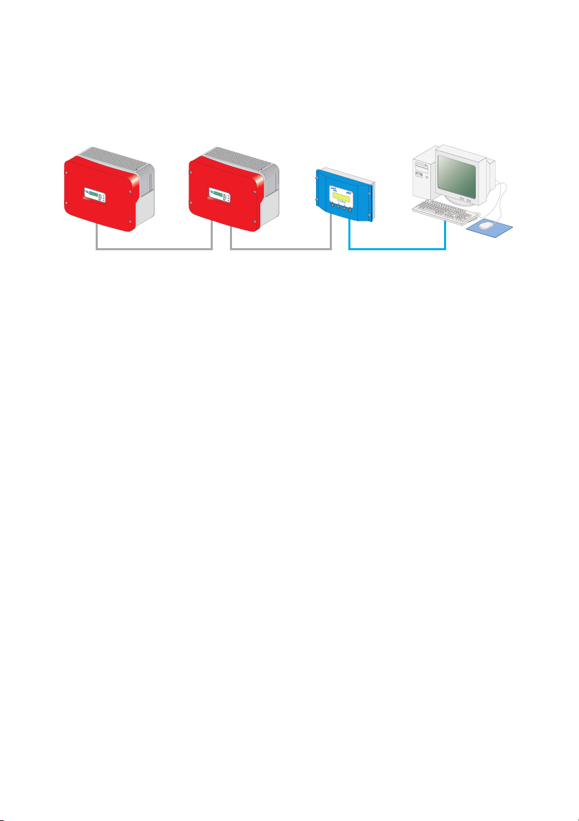
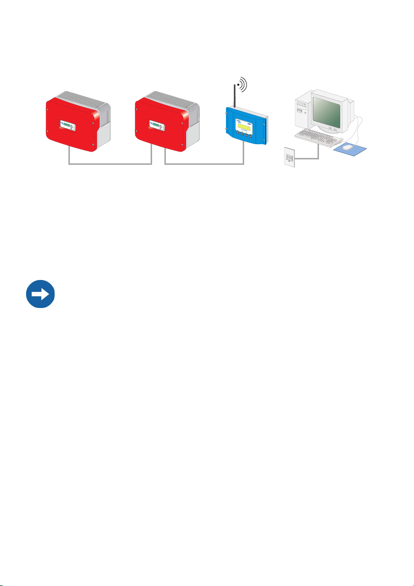
PC Connection Possibilities
The following figure provides an overview of the connection possibilities from inverter
to PC with Sunny Data Control. You can obtain further information at www.SMA.de,
and in section 4 „Connecting the PC to an Inverter” (page 17).
It is only ever possible to have one type of connection between inverters, and to the
communication device.
With an RS232 and USB connection, only one inverter can be connected to one
communication device, or one inverter to one PC.
User Manual SDC-TEN080642 Page 13
Page 14

Sunny Data Control SMA Technologie AG
2. 4 Functions
Supported Communication devices:
• Sunny Boy Control/Plus/Light (starting with software version 2.0)
• Sunny Central Control (starting with software version 2.0)
•Sunny Beam
Supported inverters for direct connection to the PC (Sunny Data Control software
version 3.81 and above):
•Sunny Boys
• Sunny Mini Centrals
• Windy Boy
Possibility to connect one
inverter directly to the PC:
• via USB service cable
Functions
• Continuous system monitoring and acquisition of measurement data by means of
accessing your Sunny Boy Control
• Direct gathering of measurement data from an inverter through its direct
connection to the PC
• Remote monitoring via modem
• Export of data for presentation of operating data on the Internet (e.g. via Sunny
Portal)
• Graphic PC display of all measurement data and operating modes
• "Online display" with color-coded indication of the present output of each Sunny
Boy in your plant
• Configuration of Sunny Boys and adjustment of Sunny Boys' parameters
Page 14 SDC-TEN080642 User Manual
Page 15
SMA Technologie AG Sunny Data Control
2.4. 1 System Requirements
• Operating system: Windows 98 or above
• Available hard disk space: at least 20 MB
• RS232 interface: COM1 to COM255 (D-Sub9/25) or Ethernet
• RS232
- on the PC: COM1 to COM255
- on the Sunny Boy Control: RS232 Piggy-Back
- Data cable: up to 15 m
• RS485
- on the PC: Interface converter
- on the Sunny Boy Control: RS485 Piggy-Back
- Data cable: up to 1200 m
•Ethernet
- on the PC: Ethernet card
- on the Sunny Boy Control: NET socket, NET Piggy-Back
- Ethernet: up to 100 m
•USB
- on the Sunny Beam: up to 3 m
2. 5 Identification
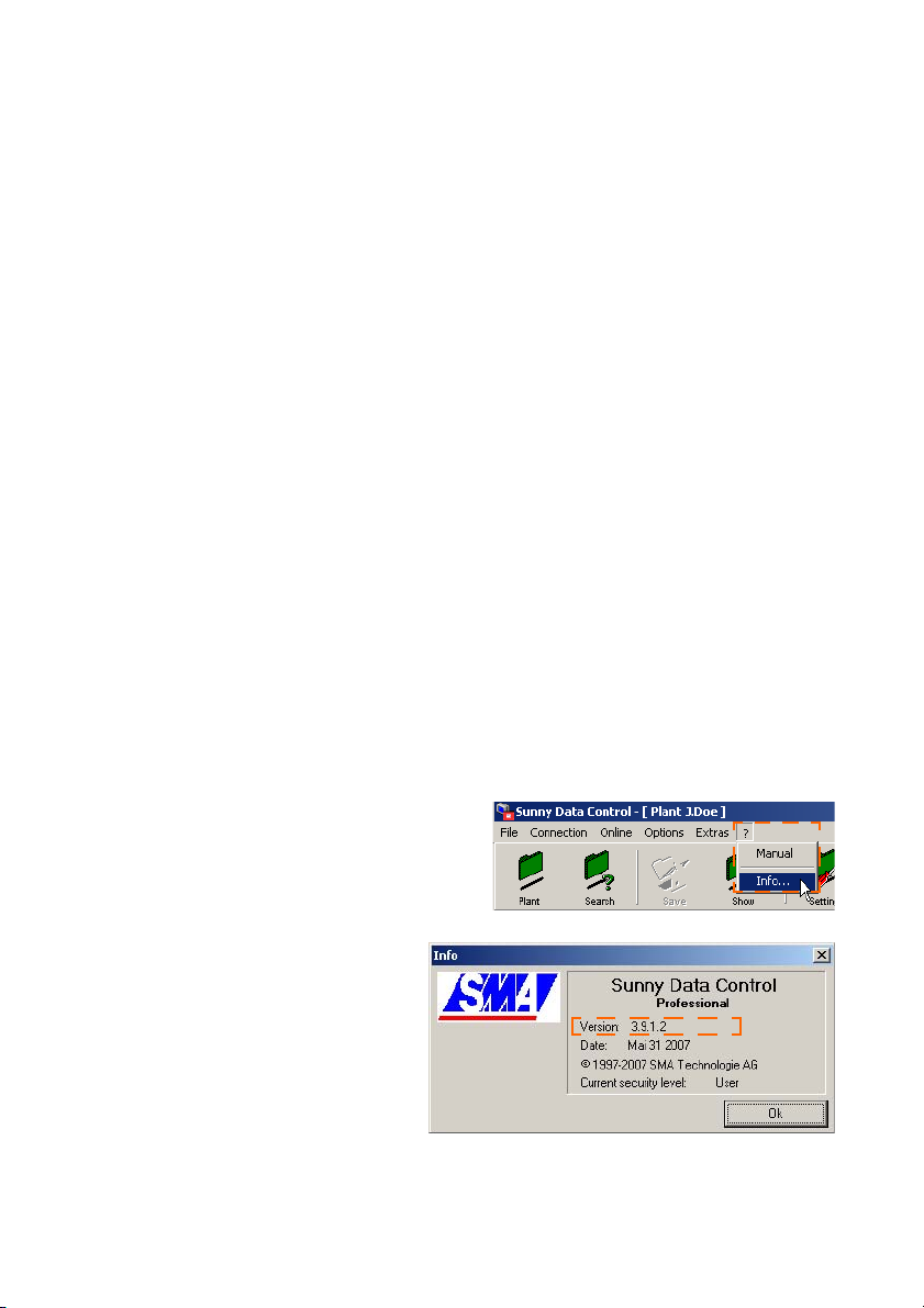
2.5. 1 Software Version
In Sunny Data Control, you can display the
Sunny Data Control software version via the
menu item "?/Info..." .
This shows the following information:
1. Software version and date
2. Current security level of the user,
see section 13. 10 „Changing
the Security Level (Installer Password)” (page 184).
User Manual SDC-TEN080642 Page 15
Page 16
Safety Instructions SMA Technologie AG
3 Safety Instructions
Please follow all operating and safety instructions in this manual. Failure to follow these
instructions could result in damage to the device and cause personal injury.
All work on the inverters may only be performed by qualified electricians!
Follow all safety instructions contained in the inverter documentation!
With the Sunny Data Control program, your PV plant's safety-related
inverter parameters can be changed. Such parameters may only be
changed after consulting your energy supply company.
Operating Instructions
Data collected by Sunny Data Control regarding the power generated by your
solar power plant can deviate from the electric meter. The Sunny Data Control
data may not be used for billing purposes.
The PC, and thus Sunny Data Control, can be connected to the Internet via an additional router. Adequate security measures must be taken by using upstream
hardware and software (firewall).
Page 16 SDC-TEN080642 User Manual
Page 17

SMA Technologie AG Connecting the PC to an Inverter
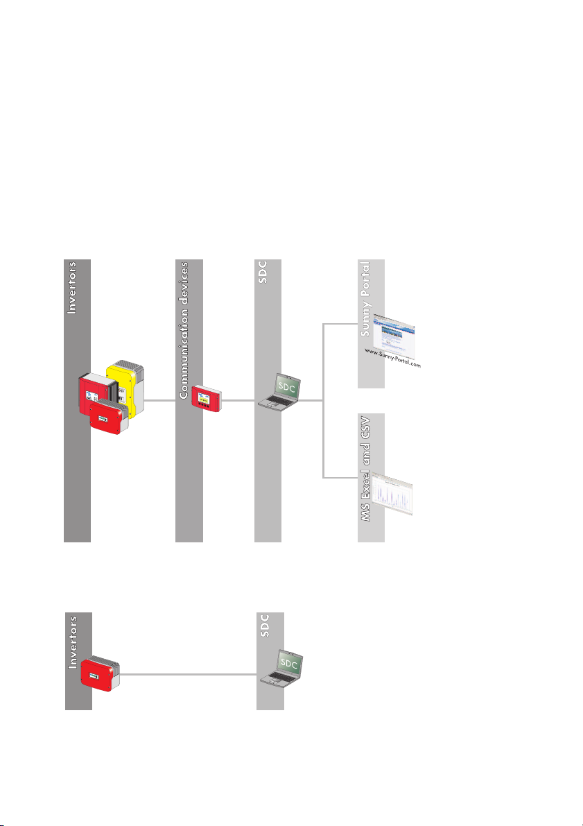
4 Connecting the PC to an Inverter
A direct connection of a PC to the inverter is only intended for the purpose
of servicing, and may not be operated on a long-term basis.
The direct connection is made via the SMA USB service interface with a 1.5 m cable
and a USB interface for the PC connection (SMA order number: USBPBS)
For further information regarding this connection, please refer to the USB service
interface's user manual.
Sunny Data Control supports the direct connection of an inverter to the PC with
Sunny Data Control software version 3.81 and above.
Data Acquisition
How to gather and save data from an inverter connected directly to a PC is described
in Chapter 11. 4 „Direct Data Acquisition from an Inverter” (page 102).
User Manual SDC-TEN080642 Page 17
Page 18
Connecting the PC to a Communication Device SMA Technologie AG
5 Connecting the PC to a Communication Device
To connect several inverters to the PC, there are various communication devices at your
disposal.
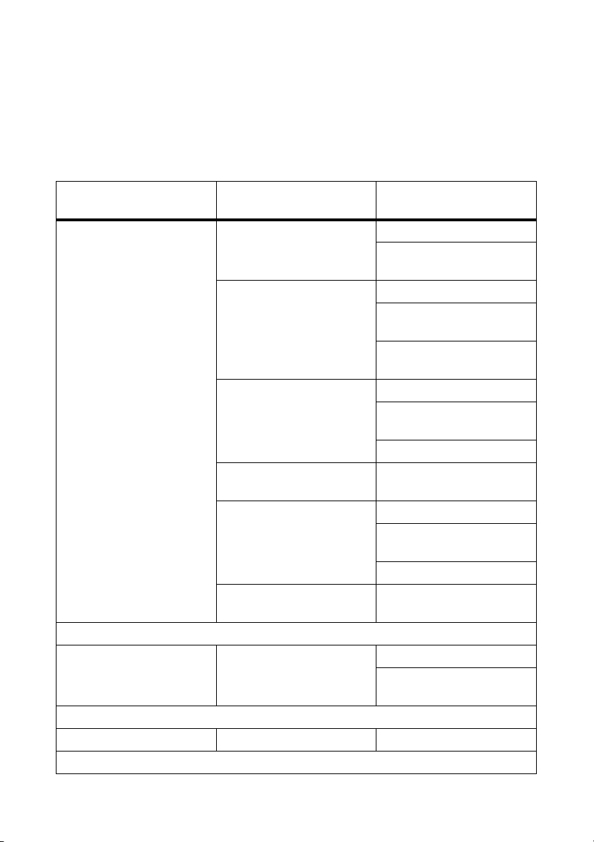
The following table shows the communication devices and the possible connection
types.
Communication device Communication device's
interface
Sunny Boy Control / Plus RS232 Piggy-Back RS232 connection
RS485 Piggy-Back RS485 connection
NET Piggy-Back with
analog modem
NET Piggy-Back with ISDN
modem
NET Piggy-Back with GSM
modem
NET Piggy-Back with
Ethernet
PC's interface
RS232 to USB level
converter
RS485 to USB level
converter
RS485 to RS232 level
converter
analog modem
ISDN modem (with CAPI
driver)
GSM modem
ISDN modem
analog modem
ISDN modem (with CAPI
driver)
GSM modem
Ethernet network card
Sunny Boy Control Light RS232 Piggy-Back RS232 connection
RS232 to USB level
converter
Sunny Beam USB USB connection
Page 18 SDC-TEN080642 User Manual
Page 19
SMA Technologie AG Connecting the PC to a Communication Device
Communication device Communication device's
PC's interface
interface
Sunny Central Control RS232 Piggy-Back RS232 connection
RS232 to USB level
converter
RS485 Piggy-Back RS485 connection
RS485 to USB level
converter
RS485 to RS232 level
converter
NET Piggy-Back with
analog modem
analog modem
ISDN modem (with CAPI
driver)
GSM modem
NET Piggy-Back with ISDN
ISDN modem
modem
NET Piggy-Back with
Ethernet network card
Ethernet
The following sections describe the various options for connection of the communication
devices, provide recommendations for cabling, and include wiring diagrams.
Information on the Sunny Central Control
For a Sunny Central Control, certain settings in Sunny Data Control versions 3.5
and beyond must be adopted to exceed time limits. See Chapter 13.12. 1 „Settings at the Sunny Central Control” (page 186)
The Sunny Central Control is a variant of the Sunny Boy Control, which is directly
built into the Sunny Central. Throughout this manual, only the Sunny Boy Control
is mentioned. All sections which apply to the Sunny Boy Control also apply to the
Sunny Central Control.
User Manual SDC-TEN080642 Page 19
Page 20

Connecting the PC to a Communication Device SMA Technologie AG
5. 1 Notes on the Use of Level Converters
Level inverters are devices which convert data from one signal type to another, for
instance from RS485 to USB. With the aid of these level converters, a Sunny Boy
Control / Plus or Sunny Boy Control Light can be connected to a PC which does not
have the appropriate interface.
Compatibility with all level converters available on the market cannot be guaranteed.
SMA provides the following level converters. These level converters have been tested,
and function with the Sunny Boy Control / Plus and the Sunny Boy Control Light:
• RS232/RS485 to USB
- SMA order number: I-7561
• RS485 to RS232
- SMA order number: I-7520
Page 20 SDC-TEN080642 User Manual
Page 21

SMA Technologie AG Connecting the PC to a Communication Device
User Manual SDC-TEN080642 Page 21
Page 22
Connecting the PC to a Communication Device SMA Technologie AG
5. 2 Sunny Boy Control / Plus
5.2. 1 Connection via RS232
RS232
RS232 communication characteristics:
• A maximum of one Sunny Boy Control / Plus can be connected to a PC.
• The PC must be equipped with an RS232 port. If it is not, please read section 5.
1 „Notes on the Use of Level Converters” (page 20).
• The Sunny Boy Control / Plus requires an RS232 Piggy-Back at the PC (COM 2)
port.
Alternatively, the AUX (COM 3) port on the Sunny Boy Control Plus can be used
if the port is equipped with an RS232 Piggy-Back.
• The maximum total cable length is 12 m
Cabling Recommendations
The connection between the Sunny Boy Control and the PC occurs by means of a
commercially available null modem cable. Use the null modem cable provided.
If the length proves insufficient, use a commercially available null modem cable of the
required length.
Jumper Functions at the Sunny Boy Control / Plus
With RS232 communication, no jumper must be mounted on the Sunny Boy Control /
Plus at the PC (COM 2) port, or on the Sunny Boy Control Plus at the AUX (COM 3)
port.
Page 22 SDC-TEN080642 User Manual
Page 23
SMA Technologie AG Connecting the PC to a Communication Device
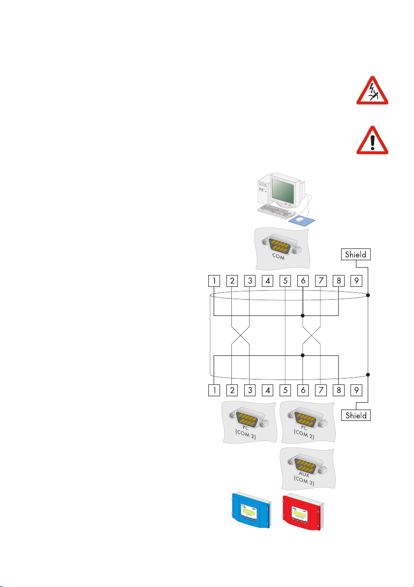
Wiring Diagram
Observe all safety instructions in the Sunny Boy Control / Plus
documentation, and in the PC documentation.
Shut down the PC before you connect the Sunny Boy Control / Plus, as
otherwise one or both COM ports may be damaged.
1. Use the provided null modem cable, or a commercially available
null modem cable of the required
length.
2. Plug the 9-pin D-Sub female connector into a free COM port on
your PC.
3. Lay the cable properly so that
there is no risk of persons tripping
over it.
4. Plug the 9-pin D-Sub female connector into the port on the Sunny
Boy Control which is equipped
with the RS232 interface.
Sunny Boy Control: PC (COM 2)
Sunny Boy Control Plus: (COM 2)
or AUX (COM 3)
5. Make sure that jumpers A, B and
C are not plugged in the port
used.
Sunny Boy Control
User Manual SDC-TEN080642 Page 23
Sunny Boy Control Plus
Page 24
Connecting the PC to a Communication Device SMA Technologie AG
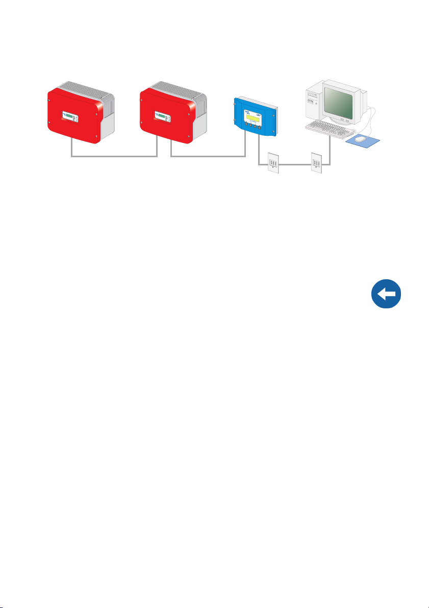
5.2. 2 Connection via RS485
RS485
RS485 communication characteristics:
• Up to 50 Sunny Boy Control / Plus devices can be connected to a PC.
• The PC must be equipped with an RS485 port. If it is not, please read section 5.
1 „Notes on the Use of Level Converters” (page 20).
• Each Sunny Boy Control requires an RS485 Piggy-Back at the PC (COM 2) port.
Alternatively, at the Sunny Boy Control Plus, the AUX (COM 3) port can be used,
if this is equipped with an RS232 Piggy-Back.
• The maximum total cable length is 1200 m
Cabling Recommendations
The cable length and quality have an effect on the signal quality. To achieve a good
quality signal, observe the following instructions regarding cabling:
• Use metallic D-Sub female connectors. Connectors made of plastic, or metallized
plastic, can cause faulty data transfer.
• For the outdoors, use a communications cable with the following important
qualities:
- Cross-section: at least 2 x 2 x 0,22 mm
-shielded
-Twisted Pair
- UV-resistant
We recommend the following cable types for outdoors:
SMA communications cable: COMCAB-OUTxxx*
*available in the following lengths xxx = 100 m/200 m/500 m und 1000 m.
Lappkabel: UNITRONIC Li2YCYv 2 x 2 x 0,22 mm
2
, and at least 2 x 2 x AWG 24
2
For the outdoors you can also use a data cable designed for indoor use, if you
protect it against UV radiation with an appropriate cable duct.
Page 24 SDC-TEN080642 User Manual
Page 25
SMA Technologie AG Connecting the PC to a Communication Device
• We recommend the following cable types for indoors:
SMA data cable: COMCAB-INxxx*
*available in the following lengths xxx = 100 m/200 m/500 m und 1000 m.
Lappkabel: UNITRONIC Li2YCY (TP) 2 x 2 x 0,22 mm
Helukabel: PAAR-TRONIC-Li-2YCY 2 x 2 x 0,22 mm
2
2
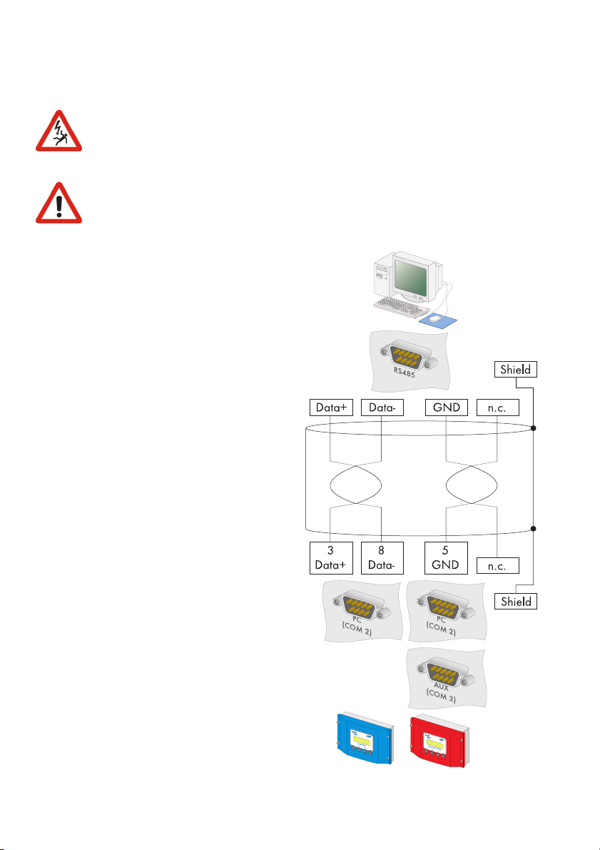
Pin Assignment of the Connection Cable
Sunny Boy Control PC
Signal Pin Pin Signal
Data + 3 Data +
Data- 8 Data-
GND 5 GND
Jumper Functions
Termination
To increase the signal quality of the RS485 data bus, it must be terminated at both ends.
Each termination occurs with a 120 W resistor between the two data lines. Terminate
the last Sunny Boy Control / Plus by means of a jumper. The position of the jumper is
described in the user manual of the Sunny Boy Control / Plus.
Signal Biasing
To increase the signal quality of the RS485 data bus, a maximum of one bias can be
connected in the data bus. We recommend connecting the bias at the PC.
User Manual SDC-TEN080642 Page 25
Page 26
Connecting the PC to a Communication Device SMA Technologie AG
Wiring Diagram
Observe all safety instructions in the Sunny Boy Control / Plus
documentation, and in the PC documentation.
Shut down the PC before you connect the Sunny Boy Control / Plus, as
otherwise one or both COM ports may become damaged.
1. Plug the 9-pin D-Sub female connector into a free COM port on
your PC. For the pin assignment of
the RS485 connection, please refer to the PC's documentation, or
the plug-in card's documentation.
When connecting the cable, make
sure that Data+ and Data- are a
twisted pair. Shorten the wire of the
fourth, unused conductor, so that
short circuits cannot arise. Take
note of the conductors' color coding:
Data + ____________________
Data- ____________________
GND ____________________
2. If the PC is situated at one of the
two ends of the RS485 data bus,
terminate the end of the cable as
described in the PC's documentation, or in the plug-in card's documentation.
3. Configure the RS485 data bus'
bias as described in the PC's documentation, or the plug-in card's
documentation.
4. Lay the cable properly so that there
is no risk of persons tripping over it.
Sunny Boy Control Sunny Boy Control Plus
Page 26 SDC-TEN080642 User Manual
Page 27
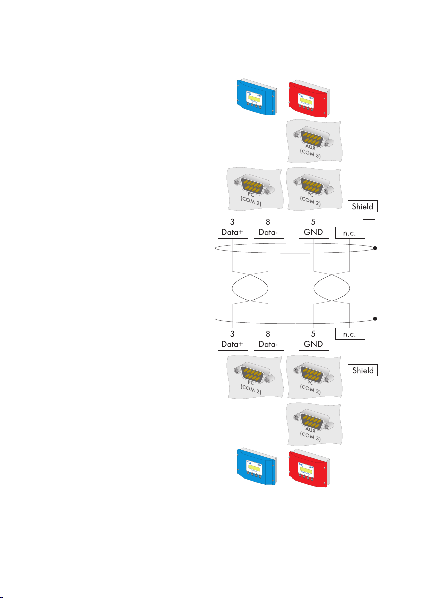
SMA Technologie AG Connecting the PC to a Communication Device
5. Plug the 9-pin D-Sub female connector into the port on the Sunny
Boy Control which is equipped
with the RS485 interface.
Sunny Boy Control: PC (COM 2)
Sunny Boy Control Plus: (COM 2)
or AUX (COM 3)
6. Connect the PC's Data+ with the
Data+ of the Sunny Boy Control /
Plus, and so on. The 3 connections
should be made directly.
7. At the last Sunny Boy Control /
Plus, jumper A must be mounted at
the port used. Jumper A must not
be mounted on any of the other
Sunny Boy Control / Plus devices.
Make sure that jumpers B and C
are not mounted at the port used.
8. Connect the Data+ of the next Sunny Boy Control / Plus with the Data+ of the Sunny Boy Control / Plus
which precedes it, and so on. The
3 connections are directly interconnected.
9. At the last Sunny Boy Control /
Plus, jumper A must be mounted at
the port used. Jumper A must not
be mounted on any of the other
Sunny Boy Control / Plus devices.
Make sure that jumpers B and C
are not mounted at the port used.
Sunny Boy Control Sunny Boy Control Plus
Sunny Boy Control Sunny Boy Control Plus
User Manual SDC-TEN080642 Page 27
Page 28

Connecting the PC to a Communication Device SMA Technologie AG
5.2. 3 Connection via the Analog Modem NET Piggy-Back
Analog Modem Communication Characteristics
• As the connection to the Sunny Boy Control / Plus is established via the telephone
network, it is only ever possible to connect one Sunny Boy Control / Plus with the
PC.
• The PC must be equipped with a modem (analog, ISDN with CAPI driver or
GSM).
• The Sunny Boy Control / Plus requires an "analog modem" version of the NET
Piggy-Back.
Compatibility with all PC modems available on the market cannot be guaranteed.
Connection
1. Connect the PC to the telephone network as described in the modem's user manual.
2. Connect the Sunny Boy Control / Plus to the telephone network as described in
the NET Piggy-Back's user manual.
3. Use the software provided with the PC operating system to establish the connection
between the two devices.
Page 28 SDC-TEN080642 User Manual
Page 29
SMA Technologie AG Connecting the PC to a Communication Device
5.2. 4 Connection via the ISDN NET Piggy-Back
ISDN Modem Communication Characteristics
• As the connection to the Sunny Boy Control / Plus is established via the telephone
network, it is only ever possible to connect one Sunny Boy Control / Plus with the
PC.
• The PC must be equipped with an ISDN modem.
• The Sunny Boy Control / Plus requires an "ISDN" version of the NET Piggy-Back.
Compatibility with all PC modems available on the market cannot be guaranteed.
Connection
1. Connect the PC to the telephone network as described in the modem's user manual.
2. Connect the Sunny Boy Control / Plus to the telephone network as described in
the NET Piggy-Back's user manual.
3. Use the software provided with the PC operating system to establish the connection
between the two devices.
User Manual SDC-TEN080642 Page 29
Page 30
Connecting the PC to a Communication Device SMA Technologie AG
5.2. 5 Connection via the GSM NET Piggy-Back
GSM Modem Communication Characteristics
• As the connection to the Sunny Boy Control / Plus is established via the telephone
network, it is only ever possible to connect one Sunny Boy Control / Plus with the
PC.
• The PC must be equipped with a modem (analog, ISDN with CAPI driver or
GSM).
• The Sunny Boy Control / Plus requires a "GSM" version of the NET Piggy-Back.
Compatibility with all PC modems available on the market cannot be guaranteed.
Connection
1. Connect the PC to the telephone network as described in the modem's user manual.
2. Connect the Sunny Boy Control / Plus to the telephone network as described in
the NET Piggy-Back's user manual.
3. Use the software provided with the PC operating system to establish the connection
between the two devices.
Page 30 SDC-TEN080642 User Manual
Page 31

SMA Technologie AG Connecting the PC to a Communication Device
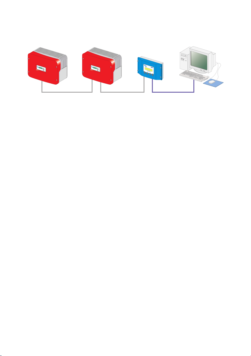
5.2. 6 Connection via the Ethernet NET Piggy-Back
Router or hub
Ethernet Network Communication Characteristics
• Any number of Sunny Boy Control / Plus devices can be connected to a PC via
the Ethernet network. The only limitation is the capability of the PC, whereby the
main memory is the limiting factor.
• A Sunny Boy Control / Plus can be connected directly to a PC.
• The PC must be equipped with an Ethernet network card.
• Each Sunny Boy Control / Plus requires an "Ethernet" version of the NET PiggyBack.
Cabling Recommendations
The cable length and quality can adversely affect the signal quality. To achieve good
results, observe the following instructions.
• For the connection to a hub or router, you require a patch cable.
For the direct connection to a PC, you require a crossover cable.
• Use high quality cable, at least category 5 (STP Cat 5) or higher shielded twisted
pair cable.
• The maximum permitted cable length for Ethernet cable is 100 m.
User Manual SDC-TEN080642 Page 31
Page 32

Connecting the PC to a Communication Device SMA Technologie AG
Connection to an Ethernet Network
1. Connect the PC to the network as described in the Ethernet network card's user
manual.
2. Connect the Sunny Boy Control / Plus to the Ethernet network as described in the
NET Piggy-Back's user manual.
Direct Connection to a Single PC
1. Plug one end of the crossover cable into your PC's Ethernet network card.
2. Plug the other end of the Ethernet network cable into the NET socket of the Sunny
Boy Control / Plus.
3. Lay the cable properly so that there is no risk of persons tripping over it.
5. 3 Sunny Boy Control Light
5.3. 1 Connection via RS232
RS232
RS232 communication characteristics:
• A maximum of one Sunny Boy Control Light can be connected to a PC.
• The PC must be equipped with an RS232 port. If it is not, please read section 5.
1 „Notes on the Use of Level Converters” (page 20).
• The maximum total cable length is 12 m
Cabling Recommendations
The connection between the Sunny Boy Control Light and the PC occurs by means of a
commercially available null modem cable. Use the null modem cable provided.
If the length proves insufficient, use a commercially available null modem cable of the
required length.
Page 32 SDC-TEN080642 User Manual
Page 33

SMA Technologie AG Connecting the PC to a Communication Device
Wiring Diagram
Observe all safety instructions in the Sunny Boy Control / Plus
documentation, and in the PC documentation.
Shut down the PC before you connect the Sunny Boy Control / Plus, as
otherwise one or both COM ports may become damaged.
1. Use the provided null modem cable, or a commercially available null modem cable of the required length.
2. Plug the 9-pin D-Sub female connector into a
free COM port on your PC.
3. Lay the cable properly so that there is no risk of
persons tripping over it.
4. Plug the 9-pin D-Sub female connector into the
PC (COM2) port on the Sunny Boy Control
Light.
Sunny Boy Control Light
User Manual SDC-TEN080642 Page 33
Page 34

Connecting the PC to a Communication Device SMA Technologie AG
5. 4 Sunny Beam
5.4. 1 Connection via USB
USB
USB Communication Characteristics
• A maximum of one Sunny Beam can be connected to a PC.
• The PC must be equipped with a USB port.
• The maximum total cable length is 3 m
Connection
1. Connect the Sunny Beam to the PC as described in the Sunny Beam's user manual.
Page 34 SDC-TEN080642 User Manual
Page 35

SMA Technologie AG Installation of Sunny Data Control
6 Installation of Sunny Data Control
Sunny Data Control can be downloaded from the SMA web server or ordered as a CD.
Installation with Windows Vista:
With Windows Vista, Sunny Data Control must be saved using a path other than
C:\Programs, for example, C:\SMA.
6. 1 Installing Sunny Data Control
1. Before installation, close all Windows programs on your PC.
2. Start the Sunny Data Control installation program (setup file) on
your PC. The Sunny Data Control
installation window opens (see
figure to the right).
3. Follow the program's on-screen
instructions.
SDC agent
4. If you also wish to use
Sunny Data Control
for online presentation of your PV plant,
add a check mark
next to "SDC Agent"
(not necessary for
Sunny Portal).
User Manual SDC-TEN080642 Page 35
Page 36

Installation of Sunny Data Control SMA Technologie AG
Program Shortcut
5. If a program shortcut
(see figure below) for
Sunny Data Control is
to be created on your
PC, leave the check
mark in place (see figure to the right).
6. Once the installation
is finished, you can
launch Sunny Data Control.
7. When you launch Sunny Data Control for the first time, no device is as yet configured to be detected by Sunny Data Control.
8. If you have not yet connected a device, connect it as described in section 5 „Connecting the PC to a Communication Device” (page 18).
9. Subsequently, create a plant and establish the communication connection as described in section 8 „Initial Settings” (page 41).
Page 36 SDC-TEN080642 User Manual
Page 37

SMA Technologie AG Sunny Data Control User Interface
7 Sunny Data Control User Interface
The Sunny Data Control user interface comprises three areas:
• Navigation areaIn the navigation area, you can access and use various Sunny
Data Control functions.
• Plant treeIn the plant tree, the currently selected plant is displayed, along with its
devices which you have detected with Sunny Data Control.
• Display areaIn the display area, three different views can be called up via the
three tabs (see figure below).
- Spotvalues (here, the page "Device Overview" is displayed)
- Channel recording (here, the page "Archive Channels" is displayed)
- Parameters (here, the page "Parameters" is displayed)
Navigation
Area
Plant tree
Tabs
Display Area
(with three tabs)
User Manual SDC-TEN080642 Page 37
Page 38

Sunny Data Control User Interface SMA Technologie AG
7. 1 Navigation Area
The navigation area comprises the menu bar and the menu buttons. The menu buttons
correspond to the most frequently required menu items, and are thus made available to
you as convenient menu buttons for quick access. You can also call up these menu items
via the menu bar.
Menu bar
Menu buttons
The menu bar comprises six main menus:
1. File
2. Connection
3. Spot values
4. Options
5. Extras
6. ?
The menu buttons correspond to the most frequently required menu items:
• PlantAlso accessible in the navigation area via "Options / Choose Plant".
• SearchAlso accessible in the navigation area via "Options / Device Detection".
• SaveThis button can only be selected if the archive channels are currently
displayed in the display area. You can call up the archive channels in the display
area via the "Channel recording" tab.
•Show
• SettingsAlso accessible in the navigation area via "Options / Settings".
Page 38 SDC-TEN080642 User Manual
Page 39

SMA Technologie AG Sunny Data Control User Interface
7. 2 Plant tree
In the plant tree, the currently selected plant
is displayed, along with its devices, which
you have detected with Sunny Data Control.
Here, via the plant tree menu, you can,
forexample, call up the device information of
the selected device, remove the selected
device, add devices, sort devices, or replace
devices.
Some of the actions which you can select in
the plant tree menu apply to the currently
selected device, while other actions apply to
all devices.
You can call up the plant tree menu for the
respective device by clicking on the name of the device with the right mouse
button, or by clicking on the icon pictured here to the right (see also figure
above):
If you call up the plant tree menu via the icon, you must first highlight the respective
device by clicking on the device's name.
Expanding and Collapsing the Plant Tree
You can expand and collapse the plant tree by clicking on the nodes (+/- symbols).
This function is a practical way to maintain an overview if you have a plant with many
devices.
Plant tree
Collapsed plant tree
Expanded plant tree
User Manual SDC-TEN080642 Page 39
Page 40

Sunny Data Control User Interface SMA Technologie AG
7. 3 Display Area
In the display area, three different pages can be called up via the three tabs (see figure
below):
- Spotvalues (here, the page "Device Overview" is displayed)
- Channel recording (here, the page "Archive Channels" is displayed)
- Parameters (here, the page "Parameters" is displayed)
You can call up the Device Overview menu ("Spotvalues" tab) via the following
icon:
(see also figure below), or by clicking on the field of the respective device with the right
mouse button. Some of the actions which you can select in the display area menu apply
to the currently selected device, while other actions apply to all devices.
Name of the current page (here: device overview).
Lock
online display
(device overview)
Three tabs
(here: "Spotvalues" tab active)
Device overview menu
("Spotvalues" tab)
Page 40 SDC-TEN080642 User Manual
Page 41

SMA Technologie AG Initial Settings
8 Initial Settings
8. 1 Creating Plants
With Sunny Data Control, you can create, manage and monitor one or more plants
(e.g. as an installer). However, it is only ever possible to display and edit one
a time (current plant) in the Sunny Data Control window. If you manage several plants,
you must first load the respective plant (see section 8. 2 „Loading a Plant” (page 45)).
Detected devices and settings, such as the communication connection or parameters,
always refer to the respective plant, and are saved as settings for the respective plant.
8.1. 1 Brief Overview
You can call up the window for creating and selecting plants via the menu
item "Options / Choose Plant", or via the "Plant" icon (see figure below). By
default, a plant with the name "My Plant" is always created automatically
during installation.
Current plant
Currently selected plant
All plants already
created
plant at
Load selected plant
Save current plant
Create copy of the selected plant
Create new plant
Rename selected plant
Delete selected plant
User Manual SDC-TEN080642 Page 41
Page 42

Initial Settings SMA Technologie AG
8.1. 2 Changing Plant Names, Creating / Deleting Plants
Changing the Plant Name
By default, a plant with the name "My Plant" is always created automatically by Sunny
Data Control during installation. You can change the plant name which is displayed in
Sunny Data Control, create additional plants, or delete plants.
1. Select "Options / Choose Plant", or click on the "Plant" icon (see figure
to the right).The "PV-Plant" window opens.
Current plant
All plants already
created
2. In the "Available Plants" field, click on "My Plant", so that it is highlighted.
3. Click on <Rename>. The name of the selected plant can now be written over.
4. Type in the desired name for the plant.
5. Click on <Save> in order to save the new name, or click on the white area of the
window.
Page 42 SDC-TEN080642 User Manual
Page 43

SMA Technologie AG Initial Settings
Creating Plants
1. Select "Options / Choose Plant", or click on the "Plant" icon (see figure
to the right).The "PV-Plant" window opens.
2. Click on <New> to create a new plant. A new plant with the name "My Plant" is
created. The name can now be overwritten.
3. Type in the desired name for the plant.
4. Click on <Save> in order to save the new name, or click on the white area of the
window. In this way you can create more plants
User Manual SDC-TEN080642 Page 43
Page 44

Initial Settings SMA Technologie AG
Deleting Plants
If you delete a plant, the complete plant is deleted, along with all settings and detected devices! The saved Excel files are retained.
1. Select "Options / Choose Plant", or click on the "Plant" icon (see figure
to the right).The "PV-Plant" window opens.
2. Select the plant which you wish to delete by clicking on the name of the plant.
3. The selected plant is immediately deleted, along with all settings and detected devices, when you click on <Delete>. In this way you can delete other plants.
Page 44 SDC-TEN080642 User Manual
Page 45

SMA Technologie AG Initial Settings
8. 2 Loading a Plant
If you have created more than one plant, you must first load the plant which you wish
to edit or display. It is only ever possible to display and edit one plant at a time (current
plant) in the Sunny Data Control window.
1. Select "Options / Choose Plant", or click on the "Plant" icon (see figure
to the right).The "PV-Plant" window opens.
2. Select the plant which you wish to load by clicking on the name of the plant.
3. Click on <Load> to load the selected plant.
User Manual SDC-TEN080642 Page 45
Page 46

Initial Settings SMA Technologie AG
8. 3 Setting the Communication Connection
According to your selected type of connection to the PC, you must set the
corresponding connection in Sunny Data Control.
The communication connection setting always refers to the current plant, and can be set
differently for each plant.
In Sunny Data Control, you can set the connections listed below, which are described
in the sections which follow.
• COM1, 2, 3, etc.(here, your PC's COM ports are listed: COM1, COM2, etc.)See
section 8.3. 1 „COM1 – COM255” (page 46).
• "Modem"(here, the type name of the modem installed at your PC is displayed)See
section 8.3. 2 „Modem” (page 48).
• NetworkSee section 8.3. 3 „Network” (page 48).
• Sunny Beam (USB)See section 8.3. 4 „Sunny Beam (USB)” (page 51).
8.3. 1 COM1 – COM255
1. Select "Options / Settings", or click on the "Settings" icon. The "Settings..." window opens.
2. Select "Communication".
Page 46 SDC-TEN080642 User Manual
Page 47

SMA Technologie AG Initial Settings
3. In the drop-down list "Connection by", select the COM port, via which the Sunny
Boy Control is connected to your PC. The COM ports are labeled on your PC (1,
2, 3, etc.).
4. Click on <Settings>.
5. The connection settings window opens. In
the pop-up menu "Type of medium", choose
the medium via which the Sunny Boy Control
is connected to your PC's COM port.
The following medium types can be selected:
• RS232
• RS485 If you select RS485, you must first
deactivate the serial port's FIFO buffer, as
described in your operating system's user manual.
• RS485 (auto)
• Powerline (SWRCOM)
Baudrate
6. In the "Bits per second:" drop-down list, select the Baudrate.
- If an inverter is connected to the PC directly: select 1200 bits per second.
- If a Sunny Control is connected to the PC via RS232, and the length of cable
is under 15 m: select 19,200 bits per second.
7. Click on <Ok> to apply the settings.
Transport Protocol
8. In the "Using transport protocol" drop-down list, select the appropriate transport
protocol for the connected device, as described in section 8.3. 5 „Setting the
Transport Protocol” (page 52).
9. Click on Ok in the "Settings..." window in order to save the settings.
User Manual SDC-TEN080642 Page 47
Page 48

Initial Settings SMA Technologie AG
8.3. 2 Modem
1. Select "Options / Settings", or click on the "Settings" icon (see figure to
the right).The "Settings..." window opens.
2. Select "Communication".
3. In the drop-down list "Connection by", select "Modem".
4. Click on <Settings>.
5. Enter the telephone number.
6. In the "Using transport protocol" drop-down list, select the appropriate transport
protocol for the connected device, as described in section 8.3. 5 „Setting the
Transport Protocol” (page 52).
7. To save the settings, click on <Ok>.
8.3. 3 Network
1. Select "Options / Settings", or click on the "Settings" icon (see figure to
the right).The "Settings..." window opens.
2. Select "COMMUNICATION".
3. In the drop-down list
"Connection by", select "Network".
4. Click on <Settings>.
Page 48 SDC-TEN080642 User Manual
Page 49

SMA Technologie AG Initial Settings
The network settings window opens.
Select whether all devices in the local
network are to be detected.
Define which additional devices
are to be detected
(add IP addresses or DNS names
of the devices).
Select whether RAS is to be used
(set the telephone number
of the external modem).
Local network
5. If you wish to detect all devices which are connected to your local network, add
a check mark alongside "Access to all devices in the local network..." .
6. If you wish to detect additional devices, click
on <Add>. The window for configuration of a
new connection opens.
7. In the field "IP address or DNS name", enter
the IP address or DNS name of the device in
the network which you wish to detect. The de-
fault IP address of a Sunny Boy Control is 10.170.170.170.
8. Then click on <Ok>. The IP address or
DNS name of the device is displayed in
the "Use always additional devices:" window (see the example in the illustration
with IP address entered). Using <Delete>
you can delete the currently selected device again.
User Manual SDC-TEN080642 Page 49
Page 50

Initial Settings SMA Technologie AG
RAS Connection
You can access an external modem (if access to it has been enabled for you) via an
RAS connection, in order to query the data from Sunny Data Control on this connection.
If you wish to access an external modem from your PC, the RAS service must be installed
and configured on your PC, and on the PC which you wish to access.
9. If you wish to detect devices via an RAS connection, place a check mark in the
"Use RAS" check box. The RAS connection configuration window opens (see figure below).
10. Connection name:In the field "Connection name", enter the name with which you
wish to identify this connection (e.g. Smith Family). Choose a descriptive name, so
that you can recognize the connection.
11. Telephone number:In the field "Telephone number", enter the telephone number
of the modem (connection) which you wish to access.
12. Select the type of connection in the drop-down list "Connection via..."
13. User name:In the "User name" field, enter the user name which has been conveyed
to you by the owner of the connection.
14. Password:In the "Password" field, enter the password which has been conveyed
to you by the owner of the connection.
15. If you wish to test whether the connection is functioning, click on Testing connection.
16. Click on Save to save the settings. The new connection is displayed in the field
"Phonebook entries".
17. Click on Apply. The "Current device connections" window is displayed once more.
Page 50 SDC-TEN080642 User Manual
Page 51

SMA Technologie AG Initial Settings
18. In the "Using transport protocol" drop-down list, select the appropriate transport
protocol for the connected device, as described in section 8.3. 5 „Setting the
Transport Protocol” (page 52).
19. Click on <Ok> to apply the settings.
8.3. 4 Sunny Beam (USB)
1. Select "Options / Settings", or click on the "Settings" icon (see figure to
the right). The "Settings" window opens.
2. Select "Communication".
3. In the drop-down list
"Connection by", select "Sunny Beam
(USB)".
4. If you wish to see which Sunny Beam devices are already detected, click on Settings.
5. To save the settings, click on <Ok>.
User Manual SDC-TEN080642 Page 51
Page 52

Initial Settings SMA Technologie AG
8.3. 5 Setting the Transport Protocol
According to whether you have connected a communication device or an inverter to
the PC, set the appropriate transport protocol for the respective device type listed
below.
If you are unsure which
transport protocol to set,
select "SMANet + SunnyNet
(auto)".
Sunny Data Control then
automatically searches for
the correct transport
protocol.
Communication Devices
• Sunny Boy Control / Plus / Light
- The Sunny Boy Control can operate with either transport protocol. The default
setting in the Sunny Boy Control is SMA-Net. Select the transport protocol
which is set in your Sunny Boy Control.
•Sunny Beam
-Select "SMANet".
Inverters
•SMA-Net
- Sunny Boys of type SWR, version BFR 8.22 or above
- All Sunny Boys type SB
- All Sunny Mini Central
- All Sunny Central
•Sunny-Net
- Sunny Boys of type SWR prior to version BFR 8.22
Page 52 SDC-TEN080642 User Manual
Page 53

SMA Technologie AG Initial Settings
8. 4 Detecting Devices
By default, Sunny Data Control detects the following communication devices: Sunny
Beam without inverters, Sunny Boy Control with the inverters to which it is connected,
and an inverter connected directly to the PC. If necessary, you can narrow the scope
of detection, as described in section 8.4. 1 „Narrowing the Scope of Device Detection”
(page 54).
1. If you have created more than one plant, load the plant for which you wish to detect devices. Click on the Plant icon, and load the desired plant.
2. Select "Options / Detect Device", or click on the "Search" icon. The window "Searching for Plant Devices" opens.
3. In the field "How many devices should be searched?" , enter the number of devices
for which you wish to search.
4. Click on Ok. The detection process starts. The devices are searched for. Wait until
the search is finished. The window (see figure below) closes when the search is
complete. If you wish to cancel the search, click on Cancel.
The detected devices are shown in the plant tree (see
figure to the right).
User Manual SDC-TEN080642 Page 53
Page 54

Initial Settings SMA Technologie AG
8.4. 1 Narrowing the Scope of Device Detection
The scope of device detection can be limited to the communication devices and the
inverters connected to them, or to an inverter connected directly to the PC.
1. Select "Options / Settings", or click on the "Settings" icon (see figure
to the right).
The "Settings" window opens.
2. Select "Misc“.
3. Beneath "Device detection mode, searching for", you can select whether the scope
of the search is to include data loggers (communication devices) with inverters
and/or directly connected inverters.
Add or remove check marks in the appropriate fields.
4. Click on Save to save the settings.
5. Start the device detection process, as described in section 8. 4 „Detecting Devices” (page 53).
Page 54 SDC-TEN080642 User Manual
Page 55

SMA Technologie AG Setting Parameters (Insta ller)
9 Setting Parameters (Installer)
Sunny Data Control makes it possible to set parameters for inverters and for the Sunny
Boy Control, in order to specify operating modes for individual devices. The type and
scope of the displayed parameters depend on the security level. If you are logged in
as an installer, you can set more parameters. The security level is set via the menu item
"Extras / Security Level". See section 13. 10 „Changing the Security Level (Installer
Password)” (page 184). Type in the installer password there.
With the Sunny Data Control program, your PV plant's safety-related
inverter parameters can be changed. Such parameters may only be
changed after consulting your energy supply company.
The "Parameters" window (third tab at the bottom) shows the parameter list of the
currently selected device from the plant tree.
Some parameters serve merely as information regarding the factory settings, whereas
others are adjustable. If you select an adjustable parameter, you can change the
present channel value in the "Channel value" field.
Brief Overview
Selected
device and
Channel
channel value
Apply
channel value
value
Apply
Search for parameter
"Parameters" tab
User Manual SDC-TEN080642 Page 55
Permanently save
parameter settings
in device
new channel
value to all
devices of the
same type
Page 56

Setting Parameters (Installer) SMA Technologie AG
1. Click on the "Parameters" tab at the lower edge of the screen (see figure below).
Plant tree
"Parameters" tab
2. In the plant tree (see figure above), click on the device for which you wish to adjust
parameters.
3. In the "Parameters" list, click on the channel which you wish to adjust.
Page 56 SDC-TEN080642 User Manual
Page 57

SMA Technologie AG Setting Parameters (Insta ller)
In the upper right-hand corner of the screen, you can check your selection by means of
the displayed data (see figure below).
Enlarged section
Example
• Displays the name of the selected device.
• Displays the name of the selected channel.
• A field is only displayed here if the channel is adjustable. Here, depending on the
channel type, you can either enter a value yourself, or set a channel value by
selecting one from the drop-down list.
4. Set the desired value in the "Channel value" field.
5. You can now apply this channel value by means of the buttons in the lower righthand corner of the screen.
<Set>: Apply value only to the selected device.
<Set all devices>: Apply to all devices of the same type.
<Refresh>: Permanently save the parameter settings in the device.
If you wish to save the parameter set-
tings permanently in the device, click on
<Yes>.
User Manual SDC-TEN080642 Page 57
Page 58

Displaying Data SMA Technologie AG
10 Displaying Data
For display of the present operating data, various display options are at your disposal.
In order to manage the copious amounts of data which arise, you can combine these
options according to the overall size of your plant and the respective display
requirements regarding clarity and informative value.
The following options for displaying spot values are at your disposal:
• Device overview (with individual device fields)
• Single Device Information
• Quick information
•Overview
Device field
Device overview
Single Device Information Quick information
You can assign each individual display mode to each selected measuring channel. In
so doing, it is also possible to assign several display modes to the same channel.
The following sections describe the individual steps necessary for the display of the
present operating data.
Page 58 SDC-TEN080642 User Manual
Overview
Page 59

SMA Technologie AG Displaying Data
10. 1 Creating a Device Overview
The "Spotvalues" window (first tab at the bottom), in which the device overviews are
displayed, provides a quick and informative display of the present operating mode of
your entire plant. Here, you can set up an overview of your plant's devices, and their
respective operating modes.
The "Device Overview" page is subdivided into fields (see figure below). One device
can be displayed in each field.
You can create and save several device overviews for each plant. This fu n c t ion is useful,
for example, with plants which include many devices, because it provides a clearer
overview, and different data views can be saved (see section 10. 9 „Overview
Management” (page 84)).
"Spotvalues" tab
1. Simply drag and drop the device (e.g.
Sunny Boy Control or inverter) onto the
desired field in which the device is to be
displayed.
Drag and drop: click on the name of the
device with the left mouse button, hold the
mouse button pressed, drag the device
into the desired field, and release the
mouse button.)
User Manual SDC-TEN080642 Page 59
Page 60

Displaying Data SMA Technologie AG
You can only drag each device into the device overview once. You can only drop
a device into an empty field.
2. If you have dragged a Sunny Boy Control
into a field, a prompt window opens. If
you want all of the inverters which belong
to the Sunny Boy Control to be added to
the overview, click on <Yes>. If, for the
time being, you only wish to add the Sunny Boy Control, click on <No>.
Depending on whether you have clicked <Yes> or <No> in the prompt window, either
just the Sunny Boy Control, or the Sunny Boy Control with all of its inverters, are added
to the device overview (see figure below).
3. In this manner, you can drag the other devices from the plant tree into the device
overview fields.
Repositioning the Occupied Fields
4. You can move the occupied fields in the device overview by moving the occupied
field to a free one.
Page 60 SDC-TEN080642 User Manual
Page 61

SMA Technologie AG Displaying Data
10.1. 1 Displaying or Concealing Devices
1. If you wish to remove (conceal) a device which is in the device overview, click on
the respective device with the right mouse button.The Device Overview menu
opens.
2. Select <Fade out devices>.
You can now select whether you wish to conceal this device, all devices, or allof
the sametype.
3. If you wish to display the devices again, select <Fade in devices> in the Device
Overview menu.
User Manual SDC-TEN080642 Page 61
Page 62

Displaying Data SMA Technologie AG
10.1. 2 Arranging the Fields
If you wish to display more devices in the device overview than the number of fields
allows, you must subdivide the device overview into more fields.
1. Select "Options / Settings", or click on the "Settings" icon (see figure
to the right). The "Settings" window opens.
2. Select "Spotvalue Request / Arrangement“.
3. Select "Spotvalue Request / Arrangement“.
4. In the area "Arrangement of devices horizontally / vertically", enter the number of
fields that you wish to have displayed beside each other (horizontal) or above
each other (vertical). Up to 100x100 fields can be displayed. If you wish to increase the number of fields to such an extent that the devices which are already
displayed will no longer have sufficient space to be fully displayed in the new device overview, the adjustment of scale is ignored.
Page 62 SDC-TEN080642 User Manual
Page 63

SMA Technologie AG Displaying Data
10.1. 3 Displaying or Concealing the Graticule
1. Select "Options / Settings", or click on the "Settings" icon.The "Settings"
window opens.
2. Select "Spotvalue Request / Arrangement“.
3. In the "Grid Net" area, add or remove the check mark in the "visible" check box.
If you add the check mark, the graticule is visible in the device overview.
User Manual SDC-TEN080642 Page 63
Page 64

Displaying Data SMA Technologie AG
10.1. 4 Setting the Data Query Sequence
1. Select "Options / Settings", or click on the "Settings" icon.The "Settings"
window opens.
2. Select "Spotvalue Request / Arrangement“.
3. In the "Request Direction" drop-down list, set the sequential order for data queries.
Horizontal = row by row, vertical = column by column.
10.1. 5 Maximizing the Device Overview (Online Display)
You can display the device overview in an enlarged format, covering the entire screen.
1. Select "Spotvalues / Maximize online display" (see figure to the right). The device overview is shown in an enlarged format, covering
the entire screen. The plant tree and the menu
bar are concealed.
You can also call up the window in the following way: click on the device overview with the
right mouse button. The device overview menu
opens. Select "Maximize online display“.
Page 64 SDC-TEN080642 User Manual
Page 65

SMA Technologie AG Displaying Data
2. To return the enlarged display to its minimized
format, click on the device overview with the
right mouse button. The device overview menu
opens. Select "Minimize online display“.
The device overview is again displayed in its
smaller format. The plant tree and menu bar
are visible again.
Minimized device overview Maximized device overview
User Manual SDC-TEN080642 Page 65
Page 66

Displaying Data SMA Technologie AG
10. 2 Selecting Channels for Spot Value Queries
For each device which is displayed in the device overview ("Spotvalues" tab), you can
define which channels are to be displayed in the various spot value queries (see figures
below). The default setting of the overview display, and of the single device view, is to
display all available channels. The channel selection can be set for each device type,
or for each individual device.
Various spot value queries
Overview display
of a device from
the device
overview
Single device
information
Quick information
(max. 4 channels
can be displayed)
Copy selected channels
from the left-hand field into the respective field on the right
Copy all channels
from the left-hand field into the respective field on the right
Delete selected channels
from the respective field on the right
Delete all channels
from the respective field on the right
To select several channels, hold down the "Ctrl" key on your keyboard, and click on
the channels with the mouse.
Page 66 SDC-TEN080642 User Manual
Page 67

SMA Technologie AG Displaying Data
1. In the device overview, use the right mouse button to click on the field of the device
for which you wish to set the channels for spot value queries. The device overview
menu opens.
2. Select "Channel Selection“. The window for setting the selected device's channels
opens (see figure below).
You can also call up the window in the following way: select the device for which
you wish to set the channels by clicking on the device's field with the left mouse
button in the device overview. Select the menu item "Spotvalues / Channel Selection“.
Selected device
(clicked on previously)
Select whether the channel selection shall only apply to this device
(clicked on previously), or for a particular device type.
3. Under "Channel selection is valid for" (see figure above), select whether you wish
to set the channel selection for the selected device only, or for all devices of a particular type.
4. Use the arrow buttons to add or remove the desired channels for the respective
spot value queries.
User Manual SDC-TEN080642 Page 67
Page 68

Displaying Data SMA Technologie AG
10. 3 Setting the Performance Display
The individual device fields in the
device overview can change color
according to the devices' calculated
capacity utilization.
The capacity utilization is calculated
on the basis of one channel (default
channel: The color behavior of the
device field during spot value
querying is determined by this
channel, and by the value for 100 %
capacity utilization.
You can change the channel, and
specify the threshold channel value,
which is to indicate that the device is
performing at 100 % capacity. The performance display can be defined for individual
devices, or for a device type.
1. In the device overview, use the right mouse button to click on the field of the device
for which you wish to configure the performance display. The device overview
menu opens.
2. Select "Channel Selection“. The
window for setting the selected device's channels opens (see figure to
the right).
You can also call up the window in
the following way: select the device
for which you wish to set the channels by clicking on the device's field
with the left mouse button in the device overview.
Device overview
3. Under "Channel selection is valid
for" (see figure to the right), select
whether you wish to set the performance display for this device only
(previously clicked on), or for all devices of a particular type.
Page 68 SDC-TEN080642 User Manual
Page 69

SMA Technologie AG Displaying Data
z
Device field
Changes color according
to the calculated capacity utili
(depending on the value
defined as 100 %)
Example
4. In the "Available channels" list, select the channel which is to form the basis of the
capacity utilization calculation, and is to be reflected in the color behavior of the
device fields.
5. Enter the chosen channel using the arrow key ">" in the area
6. In the field to the left of "= 100 %“, enter the value which is to represent 100 %
capacity utilization for this channel.
7. Click on < Apply> to save your changes.
You can set the color scheme of the device fields as described in section 10. 5
„Changing the Color Behavior of the Device Fields” (page 72).
User Manual SDC-TEN080642 Page 69
Page 70

Displaying Data SMA Technologie AG
10. 4 Setting the Communication Quality
In the device overview, the icon in the upper left-hand corner of each device field
indicates the quality of communication from the device to the PC. Depending on the
communication quality, the icon changes to the levels "Good", "Moderate", or "Poor".
The following adjustments can be made:
• Changing the Icon
• Changing the Visualization of Communication Quality
1. Select "Options/Settings" or click on the "Settings" icon. The window
"Settings" opens.
2. Select "Spotvalue Request / Communication Performance“. The "Settings" window opens (see figure above).
3. In the "Type of Device" drop-down list, select the device for which you wish to
make the settings.
Changing the Icon
4. Click on <change icons>. The window "bitmap choices" opens.
5. Select the desired icons, and use the
arrow buttons to add them to the respective areas (see figure to the
right).
6. Click on <Ok> to adopt the changes.
Page 70 SDC-TEN080642 User Manual
Page 71

SMA Technologie AG Displaying Data
Changing the Visualization of Communication Quality
7. To specify when the
changes are to occur,
enter the threshold values in the area
"Change in visualization of the communication performance".
The higher value determines the boundary between "Good" and "Moderate", and the
lower value the boundary between "Moderate" and "Poor".
8. Click on <ok> to save the settings.
User Manual SDC-TEN080642 Page 71
Page 72

Displaying Data SMA Technologie AG
10. 5 Changing the Color Behavior of the Device Fields
The following adjustments are possible for the color behavior of the device fields:
• Changing the Color Scheme
The device fields change color according to capacity utilization. The capacity uti-
lization is calculated on the basis of a channel (default channel: Pac). The color
behavior of the device field during spot value querying is determined by this channel, and by the value for 100 % capacity utilization.
You can change the capacity utilization settings as described in section 10. 3 „Setting the Performance Display” (page 68).
• Changing the Text Color
• Changing the Border Color of the Currently Queried Device
• Changing the Icon for the Currently Queried Device
(default icon is a question mark, see figure below)
The other icons, which are displayed if the device is not currently being queried,
indicate the quality of the communication from the device to the PC, and can also
be changed, see section 10. 4 „Setting the Communication Quality” (page 70).
Icon
(currently queried
device)
Border color
Text color
Background color
Example
currently queried device
Page 72 SDC-TEN080642 User Manual
Page 73

SMA Technologie AG Displaying Data
Changing the Color Scheme
1. Select "Options/Settings" or click on the "Settings" icon. The "Settings"
window opens.
2. Select "Spotvalue Request / Colored Representation". The "Settings"
window opens (see figure below).
3. Click on <Load Scale>.
The "Load Palette for Performance Display" window opens.
4. Select a color palette from the list, and click on Open. To learn how to create your
own color palette, see section 13. 6 „Creating a Color Palette for Device Fields”
(page 177).
The "Settings" window is displayed with the selected color palette (see figure below).
User Manual SDC-TEN080642 Page 73
Page 74

Displaying Data SMA Technologie AG
Changing the Text Color
You can define which of the displayed text colors is to be used until which threshold
background color is reached. Observe the test text "Test adjustment color
representation". You can only use the text colors shown in the test text.
5. Position the cursor over the dividing line above the color palette (see figure below). The cursor changes into a cross.
6. Hold down the right mouse button, and move the dividing line to the right or to the
left, according to the threshold background color, up to which the displayed text
color is to be used.
Changing the Border Color of the Currently Queried Device
7. Click on <Change Color>.
Page 74 SDC-TEN080642 User Manual
Page 75

SMA Technologie AG Displaying Data
The "Colors" window opens (see figure to the right).
8. Click on the desired color.
9. Click on <Ok>, to confirm the settings. The "Settings" window is displayed with the selected border color.
Changing the Icon for the Currently Queried Device
10. Click on <Change Icon>.
The "Bitmap Selection"
window opens.
11. Click on the desired
graphic.
12. Click on <Ok>. The "Settings" window is displayed once more.
13. Click on <Ok> to save
the settings.
User Manual SDC-TEN080642 Page 75
Page 76

Displaying Data SMA Technologie AG
10. 6 Accessing Individual Device Information
1. In the device overview, click
on the selected device with
the right mouse button, and select "Single Device Information".
The single device view is displayed (see figure below).
Drag to enlarge window
If you place the cursor on the lower edge of the window, so that the cursor changes
into an arrow which points upwards and downwards, you can alter the size of the
window. If all entries are displayed, the scroll bar on the side is no longer shown.
Page 76 SDC-TEN080642 User Manual
Page 77

SMA Technologie AG Displaying Data
The following data are shown in the header of the single device view:
• Device Name
Here, the predefined inverter type, and the serial number are displayed. If you
change the device name, this name is shown here instead (to change the device
name, see section 13.2. 1 „Setting the Device Name and Device ID” (page 172)).
•Serial Number
Here, the inverter's serial number is displayed.
• Device Type
Here, the inverter's device type is displayed.
•Field Position
Here, the position of the device field in the device overview is indicated.
• Transmission Quality
Here, the inverter's transmission quality is indicated in percent, and with the words:
-Good
-Poor
Beneath the header is a list of the channel names and their values. You can specify
which channels are to be displayed in the single device view via the channel selection
for spot value queries. See section 10. 2 „Selecting Channels for Spot Value Queries”
(page 66).
User Manual SDC-TEN080642 Page 77
Page 78

Displaying Data SMA Technologie AG
10. 7 Setting the Quick Information
If quick information is activated, it is shown in the device
overview if you click on a device with the left mouse button
and wait briefly.
You can specify which channels are to be shown in the quick
information display (see section 10. 2 „Selecting Channels for
Spot Value Queries” (page 66)). A maximum of 4 channels
can be shown in the quick information display.
1. Select "Options/Settings" or click on the "Settings" icon. The window
"Settings" opens.
2. Select "Spotvalue Request / Quick Information“.
Activating / Deactivating Quick Information
3. Beneath "Show quick information of a selected device" (see figure above), you
can activate or deactivate the quick information display by using the radio buttons
"Yes" or "No".
Page 78 SDC-TEN080642 User Manual
Page 79

SMA Technologie AG Displaying Data
Changing the Properties of Quick Information Text
4. In the "Display Text" area, click on
<Change>. The window for setting
the font opens.
5. Set the font as desired.
6. Click on <OK> in order to return to
the "Settings" window, where you
can see a preview of the font (see
figure below).
Default text properties
Esample: Preview with settings "Arial" and font size "12"
Click on <Ok> if you wish to apply the settings. If you wish to
alter the settings, click on <Change>.
User Manual SDC-TEN080642 Page 79
Page 80

Displaying Data SMA Technologie AG
10. 8 Configuring the Total Overview
The total overview provides you with a quick
overview of your plant's present performance data.
The total overview is updated cyclically. You can
select which data are to be displayed from the
following list (max. three):
• Total output at present (Pac)
• Total yield (E-total)
• Daily yield (E-today)(Only if a Sunny Boy
Control is also selected as device type for the
total overview).
Selecting Device Types
Devices are only included in the total overview if they are currently included in the
device overview ("Spotvalues" tab), and only if their device type has been selected for
the total overview.
1. Select "Options/Settings" or click on the "Settings" icon. The "Settings"
window opens.
Enlarge the window
(font size adapts
automatically)
2. Select "Spotvalue Request / Total Overview".
3. In the area "Selected types of devices for total overview" (see figure above), click
on <Change> in order to set the device types for compilation of the total overview.
Page 80 SDC-TEN080642 User Manual
Page 81

SMA Technologie AG Displaying Data
The "Device Type Selection" window opens.
Examples
Copy selected channels
from the left-hand field into the right-hand field
Copy all channels
from the left-hand field into the right-hand field
Delete selected channels
from the right-hand field
Delete all channels
from the right-hand field
To select several channels, hold down the "Ctrl" key on your keyboard, and click on
the channels with the mouse.
4. Select the desired device types, and use the arrow buttons to copy the device
types into the "Selected device types" field. You can also drag and drop the device
types into the fields.
5. When finished, click on <Ok> to save your settings.
User Manual SDC-TEN080642 Page 81
Page 82

Displaying Data SMA Technologie AG
Configuring the Total Overview Display
Example
1. Select the values which are to be displayed. To do so, click on the check box
alongside the desired value (e.g. "Show total power", "Show daily yield") and
add or remove the check mark.
2. Configure the display of the total overview as desired. The following settings can
be adjusted:
• Text:Here, you can type in a text for the display (e.g. "Pac" for the total output,
and "E-total" for the total yield).
• Unit:Here, you can choose between the units W, kW and MW in the drop-down
list.
• Here, you can set the number of decimal places with which the values are to be
displayed (# = no decimal places... #.### = three decimal places).
• Factor:Here, you can enter a factor by which the calculated value is to be
multiplied.
• Here, you can enter a corrective value which is to be added to the calculated
value.
3. When finished, click on <Ok> to save the settings.
Page 82 SDC-TEN080642 User Manual
Page 83

SMA Technologie AG Displaying Data
Activate Total Overview
4. Select "Spotvalues / Activate Total Overview". Alternatively, click with the right
mouse button in the device overview area, and select "Spotvalues / Activate Total
Overview".
Deactivating the Total Overview
If you wish to deactivate the total overview, simply close the total overview window.
Display of Change in Measured Value via Arrow Indicator
A small icon with an arrow is situated in the
upper left-hand corner of the total
overview. This arrow reflects the trend of
the present output (Pac) since the last data
update.
The measured value has increased since the previous one.
The measured value has remained the same since the previous one.
The measured value has decreased since the previous one.
User Manual SDC-TEN080642 Page 83
Page 84

Displaying Data SMA Technologie AG
10. 9 Overview Management
You can create and save several device overviews for each plant. The configuration
data, e.g. devices' channel selections, the size and arrangement of the overview
window, etc., are saved together with the device overview, and displayed when
accessed.
Name of the current device overview (here: Online00, is preset)
The task of completely setting up an overview window with several devices can in some
cases be highly complex. To ensure that this effort only needs to be made once, Sunny
Data Control provides you with the option of managing different device overviews.
Page 84 SDC-TEN080642 User Manual
Page 85

SMA Technologie AG Displaying Data
As described in the following sections, overview management allows the following
actions to be conducted:
• Renaming a Device Overview
• Copying a Device Overview
• Saving a Device Overview
• Deleting a Device Overview
• Loading a Device Overview
Brief Overview of the Functions
You can call up the overview management window (see example pictured below) via
the menu item "Spotvalues / Overview Management".
Displays the name
of the current plant
Loads the currently
selected
Overview
Copies the currently
selected
Overview
Saves the currently
selected
Overview
Here, all overviews which have
already been created are listed.
These overviews can be selected.
Displays the name of the
currently selected overview
Deletes the currently
selected
Overview
Renaming of the currently
selected
Overview
Here, information about the
currently selected overview
can be entered.
User Manual SDC-TEN080642 Page 85
Page 86

Displaying Data SMA Technologie AG
10.9. 1 Renaming a Device Overview
1. Open the window in which the spot value queries are displayed by clicking on the
"Spotvalues" tab at the lower edge of the screen.
2. Click on "Spotvalues / Overview Management". The "Overview Management"
window opens (see figure below).
You can also call up the window by clicking anywhere on the screen with the right
mouse button and selecting "Overview Management".
All device overviews which have already been created are shown in the "Available Plants" list. The device overview "Online00" is the default, and can be renamed.
3. Click on the name of the device overview which you would like to rename.
4. Click on <Rename>. A frame appears around the name of the plant, and it can
now be written over.
5. Type in the desired name.
6. Click on <Close> to save the setting.
Page 86 SDC-TEN080642 User Manual
Page 87

SMA Technologie AG Displaying Data
10.9. 2 Copying a Device Overview
1. Open the window in which the spot value queries are displayed by clicking on the
"Spotvalues" tab at the lower edge of the screen.
2. Click on "Spotvalues / Overview Management". The "Overview Management"
window opens (see figure below).
Example
You can also call up the window by clicking anywhere on the screen with the right
mouse button and selecting "Overview Management".
All device overviews which have already been created are shown in the "Available Plants" list.
3. Click on the name of the device overview which you would like to copy.
4. Click on <Save as>. The "New Overview" window opens.
By default, the overview name shown is
always "Online00", or "Online01" etc.,
depending on whether an overview with
the name "Online00" etc. already exists.
5. In the field "Name of the overview",
type the desired name for the overview.
6. In the field "Description of the overview", you can type remarks about the overview. These remarks will also be saved, and provide you with a reference point
regarding the saved overview.
7. Click on <Ok> to save the setting.
User Manual SDC-TEN080642 Page 87
Page 88

Displaying Data SMA Technologie AG
10.9. 3 Saving a Device Overview
If you change a device overview, you must save the settings as follows:
1. Open the window in which the spot value queries are displayed by clicking on the
"Spotvalues" tab at the lower edge of the screen.
2. Click on "Spotvalues / Overview Management". The "Overview Management"
window opens (see figure below).
You can also call up the window by clicking anywhere on the screen with the right
mouse button and selecting "Overview Management".
All device overviews which have already been created are shown in the "Available Plants" list.
3. Click on the name of the device overview for which you would like to save changes.
4. Click <Save>.
Page 88 SDC-TEN080642 User Manual
Page 89

SMA Technologie AG Displaying Data
10.9. 4 Deleting a Device Overview
1. Open the window in which the spot value queries are displayed by clicking on the
"Spotvalues" tab at the lower edge of the screen.
2. Click on "Spotvalues / Overview Management". The "Overview Management"
window opens (see figure below).
You can also call up the window by clicking anywhere on the screen with the right
mouse button and selecting "Overview Management".
All device overviews which have already been created are shown in the "Available Plants" list.
3. Click on the name of the device overview which you would like to delete.
4. Click on <Delete>. A prompt window opens.
5. Click on <Yes> to confirm the deletion.
The overview management window is
displayed once more.
6. Click on <Close> to close the window.
User Manual SDC-TEN080642 Page 89
Page 90

Displaying Data SMA Technologie AG
10.9. 5 Loading a Device Overview
1. Open the window in which the spot value queries are displayed by clicking on the
"Spotvalues" tab at the lower edge of the screen.
2. Click on "Spotvalues / Overview Management". The "Overview Management"
window opens (see figure below).
You can also call up the window by clicking anywhere on the screen with the right
mouse button and selecting "Overview Management".
All device overviews which have already been created are shown in the "Available Plants" list.
3. Click on the name of the device overview which you would like to load.
4. Click on <Load> to load the selected device overview.
Page 90 SDC-TEN080642 User Manual
Page 91

SMA Technologie AG Displaying Data
10. 10 Activating / Deactivating Spot Value Querying
You can activate and deactivate the querying of spot values if at least one device is
displayed in the device overview.
1. Select "Spotvalues /
Spotvalue Request" and
click on "Activate" or "Deactivate".
You can also call up the
window in the following
way: click on the device
overview with the right
mouse button. The device
overview menu opens. Select "Spotvalue Request"
and click on "Activate" or
"Deactivate".
If spot value querying is active, the icon and border of the currently queried device will
flash (see figure below).
Icon
(currently queried
device)
Border
Example
currently queried device
During spot value querying, the text shown below is displayed in the bar at the lower
edge of the screen (see figure below).
User Manual SDC-TEN080642 Page 91
Page 92

Managing Data and Saving Data Locally SMA Technologie AG
11 Managing Data and Saving Data Locally
With Sunny Data Control, plant data can be saved in Excel format, and in CSV format.
The following sections describe the storage of data in Excel format and in CSV format.
If an Inverter is connected to the PC, the data can only be saved as CSV data (SUO
Format, SMA-Sunny Online). See section 11. 4 „Direct Data Acquisition from an
Inverter” (page 102)
11. 1 Reading Out and Saving Data from Sunny Beam
In order to display the essential key data of a PV system, Sunny Beam has been
developed as a cordless tabletop device. Initially, there were no plans for the archiving
of data. Thus, as indicated below, the subsequent built-in possibility to record data using
Sunny Data Control and Sunny Portal is limited.
Data Archiving with Sunny Data Control
With the Sunny Beam, the data gathered from the entire plant during one month can
be archived, but not data from the individual inverters. As the values are only stored in
Sunny Beam for one month, you must read out the data with Sunny Data Control once
a month.
Data Period
E-day: read out once a month
Yield (EUR): read out once a month
CO2 avoided: read out once a month
Furthermore, Sunny Beam only saves the daily power output (Pac) for the present day.
Once a new day begins, the previous day's Pac data are erased. Thus, Pac data must
be read out every evening.
Data Period
Pac: read out every evening
(limited utilizability)
Archiving Data with Sunny Portal
With Sunny Data Control, the above-mentioned data can be transferred over to the
Sunny Portal.
Because the E-total value can not be recorded using Sunny Beam, the use of this data
with Sunny Portal is restricted. Nevertheless, this is indispensable for some views using
Sunny Portal. For this reason, it only makes sense to graphically present Sunny Portal's
daily energy values (E-day), the avoided CO2 emissions and the yield (EUR) as a
monthly overview.
Page 92 SDC-TEN080642 User Manual
Page 93

SMA Technologie AG Managing Data and Saving Data Locally
The visualization of the daily output (Pac) is possible. Nevertheless, as already
mentioned above, the data must be read out nightly.
11. 2 Saving Data in Excel Format
Storage of data in Excel format is the default option, and can be activated and
deactivated. The data are saved in the directory in which Sunny Data Control was
installed. The default directory is"C:\Programs\SMA\Sunny Data Control\Plants“.
If you wish to save the data in Excel format, all that remains to be done is to select the
channels which are to be recorded. This is explained in section 11. 5 „Setting up Sunny
Boy Control Channel Recording” (page 107).
Activating or Deactivating Data Storage in Excel Format
1. Select "Options / Settings", or click on the "Settings" icon. The "Settings" window opens.
2. Select "Data Storage“.
3. Add or remove the check mark beside "Excel" (see figure above). If the check
mark is in place, the data will be saved in Excel format.
4. Click on <Ok> to save the setting.
User Manual SDC-TEN080642 Page 93
Page 94

Managing Data and Saving Data Locally SMA Technologie AG
11. 3 Saving Data in CSV Format
For storage of data in CSV format, various templates are at your disposal. The CSV files
can also be created in a user-defined manner. The following settings are user-definable:
• Storage location
•File names
• Number of rows of measured values
• Line break format
• Delimiter symbol (cell separator)
• Storage of measured values (which channel in which row, etc.)
• Time stamp from time of measurement
11.3. 1 Creating a New CSV Type
The settings for a created CSV type can no longer be altered once the first data
have been read and saved.
1. Select "Options/Settings" or click on the "Settings" icon. The "Settings"
window opens.
2. Select "Data Storage“.
3. Click on <+> to set a new CSV type.
Page 94 SDC-TEN080642 User Manual
Page 95

SMA Technologie AG Managing Data and Saving Data Locally
The window for configuration of a new CSV type opens.
4. Type the desired name for the CSV type into the "Name" field.
5. By default, the CSV files are saved in the directory:C:\Documents and Settings\“Name of User“\Application Data\SMA\Sunny Data Control\Plants\“Plant
name“\“CSV_1 etc.“
This directory is user-specific, and is set up automatically upon creation of a new
CSV type. If you wish to select a different directory, click on the folder icon, and
select the desired directory.
Selecting a Template
6. Select a template in the "Template" field.
The templates have the following properties:
- SMA standard format: Everything freely selectable, except for the file's column
header.
- SMA-Sunny Online (SUO):
Column header as in Excel / SUO files, predefined values, no column selection.
Column header as in Sunny Data.
-Power Light:
No column header, predefined values, manual column selection.
- User-defined: Everything freely selectable.
User Manual SDC-TEN080642 Page 95
Page 96

Managing Data and Saving Data Locally SMA Technologie AG
Insert Mode
Depending on which template you have selected, you can specify the method of
insertion.
• fixed:The "fixed" mode is used when only certain channels are to be saved.
The columns are specified by the user. The selection of columns is set via the <Se-
lect columns> button, as described in the next step.
• autotinsert:In "autotinsert" mode, the channels which are set under "Channel
recording" are saved. The next section describes how to set the channels for
channel recording. See section 11. 5 „Setting up Sunny Boy Control Channel
Recording” (page 107). The columns are inserted automatically.
7. In the "Insert mode" field, select one of the two modes for writing measured values
to CSV files.
Selecting Columns
Depending on which template you have selected, you can now select the columns.
8. Click on <Select columns...>.
The "Select columns" window opens.
9. Click on <New> and select a column type.
Page 96 SDC-TEN080642 User Manual
Page 97

SMA Technologie AG Managing Data and Saving Data Locally
There are four column types:
- <empty> = column remains empty in the CSV file.
- Channel = allocation occurs via selection of a channel.
- Text = the entered text is written in the column.
- Timestamp = the date pattern from the combination field (combo box) is written
as an absolute date.
You can insert a new column above a highlighted column with <Insert>.
With <Delete>, you can delete the highlighted column.
With <New>, you can add a new column beneath all the other columns.
The order of the rows in the table can be changed using "drag and drop".
10. Depending on the selected column type, you can make various settings for the column type in the "Description" field.
With the column type "Channel", you can select the channels in the "Description"
field. For this purpose, the "Channel selection..." window opens.
You can add individual channels, or all of a node's channels together, via drag
and drop. You can also click on a channel and add it via the arrow button (see
figure below).
User Manual SDC-TEN080642 Page 97
Page 98

Managing Data and Saving Data Locally SMA Technologie AG
11. Afterwards, click on <Apply> to save the settings. The "Select columns" window is
displayed once more.
File name
12. Click on <Details>.
Page 98 SDC-TEN080642 User Manual
Page 99

SMA Technologie AG Managing Data and Saving Data Locally
13. Select the desired file name pattern from
the "File pattern" list, or use the input symbols listed below to create a new one, by
writing in the "File pattern" field.
In the "Example" area, you see an example of the respective selected file name
pattern.
The structure of the file names comprises
Enlarged section
the input symbols listed below, and the file
suffix ".csv".
- {DD} = stands for day (01 to 31 are displayed)
- {MM} = stands for month (01 to 12 are displayed)
- {YYYY} = stands for year (if {YY} is selected, the last two digits of the year are
displayed, e.g. "07“. If {YYYY} is selected, the year is shown in full, e.g.
"2007“).
- {NN} = sequential number
- {hh} = stands for hour
- {mm} = stands for minute
- {ss} = stands for second
These input symbols must be between braces { }, so that the input symbols are
translated into their respective meanings (e.g. year), and thus the current year will
appear at this position in the file name (e.g. {YY} = 07 and {YYYY} = 2007).
The following additional input symbols are also permissible for the file names:
-_ (underscore)
-. (period)
--- (hyphen)
User Manual SDC-TEN080642 Page 99
Page 100

Managing Data and Saving Data Locally SMA Technologie AG
Further Settings
14. If you have selected the template type "User defined" or "SMA-standard format", you
can make the further additional settings for
the CSV files. The line break format can be
set for all template types.
- Line breaks:Select the line break format
for your PC's operating system:"CRLF“
(0x0d 0x0a) = Windows"LF“ (0x0a) =
Mac"CR“ (0x0d) = Unix
- Cell Delimiter:Select the desired cell
delimiter symbol (semicolon, tab
(tabulator), or space).
- Maximal lines:Enter the desired maximum number of lines which are to be
displayed in a CSV file. No more than 16000 lines can be written.
- Column Header Type:Select the desired column header type (only possible
with the "User defined" template).
Enlarged section
Page 100 SDC-TEN080642 User Manual
 Loading...