

SMA Sunny Central 400MV, Sunny Central 500MV, Sunny Central 630MV, Sunny Central 800MV, Sunny Central 1000MV Installation Requirements
...
Technical Information
Installation Requirements
for the German station concept
for SUNNY CENTRAL 400MV / 500MV / 630MV / 800MV / 1000MV / 1250MV
Content
This document describes the dimensions, minimum clearances, cable supply and transport conditions that must
be observed to ensure a smooth setup. This document is valid for the following Sunny Central models:
• Sunny Central 400MV
• Sunny Central 500MV
• Sunny Central 630MV
• Sunny Central 800MV
• Sunny Central 1000MV
• Sunny Central 1250MV
SC40-125MVDE-UEN101811 Version 1.1 1/14
Technical Information Mechanical data
1 Mechanical data
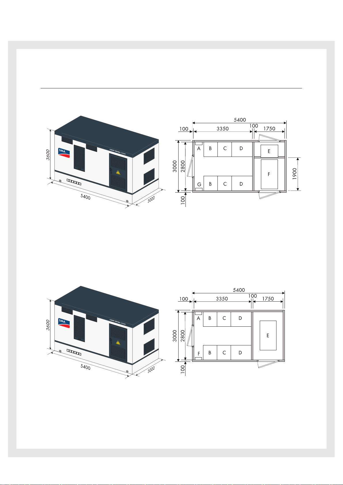
Sunny Central 800MV / 1000MV / 1250MV with medium-voltage switchgear
All figures in mm.
A COM-B, optional B Sunny Central, DC cabinet
C Sunny Central, inverter cabinet D Sunny Central, AC cabinet
E Medium-voltage switchgear F Transformer
G Station sub-distribution
Sunny Central 800MV / 1000MV / 1250MV without medium-voltage switchgear
All figures in mm.
A COM-B, optional B Sunny Central, DC cabinet
C Sunny Central, inverter cabinet D Sunny Central, AC cabinet
E Transformer F Station sub-distribution
SMA Solar Technology AG 2/14
Technical Information Mechanical data
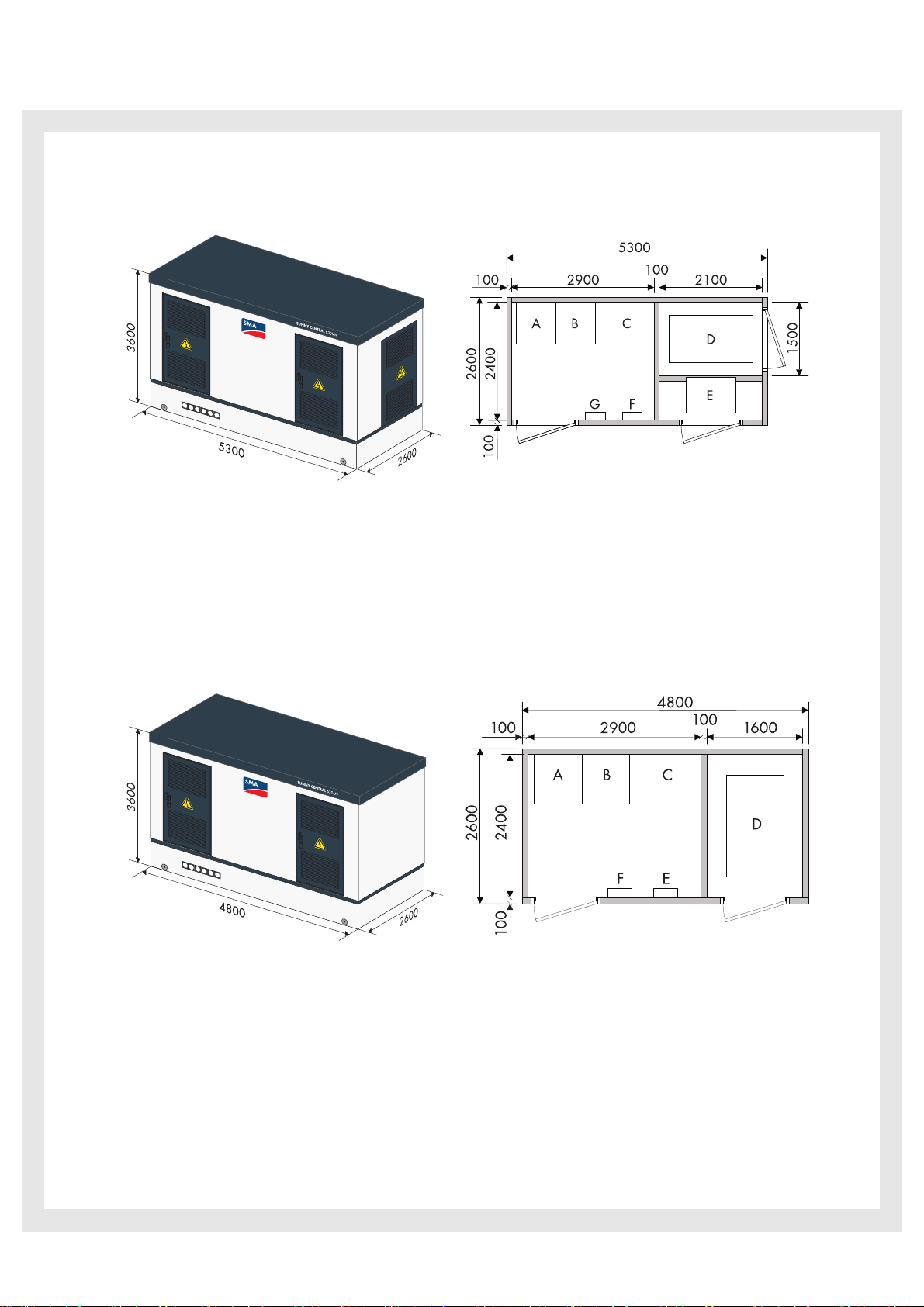
Sunny Central 400MV / 500MV / 630MV with medium-voltage switchgear
All figures in mm.
A Sunny Central, DC cabinet B Sunny Central, inverter cabinet
C Sunny Central, AC cabinet D Transformer
E Medium-voltage switchgear F Station sub-distribution
G COM-B, optional
Sunny Central 400MV / 500MV / 630MV without medium-voltage switchgear
All figures in mm.
A Sunny Central, DC cabinet B Sunny Central, inverter cabinet
C Sunny Central, AC cabinet D Transformer
E Station sub-distribution F COM-B, optional
SMA Solar Technology AG 3/14

Technical Information Transport Requirements
max. 7,000 mmmax. 7,000 mm
7,500 mm
Semi-trailer with MV station
Alternative position for semitrailer with MC station
Crane
2 Transport Requirements
2.1 Freight-forwarding Company
Transport and unloading is coordinated by a freight-forwarding company. Normally, the freight-forwarding
company will arrange a day for delivery and unloading with the site management two weeks prior to the
planned delivery date.
2.2 Ambient Conditions
The transport route within the PV farm must be designed in such a way that the MV station can be transported
by a semi-trailer. The semi-trailer weighs 60 t with a length of 16 m, a width of 3 m, a height of 5 m and a
ground clearance of 0.25 m. At its final destination, the surface must be dry,solid and even.
The concrete station is lifted off the semi-trailer and set down on the foundation by a crane. The pivoting radius
of the crane is 7 m. The semi-trailer must be positioned as indicated in the following graphic.
If the ambient conditions cannot be fulfilled, it may be necessary to use a larger crane. The final crane size is
determined via a visit to the site.
SMA Solar Technology AG 4/14
Technical Information Transport Requirements
Remove all obstacles prior to delivery such as fences, power lines, trees and such which could hinder
access by the semi-trailer and crane.
Delivery and transport using a crane of up to 7 m radius are included in the scope of delivery. Additional
costs can be accrued during delivery if
• traffic-control measures such as road blocks, police escorts, etc. are necessary.
• a crane with radius of over 7 m is required.
• an extra traction engine is required for steep inclines.
• excavator mats, etc. are needed.
2.3 Foundation
The building pit and foundation are to be set up on site in accordance with the foundation plan. The following
conditions must be fulfilled:
• The digging depth may not exceed 0.8 m.
• Exterior grounding installations are to be executed according to the instructions of the utility operator or
distribution grid operator.
• The work area must have a minimum circumference of 0.5 m.
• The corners of the building pit must be marked.
• Place the material dug out in such a way that the semi-trailer and the crane are not hindered during
transport.
• The ground must have the following properties:
‒ Approx. 100 mm high
‒ Compression ratio: 98 %
‒ Soil pressure: 150 kN/m²
‒ Planning levels deducted
SMA Solar Technology AG 5/14
 Loading...